EP3349666B1 - Control mechanism for steerable rod - Google Patents
Control mechanism for steerable rod Download PDFInfo
- Publication number
- EP3349666B1 EP3349666B1 EP16775497.7A EP16775497A EP3349666B1 EP 3349666 B1 EP3349666 B1 EP 3349666B1 EP 16775497 A EP16775497 A EP 16775497A EP 3349666 B1 EP3349666 B1 EP 3349666B1
- Authority
- EP
- European Patent Office
- Prior art keywords
- rod
- sliding
- drive shaft
- control mechanism
- shaft
- Prior art date
- Legal status (The legal status is an assumption and is not a legal conclusion. Google has not performed a legal analysis and makes no representation as to the accuracy of the status listed.)
- Active
Links
- 230000007246 mechanism Effects 0.000 title claims description 43
- 239000000463 material Substances 0.000 claims description 17
- 230000000903 blocking effect Effects 0.000 claims description 5
- 229910000990 Ni alloy Inorganic materials 0.000 claims description 3
- 229910001069 Ti alloy Inorganic materials 0.000 claims description 3
- RTAQQCXQSZGOHL-UHFFFAOYSA-N Titanium Chemical compound [Ti] RTAQQCXQSZGOHL-UHFFFAOYSA-N 0.000 claims description 3
- 238000006073 displacement reaction Methods 0.000 claims description 3
- 239000010936 titanium Substances 0.000 claims description 3
- 210000001519 tissue Anatomy 0.000 description 16
- 210000000988 bone and bone Anatomy 0.000 description 7
- 229910000831 Steel Inorganic materials 0.000 description 5
- 239000010935 stainless steel Substances 0.000 description 5
- 229910001220 stainless steel Inorganic materials 0.000 description 5
- 239000010959 steel Substances 0.000 description 5
- 238000001802 infusion Methods 0.000 description 4
- 238000002347 injection Methods 0.000 description 4
- 239000007924 injection Substances 0.000 description 4
- 230000013011 mating Effects 0.000 description 4
- 239000002639 bone cement Substances 0.000 description 3
- 238000003780 insertion Methods 0.000 description 3
- 230000037431 insertion Effects 0.000 description 3
- 238000013519 translation Methods 0.000 description 3
- 206010010214 Compression fracture Diseases 0.000 description 2
- 229920002614 Polyether block amide Polymers 0.000 description 2
- 239000004568 cement Substances 0.000 description 2
- 238000000034 method Methods 0.000 description 2
- 230000002787 reinforcement Effects 0.000 description 2
- 238000001356 surgical procedure Methods 0.000 description 2
- 208000001132 Osteoporosis Diseases 0.000 description 1
- 206010058907 Spinal deformity Diseases 0.000 description 1
- 208000027418 Wounds and injury Diseases 0.000 description 1
- 238000013459 approach Methods 0.000 description 1
- 230000005465 channeling Effects 0.000 description 1
- 230000006835 compression Effects 0.000 description 1
- 238000007906 compression Methods 0.000 description 1
- 230000006378 damage Effects 0.000 description 1
- 208000014674 injury Diseases 0.000 description 1
- 229910052751 metal Inorganic materials 0.000 description 1
- 239000002184 metal Substances 0.000 description 1
- 206010061289 metastatic neoplasm Diseases 0.000 description 1
- 238000012986 modification Methods 0.000 description 1
- 230000004048 modification Effects 0.000 description 1
- 229910001000 nickel titanium Inorganic materials 0.000 description 1
- HLXZNVUGXRDIFK-UHFFFAOYSA-N nickel titanium Chemical compound [Ti].[Ti].[Ti].[Ti].[Ti].[Ti].[Ti].[Ti].[Ti].[Ti].[Ti].[Ni].[Ni].[Ni].[Ni].[Ni].[Ni].[Ni].[Ni].[Ni].[Ni].[Ni].[Ni].[Ni].[Ni] HLXZNVUGXRDIFK-UHFFFAOYSA-N 0.000 description 1
- 230000000399 orthopedic effect Effects 0.000 description 1
- 230000000452 restraining effect Effects 0.000 description 1
- 229910001285 shape-memory alloy Inorganic materials 0.000 description 1
- 210000004872 soft tissue Anatomy 0.000 description 1
- 239000011800 void material Substances 0.000 description 1
Images






Classifications
-
- A—HUMAN NECESSITIES
- A61—MEDICAL OR VETERINARY SCIENCE; HYGIENE
- A61B—DIAGNOSIS; SURGERY; IDENTIFICATION
- A61B17/00—Surgical instruments, devices or methods
- A61B17/32—Surgical cutting instruments
- A61B17/320016—Endoscopic cutting instruments, e.g. arthroscopes, resectoscopes
-
- A—HUMAN NECESSITIES
- A61—MEDICAL OR VETERINARY SCIENCE; HYGIENE
- A61B—DIAGNOSIS; SURGERY; IDENTIFICATION
- A61B17/00—Surgical instruments, devices or methods
- A61B17/16—Instruments for performing osteoclasis; Drills or chisels for bones; Trepans
- A61B17/1662—Instruments for performing osteoclasis; Drills or chisels for bones; Trepans for particular parts of the body
- A61B17/1671—Instruments for performing osteoclasis; Drills or chisels for bones; Trepans for particular parts of the body for the spine
-
- A—HUMAN NECESSITIES
- A61—MEDICAL OR VETERINARY SCIENCE; HYGIENE
- A61B—DIAGNOSIS; SURGERY; IDENTIFICATION
- A61B17/00—Surgical instruments, devices or methods
- A61B17/16—Instruments for performing osteoclasis; Drills or chisels for bones; Trepans
- A61B17/1642—Instruments for performing osteoclasis; Drills or chisels for bones; Trepans for producing a curved bore
-
- A—HUMAN NECESSITIES
- A61—MEDICAL OR VETERINARY SCIENCE; HYGIENE
- A61B—DIAGNOSIS; SURGERY; IDENTIFICATION
- A61B17/00—Surgical instruments, devices or methods
- A61B17/34—Trocars; Puncturing needles
- A61B17/3472—Trocars; Puncturing needles for bones, e.g. intraosseus injections
-
- A—HUMAN NECESSITIES
- A61—MEDICAL OR VETERINARY SCIENCE; HYGIENE
- A61B—DIAGNOSIS; SURGERY; IDENTIFICATION
- A61B17/00—Surgical instruments, devices or methods
- A61B17/56—Surgical instruments or methods for treatment of bones or joints; Devices specially adapted therefor
- A61B17/58—Surgical instruments or methods for treatment of bones or joints; Devices specially adapted therefor for osteosynthesis, e.g. bone plates, screws or setting implements
- A61B17/88—Osteosynthesis instruments; Methods or means for implanting or extracting internal or external fixation devices
- A61B17/8802—Equipment for handling bone cement or other fluid fillers
- A61B17/8805—Equipment for handling bone cement or other fluid fillers for introducing fluid filler into bone or extracting it
-
- A—HUMAN NECESSITIES
- A61—MEDICAL OR VETERINARY SCIENCE; HYGIENE
- A61B—DIAGNOSIS; SURGERY; IDENTIFICATION
- A61B17/00—Surgical instruments, devices or methods
- A61B17/56—Surgical instruments or methods for treatment of bones or joints; Devices specially adapted therefor
- A61B17/58—Surgical instruments or methods for treatment of bones or joints; Devices specially adapted therefor for osteosynthesis, e.g. bone plates, screws or setting implements
- A61B17/88—Osteosynthesis instruments; Methods or means for implanting or extracting internal or external fixation devices
- A61B17/8802—Equipment for handling bone cement or other fluid fillers
- A61B17/8805—Equipment for handling bone cement or other fluid fillers for introducing fluid filler into bone or extracting it
- A61B17/8811—Equipment for handling bone cement or other fluid fillers for introducing fluid filler into bone or extracting it characterised by the introducer tip, i.e. the part inserted into or onto the bone
-
- A—HUMAN NECESSITIES
- A61—MEDICAL OR VETERINARY SCIENCE; HYGIENE
- A61B—DIAGNOSIS; SURGERY; IDENTIFICATION
- A61B17/00—Surgical instruments, devices or methods
- A61B17/34—Trocars; Puncturing needles
- A61B17/3478—Endoscopic needles, e.g. for infusion
-
- A—HUMAN NECESSITIES
- A61—MEDICAL OR VETERINARY SCIENCE; HYGIENE
- A61B—DIAGNOSIS; SURGERY; IDENTIFICATION
- A61B17/00—Surgical instruments, devices or methods
- A61B17/00234—Surgical instruments, devices or methods for minimally invasive surgery
- A61B2017/00292—Surgical instruments, devices or methods for minimally invasive surgery mounted on or guided by flexible, e.g. catheter-like, means
- A61B2017/003—Steerable
- A61B2017/00318—Steering mechanisms
- A61B2017/00331—Steering mechanisms with preformed bends
-
- A—HUMAN NECESSITIES
- A61—MEDICAL OR VETERINARY SCIENCE; HYGIENE
- A61B—DIAGNOSIS; SURGERY; IDENTIFICATION
- A61B17/00—Surgical instruments, devices or methods
- A61B2017/00831—Material properties
- A61B2017/0084—Material properties low friction
- A61B2017/00845—Material properties low friction of moving parts with respect to each other
-
- A—HUMAN NECESSITIES
- A61—MEDICAL OR VETERINARY SCIENCE; HYGIENE
- A61B—DIAGNOSIS; SURGERY; IDENTIFICATION
- A61B17/00—Surgical instruments, devices or methods
- A61B2017/00831—Material properties
- A61B2017/00867—Material properties shape memory effect
-
- A—HUMAN NECESSITIES
- A61—MEDICAL OR VETERINARY SCIENCE; HYGIENE
- A61B—DIAGNOSIS; SURGERY; IDENTIFICATION
- A61B17/00—Surgical instruments, devices or methods
- A61B2017/00982—General structural features
- A61B2017/00991—Telescopic means
-
- A—HUMAN NECESSITIES
- A61—MEDICAL OR VETERINARY SCIENCE; HYGIENE
- A61B—DIAGNOSIS; SURGERY; IDENTIFICATION
- A61B17/00—Surgical instruments, devices or methods
- A61B17/32—Surgical cutting instruments
- A61B2017/320056—Tunnelers
Definitions
- the present invention pertains to the field of medical devices, in particular orthopedic devices.
- the invention especially relates to improved mechanisms for controlling a rod used for creating cavities in tissue.
- Vertebral compression fractures involve the collapse of one or more vertebral bodies in the spine.
- Vertebral compression fractures or related spinal deformities may initiate, for instance, from metastatic diseases, injuries or osteoporosis.
- vertebroplasty Conventional surgery for treating vertebral compression, often referred to as vertebroplasty, includes a cannula or a needle inserted through the posterior of a targeted vertebral body, usually through the pedicles. Once positioned within the compressed vertebral body, bone cement is pushed through the needle into the vertebral body. Variations of vertebroplasty include the deployment of mechanical devices or expansion of a balloon to restore the height of the vertebral body and to create a void in a compressed vertebral body; bone cement is then inserted into the space to stabilize the devices and to strengthen the vertebral body.
- curved needles are often made of shape-memory alloys.
- WO 00/33909 discloses a needle assembly comprising a hollow, curved, superelastic infusion needle.
- the needle assembly comprises an infusion needle made of a superelastic material such as nitinol and an outer cannula for introduction into the body of a patient.
- the said rigid outer cannula is required as the initial access to the vertebral body must be made using a relatively straight approach.
- the needle cannula Upon deployment from the outer cannula, the needle cannula substantially returns to the preformed curved configuration for the introduction of materials at areas lateral to the entry path of the needle assembly.
- a trocar is inserted inside the outer cannula during introduction; once the outer cannula has been directed to the target site, the trocar is removed and the infusion needle is inserted into the said outer cannula.
- WO2014/093464 discloses a friction reduction covering sized to be received in a cannula and a cavity creation member, biased from a retracted to a deployed configuration, sized to be disposed in the friction reduction covering. With such devices, the curved needle is enclosed within a rigid covering. Consequently, there is reduced friction between the curved needle and the cannula during the surgical procedure. However, within WO2014/093464 the friction reduction covering is not secured to the handle and slides freely in at least one direction.
- US 2010/324506 and US2013/245533 disclose respectively a system for channeling a path into bone and a device for establishing a transjugular intrahepatic portosystemic shunt. Therefore there is still of need for improved control of the deployment of the curved needle relative to the handle and/or the friction reduction covering.
- the present invention relates to a mechanism for controlling rods used for creating cavities in tissue.
- the control mechanism may further be used for injecting material within said cavity.
- the present invention also relates to steerable devices for creating cavities and injecting material in tissue, the said devices comprising the control mechanism of the invention and the rod.
- the present invention thus relates to a control mechanism for controlling a rod having a preformed bent and at least one key, the control mechanism comprising:
- the sliding ring comprises a threaded inner surface and the sliding shaft comprises at least one protrusion protruding outwardly from the sliding shaft and engaging the at least one threaded inner surface of the sliding ring so that axial rotation of the sliding ring causes the sliding shaft to move back and forth along the longitudinal axis.
- the blocking means comprise at least one key or at least one longitudinal keyseat within the external surface of the drive shaft engaged in respectively at least one longitudinal keyseat or at least one key within the internal surface of the sliding shaft.
- the connecting means between the drive shaft and the sliding ring comprise a bearing such as a plain bearing.
- the friction reduction cannula has a longitudinal axis and comprises an opening configured to receive and restrain at least partially the rod, especially the preformed bent, in a straight configuration along the longitudinal axis.
- the friction reduction cannula is made from steel, preferably stainless steel.
- the friction reduction cannula comprises a proximal part and a distal part, wherein the distal part is more flexible than the proximal part so that the proximal part restrains the rod in the straight configuration and the distal part does not restrain the rod in the straight configuration.
- the proximal part of the friction reduction cannula is made from steel, such as stainless steel and a distal part is made from a polymeric material such as polyether block amide.
- the drive shaft further comprises at its proximal end a connecting thread.
- control mechanism further comprising a connecting cap comprising a threaded inner surface assembled onto the connecting thread, the said connecting cap comprising a plurality of flexible lugs, protruding distally and outwardly, designed to engage a plurality of openings at or near the proximal end of the sliding ring thereby preventing rotation of the sliding ring.
- the connecting cap further comprises at least one protrusion or recess, preferably a sawtooth protrusion or a sawtooth recess.
- the sliding shaft further comprises a hub protruding distally and outwardly.
- the hub comprises a locking ring designed to secure the sliding shaft with a trocar.
- the present invention also relates to a steerable device comprising a control mechanism according to the invention and a rod having a preformed bent and at least one key, the rod being preferably made from a superelastic material, such as an alloy of nickel and titanium.
- the angle of deflection of the rod ranges from 20° to 150°, preferably from 30° to 130°, more preferably from 40° to 110°.
- the rod comprises at its proximal end a knob comprising a threaded inner surface designed to be assembled onto the connecting cap, the knob and the rod being connected by means of a bearing which allow axial rotation between the knob and the rod.
- the knob further comprises at least one protrusion or recess, preferably a sawtooth protrusion or a sawtooth recess designed to be engaged with respectively at least one recess or protrusion of the connecting cap thereby preventing rotation between the connecting cap and the knob.
- the present invention also relates to a steerable system comprising a steerable device according to the present invention and a trocar, preferably a bone access trocar, suitable to be positioned adjacent to an exterior surface of a targeted tissue.
- a steerable system comprising a steerable device according to the present invention and a trocar, preferably a bone access trocar, suitable to be positioned adjacent to an exterior surface of a targeted tissue.
- the steerable device especially the friction reduction cannula, is inserted in the trocar and connected by the locking ring.
- the trocar is threadedly connected to the hub.
- control mechanism comprises a friction reduction cannula made from steel, preferably stainless steel.
- a control mechanism for controlling a rod used for creating cavities in tissue comprising a friction reduction cannula and a handle.
- control mechanism 100 elongates along a longitudinal axis 101 between a proximal end 100a and a distal end 100b spaced apart from the proximal end 100a.
- the control mechanism 100 comprises a friction reduction cannula 110 and a handle 130.
- the handle 130 is configured to be grasped by the user and comprises a sliding ring 131, a sliding shaft 132 and a drive shaft 133.
- the handle 130 extends along a longitudinal axis 101 from a proximal end to a distal end.
- the sliding ring 131 is cylindrical or tubular, extends along a longitudinal axis 101 and comprises a central opening from a proximal end 131a to a distal end 131b. According to one embodiment, the central opening is configured to receive the sliding shaft 132 and the drive shaft 133. According to one embodiment, the sliding ring 131, especially the central opening comprises a threaded inner surface. According to one embodiment, the threaded inner surface of the sliding ring 131 is a cylindrical surface formed with a continuous thread.
- the sliding shaft 132 is cylindrical or tubular, extends along a longitudinal axis 101 and comprises a central opening from a proximal end 132a to a distal end 132b. According to one embodiment, the central opening is configured to receive a drive shaft 133. According to one embodiment, the sliding ring 131 is cylindrical and is outside and encloses at least partially the sliding shaft 132. According to one embodiment, the sliding shaft 132 comprises at least one tab, pin or protrusion 1321 extending outwardly, preferably at the proximal end thereof 132a. According to one embodiment, the outer surface of the sliding shaft 132 comprises marks indicating the translation of the sliding ring 131 relative to the sliding shaft 132.
- the sliding ring 131 is threadedly connected to the sliding shaft 132.
- the protrusion(s) 1321 of the sliding shaft 132 engage or mate with threaded inner surface of the sliding ring 131.
- the external protrusion(s) 1321 of the sliding shaft 132 is engaged with the internal thread of threaded inner surface of the sliding ring 131.
- Rotation of the sliding ring 131 causes sliding shaft 132 to move relatively along a helical path of the thread of threaded inner surface of the sliding ring 131.
- rotation of the sliding ring 131 causes protrusions 1321 of the sliding shaft 132 to track the helical path of the thread of threaded inner surface of the sliding ring 131.
- rotation about the longitudinal axis of the sliding ring 131 causes the sliding shaft 132 to move back and forth along the longitudinal axis 101, relative to the sliding ring 131.
- rotation of the sliding ring 131 causes the sliding ring 131 to move back and forth along the longitudinal axis 101 in rotation.
- the sliding ring is threadedly connected to the sliding shaft;
- the sliding shaft 132 comprises a threaded outer surface and the sliding ring comprises an at least one tab, pin or protrusion extending inwardly, preferably at the distal end thereof and engage the threaded outer surface of the sliding shaft.
- the drive shaft 133 is cylindrical or tubular, extends along a longitudinal axis 101 and comprises a central opening from a proximal end 133a to a distal end 133b.
- the sliding shaft 132 is cylindrical and is outside and encloses at least partially the drive shaft 133.
- the drive shaft 133 is configured to slide longitudinally inside the sliding shaft 132.
- the drive shaft 133 and the sliding shaft 132 are connected by blocking means which prevent axial rotation between the drive shaft 133 and the sliding shaft 132 and which allow the drive shaft 133 to slide within the sliding shaft 132.
- the drive shaft 133 comprises at least one key sliding in a keyseat, such as at least one longitudinal slot, in the internal surface of the sliding shaft 132.
- the sliding shaft 132 comprises at least one key sliding in a keyseat, such as at least one longitudinal slot, in the external surface of the drive shaft 133. Consequently, the drive shaft 133 is prevented from rotating axially relative to said sliding shaft 132.
- the drive shaft 133 is connected to the sliding ring 131 by means of a connecting means, such as shoulders and grooves.
- the said connecting means form a bearing, such as a plain bearing.
- the bearing allows axial rotation of the sliding ring 131 relative to the drive shaft 133 about the longitudinal axis of the rod.
- the bearing prevents any other degrees of freedom.
- the drive shaft 133 is connected with the sliding ring 131 by means of a bearing which prevents axial displacement between the drive shaft 132 and the sliding ring 131 and which allows axial rotation between the drive shaft 132 and the sliding ring 131.
- the drive shaft 133 translates in a longitudinal axis relative to the sliding shaft 132.
- the drive shaft 133 and the siding ring 131 are connected together at or near their proximal end 131a, 133a.
- the proximal end 133a of the drive shaft 133 comprises a connecting thread 1331, protruding proximally.
- the said connecting thread 1331 is any connecting thread known by one skilled in the art such as a "luer" type allowing connections of multiple devices equipped with mating threads.
- the handle 130 comprises a connecting cap 135 comprising an inner thread so that the connecting cap 135 can be assembled onto the connecting thread 1331.
- the connecting cap 135 comprises a plurality of flexible lugs 1351 protruding outwardly and distally. Said flexible lugs 1351 engage a plurality of openings at or near the proximal end 131a of the sliding ring 131 thereby preventing rotation of the sliding ring. Consequently when the connecting cap 135 is assembled onto the connecting thread 1331, the sliding ring 131 cannot axially rotate about the longitudinal axis 101 relative to the sliding shaft 132.
- the outer surface of the connecting cap 135 comprises a thread.
- the sliding shaft 132 comprises a hub 1322 extending distally and outwardly from the sliding shaft 132.
- the connection between the hub 1322 and the sliding shaft 132 prevents any degrees of freedom.
- the sliding shaft 132 and the hub 1322 are integral.
- the handle 130, especially the sliding shaft 132, more particularly the hub 1322 comprises arrows pointing to the same direction.
- the handle 130 may be manipulated from a retracted position to a deployed position.
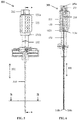
- the protrusion(s) 1321 of the sliding shaft 132 engage the distal end of the thread of the sliding ring 131, as depicted in figures 5, 6 and 9 .
- the protrusion 1321 of the sliding shaft 132 engage the proximal end of the thread of the sliding ring 131 as depicted in figures 7,8 and 9 .
- the friction reduction cannula 110 extends along a longitudinal axis 101.
- the friction reduction cannula defines a proximal end 110a and a distal end 110b that is spaced apart from the proximal end 110a along the longitudinal axis.
- the friction reduction cannula 110 also defines an outer cannula surface and an inner cannula surface opposite the outer cannula surface.
- the inner cannula surface defines a cannula opening elongating along the longitudinal axis between the proximal end 110a and the distal end 110b.
- the cross-sectional section of the inner cannula surface of the friction reduction cannula 110 is constant along the longitudinal axis.
- the friction reduction cannula opening is configured and sized to receive at least a portion of a rod 210.
- the friction reduction cannula 110 is configured to enclose at least partially a rod 210 as depicted in figure 10 , 11 and 12 .
- the friction reduction cannula 110 when used with a rod 210, is configured to restrain at least partially the rod 210 in a straight configuration along the longitudinal axis in order to ease insertion of the rod within a trocar 310, such as a bone access trocar. According to one embodiment, the friction reduction cannula 110 is configured to be used coaxially with the rod 210 for restraining at least partially the rod 210 is a straight configuration along the longitudinal axis.
- the cross-sectional section of the outer cannula surface of the friction reduction cannula 110 is constant along the longitudinal axis.
- the friction reduction cannula opening is configured and sized to be received in at least a portion of a trocar 310, such as a bone access trocar.
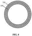
- the trocar 310 is configured to enclose at least partially the friction reduction cannula 110 as depicted in figure 4 .
- the handle 130 further comprises locking means configured to connect a trocar 310, sized to enclose at least partially the friction reduction cannula 110, to the handle 130.
- said locking means may be positioned on the hub 1322 and may be a locking ring 1323 or any connecting thread.
- the friction reduction cannula 110 is secured to drive shaft 133.
- the proximal end of the friction reduction canula 110a is secured to distal end 133b of the drive shaft 133.
- the drive shaft 133 is molded over the friction reduction cannula 110.
- the friction reduction cannula 110 and the drive shaft 133 are connected by an O-ring.
- the friction reduction cannula 110 is secured to the sliding shaft 132, especially with the hub 1322.
- the proximal end of the friction reduction canula 110a is secured to the distal end of the sliding shaft 132b, especially with the hub 1322.
- the friction reduction cannula 110 comprises a proximal part 111 and a distal part 112.
- the distal part of the friction reduction cannula 112 is more flexible than the proximal part of the friction reduction cannula 111.
- the proximal part of the friction reduction cannula 111 is made from steel, preferably stainless steel.
- the distal part of the friction reduction cannula 112 is made from polymeric material, such as polyether block amide.
- the ratio between the length along the longitudinal axis of the distal part 112 and the length along the longitudinal axis of the proximal part 111 is ranging from 1/2 to 1/6.
- the distal part of the friction reduction cannula 112 when used with a rod having a predefined bent, has a length equal to the length of the bent part of the rod 210.
- the proximal part of the friction reduction cannula 111 when used with a rod 210 having a predefined bent, is configured to restrain the rod 210 in a straight configuration when the distal end 210b of the rod does not extend out distally from the proximal part 111.
- the distal part of the friction reduction cannula 112 is not configured to restrain the rod 210 in a straight configuration when the distal end 210b of the rod 210 extends out distally from the proximal part 111 ; the distal part 112 follows the curvature of the rod 210.
- the friction reduction cannula 110 when the friction reduction cannula 110 is secured to the drive shaft 133, the friction reduction cannula is made of two parts: a proximal part 111 and a distal part 112 more flexible then the proximal part.
- the distal part 112 in order to avoid that the distal part 112 shrinks during insertion in the tissue, the distal part comprises metal reinforcements.
- the polymeric material of the distal part 112 is over-molded on the metallic reinforcements.
- the friction reduction cannula 110 is made in a single piece.
- the friction reduction cannula 111 is made from steel, preferably stainless steel.
- the friction reduction cannula 110 when used with a rod 210, is configured to restrain the rod 210 in a straight configuration when the distal end of the rod 210b does not extend out distally from the friction reduction cannula 110.
- the friction reduction cannula 110 when the friction reduction cannula 110 is secured with the sliding shaft 132, the friction reduction cannula 110 is made in a single piece.
- a steerable device for creating cavities and injecting material in tissue using minimally invasive techniques.
- the steerable device 200 comprises the control mechanism 100 of the invention and a rod 210.
- the rod 210 passes through the drive shaft 133 and the sliding shaft 132 of the control mechanism 100.
- the rod 210 has a predefined bend. According to one embodiment, only the distal part of the rod is bent, preferably from 1 to 50%, preferably from 2 to 25%, more preferably from 5 to 10% of the length of the rod 210. According to said embodiment, the proximal part of the rod 210 extends along a longitudinal axis 101.
- the rod 210 defines a proximal end 210a and a distal end 210b that is spaced apart from the proximal end 210a
- the angle of deflection of the rod 210 ranges from 20° to 150°, preferably from 30° to 130°, more preferably from 40° to 110° (as measured from the longitudinal axis).
- the cross-sectional section of the rod 210 is constant. According to one embodiment, the rod 210 has no opening along its length.
- the length of the rod 210 along the longitudinal axis 110 is equal to the length along the longitudinal axis 110 from the proximal end of the handle 130 to the distal end of the friction reduction cannula 110b.
- the rod 210 comprises a superelastic material, preferably an alloy of nickel and titanium.
- the rod 210 comprises a knob 211 at its proximal end 210a.
- the knob 211 is free in rotation relative to the rod 210.
- the rod 210 is connected to the knob 211 by means of a bearing, such as a plain bearing.
- the bearing allows axial rotation of the knob 211 relative to the rod 210 about the longitudinal axis of the rod.
- the knob 211 comprises a threaded inner surface suitable for mating the thread of the connecting cap 135.
- the knob 211 of the rod 210 may be screw on the connecting cap 135 without axial rotation of the rod 210.
- the knob 211 further comprises at the distal end of the threaded inner surface a protrusion, such as a sawtooth protrusion, or a recess to be engaged in respectively a recess or a protrusion 1352 within the connecting cap 135.
- a protrusion such as a sawtooth protrusion
- a recess to be engaged in respectively a recess or a protrusion 1352 within the connecting cap 135.
- the threaded inner surface of the knob 211 depresses the flexible lugs 1351 inside the central opening of the sliding ring, so that the sliding ring 131 may be rotated relative to the drive shaft 133. Consequently, when the knob 211 of the rod 210 has been screwed onto the connecting cap 135, the sliding ring 131 can axially rotate about the longitudinal axis 101 relative to the sliding shaft 132.
- the deflection plane of the rod 210 may be pre-determined.
- the rod 210 comprises, preferably proximally, at least one key sliding in a keyseat, such as at least one longitudinal slot, in the internal surface of the drive shaft 133. Consequently, the rod 210 is prevented from rotating axially relative to said drive shaft 133. Due to the said key of the rod 210, the deflection plane of the rod 210 may be predefined relative to the drive shaft 133.
- the deflection plane of the rod 210 is also predefined relative to the sliding shaft 132 and thus relative to the hub 1322 of the handle; so that the arrows of the hub 1322 point towards the direction of the preformed bent of the rod 210.
- a steerable system 300 for creating cavities and injecting material in tissue using minimally invasive techniques.
- the steerable system 300 comprises the steerable device of the invention and a trocar 310, such as a bone access trocar.
- the trocar 310 extends along a longitudinal axis 101 from a proximal end 310a to a distal end 310b spaced apart from the proximal end 310a along the longitudinal axis 101.
- the length of the trocar 310 along the longitudinal axis 101 is equal to the length along the longitudinal axis 101 of the friction reduction cannula 130 from the hub 1322 to the distal end of the friction reduction cannula 110b.
- the trocar 310 also defines an outer trocar surface and an inner trocar surface opposite the outer trocar surface.
- the inner trocar surface defines a trocar opening elongating along the longitudinal axis 101 between the distal end 310b and the proximal end 310a.
- the trocar opening is configured and sized to receive at least a portion of the steerable device according to the invention, especially at least a portion of the friction reduction cannula 110.
- the cross-sectional section of the inner surface of the trocar 310 is constant along the longitudinal axis 101.
- the trocar 310 is connected to the distal end of the handle 130, preferably to the distal end of the sliding shaft 132b, more preferably to the hub 1322.
- the control mechanism 100 especially the friction reduction cannula 110, is inserted in the trocar 310 and the trocar 310 is connected to the distal end of the handle 130, preferably to the distal end of the sliding shaft 132b, more preferably to the hub 1322, by a locking ring 1323.
- the trocar 310 comprises a connecting thread 311 at its proximal end 310a.
- the said connecting thread 311 is any connecting thread known by one skilled in the art such as a "luer" type allowing connections of multiple devices equipped with mating threads
- the trocar 310 is threadedly connected to the distal end of the handle 130, preferably to the distal end of the sliding shaft 132b, more preferably to the hub 1322, in a detachable manner.
- the hub 1322 comprises a locking ring 1323 for locking the trocar 310 onto the handle 130.
- the mating surfaces between the sliding shaft 132 and the trocar 310 guarantee that the control mechanism 100 is properly located onto the trocar 310 both in longitudinal translation and in axial rotation about the longitudinal axis.
- the locking ring 1323 when the locking ring 1323 is actuated, there is no degree of freedom between the handle 130 and the trocar 310 ; the trocar 130 is secured to the hub 1322.
- the friction reduction cannula 110 when the friction reduction cannula 110 is made in a single piece, the friction reduction cannula 110 is secured to the siding shaft 132.
- the rod 210 is inserted within the control mechanism 100 with the handle 130 is in the retracted position.
- the knob 211 of the rod 210 is screwed onto the connecting cap 135.
- the rod 210 is in a straight configuration.
- the control mechanism 100 comprising the rod 210 in its retracted position may then be slid through the trocar 310 which has been placed in an appropriate location in the patient's tissue.
- the rod may then be deployed by rotating the sliding ring in the deployed configuration. In the deployed configuration, the rod 210 extends laterally outside of the friction reduction cannula 110 and of the trocar 310. Said steps may be repeated with different direction of the deflection plane, in order to create multiple interdigitated cavities.
- the rod 210 may be removed by unscrewing the knob 211 and thus allowing access to the connecting thread 1331 (the connecting cap 135 being removed with the knob 211 ).
- An injection device 320 may then be connected to the connecting thread 1331 in order to inject material within the created cavities through the drive shaft 133 and the friction reduction cannula 110.
- the friction reduction cannula 110 when the friction reduction cannula 110 is made in a two parts, the friction reduction cannula 110 is secured with the drive shaft 133.
- the steerable device 110 needs to be armed in order to bring the distal end of the rod 210b from a retracted position inside the proximal part of the friction reduction cannula 111, as depicted in figure 10 , to an operational position at the distal end of the distal part of the friction reduction cannula 112, as depicted in figures 5 and 6 .
- the rod 210 is pushed until the knob 211 comes in contact with the connecting cap 135.
- the knob 211 is then screwed on the connecting cap 135.
- protrusion or recess of the knob 211 engages respectively a recess or protrusion 1352 of the connecting cap 135, thus locking the knob 211 on the connecting cap 135.
- Screwing fully knob 211 onto the connecting cap 135 also pushes inwards the flexible lugs 1351, freeing them from the corresponding openings in the proximal end of the sliding ring 131a, thus allowing rotation of the sliding ring 131.
- the translation of the drive shaft to the deployed position caused by the rotation of the sliding ring 131 drives both the friction reduction cannula 110 and the rod 210 to extends out of the trocar laterally, thus creating a cured cavity in the tissue, as depicted in figures 7 and 8 .
- the rod 210 may be removed by unscrewing the knob 211 and thus allowing access to the connecting thread 1331 (the connecting cap 135 being removed with the knob 211 ).
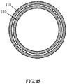
- An injection device may then be connected to the connecting thread 1331 in order to inject material within the created cavities through the drive shaft 133 and the friction reduction cannula 110, as depicted in figures 13, 14 and 15 . Due to the flexible part of the friction reduction cannula 112 and by rotating the handle from the deployed position to the retracted position, material may be injected in a retrograde manner.
- the material may be any material known to one skilled in the art, such as bone cement.
- figures 1 to 15 relate to a control mechanism, a steerable device and a steerable system wherein the friction reduction cannula comprises a distal part and a proximal part and is connected to the drive shaft.
- Figures 16 to 18 relate to a control mechanism, a steerable device and a steerable system wherein the friction reduction cannula is made of a single piece and is connected to the sliding shaft.
Landscapes
- Health & Medical Sciences (AREA)
- Life Sciences & Earth Sciences (AREA)
- Surgery (AREA)
- Orthopedic Medicine & Surgery (AREA)
- Animal Behavior & Ethology (AREA)
- General Health & Medical Sciences (AREA)
- Biomedical Technology (AREA)
- Heart & Thoracic Surgery (AREA)
- Veterinary Medicine (AREA)
- Engineering & Computer Science (AREA)
- Public Health (AREA)
- Molecular Biology (AREA)
- Nuclear Medicine, Radiotherapy & Molecular Imaging (AREA)
- Medical Informatics (AREA)
- Dentistry (AREA)
- Oral & Maxillofacial Surgery (AREA)
- Pathology (AREA)
- Surgical Instruments (AREA)
- Biophysics (AREA)
- Pulmonology (AREA)
- Anesthesiology (AREA)
- Hematology (AREA)
Applications Claiming Priority (2)
| Application Number | Priority Date | Filing Date | Title |
|---|---|---|---|
| FR1558697A FR3040869B1 (fr) | 2015-09-16 | 2015-09-16 | Mecanisme de controle de tige orientable |
| PCT/EP2016/071922 WO2017046298A1 (en) | 2015-09-16 | 2016-09-16 | Control mechanism for steerable rod |
Publications (2)
| Publication Number | Publication Date |
|---|---|
| EP3349666A1 EP3349666A1 (en) | 2018-07-25 |
| EP3349666B1 true EP3349666B1 (en) | 2019-11-27 |
Family
ID=55178097
Family Applications (1)
| Application Number | Title | Priority Date | Filing Date |
|---|---|---|---|
| EP16775497.7A Active EP3349666B1 (en) | 2015-09-16 | 2016-09-16 | Control mechanism for steerable rod |
Country Status (8)
| Country | Link |
|---|---|
| US (2) | US10660659B2 (enExample) |
| EP (1) | EP3349666B1 (enExample) |
| JP (1) | JP6818016B2 (enExample) |
| AU (1) | AU2016325016B2 (enExample) |
| CA (1) | CA2998697C (enExample) |
| ES (1) | ES2764158T3 (enExample) |
| FR (1) | FR3040869B1 (enExample) |
| WO (1) | WO2017046298A1 (enExample) |
Families Citing this family (8)
| Publication number | Priority date | Publication date | Assignee | Title |
|---|---|---|---|---|
| US10390877B2 (en) | 2011-12-30 | 2019-08-27 | Relievant Medsystems, Inc. | Systems and methods for treating back pain |
| IL238516B (en) | 2012-11-05 | 2022-08-01 | Relievant Medsystems Inc | System and methods for creating curved pathways through bone and regulating the nerves within the bone |
| FR3040869B1 (fr) * | 2015-09-16 | 2017-10-20 | Vexim | Mecanisme de controle de tige orientable |
| AU2020346827B2 (en) | 2019-09-12 | 2026-03-12 | Relievant Medsystems, Inc. | Systems and methods for tissue modulation |
| AU2021306313B2 (en) | 2020-07-10 | 2026-07-09 | Relievant Medsystems, Inc. | Vertebral denervation in conjunction with vertebral fusion |
| US12082876B1 (en) | 2020-09-28 | 2024-09-10 | Relievant Medsystems, Inc. | Introducer drill |
| AU2021409967A1 (en) | 2020-12-22 | 2023-08-03 | Relievant Medsystems, Inc. | Prediction of candidates for spinal neuromodulation |
| US12433668B1 (en) | 2021-11-08 | 2025-10-07 | Relievant Medsystems, Inc. | Impedance stoppage mitigation during radiofrequency tissue ablation procedures |
Family Cites Families (24)
| Publication number | Priority date | Publication date | Assignee | Title |
|---|---|---|---|---|
| KR20010040761A (ko) | 1998-12-09 | 2001-05-15 | 쿡 인코포레이티드 | 중공의 만곡형 초탄성 의료용 니들 |
| US8613744B2 (en) * | 2002-09-30 | 2013-12-24 | Relievant Medsystems, Inc. | Systems and methods for navigating an instrument through bone |
| US8808284B2 (en) * | 2008-09-26 | 2014-08-19 | Relievant Medsystems, Inc. | Systems for navigating an instrument through bone |
| US7553307B2 (en) * | 2004-10-15 | 2009-06-30 | Baxano, Inc. | Devices and methods for tissue modification |
| US7648519B2 (en) * | 2006-09-13 | 2010-01-19 | Cambridge Endoscopic Devices, Inc. | Surgical instrument |
| US9480485B2 (en) * | 2006-12-15 | 2016-11-01 | Globus Medical, Inc. | Devices and methods for vertebrostenting |
| US8257386B2 (en) * | 2007-09-11 | 2012-09-04 | Cambridge Endoscopic Devices, Inc. | Surgical instrument |
| US20090171147A1 (en) * | 2007-12-31 | 2009-07-02 | Woojin Lee | Surgical instrument |
| WO2009155319A1 (en) * | 2008-06-17 | 2009-12-23 | Soteira, Inc. | Devices and methods for fracture reduction |
| US10028753B2 (en) * | 2008-09-26 | 2018-07-24 | Relievant Medsystems, Inc. | Spine treatment kits |
| CA2737374C (en) * | 2008-09-26 | 2017-03-28 | Relievant Medsystems, Inc. | Systems and methods for navigating an instrument through bone |
| US8628491B2 (en) * | 2008-12-24 | 2014-01-14 | Sidney Lowell Kahn | Transjugular intrahepatic portosystemic shunt device |
| JP5619875B2 (ja) * | 2009-05-08 | 2014-11-05 | ジンテス ゲゼルシャフト ミット ベシュレンクテル ハフツング | 拡張型骨インプラント |
| US8348950B2 (en) * | 2010-01-04 | 2013-01-08 | Zyga Technology, Inc. | Sacroiliac fusion system |
| US9204891B2 (en) * | 2010-07-07 | 2015-12-08 | Carevature Medical Ltd. | Flexible surgical device for tissue removal |
| EP2704647B1 (en) * | 2011-05-05 | 2016-08-24 | Zyga Technology, Inc. | Sacroiliac fusion system |
| US20130012951A1 (en) * | 2011-07-08 | 2013-01-10 | Carefusion 207, Inc. | Systems and methods for treating a spine through a single vertebral body insertion point |
| IL238516B (en) * | 2012-11-05 | 2022-08-01 | Relievant Medsystems Inc | System and methods for creating curved pathways through bone and regulating the nerves within the bone |
| US9241729B2 (en) * | 2012-12-14 | 2016-01-26 | DePuy Synthes Products, Inc. | Device to aid in the deployment of a shape memory instrument |
| US10085783B2 (en) * | 2013-03-14 | 2018-10-02 | Izi Medical Products, Llc | Devices and methods for treating bone tissue |
| US9351739B2 (en) * | 2013-12-31 | 2016-05-31 | Amendia, Inc. | Tunneling device |
| US9662123B2 (en) * | 2014-07-31 | 2017-05-30 | Amendia, Inc. | Vertical cutter and method of use |
| FR3040869B1 (fr) * | 2015-09-16 | 2017-10-20 | Vexim | Mecanisme de controle de tige orientable |
| CN109862834B (zh) * | 2016-10-27 | 2022-05-24 | Dfine有限公司 | 具有接合剂递送通道的可弯曲的骨凿 |
-
2015
- 2015-09-16 FR FR1558697A patent/FR3040869B1/fr not_active Expired - Fee Related
-
2016
- 2016-09-16 WO PCT/EP2016/071922 patent/WO2017046298A1/en not_active Ceased
- 2016-09-16 EP EP16775497.7A patent/EP3349666B1/en active Active
- 2016-09-16 US US15/760,455 patent/US10660659B2/en active Active
- 2016-09-16 CA CA2998697A patent/CA2998697C/en active Active
- 2016-09-16 ES ES16775497T patent/ES2764158T3/es active Active
- 2016-09-16 JP JP2018513774A patent/JP6818016B2/ja active Active
- 2016-09-16 AU AU2016325016A patent/AU2016325016B2/en not_active Ceased
-
2020
- 2020-05-26 US US16/882,902 patent/US11389181B2/en active Active
Non-Patent Citations (1)
| Title |
|---|
| None * |
Also Published As
| Publication number | Publication date |
|---|---|
| EP3349666A1 (en) | 2018-07-25 |
| FR3040869A1 (enExample) | 2017-03-17 |
| ES2764158T3 (es) | 2020-06-02 |
| AU2016325016A1 (en) | 2018-04-26 |
| CA2998697C (en) | 2020-07-21 |
| US11389181B2 (en) | 2022-07-19 |
| CA2998697A1 (en) | 2017-03-23 |
| US20200281609A1 (en) | 2020-09-10 |
| WO2017046298A1 (en) | 2017-03-23 |
| US20180263648A1 (en) | 2018-09-20 |
| JP2018531661A (ja) | 2018-11-01 |
| FR3040869B1 (fr) | 2017-10-20 |
| AU2016325016B2 (en) | 2021-05-13 |
| US10660659B2 (en) | 2020-05-26 |
| JP6818016B2 (ja) | 2021-01-20 |
Similar Documents
| Publication | Publication Date | Title |
|---|---|---|
| US11389181B2 (en) | Steerable systems and methods for accessing bone | |
| US11090064B2 (en) | Devices and methods for vertebrostenting | |
| EP3958752B1 (en) | Systems for off-axis augmentation of a vertebral body | |
| US11786279B2 (en) | Modular spinal fixation device | |
| JP5931924B2 (ja) | 増強可能な転子大腿骨釘 | |
| US8480675B2 (en) | Betts osteotome | |
| EP2120734B1 (en) | Drills for vertebrostenting | |
| EP2762099B1 (en) | Steerable cannula assembly | |
| US20080221608A1 (en) | Expandable blade device for stabilizing compression fractures | |
| WO2009143496A1 (en) | Devices and methods for spinal reduction, displacement and resection | |
| US20140276471A1 (en) | Devices and methods for treating bone tissue | |
| US20130226187A1 (en) | Devices and methods for injecting fluid into the body | |
| EP3415107B1 (en) | Bone anchor | |
| EP4034011B1 (en) | Flexible spinal fusion rod |
Legal Events
| Date | Code | Title | Description |
|---|---|---|---|
| STAA | Information on the status of an ep patent application or granted ep patent |
Free format text: STATUS: THE INTERNATIONAL PUBLICATION HAS BEEN MADE |
|
| PUAI | Public reference made under article 153(3) epc to a published international application that has entered the european phase |
Free format text: ORIGINAL CODE: 0009012 |
|
| STAA | Information on the status of an ep patent application or granted ep patent |
Free format text: STATUS: REQUEST FOR EXAMINATION WAS MADE |
|
| 17P | Request for examination filed |
Effective date: 20180409 |
|
| AK | Designated contracting states |
Kind code of ref document: A1 Designated state(s): AL AT BE BG CH CY CZ DE DK EE ES FI FR GB GR HR HU IE IS IT LI LT LU LV MC MK MT NL NO PL PT RO RS SE SI SK SM TR |
|
| AX | Request for extension of the european patent |
Extension state: BA ME |
|
| DAV | Request for validation of the european patent (deleted) | ||
| DAX | Request for extension of the european patent (deleted) | ||
| GRAP | Despatch of communication of intention to grant a patent |
Free format text: ORIGINAL CODE: EPIDOSNIGR1 |
|
| STAA | Information on the status of an ep patent application or granted ep patent |
Free format text: STATUS: GRANT OF PATENT IS INTENDED |
|
| INTG | Intention to grant announced |
Effective date: 20190718 |
|
| GRAS | Grant fee paid |
Free format text: ORIGINAL CODE: EPIDOSNIGR3 |
|
| GRAA | (expected) grant |
Free format text: ORIGINAL CODE: 0009210 |
|
| STAA | Information on the status of an ep patent application or granted ep patent |
Free format text: STATUS: THE PATENT HAS BEEN GRANTED |
|
| AK | Designated contracting states |
Kind code of ref document: B1 Designated state(s): AL AT BE BG CH CY CZ DE DK EE ES FI FR GB GR HR HU IE IS IT LI LT LU LV MC MK MT NL NO PL PT RO RS SE SI SK SM TR |
|
| REG | Reference to a national code |
Ref country code: GB Ref legal event code: FG4D |
|
| REG | Reference to a national code |
Ref country code: CH Ref legal event code: EP |
|
| REG | Reference to a national code |
Ref country code: AT Ref legal event code: REF Ref document number: 1205828 Country of ref document: AT Kind code of ref document: T Effective date: 20191215 |
|
| REG | Reference to a national code |
Ref country code: DE Ref legal event code: R096 Ref document number: 602016025179 Country of ref document: DE |
|
| REG | Reference to a national code |
Ref country code: IE Ref legal event code: FG4D |
|
| REG | Reference to a national code |
Ref country code: NL Ref legal event code: FP |
|
| REG | Reference to a national code |
Ref country code: LT Ref legal event code: MG4D |
|
| PG25 | Lapsed in a contracting state [announced via postgrant information from national office to epo] |
Ref country code: FI Free format text: LAPSE BECAUSE OF FAILURE TO SUBMIT A TRANSLATION OF THE DESCRIPTION OR TO PAY THE FEE WITHIN THE PRESCRIBED TIME-LIMIT Effective date: 20191127 Ref country code: BG Free format text: LAPSE BECAUSE OF FAILURE TO SUBMIT A TRANSLATION OF THE DESCRIPTION OR TO PAY THE FEE WITHIN THE PRESCRIBED TIME-LIMIT Effective date: 20200227 Ref country code: LT Free format text: LAPSE BECAUSE OF FAILURE TO SUBMIT A TRANSLATION OF THE DESCRIPTION OR TO PAY THE FEE WITHIN THE PRESCRIBED TIME-LIMIT Effective date: 20191127 Ref country code: NO Free format text: LAPSE BECAUSE OF FAILURE TO SUBMIT A TRANSLATION OF THE DESCRIPTION OR TO PAY THE FEE WITHIN THE PRESCRIBED TIME-LIMIT Effective date: 20200227 Ref country code: GR Free format text: LAPSE BECAUSE OF FAILURE TO SUBMIT A TRANSLATION OF THE DESCRIPTION OR TO PAY THE FEE WITHIN THE PRESCRIBED TIME-LIMIT Effective date: 20200228 Ref country code: SE Free format text: LAPSE BECAUSE OF FAILURE TO SUBMIT A TRANSLATION OF THE DESCRIPTION OR TO PAY THE FEE WITHIN THE PRESCRIBED TIME-LIMIT Effective date: 20191127 Ref country code: LV Free format text: LAPSE BECAUSE OF FAILURE TO SUBMIT A TRANSLATION OF THE DESCRIPTION OR TO PAY THE FEE WITHIN THE PRESCRIBED TIME-LIMIT Effective date: 20191127 |
|
| PG25 | Lapsed in a contracting state [announced via postgrant information from national office to epo] |
Ref country code: RS Free format text: LAPSE BECAUSE OF FAILURE TO SUBMIT A TRANSLATION OF THE DESCRIPTION OR TO PAY THE FEE WITHIN THE PRESCRIBED TIME-LIMIT Effective date: 20191127 Ref country code: IS Free format text: LAPSE BECAUSE OF FAILURE TO SUBMIT A TRANSLATION OF THE DESCRIPTION OR TO PAY THE FEE WITHIN THE PRESCRIBED TIME-LIMIT Effective date: 20200327 Ref country code: HR Free format text: LAPSE BECAUSE OF FAILURE TO SUBMIT A TRANSLATION OF THE DESCRIPTION OR TO PAY THE FEE WITHIN THE PRESCRIBED TIME-LIMIT Effective date: 20191127 |
|
| REG | Reference to a national code |
Ref country code: ES Ref legal event code: FG2A Ref document number: 2764158 Country of ref document: ES Kind code of ref document: T3 Effective date: 20200602 |
|
| PG25 | Lapsed in a contracting state [announced via postgrant information from national office to epo] |
Ref country code: AL Free format text: LAPSE BECAUSE OF FAILURE TO SUBMIT A TRANSLATION OF THE DESCRIPTION OR TO PAY THE FEE WITHIN THE PRESCRIBED TIME-LIMIT Effective date: 20191127 |
|
| PG25 | Lapsed in a contracting state [announced via postgrant information from national office to epo] |
Ref country code: EE Free format text: LAPSE BECAUSE OF FAILURE TO SUBMIT A TRANSLATION OF THE DESCRIPTION OR TO PAY THE FEE WITHIN THE PRESCRIBED TIME-LIMIT Effective date: 20191127 Ref country code: PT Free format text: LAPSE BECAUSE OF FAILURE TO SUBMIT A TRANSLATION OF THE DESCRIPTION OR TO PAY THE FEE WITHIN THE PRESCRIBED TIME-LIMIT Effective date: 20200419 Ref country code: DK Free format text: LAPSE BECAUSE OF FAILURE TO SUBMIT A TRANSLATION OF THE DESCRIPTION OR TO PAY THE FEE WITHIN THE PRESCRIBED TIME-LIMIT Effective date: 20191127 Ref country code: RO Free format text: LAPSE BECAUSE OF FAILURE TO SUBMIT A TRANSLATION OF THE DESCRIPTION OR TO PAY THE FEE WITHIN THE PRESCRIBED TIME-LIMIT Effective date: 20191127 Ref country code: CZ Free format text: LAPSE BECAUSE OF FAILURE TO SUBMIT A TRANSLATION OF THE DESCRIPTION OR TO PAY THE FEE WITHIN THE PRESCRIBED TIME-LIMIT Effective date: 20191127 |
|
| REG | Reference to a national code |
Ref country code: DE Ref legal event code: R097 Ref document number: 602016025179 Country of ref document: DE |
|
| PG25 | Lapsed in a contracting state [announced via postgrant information from national office to epo] |
Ref country code: SK Free format text: LAPSE BECAUSE OF FAILURE TO SUBMIT A TRANSLATION OF THE DESCRIPTION OR TO PAY THE FEE WITHIN THE PRESCRIBED TIME-LIMIT Effective date: 20191127 Ref country code: SM Free format text: LAPSE BECAUSE OF FAILURE TO SUBMIT A TRANSLATION OF THE DESCRIPTION OR TO PAY THE FEE WITHIN THE PRESCRIBED TIME-LIMIT Effective date: 20191127 |
|
| REG | Reference to a national code |
Ref country code: AT Ref legal event code: MK05 Ref document number: 1205828 Country of ref document: AT Kind code of ref document: T Effective date: 20191127 |
|
| PLBE | No opposition filed within time limit |
Free format text: ORIGINAL CODE: 0009261 |
|
| STAA | Information on the status of an ep patent application or granted ep patent |
Free format text: STATUS: NO OPPOSITION FILED WITHIN TIME LIMIT |
|
| 26N | No opposition filed |
Effective date: 20200828 |
|
| PG25 | Lapsed in a contracting state [announced via postgrant information from national office to epo] |
Ref country code: PL Free format text: LAPSE BECAUSE OF FAILURE TO SUBMIT A TRANSLATION OF THE DESCRIPTION OR TO PAY THE FEE WITHIN THE PRESCRIBED TIME-LIMIT Effective date: 20191127 Ref country code: SI Free format text: LAPSE BECAUSE OF FAILURE TO SUBMIT A TRANSLATION OF THE DESCRIPTION OR TO PAY THE FEE WITHIN THE PRESCRIBED TIME-LIMIT Effective date: 20191127 Ref country code: AT Free format text: LAPSE BECAUSE OF FAILURE TO SUBMIT A TRANSLATION OF THE DESCRIPTION OR TO PAY THE FEE WITHIN THE PRESCRIBED TIME-LIMIT Effective date: 20191127 |
|
| REG | Reference to a national code |
Ref country code: CH Ref legal event code: PL |
|
| REG | Reference to a national code |
Ref country code: BE Ref legal event code: MM Effective date: 20200930 |
|
| PG25 | Lapsed in a contracting state [announced via postgrant information from national office to epo] |
Ref country code: LU Free format text: LAPSE BECAUSE OF NON-PAYMENT OF DUE FEES Effective date: 20200916 |
|
| PG25 | Lapsed in a contracting state [announced via postgrant information from national office to epo] |
Ref country code: BE Free format text: LAPSE BECAUSE OF NON-PAYMENT OF DUE FEES Effective date: 20200930 Ref country code: CH Free format text: LAPSE BECAUSE OF NON-PAYMENT OF DUE FEES Effective date: 20200930 Ref country code: LI Free format text: LAPSE BECAUSE OF NON-PAYMENT OF DUE FEES Effective date: 20200930 Ref country code: IE Free format text: LAPSE BECAUSE OF NON-PAYMENT OF DUE FEES Effective date: 20200916 |
|
| REG | Reference to a national code |
Ref country code: DE Ref legal event code: R081 Ref document number: 602016025179 Country of ref document: DE Owner name: STRYKER EUROPEAN OPERATIONS LIMITED, CARRIGTWO, IE Free format text: FORMER OWNER: VEXIM, BALMA, FR |
|
| REG | Reference to a national code |
Ref country code: GB Ref legal event code: 732E Free format text: REGISTERED BETWEEN 20211111 AND 20211117 |
|
| REG | Reference to a national code |
Ref country code: NL Ref legal event code: PD Owner name: STRYKER EUROPEAN OPERATIONS LIMITED; IE Free format text: DETAILS ASSIGNMENT: CHANGE OF OWNER(S), ASSIGNMENT; FORMER OWNER NAME: VEXIM Effective date: 20211116 |
|
| REG | Reference to a national code |
Ref country code: ES Ref legal event code: PC2A Owner name: STRYLER EUROPEAN OPERATIONS LIMITES Effective date: 20220426 |
|
| PG25 | Lapsed in a contracting state [announced via postgrant information from national office to epo] |
Ref country code: TR Free format text: LAPSE BECAUSE OF FAILURE TO SUBMIT A TRANSLATION OF THE DESCRIPTION OR TO PAY THE FEE WITHIN THE PRESCRIBED TIME-LIMIT Effective date: 20191127 Ref country code: MT Free format text: LAPSE BECAUSE OF FAILURE TO SUBMIT A TRANSLATION OF THE DESCRIPTION OR TO PAY THE FEE WITHIN THE PRESCRIBED TIME-LIMIT Effective date: 20191127 Ref country code: CY Free format text: LAPSE BECAUSE OF FAILURE TO SUBMIT A TRANSLATION OF THE DESCRIPTION OR TO PAY THE FEE WITHIN THE PRESCRIBED TIME-LIMIT Effective date: 20191127 |
|
| PG25 | Lapsed in a contracting state [announced via postgrant information from national office to epo] |
Ref country code: MK Free format text: LAPSE BECAUSE OF FAILURE TO SUBMIT A TRANSLATION OF THE DESCRIPTION OR TO PAY THE FEE WITHIN THE PRESCRIBED TIME-LIMIT Effective date: 20191127 Ref country code: MC Free format text: LAPSE BECAUSE OF FAILURE TO SUBMIT A TRANSLATION OF THE DESCRIPTION OR TO PAY THE FEE WITHIN THE PRESCRIBED TIME-LIMIT Effective date: 20191127 |
|
| PGFP | Annual fee paid to national office [announced via postgrant information from national office to epo] |
Ref country code: NL Payment date: 20220715 Year of fee payment: 7 |
|
| PGFP | Annual fee paid to national office [announced via postgrant information from national office to epo] |
Ref country code: IT Payment date: 20220811 Year of fee payment: 7 Ref country code: GB Payment date: 20220728 Year of fee payment: 7 Ref country code: DE Payment date: 20220609 Year of fee payment: 7 |
|
| PGFP | Annual fee paid to national office [announced via postgrant information from national office to epo] |
Ref country code: FR Payment date: 20220709 Year of fee payment: 7 |
|
| PGFP | Annual fee paid to national office [announced via postgrant information from national office to epo] |
Ref country code: ES Payment date: 20221005 Year of fee payment: 7 |
|
| P01 | Opt-out of the competence of the unified patent court (upc) registered |
Effective date: 20230522 |
|
| REG | Reference to a national code |
Ref country code: DE Ref legal event code: R119 Ref document number: 602016025179 Country of ref document: DE |
|
| REG | Reference to a national code |
Ref country code: NL Ref legal event code: MM Effective date: 20231001 |
|
| GBPC | Gb: european patent ceased through non-payment of renewal fee |
Effective date: 20230916 |
|
| PG25 | Lapsed in a contracting state [announced via postgrant information from national office to epo] |
Ref country code: NL Free format text: LAPSE BECAUSE OF NON-PAYMENT OF DUE FEES Effective date: 20231001 |
|
| PG25 | Lapsed in a contracting state [announced via postgrant information from national office to epo] |
Ref country code: NL Free format text: LAPSE BECAUSE OF NON-PAYMENT OF DUE FEES Effective date: 20231001 |
|
| PG25 | Lapsed in a contracting state [announced via postgrant information from national office to epo] |
Ref country code: GB Free format text: LAPSE BECAUSE OF NON-PAYMENT OF DUE FEES Effective date: 20230916 |
|
| PG25 | Lapsed in a contracting state [announced via postgrant information from national office to epo] |
Ref country code: GB Free format text: LAPSE BECAUSE OF NON-PAYMENT OF DUE FEES Effective date: 20230916 Ref country code: FR Free format text: LAPSE BECAUSE OF NON-PAYMENT OF DUE FEES Effective date: 20230930 Ref country code: DE Free format text: LAPSE BECAUSE OF NON-PAYMENT OF DUE FEES Effective date: 20240403 |
|
| REG | Reference to a national code |
Ref country code: ES Ref legal event code: FD2A Effective date: 20241031 |
|
| PG25 | Lapsed in a contracting state [announced via postgrant information from national office to epo] |
Ref country code: IT Free format text: LAPSE BECAUSE OF NON-PAYMENT OF DUE FEES Effective date: 20230916 |
|
| PG25 | Lapsed in a contracting state [announced via postgrant information from national office to epo] |
Ref country code: IT Free format text: LAPSE BECAUSE OF NON-PAYMENT OF DUE FEES Effective date: 20230916 |
|
| PG25 | Lapsed in a contracting state [announced via postgrant information from national office to epo] |
Ref country code: ES Free format text: LAPSE BECAUSE OF NON-PAYMENT OF DUE FEES Effective date: 20230917 |
|
| PG25 | Lapsed in a contracting state [announced via postgrant information from national office to epo] |
Ref country code: ES Free format text: LAPSE BECAUSE OF NON-PAYMENT OF DUE FEES Effective date: 20230917 |