EP3348746B1 - Fassadenplattenanordnung - Google Patents
Fassadenplattenanordnung Download PDFInfo
- Publication number
- EP3348746B1 EP3348746B1 EP17000066.5A EP17000066A EP3348746B1 EP 3348746 B1 EP3348746 B1 EP 3348746B1 EP 17000066 A EP17000066 A EP 17000066A EP 3348746 B1 EP3348746 B1 EP 3348746B1
- Authority
- EP
- European Patent Office
- Prior art keywords
- pin
- guide
- façade
- anchoring device
- Prior art date
- Legal status (The legal status is an assumption and is not a legal conclusion. Google has not performed a legal analysis and makes no representation as to the accuracy of the status listed.)
- Active
Links
- 238000004873 anchoring Methods 0.000 claims description 81
- 150000001875 compounds Chemical class 0.000 claims description 26
- 230000002787 reinforcement Effects 0.000 claims description 26
- 238000005266 casting Methods 0.000 claims description 9
- 238000000034 method Methods 0.000 claims description 7
- 239000004567 concrete Substances 0.000 claims description 6
- 239000011374 ultra-high-performance concrete Substances 0.000 claims description 2
- 238000006073 displacement reaction Methods 0.000 claims 2
- 239000004574 high-performance concrete Substances 0.000 claims 1
- 238000000465 moulding Methods 0.000 claims 1
- 238000004382 potting Methods 0.000 description 46
- 239000002184 metal Substances 0.000 description 20
- QFLWZFQWSBQYPS-AWRAUJHKSA-N (3S)-3-[[(2S)-2-[[(2S)-2-[5-[(3aS,6aR)-2-oxo-1,3,3a,4,6,6a-hexahydrothieno[3,4-d]imidazol-4-yl]pentanoylamino]-3-methylbutanoyl]amino]-3-(4-hydroxyphenyl)propanoyl]amino]-4-[1-bis(4-chlorophenoxy)phosphorylbutylamino]-4-oxobutanoic acid Chemical compound CCCC(NC(=O)[C@H](CC(O)=O)NC(=O)[C@H](Cc1ccc(O)cc1)NC(=O)[C@@H](NC(=O)CCCCC1SC[C@@H]2NC(=O)N[C@H]12)C(C)C)P(=O)(Oc1ccc(Cl)cc1)Oc1ccc(Cl)cc1 QFLWZFQWSBQYPS-AWRAUJHKSA-N 0.000 description 11
- 239000000463 material Substances 0.000 description 9
- 239000011152 fibreglass Substances 0.000 description 4
- 230000007935 neutral effect Effects 0.000 description 4
- 239000004753 textile Substances 0.000 description 4
- 239000000835 fiber Substances 0.000 description 3
- 238000004519 manufacturing process Methods 0.000 description 3
- 239000004033 plastic Substances 0.000 description 3
- 229920003023 plastic Polymers 0.000 description 3
- 239000011324 bead Substances 0.000 description 2
- 239000011372 high-strength concrete Substances 0.000 description 2
- 229910001220 stainless steel Inorganic materials 0.000 description 2
- 239000010935 stainless steel Substances 0.000 description 2
- 230000005540 biological transmission Effects 0.000 description 1
- 238000010276 construction Methods 0.000 description 1
- 230000007423 decrease Effects 0.000 description 1
- 230000001771 impaired effect Effects 0.000 description 1
- 238000009434 installation Methods 0.000 description 1
- 230000013011 mating Effects 0.000 description 1
- 239000002356 single layer Substances 0.000 description 1
- 238000003860 storage Methods 0.000 description 1
Images


Classifications
-
- E—FIXED CONSTRUCTIONS
- E04—BUILDING
- E04F—FINISHING WORK ON BUILDINGS, e.g. STAIRS, FLOORS
- E04F13/00—Coverings or linings, e.g. for walls or ceilings
- E04F13/07—Coverings or linings, e.g. for walls or ceilings composed of covering or lining elements; Sub-structures therefor; Fastening means therefor
- E04F13/08—Coverings or linings, e.g. for walls or ceilings composed of covering or lining elements; Sub-structures therefor; Fastening means therefor composed of a plurality of similar covering or lining elements
- E04F13/0801—Separate fastening elements
- E04F13/0832—Separate fastening elements without load-supporting elongated furring elements between wall and covering elements
- E04F13/0833—Separate fastening elements without load-supporting elongated furring elements between wall and covering elements not adjustable
- E04F13/0851—Hooking means on the back side of the covering elements
-
- E—FIXED CONSTRUCTIONS
- E04—BUILDING
- E04C—STRUCTURAL ELEMENTS; BUILDING MATERIALS
- E04C2/00—Building elements of relatively thin form for the construction of parts of buildings, e.g. sheet materials, slabs, or panels
- E04C2/02—Building elements of relatively thin form for the construction of parts of buildings, e.g. sheet materials, slabs, or panels characterised by specified materials
- E04C2/04—Building elements of relatively thin form for the construction of parts of buildings, e.g. sheet materials, slabs, or panels characterised by specified materials of concrete or other stone-like material; of asbestos cement; of cement and other mineral fibres
- E04C2/044—Building elements of relatively thin form for the construction of parts of buildings, e.g. sheet materials, slabs, or panels characterised by specified materials of concrete or other stone-like material; of asbestos cement; of cement and other mineral fibres of concrete
-
- E—FIXED CONSTRUCTIONS
- E04—BUILDING
- E04F—FINISHING WORK ON BUILDINGS, e.g. STAIRS, FLOORS
- E04F13/00—Coverings or linings, e.g. for walls or ceilings
- E04F13/07—Coverings or linings, e.g. for walls or ceilings composed of covering or lining elements; Sub-structures therefor; Fastening means therefor
- E04F13/08—Coverings or linings, e.g. for walls or ceilings composed of covering or lining elements; Sub-structures therefor; Fastening means therefor composed of a plurality of similar covering or lining elements
- E04F13/14—Coverings or linings, e.g. for walls or ceilings composed of covering or lining elements; Sub-structures therefor; Fastening means therefor composed of a plurality of similar covering or lining elements stone or stone-like materials, e.g. ceramics concrete; of glass or with an outer layer of stone or stone-like materials or glass
- E04F13/141—Coverings or linings, e.g. for walls or ceilings composed of covering or lining elements; Sub-structures therefor; Fastening means therefor composed of a plurality of similar covering or lining elements stone or stone-like materials, e.g. ceramics concrete; of glass or with an outer layer of stone or stone-like materials or glass with an outer layer of concrete
-
- F—MECHANICAL ENGINEERING; LIGHTING; HEATING; WEAPONS; BLASTING
- F16—ENGINEERING ELEMENTS AND UNITS; GENERAL MEASURES FOR PRODUCING AND MAINTAINING EFFECTIVE FUNCTIONING OF MACHINES OR INSTALLATIONS; THERMAL INSULATION IN GENERAL
- F16B—DEVICES FOR FASTENING OR SECURING CONSTRUCTIONAL ELEMENTS OR MACHINE PARTS TOGETHER, e.g. NAILS, BOLTS, CIRCLIPS, CLAMPS, CLIPS OR WEDGES; JOINTS OR JOINTING
- F16B5/00—Joining sheets or plates, e.g. panels, to one another or to strips or bars parallel to them
- F16B5/0004—Joining sheets, plates or panels in abutting relationship
- F16B5/0032—Joining sheets, plates or panels in abutting relationship by moving the sheets, plates, or panels or the interlocking key parallel to the abutting edge
- F16B5/0044—Joining sheets, plates or panels in abutting relationship by moving the sheets, plates, or panels or the interlocking key parallel to the abutting edge and using interlocking keys of circular, square, rectangular or like shape
- F16B5/0048—Joining sheets, plates or panels in abutting relationship by moving the sheets, plates, or panels or the interlocking key parallel to the abutting edge and using interlocking keys of circular, square, rectangular or like shape hinge-like
-
- F—MECHANICAL ENGINEERING; LIGHTING; HEATING; WEAPONS; BLASTING
- F16—ENGINEERING ELEMENTS AND UNITS; GENERAL MEASURES FOR PRODUCING AND MAINTAINING EFFECTIVE FUNCTIONING OF MACHINES OR INSTALLATIONS; THERMAL INSULATION IN GENERAL
- F16B—DEVICES FOR FASTENING OR SECURING CONSTRUCTIONAL ELEMENTS OR MACHINE PARTS TOGETHER, e.g. NAILS, BOLTS, CIRCLIPS, CLAMPS, CLIPS OR WEDGES; JOINTS OR JOINTING
- F16B5/00—Joining sheets or plates, e.g. panels, to one another or to strips or bars parallel to them
- F16B5/02—Joining sheets or plates, e.g. panels, to one another or to strips or bars parallel to them by means of fastening members using screw-thread
- F16B5/0216—Joining sheets or plates, e.g. panels, to one another or to strips or bars parallel to them by means of fastening members using screw-thread the position of the plates to be connected being adjustable
-
- E—FIXED CONSTRUCTIONS
- E04—BUILDING
- E04F—FINISHING WORK ON BUILDINGS, e.g. STAIRS, FLOORS
- E04F13/00—Coverings or linings, e.g. for walls or ceilings
- E04F13/07—Coverings or linings, e.g. for walls or ceilings composed of covering or lining elements; Sub-structures therefor; Fastening means therefor
- E04F13/08—Coverings or linings, e.g. for walls or ceilings composed of covering or lining elements; Sub-structures therefor; Fastening means therefor composed of a plurality of similar covering or lining elements
- E04F13/0801—Separate fastening elements
- E04F13/0832—Separate fastening elements without load-supporting elongated furring elements between wall and covering elements
- E04F13/0833—Separate fastening elements without load-supporting elongated furring elements between wall and covering elements not adjustable
- E04F13/0841—Separate fastening elements without load-supporting elongated furring elements between wall and covering elements not adjustable the fastening elements engaging the outer surface of the covering elements, not extending through the covering
-
- E—FIXED CONSTRUCTIONS
- E04—BUILDING
- E04F—FINISHING WORK ON BUILDINGS, e.g. STAIRS, FLOORS
- E04F13/00—Coverings or linings, e.g. for walls or ceilings
- E04F13/07—Coverings or linings, e.g. for walls or ceilings composed of covering or lining elements; Sub-structures therefor; Fastening means therefor
- E04F13/08—Coverings or linings, e.g. for walls or ceilings composed of covering or lining elements; Sub-structures therefor; Fastening means therefor composed of a plurality of similar covering or lining elements
- E04F13/0801—Separate fastening elements
- E04F13/0832—Separate fastening elements without load-supporting elongated furring elements between wall and covering elements
- E04F13/0853—Separate fastening elements without load-supporting elongated furring elements between wall and covering elements adjustable perpendicular to the wall
-
- F—MECHANICAL ENGINEERING; LIGHTING; HEATING; WEAPONS; BLASTING
- F16—ENGINEERING ELEMENTS AND UNITS; GENERAL MEASURES FOR PRODUCING AND MAINTAINING EFFECTIVE FUNCTIONING OF MACHINES OR INSTALLATIONS; THERMAL INSULATION IN GENERAL
- F16B—DEVICES FOR FASTENING OR SECURING CONSTRUCTIONAL ELEMENTS OR MACHINE PARTS TOGETHER, e.g. NAILS, BOLTS, CIRCLIPS, CLAMPS, CLIPS OR WEDGES; JOINTS OR JOINTING
- F16B19/00—Bolts without screw-thread; Pins, including deformable elements; Rivets
- F16B19/02—Bolts or sleeves for positioning of machine parts, e.g. notched taper pins, fitting pins, sleeves, eccentric positioning rings
Definitions
- the invention relates to a facade panel arrangement of the type specified in the preamble of claim 1.
- a pin is usually provided which is cast in one of the plates and protrudes into a guide in the other plate in which it is guided.
- the pin is advantageously cast in an opening, pocket or recess, the diameter of which is greater than the diameter of the pin. This enables the pin to be adjusted during the assembly process of the facade panels until the casting compound hardens.
- the pin is movable in the guide in the vertical direction and is held in the horizontal direction at least perpendicular to the plane of the facade panel.
- the WO 2014/021498 A1 , the DE 1 942 604 A1 , the JP 2004 003 128 A and the WO 98/16705 A1 show fastening devices for fastening facade panels to a supporting structure.
- the invention is based on the object of creating an alternative facade panel arrangement of the generic type.
- the present invention provides that the pin and the guide of the pinning system are not arranged in the facade panels as in known facade panel arrangements, but rather completely outside the facade panels.
- the pin and the guide are advantageously arranged in the space formed between the facade panels and a support structure, so that the pin and the guide are not visible from the outside.
- the pin and the guide are each fixed to the associated facade panel via an anchoring device.
- the pinning system secures the position of the facade panels in a direction perpendicular to the plane of the facade panels to one another.
- the pinning system allows the facade panels to move relative to one another.
- the pinning system allows the facade panels to move relative to one another in the direction of a longitudinal center axis of the pin. It can also be advantageous for certain facade panel arrangements that the pin in the guide can also be moved in a direction parallel to the facade panel plane and transversely to the longitudinal center axis of the pin, in particular in the horizontal direction. This can be achieved in particular by designing the guide with an elongated cross section, for example a design as an elongated hole or with an oval cross section.
- a simple structure results when the anchoring devices are at least partially cast in the associated facade panel. By pouring in the anchoring devices, a good fixation in the facade panels can be achieved in a simple manner. There is no additional production step for fixing the anchoring devices. Holes in the facade panels to fix the anchoring devices can be omitted. The outside of the facade panel is not impaired by the anchoring devices, so that the result is an appealing exterior.
- the guide is advantageously designed in a guide sleeve.
- the guide sleeve is advantageously adjustable with respect to the associated anchoring device at least during the assembly process.
- the position of the guide sleeve is no longer adjustable or adjustable after the assembly process, so that a secure positioning of the facade panels with respect to one another is ensured after assembly.
- the position of the pin relative to the facade panel assigned to the guide sleeve can be adjusted via the guide sleeve.
- the pin is movable in the direction of a longitudinal center axis of the pin and is guided in the guide so that it cannot be displaced in all directions perpendicular to the longitudinal center axis.
- the pinning accordingly only allows relative movements of the facade panels in the direction of the longitudinal center axis of the peg.
- the pin is only guided in the guide so that it cannot be displaced perpendicular to the plane of the facade panel.
- the pinning system allows relative movements between the facade panels in this embodiment variant. As a result, the pinning system only prevents the facade panels from moving relative to one another perpendicular to the plane of the facade panels.
- the longitudinal center axis of the pin is advantageously aligned parallel to the plane of the facade panels, so that the pinning system avoids relative movements of the facade panels perpendicular to the plane of the facade panels. In the first variant, there are additional relative movements parallel to the plane of the facade panel and in the transverse direction of the pin avoided.
- the longitudinal center axis of the pin is advantageously vertical in the installed position.
- the plane of the facade panels is advantageously aligned vertically.
- a simple structure results when the guide is connected to the associated anchoring device via potting compound.
- the potting compound is poured in and then the guide in the potting compound is positioned in the desired manner with respect to the anchoring device.
- the guide sleeve can be adjusted using the pin arranged in the guide sleeve. After the casting compound has cured, the guide is firmly positioned in relation to the anchoring device.
- the pin is held on the associated anchoring device by means of potting compound.
- the potting compound is poured in and then the pin is positioned in the desired manner with respect to the anchoring device. After the casting compound has cured, the pin is firmly positioned opposite the anchoring device.
- means are advantageously provided for fixing the pin during the curing of the potting compound. This is particularly advantageous when the guide is arranged on the upper facade panel of the two facade panels arranged one above the other.
- the means for fixing the pin while the casting compound is hardening prevent the pin from sliding down in the guide.
- the means for fixing the pin are in particular formed by a cap placed on the pin, the largest outer dimension of which, in particular the outer diameter of which is greater than the inner diameter of the guide. It can be advantageous to arrange the means for fixing the pin on the guide. It is advantageous if beads or webs are provided in the guide sleeve, which fix the pin, or the guide sleeve narrows to fix the pin. In particular, a conical narrowing can be advantageous. This can result in be prevented in a simple way that the pin can slide down in the guide during the curing of the potting compound.
- the potting compound is arranged in particular in a pocket that is firmly connected to the associated anchoring device.
- the bag is advantageous when installed arranged in the space between the facade panels and the supporting structure and designed to be open at the top.
- the facade panels are advantageously supported in the horizontal direction on the supporting structure, for example a wall of a building, via a supporting device.
- a simple construction of the support device results when an adjustable support device for the horizontal support of at least one facade panel on a support structure is arranged on the pocket filled with the potting compound.
- the support device is preferably formed by a screw screwed into a nut.
- the nut is firmly connected to the pocket, and the head of the screw is supported on the support structure. Because the support is only provided via the head of the screw, only horizontal forces can be introduced into the supporting structure, so that a defined state of stress results. The free end of the screw can protrude into the pocket and is thereby enclosed and fixed by the potting compound.
- the pocket is welded to the anchoring device.
- the pocket is preferably made of metal and can have the shape of a cuboid open at the top or the like.
- at least one anchoring element, in particular all anchoring elements, of the anchoring device are formed on a component forming the pocket.
- the at least one anchoring element, in particular all anchoring elements are preferably formed in one piece on the component forming the pocket.
- the pocket is delimited by a sheet metal part which is bent approximately in a U-shape and whose free ends protrude into the facade panel and form the anchoring elements.
- the sheet metal part preferably forms the side walls running in the vertical direction and the rear wall of the pocket running in the vertical direction.
- the pocket is advantageously closed at the bottom by a base which is formed separately from the sheet metal part. The forces from the pin and / or the guide are at this design is introduced into the facade panel via the potting compound, the material of the pocket and the anchoring device.
- the anchoring device is formed by reinforcement, the reinforcement extending into the pocket and into the associated facade panel.
- the transfer of the forces exerted by the pin and / or the guide into the facade panels advantageously takes place in this design not via the material of the pocket, but directly into the associated facade panel via the potting compound and the reinforcement.
- the pocket is advantageously formed at least partially by a molded part that forms the casting mold for the potting compound.
- the bag does not have to absorb any forces during operation.
- the pocket can be formed from material of low strength, for example as a plastic injection-molded part.
- Both pockets and both anchoring devices are preferably identical except for an opening in the bottom of one of the pockets, in particular the pocket arranged at the top in the installed state.
- the pin and possibly a guide sleeve or the like can protrude through the opening in the bottom of the upper pocket. It can be advantageous for the pin or the guide sleeve to be fixed to the opening.
- the bottom of the lower pocket is preferably designed to be closed.
- the guide can be connected to the anchoring device via a screw connection.
- the guide can be screwed into a stationary mating thread for adjustment.
- the axis of the screw connection advantageously runs transversely to the longitudinal center axis of the pin. As soon as the pin is passed through the guide, the guide can no longer be rotated and is therefore held in place.
- a simple design results when the pin is held on the associated anchoring device via a welded connection. As a result, the pin is firmly connected to the associated facade panel.
- the present invention is intended in particular for facade panels with a thickness of less than 50 mm, in particular less than 40 mm.
- the facade panels are preferably about 30 mm thick.
- the facade panels are in particular concrete panels.
- concrete also includes high-strength concrete and ultra-high-strength concrete (UHPC).
- UHPC ultra-high-strength concrete
- the facade panels are provided with reinforcement.
- the reinforcement can in particular be a textile, stainless steel or fiber reinforcement.
- the reinforcement, in particular the textile reinforcement is at least partially made of glass fiber reinforced plastic (GRP).
- GRP glass fiber reinforced plastic
- the anchoring device advantageously extends over at least half, in particular at least 75%, of the thickness of the associated facade panel.
- the assigned facade panel is the facade panel to which the respective anchoring device is anchored. Because the anchoring device extends over more than half the thickness of the associated facade panel, secure anchoring can be achieved in a simple manner.
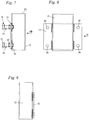
- Fig. 1 shows schematically a facade panel arrangement 1 with an upper facade panel 2 and a lower facade panel 3.
- the upper facade panel 2 is arranged above the lower facade panel 3 at a small distance from the lower facade panel 3.
- the facade panels 2 and 3 are in Fig. 1 not shown fixed support structure.
- the facade panels 2 and 3 are aligned in a vertical direction y, which is advantageously vertical.
- an inclined arrangement of the supporting structure and the facade panels 2 and 3 can also be provided.
- a pinning system 4 is provided for positioning the facade panels 2 and 3 and fixing the facade panels 2 and 3 to one another in a depth direction z which is oriented perpendicular to the plane of the facade panels 2 and 3.
- the pinning system 4 comprises a pin 5 which is guided in a guide 6.
- the pin 5 has a longitudinal center axis 9.
- the guide 6 guides the pin 5 in the direction of the longitudinal center axis 9.
- the pin 5 is guided in the guide 6 so as to be displaceable in the direction of its longitudinal center axis 9.
- the pin 5 in the guide 6 is not movable within the scope of the usual manufacturing tolerances.
- the pin 5 can be moved in the direction of its longitudinal center axis 9 and in the lateral direction x in a guide 6 ′ and is not movably guided in the depth direction z.
- the guide 6 'is in Fig. 2 drawn in with a dashed line.
- the guide 6 ' is designed as an elongated hole in cross section. A design with an oval cross section can also be advantageous.
- Fig. 1 shows the arrangement in a neutral position, which corresponds to an advantageous installation position.
- the guide 6 has, in the area arranged in the neutral position below the pin 5, means for fixing the pin 5 in the guide 6, which prevent the pin 5 from slipping in the receptacle 6 during assembly.
- the means for fixing the pin 5 advantageously reduce the free cross section of the guide 6.
- a conical section 61 in which the inner diameter of the guide 6 decreases conically, is provided for fixing the pin 5.
- the means for fixing the pin 5 can comprise beads, webs or the like in the guide 6.
- the pin 5 and the guide 6 are each held on the associated facade panel 2, 3 via an anchoring device 7, 8.
- the pin 5 is fixed on the upper facade panel 2.
- the pin 5 is welded to a fastening plate 18.
- the fastening plate 18 is fixed to the anchoring device 7.
- the anchoring device 7 is cast into the facade panel 2.
- the facade panel 2 is designed as a concrete slab in the exemplary embodiment and in particular has reinforcement 36, which is shown in FIG Fig. 1 is shown schematically. No reinforcement 36 is shown in the other figures. Reinforcement 36 can be advantageous in all of the exemplary embodiments.
- the reinforcement 36 is in particular a textile, stainless steel and / or fiber reinforcement.
- the reinforcement 36 is a textile reinforcement, in particular made of glass fiber reinforced plastic (GRP).
- GRP glass fiber reinforced plastic
- the reinforcement 36 is a single-layer, central reinforcement. It can also be advantageous for the reinforcement to be arranged eccentrically and / or to have multiple layers and / or to consist of fibers.
- the anchoring device 7 has potting anchors 14, each of which comprises a screw 21 and a nut 22 screwed onto the screw 21.
- the heads of the screws 21 form undercuts in the material of the facade panel 2, so that good anchoring is achieved.
- the anchoring device 7 also comprises a potting plate 13 through which the bolts 21 forming the potting anchors 14 protrude.
- the screws 21 are including the nuts 22 and the Potting plate 13 embedded in the facade plate 2. Only the free ends of the screws 21 protruding beyond the potting plate 13 protrude from the facade plate 2.
- the end faces of the nuts 22 form a contact surface for the potting plate 13.
- the potting plate 13 is flush with an inner side 20 of the facade plate 2.
- the inner side 20 is one The side of the facade panel 2 facing the supporting structure.
- the grouting anchors 14 do not protrude as far as an outer side 19 of the facade panel 2 facing away from the inner side 20 and the supporting structure arranged, which serve to position the fastening plate 18 and define the distance between the inside 20 of the facade panel 2 and the fastening plate 18.
- fastening nuts 15 screwed onto the screws 21 are provided.
- the guide 6 is also connected to an anchoring device 8.
- the anchoring device 8 comprises potting anchor 14 and a potting plate 13.
- the design of the anchoring device 8 corresponds to the design of the anchoring device 7.
- a pocket 12 is fixed on the potting plate 13, welded in the exemplary embodiment.
- the pocket 12 forms a receptacle for potting compound 11.
- the guide 6 is formed in a guide sleeve 10 which is cast in the potting compound 11. During assembly, the guide sleeve 10 is first positioned on the pin 5 and then lowered into the potting compound 11 when the upper facade panel 2 is lowered to the lower facade panel 3. The guide sleeve is then positioned in the poured-out pocket 12.
- the upper facade panel 2 has an underside 25 which faces the lower facade panel 3.
- the lower facade panel 3 has an upper side 24 facing the upper facade panel 2.
- the anchoring device 7 of the upper facade panel 2 is embedded in the material of the upper facade panel 2 at an edge distance h from the underside 25.
- the anchoring device 8 of the lower facade panel 3 has an edge distance h 'from the top 24.
- the pocket 12 protrudes with its upper edge 23 up to the upper side 24 of the lower facade panel 3.
- the pocket 12 accordingly ends flush with the upper side 24 of the lower facade panel 3 in the exemplary embodiment.
- the longitudinal center axis 9 of the pin 5 is arranged at a distance i from the inside 20 of the facade panels 2 and 3.
- the longitudinal center axis 9 is aligned parallel to the inside 20 and advantageously vertically in the installed state.
- the facade panels 2 and 3 are designed as thin facade panels.
- the facade panels 2 and 3 have a thickness a which is less than 50 mm, in particular less than 40 mm. In the exemplary embodiment, the thickness a is approximately 30 mm.
- the thickness a is measured in the depth direction z. In the exemplary embodiment, the distance i is somewhat smaller than the thickness a.
- the pin 5 has an outer diameter g which is advantageously at least 20%, in particular at least 30%, in the exemplary embodiment approximately 50% of the thickness a.
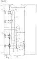
- Fig. 2 the arrangement of the guide sleeve 10 in the pocket 12 is shown in detail.
- the inside of the pocket 12 has a depth b, measured in the depth direction z, which is greater than 75% of the thickness a of the facade panels 2 and 3.
- the pocket 12 also has a width c, measured in the lateral direction x, which is also greater than the thickness a of the facade panel 3. In the exemplary embodiment, the width c is greater than the depth b.
- the guide sleeve 10 has an outer diameter d.
- the outer diameter d is advantageously at least 20%, in particular at least 30% of the thickness a of the facade panel 3 ( Fig. 1 ).
- the outer diameter d can advantageously be approximately 50% of the thickness a of the facade panel 3. How Fig.
- the guide sleeve 10 in the neutral position shown has a distance e to the inner walls of the pocket 12 in the depth direction z both on the side facing the facade panel 3 and on the side facing away from the facade panel 3.
- the distance e is advantageously between 5 mm and 15 mm in the neutral position.
- the position of the guide sleeve 10 in the depth direction z can be adjusted by at least 5 mm in each direction.
- the distance e corresponds to half the difference between the depth b and the outer knife d.
- the guide sleeve 10 has a distance f to both inner sides of the pocket 12.
- the distance f corresponds to half the difference between the width c and the outer diameter d.
- the distance f is greater than the distance e.
- the distance f is advantageously at least 10 mm.
- the grouting anchors 14 protrude over a depth p from the inside 20 of the facade panel 3 into the facade panel 3.
- the depth p is advantageously at least half, in particular at least 75% of the thickness a of the facade panel 3.
- the casting anchors 14 extend over at least 50%, in particular at least 75% of the thickness a of the upper facade panel 2.
- the anchoring devices 7 and 8 advantageously protrude over at least half, in particular over at least 75% of the thickness a of the associated facade panel 2, 3 from the inside 20 in the facade panel 2, 3.
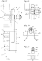
- Fig. 3 shows the fixing of the pin 5 to the potting anchors 14.
- the potting anchors 14 form an assembly with the pin 5.
- the fastening plate 18 to which the pin 5 is fixed welded in the exemplary embodiment, can be fixed to the anchoring device via the nuts 15 after the anchoring device 7 has been poured into the facade panel 2.
- the fastening plate 18 has four openings 27 for the passage of the screws 21, which form the potting anchor 14. Accordingly, four potting anchors 14 are provided.
- Fig. 5 shows the welded connection between the pin 5 and the fastening plate 18.
- Fig. 6 shows the fastening plate 18 with the openings 27 without the pin 5 welded to it.
- Fig. 7 shows the second anchoring device 8 with the pocket 12 arranged thereon.
- the pocket 12 is welded directly to the potting plate 13, as is the case Figures 8 and 9 demonstrate.
- the potting plate 13 has four openings 26 for the passage of the screws 21.
- the anchoring device 8 accordingly also has four potting anchors.
- the pocket 12 protrudes beyond the potting plate 13, namely by the distance h '( Fig. 1 ), so that the upper edge 23 of the pocket 12 lies flush with the upper side 24 of the facade panel 3 in the installed state.
- Another distance h ′ can also be advantageous, so that the upper edge 23 of the pocket 12 lies above or below the upper side 24 of the facade panel 3 in the installed state.
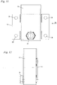
- Fig. 10 shows an alternative embodiment, which is essentially the embodiment according to Figures 1 to 9 corresponds to.
- the same reference symbols denote elements that correspond to one another in all figures.
- the pin 5 is fixed to the upper facade panel 2 via an anchoring device 7.
- the pocket 12 is fixed to the lower facade panel 3 via a second anchoring device 8.
- the guide 6 is formed on the guide sleeve 10.
- the support structure 31 is also shown.
- the support structure 31 is arranged at a distance k, measured in the depth direction z, from the inner sides 20 of the facade panels 2, 3.
- an intermediate space 35 is formed between the facade panels 2, 3 and the supporting structure 31, into which the pinning arrangement 4 protrudes. How Fig.
- the pocket 12 has a distance m from the support structure 31, which in the exemplary embodiment is 30% to 70% of the distance k.
- the distance m is bridged by a support device 33.
- the facade panels 2, 3 are supported on the support structure 31 in the horizontal direction, that is to say in the depth direction z, via the support device 33.
- the support device 33 comprises an adjusting nut 30, which is firmly fixed on the side of the pocket 12 facing the support structure 31 and facing away from the facade panel 3.
- the adjusting nut 30 is arranged on the pocket 12 away from the upper side 23 of the pocket 12.
- a support screw 28 protrudes through the adjusting nut 30 with its end 32 into the interior of the pocket 12.
- the screw 28 has a head 29 which rests on the support structure 31 and thereby supports the facade panel 3 on the support structure 31. Due to the pinning device 4, horizontal forces can also be introduced into the support structure 31 from the upper facade panel 2 via the support device 33.
- the support device 33 namely the support screw 28, has a longitudinal center axis 34, which is preferably oriented horizontally in the depth direction z, that is, perpendicular to the outside of the support structure 31. Since the head 29 of the support screw 28 is only in contact with the support structure 31, only forces in the horizontal direction can be introduced into the support structure 31 via the support device 33. Vertical forces are introduced into the support structure 31 via suitable fastening devices (not shown).
- the adjusting nut 30 is fixed to the pocket 12 via a welded connection.
- a different way of fixing the adjusting nut 30 can also be advantageous.
- the pocket 12 has an in Fig. 12 schematically shown opening through which the support screw 28 ( Fig. 10 ) can protrude into the interior of the pocket 21.
- Another adjustable support device can also be advantageous.
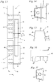
- Fig. 13 shows a further embodiment of the facade panel arrangement 1.
- the guide 6 is fixed to the upper facade panel 2.
- the guide 6 is formed in a guide sleeve 10 which is fixed to the upper facade panel 2 by means of potting compound 11.
- the pin 5 protrudes into a pocket 12 which is arranged on the lower facade panel 3 and which is filled with potting compound 11.
- the pin 5 is held on the lower facade panel 3 by means of potting compound 11.
- the pocket 12 is delimited in the horizontal direction by a sheet metal part 39 which is in the Figures 15 and 16 is shown.
- the sheet metal part 39 is bent approximately in a U-shape and forms two side walls 45 and a rear wall 46 of the pocket 12.
- the rear wall 46 faces away from the facade panel 3.
- the side walls 45 connect the inside 20 of the facade panel 3 to the rear wall 46.
- the pocket 12 is on the The rear wall 46 is closed by the side facing away from the inside 20 of the facade panel 3.
- anchoring elements 40 are formed, which protrude into the facade panel 3, as well Fig. 13 shows. How Fig. 16 shows, five anchoring elements 40 are provided on each side wall 45 in the exemplary embodiment. A different number of anchoring elements 40 can also be advantageous.
- the anchoring elements 40 are designed as individual fingers spaced apart from one another, which in the exemplary embodiment are each provided with three bends 47. The bends 47 result in the anchoring elements 40 facing the depth direction z ( Fig. 13 ) are curved and thereby form an undercut in the concrete of the facade panel 3.
- the pocket 12 is closed at the bottom, that is to say on the side facing away from the guide 6, at least partially by a base 41.
- the bottom 41 can be designed, for example, as a plastic injection-molded part or a metal part.
- the bottom 41 has, like that Figures 14 and 17 show a circumferential wall 42 and holding webs 43 arranged at a distance from the circumferential wall 42.
- the sheet metal part 39 is held between the circumferential wall 42 and the holding webs 43, preferably held in a clamped manner.
- a circular predetermined breaking point 44 is formed on the bottom 17.
- the predetermined breaking point 44 can be formed, for example, by material with a smaller wall thickness.
- an opening 55 is created in the bottom 41, which is shown in FIG Fig. 13 is shown on the upper pocket 12.
- the guide sleeve 10 with the pin 5 arranged therein protrudes through the opening 55.
- the guide sleeve 10 can also be fixed on the bottom 41 of the upper pocket 12.
- the lower pocket 12 is completely closed at the bottom by the bottom 41.
- the guide sleeve 10 is fixed to the upper facade panel 2.
- the guide sleeve 10 protrudes through the opening 55 in a pocket 12 corresponding to Pocket 12 is formed on the lower facade panel 3.
- the opening 55 is provided only in the base 41.
- the guide sleeve 10 is fixed in the pocket 12 by means of potting compound 11.
- the pocket 12 is formed by the sheet metal part 39 and the floor 41 and is fixed to the facade panel 2 via anchoring elements 40 which protrude into the facade panel 2 and are concreted into it.
- the anchoring devices 7 and 8 and the pockets 12 for fixing the pin 5 or for fixing the guide sleeve 10 can thus be of identical design except for the opening 55.
- the pockets 12 are made from the same components.
- Fig. 18 shows an alternative embodiment of a facade panel arrangement 1 with a pinning system 4.
- a pocket 12 which corresponds to the pocket 12 in the previous exemplary embodiment, is arranged on the lower facade panel 3.
- the pocket 12 is formed from a sheet metal part 39 and a base 41.
- the sheet metal part 39 protrudes with anchoring elements 40 into the facade panel 3.
- the guide 6 for the pin 5 is formed on a guide sleeve 10, which is designed as a ring.
- the upper end of the pin 5 protrudes upward out of the guide sleeve 10.
- the guide sleeve 10 is fixed via a screw connection 48 to a sheet metal part 49 which has two anchoring elements 40 which are cast in the material of the upper facade panel 2.
- the sheet metal part 49 corresponds approximately in its design to the sheet metal part 39, but is made shorter.
- the design of the sheet metal part 49 is in particular in Fig. 20 shown.
- a screw 59 is fixed to the guide sleeve 10, welded in the exemplary embodiment.
- the longitudinal axis of the screw 59 is transverse to the longitudinal center axis 9 of the pin 5 ( Fig. 18 ) aligned.
- the longitudinal axis of the screw 59 runs in the depth direction z.
- the screw 59 protrudes with its threaded bolt through an opening in the sheet metal part 49 onto the side of the sheet metal part 49 facing away from the facade panel 2. On this side, the screw 59 is screwed into a nut 60, as Fig. 19 shows.
- the nut 60 is fixed to the sheet metal part 49, for example via a welded connection.
- the guide 6 has an inner diameter o.
- a cap 50 is placed on the pin 5, which is shown in FIG Fig. 19 is shown.
- the cap 50 is advantageously held on the pin 5 in a form-fitting manner.
- the cap 50 has an outer diameter n which is greater than the inner diameter o of the guide 6.
- FIGS 20 and 21 show an exemplary embodiment with a shortened length of the screw 59.
- the structure of the arrangement is the same as in FIG Figures 18 and 19 so that the same reference numerals are used.
- the Figures 22 to 25 show a further exemplary embodiment of a facade panel arrangement 1 with a pinning system 4.
- a pin 5 is fixed to the lower facade panel 3.
- the pin 5 is held in a pocket 12 via potting compound 11.
- the pocket 12 is delimited by a molded part 52, which can be a plastic component, for example.
- a reinforcement 51 protrudes into the facade panel 3 and into the potting compound 11. Forces are transmitted from the potting compound 11 into the facade panel 3 via the reinforcement 51. Because the power transmission does not take place via the molded part 52, it does not have to be able to absorb large forces.
- the molded part 52 serves only as a casting mold for the casting compound 11 in the production of the facade panel arrangement 1.
- the molded part 52 is closed at the bottom by a base 54.
- a guide sleeve 10 is fixed in a corresponding manner on the upper facade panel 2.
- the pocket 12 has an opening 55 which is provided in a bottom 54 of the molded part 52.
- Fig. 23 shows the arrangement before the potting compound is poured in.
- the reinforcement 51 protrudes into the facade panel 2 and the pocket 12.
- the molded part 52 can be cast into the facade panel 2 on its side facing the facade panel 2. Another way of fixing the molded part 52 to the facade panel 2 can also be advantageous.
- fixation projections 56 are formed on the molded part 52, which protrude into the interior of the pocket 12 and on which the reinforcement 51 is held.
- the molded part 52 is thereby fixed to the respective facade panel 2, 3 via the reinforcement 51.
- Fig. 24 shows a pocket 12 which is designed for arrangement on a lower facade panel 3.
- the bottom 54 is designed as a continuous surface.
- Fig. 25 shows a molded part 52 which is provided for arrangement on the upper facade panel 2 or on the lower facade panel 3.
- a predetermined breaking point 53 is provided, which is circular in the embodiment. At the predetermined breaking point 53, material of the bottom 54 can be broken out to remove the in Fig. 22 To create the opening 55 shown for the guide sleeve 10 or a corresponding opening for the pin 5 when the pin 5 is fixed to the upper facade panel 2.
- the guide sleeve 10 is fixed on the bottom 54 of the molded part 52 of the upper facade panel 2.
- the same reference symbols denote elements that correspond to one another. Further advantageous exemplary embodiments result from any combination of the features of the individual exemplary embodiments with one another.
- the pin 5 can be arranged in an alternative design in a guide 6 ′, which allows movements in the horizontal direction parallel to the plane of the facade panels 2, 3.
Landscapes
- Engineering & Computer Science (AREA)
- Architecture (AREA)
- General Engineering & Computer Science (AREA)
- Civil Engineering (AREA)
- Structural Engineering (AREA)
- Mechanical Engineering (AREA)
- Chemical & Material Sciences (AREA)
- Ceramic Engineering (AREA)
- Joining Of Building Structures In Genera (AREA)
Priority Applications (2)
| Application Number | Priority Date | Filing Date | Title |
|---|---|---|---|
| PL17000066T PL3348746T3 (pl) | 2017-01-13 | 2017-01-13 | Układ płyt elewacyjnych |
| EP17000066.5A EP3348746B1 (de) | 2017-01-13 | 2017-01-13 | Fassadenplattenanordnung |
Applications Claiming Priority (1)
| Application Number | Priority Date | Filing Date | Title |
|---|---|---|---|
| EP17000066.5A EP3348746B1 (de) | 2017-01-13 | 2017-01-13 | Fassadenplattenanordnung |
Publications (2)
| Publication Number | Publication Date |
|---|---|
| EP3348746A1 EP3348746A1 (de) | 2018-07-18 |
| EP3348746B1 true EP3348746B1 (de) | 2021-04-14 |
Family
ID=57850873
Family Applications (1)
| Application Number | Title | Priority Date | Filing Date |
|---|---|---|---|
| EP17000066.5A Active EP3348746B1 (de) | 2017-01-13 | 2017-01-13 | Fassadenplattenanordnung |
Country Status (2)
| Country | Link |
|---|---|
| EP (1) | EP3348746B1 (pl) |
| PL (1) | PL3348746T3 (pl) |
Cited By (2)
| Publication number | Priority date | Publication date | Assignee | Title |
|---|---|---|---|---|
| US20240060310A1 (en) * | 2021-02-23 | 2024-02-22 | Metalline (Services) Ltd. | A multipart bracket and rainscreen cladding mount system including same |
| US12497781B2 (en) * | 2021-02-23 | 2025-12-16 | Metalline (Services) Ltd. | Multipart bracket and rainscreen cladding mount system including same |
Families Citing this family (2)
| Publication number | Priority date | Publication date | Assignee | Title |
|---|---|---|---|---|
| CN110965722A (zh) * | 2018-09-28 | 2020-04-07 | 台山市长发木业有限公司 | 一种固定装饰板材的嵌缝装置 |
| CN109235735B (zh) * | 2018-11-06 | 2024-03-15 | 苏州金螳螂建筑装饰股份有限公司 | 一种应用于商场中庭的树脂板以及与其相适配的吊装结构 |
Family Cites Families (4)
| Publication number | Priority date | Publication date | Assignee | Title |
|---|---|---|---|---|
| DE1942604A1 (de) * | 1969-08-21 | 1971-02-25 | Vogel Uwe Dipl Ing | Einrichtung zum Verankern eines Teiles an einem anderen Teil eines Baukoerpers |
| DE59605599D1 (de) * | 1996-10-16 | 2000-08-17 | Siegfried Hoefle | Fassadenbefestigungselement |
| JP2004003128A (ja) * | 2002-05-10 | 2004-01-08 | Tostem Corp | 建物外装用パネルの取り付け構造 |
| KR101324726B1 (ko) * | 2012-07-30 | 2013-11-05 | 최서윤 | 건축 내외장재 설치용 고정구 |
-
2017
- 2017-01-13 PL PL17000066T patent/PL3348746T3/pl unknown
- 2017-01-13 EP EP17000066.5A patent/EP3348746B1/de active Active
Non-Patent Citations (1)
| Title |
|---|
| None * |
Cited By (2)
| Publication number | Priority date | Publication date | Assignee | Title |
|---|---|---|---|---|
| US20240060310A1 (en) * | 2021-02-23 | 2024-02-22 | Metalline (Services) Ltd. | A multipart bracket and rainscreen cladding mount system including same |
| US12497781B2 (en) * | 2021-02-23 | 2025-12-16 | Metalline (Services) Ltd. | Multipart bracket and rainscreen cladding mount system including same |
Also Published As
| Publication number | Publication date |
|---|---|
| PL3348746T3 (pl) | 2021-11-22 |
| EP3348746A1 (de) | 2018-07-18 |
Similar Documents
| Publication | Publication Date | Title |
|---|---|---|
| EP2875193B1 (de) | Montage einer wandschalung und ankersystem mit rastermass | |
| EP2678571B1 (de) | Eckverbinder für hohlprofile | |
| EP1146180A1 (de) | Verfahren zur Herstellung eines Beton-Deckenelements und Beton-Deckenelement | |
| EP2557243A2 (de) | Bauelement zur Wärmedämmung | |
| EP2166178A2 (de) | Abstandhalter | |
| DE102011088456B4 (de) | Anordnung mit Positionierungselement zum Positionieren zumindest eines stabförmigen Bewehrungselementes | |
| EP3789550A1 (de) | Rostverriegelungsvorrichtung | |
| EP0328484A1 (de) | Gleithülse zur Aufnahme eines Querkraftdornes | |
| EP0410079B1 (de) | Anschlussschalung für aneinander anschliessende Betonplatten | |
| EP3348746B1 (de) | Fassadenplattenanordnung | |
| EP3744895B1 (de) | Verfahren zur herstellung einer verkehrsfläche, verkehrsfläche und fertigbetonplatte | |
| EP2022909B1 (de) | Seilschlaufenkasten | |
| EP2375522A2 (de) | Installationsdose für elektrotechnische Zwecke | |
| DE102007059049A1 (de) | Anordnung zur Lagesicherung einer Befestigungsschraube an einer Profilschiene sowie Bauteil hierfür | |
| DE2832295A1 (de) | Formtisch fuer betonfertigplatten | |
| EP3263787B1 (de) | Fertigbetonbauteil, insbesondere fertigbetonplatte, transportanker für ein solches fertigbetonbauteil | |
| EP3839162B1 (de) | Thermisch isolierendes bauelement zum einsatz in einer trennfuge zwischen zwei bauwerksteilen | |
| DE102018010372A1 (de) | Rostverriegelungsvorrichtung für einen Rost einer Entwässerungsrinne sowie höhenverstellbare Entwässerungsrinne | |
| DE10038852A1 (de) | Vorrichtung zur kraftschlüssigen Befestigung einer Konsole an einem Trägergrundkörper | |
| DE102013208572A1 (de) | Vorrichtung zur Herstellung von Bauteilen aus Beton | |
| DE102023108359A1 (de) | Thermisch isolierendes Bauelement, Gebäudeabschnitt und Verfahren zum Einbau eines thermisch isolierenden Bauelementes | |
| DE3502415A1 (de) | Einrichtung und verfahren zur herstellung von schalungseinheiten | |
| EP4256209B1 (de) | System zur befestigung einer schiene und verfahren zur reparatur | |
| DE102006000816B3 (de) | Führungsschiene für den Umlenkbeschlag eines Sicherheitsgurtes für Kraftfahrzeuge | |
| EP3348742A1 (de) | Abstützvorrichtung zur abstützung einer fassadenplatte an einer tragstruktur |
Legal Events
| Date | Code | Title | Description |
|---|---|---|---|
| PUAI | Public reference made under article 153(3) epc to a published international application that has entered the european phase |
Free format text: ORIGINAL CODE: 0009012 |
|
| STAA | Information on the status of an ep patent application or granted ep patent |
Free format text: STATUS: THE APPLICATION HAS BEEN PUBLISHED |
|
| AK | Designated contracting states |
Kind code of ref document: A1 Designated state(s): AL AT BE BG CH CY CZ DE DK EE ES FI FR GB GR HR HU IE IS IT LI LT LU LV MC MK MT NL NO PL PT RO RS SE SI SK SM TR |
|
| AX | Request for extension of the european patent |
Extension state: BA ME |
|
| STAA | Information on the status of an ep patent application or granted ep patent |
Free format text: STATUS: REQUEST FOR EXAMINATION WAS MADE |
|
| 17P | Request for examination filed |
Effective date: 20181108 |
|
| RBV | Designated contracting states (corrected) |
Designated state(s): AL AT BE BG CH CY CZ DE DK EE ES FI FR GB GR HR HU IE IS IT LI LT LU LV MC MK MT NL NO PL PT RO RS SE SI SK SM TR |
|
| STAA | Information on the status of an ep patent application or granted ep patent |
Free format text: STATUS: EXAMINATION IS IN PROGRESS |
|
| 17Q | First examination report despatched |
Effective date: 20190403 |
|
| REG | Reference to a national code |
Ref country code: DE Ref legal event code: R079 Ref document number: 502017010041 Country of ref document: DE Free format text: PREVIOUS MAIN CLASS: E04F0013140000 Ipc: F16B0005020000 |
|
| GRAP | Despatch of communication of intention to grant a patent |
Free format text: ORIGINAL CODE: EPIDOSNIGR1 |
|
| STAA | Information on the status of an ep patent application or granted ep patent |
Free format text: STATUS: GRANT OF PATENT IS INTENDED |
|
| RIC1 | Information provided on ipc code assigned before grant |
Ipc: F16B 5/00 20060101ALI20200706BHEP Ipc: F16B 5/02 20060101AFI20200706BHEP Ipc: F16B 19/02 20060101ALI20200706BHEP Ipc: E04F 13/14 20060101ALI20200706BHEP Ipc: E04C 2/04 20060101ALI20200706BHEP Ipc: E04F 13/08 20060101ALI20200706BHEP |
|
| INTG | Intention to grant announced |
Effective date: 20200727 |
|
| RIN1 | Information on inventor provided before grant (corrected) |
Inventor name: DREIKLUFT, NORBERT Inventor name: HERRNKIND, VOLKER |
|
| GRAJ | Information related to disapproval of communication of intention to grant by the applicant or resumption of examination proceedings by the epo deleted |
Free format text: ORIGINAL CODE: EPIDOSDIGR1 |
|
| STAA | Information on the status of an ep patent application or granted ep patent |
Free format text: STATUS: EXAMINATION IS IN PROGRESS |
|
| GRAP | Despatch of communication of intention to grant a patent |
Free format text: ORIGINAL CODE: EPIDOSNIGR1 |
|
| STAA | Information on the status of an ep patent application or granted ep patent |
Free format text: STATUS: GRANT OF PATENT IS INTENDED |
|
| INTC | Intention to grant announced (deleted) | ||
| INTG | Intention to grant announced |
Effective date: 20201111 |
|
| GRAS | Grant fee paid |
Free format text: ORIGINAL CODE: EPIDOSNIGR3 |
|
| GRAA | (expected) grant |
Free format text: ORIGINAL CODE: 0009210 |
|
| STAA | Information on the status of an ep patent application or granted ep patent |
Free format text: STATUS: THE PATENT HAS BEEN GRANTED |
|
| AK | Designated contracting states |
Kind code of ref document: B1 Designated state(s): AL AT BE BG CH CY CZ DE DK EE ES FI FR GB GR HR HU IE IS IT LI LT LU LV MC MK MT NL NO PL PT RO RS SE SI SK SM TR |
|
| REG | Reference to a national code |
Ref country code: GB Ref legal event code: FG4D Free format text: NOT ENGLISH |
|
| REG | Reference to a national code |
Ref country code: CH Ref legal event code: EP |
|
| REG | Reference to a national code |
Ref country code: DE Ref legal event code: R096 Ref document number: 502017010041 Country of ref document: DE |
|
| REG | Reference to a national code |
Ref country code: IE Ref legal event code: FG4D Free format text: LANGUAGE OF EP DOCUMENT: GERMAN |
|
| REG | Reference to a national code |
Ref country code: AT Ref legal event code: REF Ref document number: 1382637 Country of ref document: AT Kind code of ref document: T Effective date: 20210515 |
|
| REG | Reference to a national code |
Ref country code: NL Ref legal event code: FP |
|
| REG | Reference to a national code |
Ref country code: SE Ref legal event code: TRGR |
|
| REG | Reference to a national code |
Ref country code: LT Ref legal event code: MG9D |
|
| PG25 | Lapsed in a contracting state [announced via postgrant information from national office to epo] |
Ref country code: LT Free format text: LAPSE BECAUSE OF FAILURE TO SUBMIT A TRANSLATION OF THE DESCRIPTION OR TO PAY THE FEE WITHIN THE PRESCRIBED TIME-LIMIT Effective date: 20210414 Ref country code: FI Free format text: LAPSE BECAUSE OF FAILURE TO SUBMIT A TRANSLATION OF THE DESCRIPTION OR TO PAY THE FEE WITHIN THE PRESCRIBED TIME-LIMIT Effective date: 20210414 Ref country code: HR Free format text: LAPSE BECAUSE OF FAILURE TO SUBMIT A TRANSLATION OF THE DESCRIPTION OR TO PAY THE FEE WITHIN THE PRESCRIBED TIME-LIMIT Effective date: 20210414 Ref country code: BG Free format text: LAPSE BECAUSE OF FAILURE TO SUBMIT A TRANSLATION OF THE DESCRIPTION OR TO PAY THE FEE WITHIN THE PRESCRIBED TIME-LIMIT Effective date: 20210714 |
|
| PG25 | Lapsed in a contracting state [announced via postgrant information from national office to epo] |
Ref country code: NO Free format text: LAPSE BECAUSE OF FAILURE TO SUBMIT A TRANSLATION OF THE DESCRIPTION OR TO PAY THE FEE WITHIN THE PRESCRIBED TIME-LIMIT Effective date: 20210714 Ref country code: PT Free format text: LAPSE BECAUSE OF FAILURE TO SUBMIT A TRANSLATION OF THE DESCRIPTION OR TO PAY THE FEE WITHIN THE PRESCRIBED TIME-LIMIT Effective date: 20210816 Ref country code: RS Free format text: LAPSE BECAUSE OF FAILURE TO SUBMIT A TRANSLATION OF THE DESCRIPTION OR TO PAY THE FEE WITHIN THE PRESCRIBED TIME-LIMIT Effective date: 20210414 Ref country code: LV Free format text: LAPSE BECAUSE OF FAILURE TO SUBMIT A TRANSLATION OF THE DESCRIPTION OR TO PAY THE FEE WITHIN THE PRESCRIBED TIME-LIMIT Effective date: 20210414 Ref country code: GR Free format text: LAPSE BECAUSE OF FAILURE TO SUBMIT A TRANSLATION OF THE DESCRIPTION OR TO PAY THE FEE WITHIN THE PRESCRIBED TIME-LIMIT Effective date: 20210715 Ref country code: IS Free format text: LAPSE BECAUSE OF FAILURE TO SUBMIT A TRANSLATION OF THE DESCRIPTION OR TO PAY THE FEE WITHIN THE PRESCRIBED TIME-LIMIT Effective date: 20210814 |
|
| REG | Reference to a national code |
Ref country code: DE Ref legal event code: R097 Ref document number: 502017010041 Country of ref document: DE |
|
| REG | Reference to a national code |
Ref country code: DE Ref legal event code: R081 Ref document number: 502017010041 Country of ref document: DE Owner name: LEVIAT GMBH, DE Free format text: FORMER OWNER: HALFEN GMBH, 40764 LANGENFELD, DE |
|
| PG25 | Lapsed in a contracting state [announced via postgrant information from national office to epo] |
Ref country code: EE Free format text: LAPSE BECAUSE OF FAILURE TO SUBMIT A TRANSLATION OF THE DESCRIPTION OR TO PAY THE FEE WITHIN THE PRESCRIBED TIME-LIMIT Effective date: 20210414 Ref country code: DK Free format text: LAPSE BECAUSE OF FAILURE TO SUBMIT A TRANSLATION OF THE DESCRIPTION OR TO PAY THE FEE WITHIN THE PRESCRIBED TIME-LIMIT Effective date: 20210414 Ref country code: CZ Free format text: LAPSE BECAUSE OF FAILURE TO SUBMIT A TRANSLATION OF THE DESCRIPTION OR TO PAY THE FEE WITHIN THE PRESCRIBED TIME-LIMIT Effective date: 20210414 Ref country code: RO Free format text: LAPSE BECAUSE OF FAILURE TO SUBMIT A TRANSLATION OF THE DESCRIPTION OR TO PAY THE FEE WITHIN THE PRESCRIBED TIME-LIMIT Effective date: 20210414 Ref country code: ES Free format text: LAPSE BECAUSE OF FAILURE TO SUBMIT A TRANSLATION OF THE DESCRIPTION OR TO PAY THE FEE WITHIN THE PRESCRIBED TIME-LIMIT Effective date: 20210414 Ref country code: SM Free format text: LAPSE BECAUSE OF FAILURE TO SUBMIT A TRANSLATION OF THE DESCRIPTION OR TO PAY THE FEE WITHIN THE PRESCRIBED TIME-LIMIT Effective date: 20210414 Ref country code: SK Free format text: LAPSE BECAUSE OF FAILURE TO SUBMIT A TRANSLATION OF THE DESCRIPTION OR TO PAY THE FEE WITHIN THE PRESCRIBED TIME-LIMIT Effective date: 20210414 |
|
| PLBE | No opposition filed within time limit |
Free format text: ORIGINAL CODE: 0009261 |
|
| STAA | Information on the status of an ep patent application or granted ep patent |
Free format text: STATUS: NO OPPOSITION FILED WITHIN TIME LIMIT |
|
| RAP4 | Party data changed (patent owner data changed or rights of a patent transferred) |
Owner name: LEVIAT GMBH |
|
| 26N | No opposition filed |
Effective date: 20220117 |
|
| REG | Reference to a national code |
Ref country code: BE Ref legal event code: HC Owner name: LEVIAT GMBH; DE Free format text: DETAILS ASSIGNMENT: CHANGE OF OWNER(S), CHANGE OF OWNER(S) NAME; FORMER OWNER NAME: HALFEN GMBH Effective date: 20220211 |
|
| REG | Reference to a national code |
Ref country code: NL Ref legal event code: PD Owner name: LEVIAT GMBH; DE Free format text: DETAILS ASSIGNMENT: CHANGE OF OWNER(S), MERGE; FORMER OWNER NAME: HALFEN GMBH Effective date: 20220316 |
|
| REG | Reference to a national code |
Ref country code: AT Ref legal event code: HC Ref document number: 1382637 Country of ref document: AT Kind code of ref document: T Owner name: LEVIAT GMBH, DE Effective date: 20220406 |
|
| PG25 | Lapsed in a contracting state [announced via postgrant information from national office to epo] |
Ref country code: IS Free format text: LAPSE BECAUSE OF FAILURE TO SUBMIT A TRANSLATION OF THE DESCRIPTION OR TO PAY THE FEE WITHIN THE PRESCRIBED TIME-LIMIT Effective date: 20210814 Ref country code: AL Free format text: LAPSE BECAUSE OF FAILURE TO SUBMIT A TRANSLATION OF THE DESCRIPTION OR TO PAY THE FEE WITHIN THE PRESCRIBED TIME-LIMIT Effective date: 20210414 |
|
| PG25 | Lapsed in a contracting state [announced via postgrant information from national office to epo] |
Ref country code: MC Free format text: LAPSE BECAUSE OF FAILURE TO SUBMIT A TRANSLATION OF THE DESCRIPTION OR TO PAY THE FEE WITHIN THE PRESCRIBED TIME-LIMIT Effective date: 20210414 |
|
| PG25 | Lapsed in a contracting state [announced via postgrant information from national office to epo] |
Ref country code: LU Free format text: LAPSE BECAUSE OF NON-PAYMENT OF DUE FEES Effective date: 20220113 |
|
| PG25 | Lapsed in a contracting state [announced via postgrant information from national office to epo] |
Ref country code: IE Free format text: LAPSE BECAUSE OF NON-PAYMENT OF DUE FEES Effective date: 20220113 |
|
| PG25 | Lapsed in a contracting state [announced via postgrant information from national office to epo] |
Ref country code: HU Free format text: LAPSE BECAUSE OF FAILURE TO SUBMIT A TRANSLATION OF THE DESCRIPTION OR TO PAY THE FEE WITHIN THE PRESCRIBED TIME-LIMIT; INVALID AB INITIO Effective date: 20170113 |
|
| PG25 | Lapsed in a contracting state [announced via postgrant information from national office to epo] |
Ref country code: MK Free format text: LAPSE BECAUSE OF FAILURE TO SUBMIT A TRANSLATION OF THE DESCRIPTION OR TO PAY THE FEE WITHIN THE PRESCRIBED TIME-LIMIT Effective date: 20210414 Ref country code: CY Free format text: LAPSE BECAUSE OF FAILURE TO SUBMIT A TRANSLATION OF THE DESCRIPTION OR TO PAY THE FEE WITHIN THE PRESCRIBED TIME-LIMIT Effective date: 20210414 |
|
| PG25 | Lapsed in a contracting state [announced via postgrant information from national office to epo] |
Ref country code: TR Free format text: LAPSE BECAUSE OF FAILURE TO SUBMIT A TRANSLATION OF THE DESCRIPTION OR TO PAY THE FEE WITHIN THE PRESCRIBED TIME-LIMIT Effective date: 20210414 |
|
| PG25 | Lapsed in a contracting state [announced via postgrant information from national office to epo] |
Ref country code: MT Free format text: LAPSE BECAUSE OF FAILURE TO SUBMIT A TRANSLATION OF THE DESCRIPTION OR TO PAY THE FEE WITHIN THE PRESCRIBED TIME-LIMIT Effective date: 20210414 |
|
| PGFP | Annual fee paid to national office [announced via postgrant information from national office to epo] |
Ref country code: PL Payment date: 20241223 Year of fee payment: 9 |
|
| PGFP | Annual fee paid to national office [announced via postgrant information from national office to epo] |
Ref country code: NL Payment date: 20250121 Year of fee payment: 9 |
|
| PGFP | Annual fee paid to national office [announced via postgrant information from national office to epo] |
Ref country code: DE Payment date: 20250121 Year of fee payment: 9 |
|
| PGFP | Annual fee paid to national office [announced via postgrant information from national office to epo] |
Ref country code: SE Payment date: 20250121 Year of fee payment: 9 |
|
| PGFP | Annual fee paid to national office [announced via postgrant information from national office to epo] |
Ref country code: CH Payment date: 20250201 Year of fee payment: 9 Ref country code: AT Payment date: 20250122 Year of fee payment: 9 Ref country code: BE Payment date: 20250121 Year of fee payment: 9 |
|
| PGFP | Annual fee paid to national office [announced via postgrant information from national office to epo] |
Ref country code: FR Payment date: 20250127 Year of fee payment: 9 |
|
| PGFP | Annual fee paid to national office [announced via postgrant information from national office to epo] |
Ref country code: IT Payment date: 20250129 Year of fee payment: 9 Ref country code: GB Payment date: 20250128 Year of fee payment: 9 |