EP3346240B1 - Luftdurchflussmesser - Google Patents
Luftdurchflussmesser Download PDFInfo
- Publication number
- EP3346240B1 EP3346240B1 EP16841344.1A EP16841344A EP3346240B1 EP 3346240 B1 EP3346240 B1 EP 3346240B1 EP 16841344 A EP16841344 A EP 16841344A EP 3346240 B1 EP3346240 B1 EP 3346240B1
- Authority
- EP
- European Patent Office
- Prior art keywords
- temperature
- characteristic
- correction
- output
- region
- Prior art date
- Legal status (The legal status is an assumption and is not a legal conclusion. Google has not performed a legal analysis and makes no representation as to the accuracy of the status listed.)
- Active
Links
Images


Classifications
-
- G—PHYSICS
- G01—MEASURING; TESTING
- G01F—MEASURING VOLUME, VOLUME FLOW, MASS FLOW OR LIQUID LEVEL; METERING BY VOLUME
- G01F1/00—Measuring the volume flow or mass flow of fluid or fluent solid material wherein the fluid passes through a meter in a continuous flow
- G01F1/68—Measuring the volume flow or mass flow of fluid or fluent solid material wherein the fluid passes through a meter in a continuous flow by using thermal effects
- G01F1/696—Circuits therefor, e.g. constant-current flow meters
-
- G—PHYSICS
- G01—MEASURING; TESTING
- G01F—MEASURING VOLUME, VOLUME FLOW, MASS FLOW OR LIQUID LEVEL; METERING BY VOLUME
- G01F1/00—Measuring the volume flow or mass flow of fluid or fluent solid material wherein the fluid passes through a meter in a continuous flow
-
- G—PHYSICS
- G01—MEASURING; TESTING
- G01F—MEASURING VOLUME, VOLUME FLOW, MASS FLOW OR LIQUID LEVEL; METERING BY VOLUME
- G01F1/00—Measuring the volume flow or mass flow of fluid or fluent solid material wherein the fluid passes through a meter in a continuous flow
- G01F1/68—Measuring the volume flow or mass flow of fluid or fluent solid material wherein the fluid passes through a meter in a continuous flow by using thermal effects
- G01F1/684—Structural arrangements; Mounting of elements, e.g. in relation to fluid flow
- G01F1/6842—Structural arrangements; Mounting of elements, e.g. in relation to fluid flow with means for influencing the fluid flow
-
- G—PHYSICS
- G01—MEASURING; TESTING
- G01F—MEASURING VOLUME, VOLUME FLOW, MASS FLOW OR LIQUID LEVEL; METERING BY VOLUME
- G01F1/00—Measuring the volume flow or mass flow of fluid or fluent solid material wherein the fluid passes through a meter in a continuous flow
- G01F1/68—Measuring the volume flow or mass flow of fluid or fluent solid material wherein the fluid passes through a meter in a continuous flow by using thermal effects
- G01F1/684—Structural arrangements; Mounting of elements, e.g. in relation to fluid flow
- G01F1/6847—Structural arrangements; Mounting of elements, e.g. in relation to fluid flow where sensing or heating elements are not disturbing the fluid flow, e.g. elements mounted outside the flow duct
-
- G—PHYSICS
- G01—MEASURING; TESTING
- G01F—MEASURING VOLUME, VOLUME FLOW, MASS FLOW OR LIQUID LEVEL; METERING BY VOLUME
- G01F1/00—Measuring the volume flow or mass flow of fluid or fluent solid material wherein the fluid passes through a meter in a continuous flow
- G01F1/68—Measuring the volume flow or mass flow of fluid or fluent solid material wherein the fluid passes through a meter in a continuous flow by using thermal effects
- G01F1/684—Structural arrangements; Mounting of elements, e.g. in relation to fluid flow
- G01F1/688—Structural arrangements; Mounting of elements, e.g. in relation to fluid flow using a particular type of heating, cooling or sensing element
-
- G—PHYSICS
- G01—MEASURING; TESTING
- G01F—MEASURING VOLUME, VOLUME FLOW, MASS FLOW OR LIQUID LEVEL; METERING BY VOLUME
- G01F1/00—Measuring the volume flow or mass flow of fluid or fluent solid material wherein the fluid passes through a meter in a continuous flow
- G01F1/68—Measuring the volume flow or mass flow of fluid or fluent solid material wherein the fluid passes through a meter in a continuous flow by using thermal effects
- G01F1/696—Circuits therefor, e.g. constant-current flow meters
- G01F1/6965—Circuits therefor, e.g. constant-current flow meters comprising means to store calibration data for flow signal calculation or correction
-
- G—PHYSICS
- G01—MEASURING; TESTING
- G01F—MEASURING VOLUME, VOLUME FLOW, MASS FLOW OR LIQUID LEVEL; METERING BY VOLUME
- G01F1/00—Measuring the volume flow or mass flow of fluid or fluent solid material wherein the fluid passes through a meter in a continuous flow
- G01F1/68—Measuring the volume flow or mass flow of fluid or fluent solid material wherein the fluid passes through a meter in a continuous flow by using thermal effects
- G01F1/696—Circuits therefor, e.g. constant-current flow meters
- G01F1/698—Feedback or rebalancing circuits, e.g. self heated constant temperature flowmeters
-
- G—PHYSICS
- G01—MEASURING; TESTING
- G01F—MEASURING VOLUME, VOLUME FLOW, MASS FLOW OR LIQUID LEVEL; METERING BY VOLUME
- G01F15/00—Details of, or accessories for, apparatus of groups G01F1/00 - G01F13/00 insofar as such details or appliances are not adapted to particular types of such apparatus
- G01F15/02—Compensating or correcting for variations in pressure, density or temperature
- G01F15/04—Compensating or correcting for variations in pressure, density or temperature of gases to be measured
-
- G—PHYSICS
- G01—MEASURING; TESTING
- G01F—MEASURING VOLUME, VOLUME FLOW, MASS FLOW OR LIQUID LEVEL; METERING BY VOLUME
- G01F5/00—Measuring a proportion of the volume flow
Definitions
- the present invention relates to an apparatus for measuring a flow rate of a gas to be measured, and more particularly to an air flow meter for measuring the flow rate of intake air of an internal combustion engine of an automobile.
- a method for correcting a temperature characteristic of an air flow meter for an automobile includes a technique described in JP 2010-216906 A (PTL 1).
- PTL 1 JP 2010-216906 A
- This publication includes a description that "air temperature and sensor module temperature are incorporated as adjustment factors of output characteristics and perform temperature correction of the output characteristics according to a difference between the air temperature and the sensor module temperature”.
- a hot type fluid measurement device comprising a sensor element that is disposed in a passage section and a circuit element that is disposed in the circuited chamber wherein the circuit element includes a correction section that corrects the flow rate information detected by the sensor element from temperature difference information of a temperature of a fluid and a temperature of the module.
- PTL 1 describes that the air temperature and the sensor module temperature are individually detected by two temperature sensors, and correction is performed according to a difference between the detected temperatures, there is no contemplation of an influence of a temperature difference due to a difference in a degree of deterioration by aging between the two temperature sensors and the influence of a temperature difference due to individual characteristic variations in the temperature sensors. This would cause generation of an error in the output of the air flow meter in a case where two different temperature sensors output mutually different temperatures for a same temperature due to the difference in the degree of deterioration by aging and the characteristic variations.
- An object of the present invention is to provide a highly accurate air flow meter.
- a representative air flow meter of the present invention includes an arithmetic circuit that corrects an output, in which the arithmetic circuit incorporates an air temperature and a sensor module temperature as adjustment factors for an output characteristic of the air flow meter, the output characteristic is corrected in accordance with a temperature difference between the air temperature and the sensor module temperature, and a correction amount is decreased when an absolute value of the difference between the air temperature and the sensor module temperature is small.
- FIG. 1 is a circuit configuration of an air flow meter according to the present invention.
- a constant temperature control bridge 1 is constituted with a heating resistor 4, a bridge circuit temperature measurement resistance temperature detector 5, an intake air temperature compensating resistance temperature detector 6, and fixed resistors 7 and 8.
- a heater control circuit 23 controls a current flowing to the heating resistor 4 so as to achieve a constant temperature difference between the bridge circuit temperature measurement resistance temperature detector 5 and the intake air temperature compensating resistance temperature detector 6.
- a temperature difference bridge 2 that detects the amount of heat emitted from the heating resistor 4 is arranged around the heating resistor 4 of the constant temperature control bridge 1.
- the temperature difference bridge 2 is constituted with resistance temperature detectors 9 to 12, and capable of detecting an air flow rate and a direction.
- An intake air temperature sensor 3 that measures an air temperature is constituted with a fixed resistor 13 and a temperature sensitive resistor 14 having a resistance value changing in accordance with the temperature.
- a flow rate signal detected by the temperature difference bridge 2 has variations among individual circuits, and thus needs to be adjusted to a target output characteristic.
- the output of the intake air temperature sensor 3 also needs to be adjusted to a target characteristic.
- Examples of a method of adjusting to the target output characteristic includes adjustment by a polynomial of second order or higher and adjustment by a correction map. Adjustment is performed in a state of being connecting with an external computer.
- An output characteristic adjustment circuit 27 is an LSI circuit integrating a heater control circuit and an arithmetic function, and includes an oscillator (hereinafter referred to as OSC) 20 for driving the whole circuit, a heater control circuit 23 that controls the constant temperature control bridge 1, the constant temperature control bridge 1, the temperature difference bridge 2, a constant voltage circuit 15 as a power source for driving the intake air temperature sensor 3 and the output characteristic adjustment circuit 27, a circuit temperature sensor 19 that detects the temperature of the circuit, an A/D converter 16 that converts an air flow rate signal, an A/D converter 17 that converts an output signal of the intake air temperature sensor 3, an A/D converter 18 that converts an output signal of the circuit temperature sensor 19, an arithmetic circuit (digital signal processor, hereinafter referred to as DSP) 22 that corrects an air flow rate signal and an intake air temperature sensor signal, D/A converters 25 and 26 that convert a digital output value calculated by the DSP 22 to a voltage value, free running counters (hereinafter, referred to as FRC) 30
- FIG. 2 is a circuit block diagram illustrating an output adjustment function executed by the DSP 22.
- An output of the temperature difference bridge 2, an output of the circuit temperature sensor 19, and an output of the intake air temperature sensor 3 as input signals are incorporated as adjustment factors of an output characteristic. Adjustment is initially performed such that the output of the circuit temperature sensor 19 is adjusted by linear correction 38, and the output of the intake air temperature sensor 3 is adjusted by linear correction 39 so as to achieve a same target value.
- the value used for adjustment can be arbitrarily set, and it is desirable to set the temperature and the target value in a linear relationship.
- zero point adjustment and span adjustment are applied to the output of the temperature difference bridge 2 in a zero span correction 40.
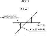
- wall temperature correction 36 multiplies a difference (TA-TLSI) between the corrected output (TLSI) of the circuit temperature sensor 19 and the corrected output (TA) of the intake air temperature sensor 3 by an optimum constant (K1) 42 different for each of flow rates. Furthermore, a wall temperature correction amount ( ⁇ Y) is obtained by multiplying K1 by a gain (K2) 41 corresponding to TA-TLSI and added to a zero span adjusted flow rate signal (QA) of the output of the temperature difference bridge 2.
- K1 a gain
- QA zero span adjusted flow rate signal
- the correction according to the corrected output (TLSI) of the circuit temperature sensor 19 is performed using data of an output correction map 37 so as to correct a flow rate signal (QA1) after correction of the wall temperature, and adjusts the flow rate signal to the target value.
- the corrected output (TA) of the intake air temperature sensor 3 is output as a temperature signal.
- this correction can be compatible not only with correction by a map but also with correction by polynomial.
- the merit of performing correction by polynomial is that it is sufficient to prepare a small capacity for the storage circuit 21 and the ROM 29. With small capacity, it is possible to reduce the chip size and the cost.
- the merit of performing correction by a map is its capability of coping with a sharp change of the correction amount with respect to the input and its capability of achieving high accuracy.
- FIG. 3 illustrates a characteristic diagram of the correction amount ⁇ Y output from the wall temperature correction 36.
- ⁇ Y indicates zero until an absolute value (
- FIG. 4 illustrates a characteristic diagram of the gain (K2) 41.
- the diagram illustrates a characteristic of a step response of zero (0) and one with the threshold as a boundary.
- This threshold can be arbitrarily set, and is desirably set in consideration of the degree of deterioration by aging and characteristic variation in the circuit temperature sensor and the intake air temperature sensor.
- the present embodiment is applied to a case of a circuit configuration described in the first exemplary embodiment having a different correction characteristic, implemented in the wall temperature correction 36.
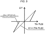
- FIG. 5 illustrates a characteristic diagram of the correction amount ⁇ Y output from the wall temperature correction 36.
- ⁇ Y indicates zero until an absolute value (
- FIG. 6 illustrates a characteristic diagram of the gain (K2) 41.
- the gain is zero until threshold, and illustrates a primary characteristic on and after the threshold.
- This configuration has an advantage of suppressing characteristic variation at discontinuous points before and after the threshold.
- the present embodiment is applied to a case of a circuit configuration described in the first exemplary embodiment having a different correction characteristic, implemented in the wall temperature correction 36.
- FIG. 7 illustrates a characteristic diagram of the correction amount ⁇ Y output from the wall temperature correction 36.
- ⁇ Y indicates a secondary characteristic until the absolute value (
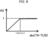
- FIG. 8 illustrates a characteristic diagram of the gain (K2) 41.
- This configuration has an advantage of suppressing characteristic variation before/after the threshold and achieving the primary characteristic with the gradient K1 on and after the threshold.
- the present embodiment is applied to a case of a circuit configuration according to the first exemplary embodiment having a different correction characteristic, implemented in the wall temperature correction 36.
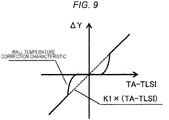
- FIG. 9 illustrates a characteristic diagram of the correction amount ⁇ Y output from the wall temperature correction 36.
- ⁇ Y indicates zero until the absolute value (
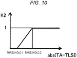
- FIG. 10 illustrates a characteristic diagram of the gain (K2) 41.
- This configuration has an advantage of suppressing characteristic variation before/after the threshold 1 and threshold 2 and achieving the primary characteristic with the gradient K1 on and after the threshold 2.
- the present invention is not limited to the above-described exemplary embodiments, but may include various types of modification.
- the above-described exemplary embodiments give detailed explanation just to allow the present invention to be clearly understood. Therefore, the present invention is not limited to the case having all of components in the configuration.
- a portion of configuration of an exemplary embodiment can be replaced with a portion of configuration of another exemplary embodiment.
- a portion or the configuration of another exemplary embodiment can be added to a certain exemplary embodiment.
- the portions of the configuration of each of the exemplary embodiments addition, deletion, and replacement from another configuration would be possible.
- the above configurations, functions, processing units, processing means, or the like may be implemented by hardware by designing a portion or all with an integrated circuit, for example.
- each of the above-described configurations, functions, or the like may be implemented with software by a processor by interpreting and executing a program designed to realize individual functions.
- Information such as programs, maps, correction values that realize individual functions can be stored in a storage apparatus such as a memory, a ROM, an EPROM, and a flash memory.
Landscapes
- Physics & Mathematics (AREA)
- Fluid Mechanics (AREA)
- General Physics & Mathematics (AREA)
- Measuring Volume Flow (AREA)
- Details Of Flowmeters (AREA)
Claims (6)
- Luftdurchflussmesser, der eine Arithmetikschaltung (22) enthält, die einen Ausgang korrigiert, wobei die Arithmetikschaltung (22) eine Lufttemperatur und eine Sensormodultemperatur als Einstellfaktoren für eine Ausgangskennlinie des Luftdurchflussmessers enthält und
die Ausgangskennlinie in Übereinstimmung mit einer Temperaturdifferenz zwischen der Lufttemperatur und der Sensormodultemperatur korrigiert wird;
dadurch gekennzeichnet, dass
ein Korrekturbetrag (ΔY) im Vergleich zu einem Korrekturbetrag (ΔY), der durch eine primäre Kennlinie angegeben wird, erniedrigt wird, wenn ein Absolutwert der Differenz zwischen der Lufttemperatur und der Sensormodultemperatur kleiner als ein Schwellenwert ist. - Luftdurchflussmesser nach Anspruch 1,
wobei der Korrekturbetrag (ΔY) der Ausgangskennlinie einen ersten Bereich und einen zweiten Bereich mit unterschiedlichen Änderungsraten des Korrekturbetrags (ΔY) enthält. - Luftdurchflussmesser nach Anspruch 2,
wobei der erste Bereich eine Änderungsrate des Korrekturbetrags (ΔY) besitzt, die kleiner als eine Änderungsrate des zweiten Bereichs ist. - Luftdurchflussmesser nach Anspruch 2 oder 3,
wobei die Änderungsrate des Korrekturbetrags (ΔY) in Bezug auf die Temperaturdifferenz zwischen der Lufttemperatur und der Sensormodultemperatur in dem ersten Bereich gleich null ist, und
die Änderungsrate in dem zweiten Bereich die primäre Kennlinie besitzt. - Luftdurchflussmesser nach Anspruch 2 oder 3,
wobei die Änderungsrate des Korrekturbetrags (ΔY) in Bezug auf die Temperaturdifferenz zwischen der Lufttemperatur und der Sensormodultemperatur eine sekundäre Kennlinie in dem ersten Bereich angibt und
die Änderungsrate in dem zweiten Bereich die primäre Kennlinie besitzt. - Luftdurchflussmesser nach Anspruch 2 oder 3,
wobei die Änderungsrate des Korrekturbetrags (ΔY) in Bezug auf die Temperaturdifferenz zwischen der Lufttemperatur und der Sensormodultemperatur in dem ersten Bereich gleich null ist, bis der Absolutwert der Differenz zwischen der Lufttemperatur und der Sensormodultemperatur einen ersten Schwellenwert erreicht, und
die Änderungsrate in dem zweiten Bereich eine sekundäre Kenntinie besitzt, bis der Absolutwert der Differenz zwischen der Lufttemperatur und der Sensormodultemperatur einen zweiten Schwellenwert erreicht.
Applications Claiming Priority (2)
| Application Number | Priority Date | Filing Date | Title |
|---|---|---|---|
| JP2015169972 | 2015-08-31 | ||
| PCT/JP2016/071944 WO2017038312A1 (ja) | 2015-08-31 | 2016-07-27 | 空気流量計 |
Publications (3)
| Publication Number | Publication Date |
|---|---|
| EP3346240A1 EP3346240A1 (de) | 2018-07-11 |
| EP3346240A4 EP3346240A4 (de) | 2019-04-17 |
| EP3346240B1 true EP3346240B1 (de) | 2020-06-24 |
Family
ID=58187236
Family Applications (1)
| Application Number | Title | Priority Date | Filing Date |
|---|---|---|---|
| EP16841344.1A Active EP3346240B1 (de) | 2015-08-31 | 2016-07-27 | Luftdurchflussmesser |
Country Status (5)
| Country | Link |
|---|---|
| US (1) | US10591332B2 (de) |
| EP (1) | EP3346240B1 (de) |
| JP (1) | JP6549235B2 (de) |
| CN (1) | CN107923780B (de) |
| WO (1) | WO2017038312A1 (de) |
Families Citing this family (1)
| Publication number | Priority date | Publication date | Assignee | Title |
|---|---|---|---|---|
| JP6843014B2 (ja) * | 2017-07-31 | 2021-03-17 | アズビル株式会社 | 熱式流量計および流量補正方法 |
Family Cites Families (12)
| Publication number | Priority date | Publication date | Assignee | Title |
|---|---|---|---|---|
| JPS6218708U (de) | 1985-07-19 | 1987-02-04 | ||
| JP2786668B2 (ja) | 1989-04-21 | 1998-08-13 | 株式会社日立製作所 | 自動車のエンジン制御用センサ |
| JPH0814978A (ja) * | 1994-07-05 | 1996-01-19 | Hitachi Ltd | 熱式空気流量計 |
| EP0890827A1 (de) * | 1997-07-08 | 1999-01-13 | Hitachi, Ltd. | Thermische Vorrichtung zum Messen der Strömung und Temperaturfehlerkorrekturgerät dafür |
| DE01918944T1 (de) * | 2000-03-23 | 2004-10-21 | Invensys Systems, Inc., Foxboro | Korrektur für eine zweiphasenströmung in einem digitalen durchflussmesser |
| JP2002054964A (ja) * | 2000-08-10 | 2002-02-20 | Mitsui Mining & Smelting Co Ltd | 流量測定方法及び流量計 |
| CN1249406C (zh) * | 2000-09-04 | 2006-04-05 | 株式会社日立制作所 | 热式空气流量计 |
| CA2647242C (en) * | 2006-05-08 | 2015-08-11 | Invensys Systems, Inc. | Single and multiphase fluid measurements |
| JP2010216906A (ja) * | 2009-03-16 | 2010-09-30 | Hitachi Automotive Systems Ltd | 自動車用流量計 |
| JP5315304B2 (ja) * | 2010-07-30 | 2013-10-16 | 日立オートモティブシステムズ株式会社 | 熱式流量計 |
| JP5271997B2 (ja) * | 2010-12-28 | 2013-08-21 | 日立オートモティブシステムズ株式会社 | 吸気温度センサ |
| JP5914388B2 (ja) | 2013-03-05 | 2016-05-11 | 日立オートモティブシステムズ株式会社 | 熱式流体計測装置 |
-
2016
- 2016-07-27 JP JP2017537655A patent/JP6549235B2/ja active Active
- 2016-07-27 CN CN201680049796.7A patent/CN107923780B/zh active Active
- 2016-07-27 US US15/754,477 patent/US10591332B2/en active Active
- 2016-07-27 WO PCT/JP2016/071944 patent/WO2017038312A1/ja not_active Ceased
- 2016-07-27 EP EP16841344.1A patent/EP3346240B1/de active Active
Non-Patent Citations (1)
| Title |
|---|
| None * |
Also Published As
| Publication number | Publication date |
|---|---|
| EP3346240A1 (de) | 2018-07-11 |
| CN107923780B (zh) | 2021-06-18 |
| CN107923780A (zh) | 2018-04-17 |
| US20180252565A1 (en) | 2018-09-06 |
| WO2017038312A1 (ja) | 2017-03-09 |
| JP6549235B2 (ja) | 2019-07-24 |
| US10591332B2 (en) | 2020-03-17 |
| JPWO2017038312A1 (ja) | 2018-03-22 |
| EP3346240A4 (de) | 2019-04-17 |
Similar Documents
| Publication | Publication Date | Title |
|---|---|---|
| EP2924405B1 (de) | Zulufttemperatursensor und durchströmungsmessvorrichtung | |
| ES2705433T3 (es) | Método para la compensación de deriva de temperatura de dispositivo de medición de temperatura que usa termopar | |
| WO2011125339A1 (en) | Mass flow controller with enhanced operating range | |
| JP5900536B2 (ja) | センサ信号検出装置 | |
| EP2916111B1 (de) | Wärmedurchflussmesser | |
| EP2966419B1 (de) | Heissflüssigkeitsmessvorrichtung | |
| WO2011125338A1 (en) | Method and mass flow controller for enhanced operating range | |
| EP3239675A1 (de) | Vorrichtung zur korrektur eines temperaturmesssignals | |
| US8388224B2 (en) | Engine turbine temperature measurement | |
| US8844348B2 (en) | Gas flow rate measurement device | |
| CN103206312B (zh) | 用于求得传感器的状态的方法和装置 | |
| US9207109B2 (en) | Flow sensor with improved linear output | |
| EP3346240B1 (de) | Luftdurchflussmesser | |
| CN108351261A (zh) | 异常温度检测电路 | |
| US8485725B2 (en) | System and method for detecting an unexpected medium or a change of medium sensed by a thermistor | |
| JP5814884B2 (ja) | 熱式流量測定装置及びこれを用いた制御装置 | |
| JP2010216906A (ja) | 自動車用流量計 | |
| JP2005003596A (ja) | 抵抗測定装置、抵抗測定用集積回路及び抵抗測定方法 | |
| US11391632B2 (en) | Temperature sensor circuit | |
| US10753300B2 (en) | Flow rate detector | |
| US20240159601A1 (en) | Mass flow sensor having an airfoil | |
| WO2020080189A1 (ja) | 流量測定装置及び、流量測定装置の制御方法 | |
| KR20140103615A (ko) | 온도 측정 방법 | |
| JP2025062836A (ja) | 温度測定装置 |
Legal Events
| Date | Code | Title | Description |
|---|---|---|---|
| STAA | Information on the status of an ep patent application or granted ep patent |
Free format text: STATUS: THE INTERNATIONAL PUBLICATION HAS BEEN MADE |
|
| PUAI | Public reference made under article 153(3) epc to a published international application that has entered the european phase |
Free format text: ORIGINAL CODE: 0009012 |
|
| STAA | Information on the status of an ep patent application or granted ep patent |
Free format text: STATUS: REQUEST FOR EXAMINATION WAS MADE |
|
| 17P | Request for examination filed |
Effective date: 20180403 |
|
| AK | Designated contracting states |
Kind code of ref document: A1 Designated state(s): AL AT BE BG CH CY CZ DE DK EE ES FI FR GB GR HR HU IE IS IT LI LT LU LV MC MK MT NL NO PL PT RO RS SE SI SK SM TR |
|
| AX | Request for extension of the european patent |
Extension state: BA ME |
|
| DAV | Request for validation of the european patent (deleted) | ||
| DAX | Request for extension of the european patent (deleted) | ||
| A4 | Supplementary search report drawn up and despatched |
Effective date: 20190320 |
|
| RIC1 | Information provided on ipc code assigned before grant |
Ipc: G01F 15/04 20060101ALI20190314BHEP Ipc: G01F 1/00 20060101ALI20190314BHEP Ipc: G01F 1/696 20060101AFI20190314BHEP Ipc: G01F 1/698 20060101ALI20190314BHEP Ipc: G01F 1/68 20060101ALI20190314BHEP |
|
| GRAP | Despatch of communication of intention to grant a patent |
Free format text: ORIGINAL CODE: EPIDOSNIGR1 |
|
| STAA | Information on the status of an ep patent application or granted ep patent |
Free format text: STATUS: GRANT OF PATENT IS INTENDED |
|
| INTG | Intention to grant announced |
Effective date: 20200204 |
|
| GRAS | Grant fee paid |
Free format text: ORIGINAL CODE: EPIDOSNIGR3 |
|
| GRAA | (expected) grant |
Free format text: ORIGINAL CODE: 0009210 |
|
| STAA | Information on the status of an ep patent application or granted ep patent |
Free format text: STATUS: THE PATENT HAS BEEN GRANTED |
|
| AK | Designated contracting states |
Kind code of ref document: B1 Designated state(s): AL AT BE BG CH CY CZ DE DK EE ES FI FR GB GR HR HU IE IS IT LI LT LU LV MC MK MT NL NO PL PT RO RS SE SI SK SM TR |
|
| REG | Reference to a national code |
Ref country code: GB Ref legal event code: FG4D |
|
| REG | Reference to a national code |
Ref country code: CH Ref legal event code: EP |
|
| REG | Reference to a national code |
Ref country code: AT Ref legal event code: REF Ref document number: 1284347 Country of ref document: AT Kind code of ref document: T Effective date: 20200715 |
|
| REG | Reference to a national code |
Ref country code: DE Ref legal event code: R096 Ref document number: 602016038883 Country of ref document: DE |
|
| REG | Reference to a national code |
Ref country code: IE Ref legal event code: FG4D |
|
| PG25 | Lapsed in a contracting state [announced via postgrant information from national office to epo] |
Ref country code: GR Free format text: LAPSE BECAUSE OF FAILURE TO SUBMIT A TRANSLATION OF THE DESCRIPTION OR TO PAY THE FEE WITHIN THE PRESCRIBED TIME-LIMIT Effective date: 20200925 Ref country code: NO Free format text: LAPSE BECAUSE OF FAILURE TO SUBMIT A TRANSLATION OF THE DESCRIPTION OR TO PAY THE FEE WITHIN THE PRESCRIBED TIME-LIMIT Effective date: 20200924 Ref country code: FI Free format text: LAPSE BECAUSE OF FAILURE TO SUBMIT A TRANSLATION OF THE DESCRIPTION OR TO PAY THE FEE WITHIN THE PRESCRIBED TIME-LIMIT Effective date: 20200624 Ref country code: SE Free format text: LAPSE BECAUSE OF FAILURE TO SUBMIT A TRANSLATION OF THE DESCRIPTION OR TO PAY THE FEE WITHIN THE PRESCRIBED TIME-LIMIT Effective date: 20200624 Ref country code: LT Free format text: LAPSE BECAUSE OF FAILURE TO SUBMIT A TRANSLATION OF THE DESCRIPTION OR TO PAY THE FEE WITHIN THE PRESCRIBED TIME-LIMIT Effective date: 20200624 |
|
| REG | Reference to a national code |
Ref country code: LT Ref legal event code: MG4D |
|
| PG25 | Lapsed in a contracting state [announced via postgrant information from national office to epo] |
Ref country code: BG Free format text: LAPSE BECAUSE OF FAILURE TO SUBMIT A TRANSLATION OF THE DESCRIPTION OR TO PAY THE FEE WITHIN THE PRESCRIBED TIME-LIMIT Effective date: 20200924 Ref country code: RS Free format text: LAPSE BECAUSE OF FAILURE TO SUBMIT A TRANSLATION OF THE DESCRIPTION OR TO PAY THE FEE WITHIN THE PRESCRIBED TIME-LIMIT Effective date: 20200624 Ref country code: LV Free format text: LAPSE BECAUSE OF FAILURE TO SUBMIT A TRANSLATION OF THE DESCRIPTION OR TO PAY THE FEE WITHIN THE PRESCRIBED TIME-LIMIT Effective date: 20200624 Ref country code: HR Free format text: LAPSE BECAUSE OF FAILURE TO SUBMIT A TRANSLATION OF THE DESCRIPTION OR TO PAY THE FEE WITHIN THE PRESCRIBED TIME-LIMIT Effective date: 20200624 |
|
| REG | Reference to a national code |
Ref country code: NL Ref legal event code: MP Effective date: 20200624 |
|
| REG | Reference to a national code |
Ref country code: AT Ref legal event code: MK05 Ref document number: 1284347 Country of ref document: AT Kind code of ref document: T Effective date: 20200624 |
|
| PG25 | Lapsed in a contracting state [announced via postgrant information from national office to epo] |
Ref country code: NL Free format text: LAPSE BECAUSE OF FAILURE TO SUBMIT A TRANSLATION OF THE DESCRIPTION OR TO PAY THE FEE WITHIN THE PRESCRIBED TIME-LIMIT Effective date: 20200624 Ref country code: AL Free format text: LAPSE BECAUSE OF FAILURE TO SUBMIT A TRANSLATION OF THE DESCRIPTION OR TO PAY THE FEE WITHIN THE PRESCRIBED TIME-LIMIT Effective date: 20200624 |
|
| PG25 | Lapsed in a contracting state [announced via postgrant information from national office to epo] |
Ref country code: AT Free format text: LAPSE BECAUSE OF FAILURE TO SUBMIT A TRANSLATION OF THE DESCRIPTION OR TO PAY THE FEE WITHIN THE PRESCRIBED TIME-LIMIT Effective date: 20200624 Ref country code: SM Free format text: LAPSE BECAUSE OF FAILURE TO SUBMIT A TRANSLATION OF THE DESCRIPTION OR TO PAY THE FEE WITHIN THE PRESCRIBED TIME-LIMIT Effective date: 20200624 Ref country code: EE Free format text: LAPSE BECAUSE OF FAILURE TO SUBMIT A TRANSLATION OF THE DESCRIPTION OR TO PAY THE FEE WITHIN THE PRESCRIBED TIME-LIMIT Effective date: 20200624 Ref country code: CZ Free format text: LAPSE BECAUSE OF FAILURE TO SUBMIT A TRANSLATION OF THE DESCRIPTION OR TO PAY THE FEE WITHIN THE PRESCRIBED TIME-LIMIT Effective date: 20200624 Ref country code: RO Free format text: LAPSE BECAUSE OF FAILURE TO SUBMIT A TRANSLATION OF THE DESCRIPTION OR TO PAY THE FEE WITHIN THE PRESCRIBED TIME-LIMIT Effective date: 20200624 Ref country code: IT Free format text: LAPSE BECAUSE OF FAILURE TO SUBMIT A TRANSLATION OF THE DESCRIPTION OR TO PAY THE FEE WITHIN THE PRESCRIBED TIME-LIMIT Effective date: 20200624 Ref country code: ES Free format text: LAPSE BECAUSE OF FAILURE TO SUBMIT A TRANSLATION OF THE DESCRIPTION OR TO PAY THE FEE WITHIN THE PRESCRIBED TIME-LIMIT Effective date: 20200624 Ref country code: PT Free format text: LAPSE BECAUSE OF FAILURE TO SUBMIT A TRANSLATION OF THE DESCRIPTION OR TO PAY THE FEE WITHIN THE PRESCRIBED TIME-LIMIT Effective date: 20201026 |
|
| PG25 | Lapsed in a contracting state [announced via postgrant information from national office to epo] |
Ref country code: PL Free format text: LAPSE BECAUSE OF FAILURE TO SUBMIT A TRANSLATION OF THE DESCRIPTION OR TO PAY THE FEE WITHIN THE PRESCRIBED TIME-LIMIT Effective date: 20200624 Ref country code: SK Free format text: LAPSE BECAUSE OF FAILURE TO SUBMIT A TRANSLATION OF THE DESCRIPTION OR TO PAY THE FEE WITHIN THE PRESCRIBED TIME-LIMIT Effective date: 20200624 Ref country code: IS Free format text: LAPSE BECAUSE OF FAILURE TO SUBMIT A TRANSLATION OF THE DESCRIPTION OR TO PAY THE FEE WITHIN THE PRESCRIBED TIME-LIMIT Effective date: 20201024 |
|
| REG | Reference to a national code |
Ref country code: CH Ref legal event code: PL |
|
| REG | Reference to a national code |
Ref country code: DE Ref legal event code: R082 Ref document number: 602016038883 Country of ref document: DE Representative=s name: MERH-IP MATIAS ERNY REICHL HOFFMANN PATENTANWA, DE Ref country code: DE Ref legal event code: R081 Ref document number: 602016038883 Country of ref document: DE Owner name: HITACHI ASTEMO, LTD., HITACHINAKA-SHI, JP Free format text: FORMER OWNER: HITACHI AUTOMOTIVE SYSTEMS, LTD., HITACHINAKA-SHI, IBARAKI, JP |
|
| REG | Reference to a national code |
Ref country code: DE Ref legal event code: R097 Ref document number: 602016038883 Country of ref document: DE |
|
| PG25 | Lapsed in a contracting state [announced via postgrant information from national office to epo] |
Ref country code: MC Free format text: LAPSE BECAUSE OF FAILURE TO SUBMIT A TRANSLATION OF THE DESCRIPTION OR TO PAY THE FEE WITHIN THE PRESCRIBED TIME-LIMIT Effective date: 20200624 |
|
| REG | Reference to a national code |
Ref country code: BE Ref legal event code: MM Effective date: 20200731 |
|
| PG25 | Lapsed in a contracting state [announced via postgrant information from national office to epo] |
Ref country code: LU Free format text: LAPSE BECAUSE OF NON-PAYMENT OF DUE FEES Effective date: 20200727 Ref country code: LI Free format text: LAPSE BECAUSE OF NON-PAYMENT OF DUE FEES Effective date: 20200731 Ref country code: DK Free format text: LAPSE BECAUSE OF FAILURE TO SUBMIT A TRANSLATION OF THE DESCRIPTION OR TO PAY THE FEE WITHIN THE PRESCRIBED TIME-LIMIT Effective date: 20200624 Ref country code: CH Free format text: LAPSE BECAUSE OF NON-PAYMENT OF DUE FEES Effective date: 20200731 |
|
| PLBE | No opposition filed within time limit |
Free format text: ORIGINAL CODE: 0009261 |
|
| STAA | Information on the status of an ep patent application or granted ep patent |
Free format text: STATUS: NO OPPOSITION FILED WITHIN TIME LIMIT |
|
| GBPC | Gb: european patent ceased through non-payment of renewal fee |
Effective date: 20200924 |
|
| PG25 | Lapsed in a contracting state [announced via postgrant information from national office to epo] |
Ref country code: BE Free format text: LAPSE BECAUSE OF NON-PAYMENT OF DUE FEES Effective date: 20200731 |
|
| 26N | No opposition filed |
Effective date: 20210325 |
|
| PG25 | Lapsed in a contracting state [announced via postgrant information from national office to epo] |
Ref country code: FR Free format text: LAPSE BECAUSE OF NON-PAYMENT OF DUE FEES Effective date: 20200824 |
|
| PG25 | Lapsed in a contracting state [announced via postgrant information from national office to epo] |
Ref country code: SI Free format text: LAPSE BECAUSE OF FAILURE TO SUBMIT A TRANSLATION OF THE DESCRIPTION OR TO PAY THE FEE WITHIN THE PRESCRIBED TIME-LIMIT Effective date: 20200624 Ref country code: GB Free format text: LAPSE BECAUSE OF NON-PAYMENT OF DUE FEES Effective date: 20200924 Ref country code: IE Free format text: LAPSE BECAUSE OF NON-PAYMENT OF DUE FEES Effective date: 20200727 |
|
| PG25 | Lapsed in a contracting state [announced via postgrant information from national office to epo] |
Ref country code: TR Free format text: LAPSE BECAUSE OF FAILURE TO SUBMIT A TRANSLATION OF THE DESCRIPTION OR TO PAY THE FEE WITHIN THE PRESCRIBED TIME-LIMIT Effective date: 20200624 Ref country code: MT Free format text: LAPSE BECAUSE OF FAILURE TO SUBMIT A TRANSLATION OF THE DESCRIPTION OR TO PAY THE FEE WITHIN THE PRESCRIBED TIME-LIMIT Effective date: 20200624 Ref country code: CY Free format text: LAPSE BECAUSE OF FAILURE TO SUBMIT A TRANSLATION OF THE DESCRIPTION OR TO PAY THE FEE WITHIN THE PRESCRIBED TIME-LIMIT Effective date: 20200624 |
|
| PG25 | Lapsed in a contracting state [announced via postgrant information from national office to epo] |
Ref country code: MK Free format text: LAPSE BECAUSE OF FAILURE TO SUBMIT A TRANSLATION OF THE DESCRIPTION OR TO PAY THE FEE WITHIN THE PRESCRIBED TIME-LIMIT Effective date: 20200624 |
|
| PGFP | Annual fee paid to national office [announced via postgrant information from national office to epo] |
Ref country code: DE Payment date: 20250604 Year of fee payment: 10 |