EP3345630A1 - Polymer für einen gelenkspacer, implantate und/oder als sehnen- oder bänderersatz - Google Patents
Polymer für einen gelenkspacer, implantate und/oder als sehnen- oder bänderersatz Download PDFInfo
- Publication number
- EP3345630A1 EP3345630A1 EP18153478.5A EP18153478A EP3345630A1 EP 3345630 A1 EP3345630 A1 EP 3345630A1 EP 18153478 A EP18153478 A EP 18153478A EP 3345630 A1 EP3345630 A1 EP 3345630A1
- Authority
- EP
- European Patent Office
- Prior art keywords
- spacer
- polymer
- partially
- gelenkspacer
- edge
- Prior art date
- Legal status (The legal status is an assumption and is not a legal conclusion. Google has not performed a legal analysis and makes no representation as to the accuracy of the status listed.)
- Granted
Links
Images









Classifications
-
- A—HUMAN NECESSITIES
- A61—MEDICAL OR VETERINARY SCIENCE; HYGIENE
- A61F—FILTERS IMPLANTABLE INTO BLOOD VESSELS; PROSTHESES; DEVICES PROVIDING PATENCY TO, OR PREVENTING COLLAPSING OF, TUBULAR STRUCTURES OF THE BODY, e.g. STENTS; ORTHOPAEDIC, NURSING OR CONTRACEPTIVE DEVICES; FOMENTATION; TREATMENT OR PROTECTION OF EYES OR EARS; BANDAGES, DRESSINGS OR ABSORBENT PADS; FIRST-AID KITS
- A61F2/00—Filters implantable into blood vessels; Prostheses, i.e. artificial substitutes or replacements for parts of the body; Appliances for connecting them with the body; Devices providing patency to, or preventing collapsing of, tubular structures of the body, e.g. stents
- A61F2/02—Prostheses implantable into the body
- A61F2/30—Joints
- A61F2/38—Joints for elbows or knees
- A61F2/3872—Meniscus for implantation between the natural bone surfaces
-
- A—HUMAN NECESSITIES
- A61—MEDICAL OR VETERINARY SCIENCE; HYGIENE
- A61F—FILTERS IMPLANTABLE INTO BLOOD VESSELS; PROSTHESES; DEVICES PROVIDING PATENCY TO, OR PREVENTING COLLAPSING OF, TUBULAR STRUCTURES OF THE BODY, e.g. STENTS; ORTHOPAEDIC, NURSING OR CONTRACEPTIVE DEVICES; FOMENTATION; TREATMENT OR PROTECTION OF EYES OR EARS; BANDAGES, DRESSINGS OR ABSORBENT PADS; FIRST-AID KITS
- A61F2/00—Filters implantable into blood vessels; Prostheses, i.e. artificial substitutes or replacements for parts of the body; Appliances for connecting them with the body; Devices providing patency to, or preventing collapsing of, tubular structures of the body, e.g. stents
- A61F2/02—Prostheses implantable into the body
- A61F2/30—Joints
-
- A—HUMAN NECESSITIES
- A61—MEDICAL OR VETERINARY SCIENCE; HYGIENE
- A61F—FILTERS IMPLANTABLE INTO BLOOD VESSELS; PROSTHESES; DEVICES PROVIDING PATENCY TO, OR PREVENTING COLLAPSING OF, TUBULAR STRUCTURES OF THE BODY, e.g. STENTS; ORTHOPAEDIC, NURSING OR CONTRACEPTIVE DEVICES; FOMENTATION; TREATMENT OR PROTECTION OF EYES OR EARS; BANDAGES, DRESSINGS OR ABSORBENT PADS; FIRST-AID KITS
- A61F2/00—Filters implantable into blood vessels; Prostheses, i.e. artificial substitutes or replacements for parts of the body; Appliances for connecting them with the body; Devices providing patency to, or preventing collapsing of, tubular structures of the body, e.g. stents
- A61F2/02—Prostheses implantable into the body
- A61F2/30—Joints
- A61F2/30756—Cartilage endoprostheses
-
- A—HUMAN NECESSITIES
- A61—MEDICAL OR VETERINARY SCIENCE; HYGIENE
- A61F—FILTERS IMPLANTABLE INTO BLOOD VESSELS; PROSTHESES; DEVICES PROVIDING PATENCY TO, OR PREVENTING COLLAPSING OF, TUBULAR STRUCTURES OF THE BODY, e.g. STENTS; ORTHOPAEDIC, NURSING OR CONTRACEPTIVE DEVICES; FOMENTATION; TREATMENT OR PROTECTION OF EYES OR EARS; BANDAGES, DRESSINGS OR ABSORBENT PADS; FIRST-AID KITS
- A61F2/00—Filters implantable into blood vessels; Prostheses, i.e. artificial substitutes or replacements for parts of the body; Appliances for connecting them with the body; Devices providing patency to, or preventing collapsing of, tubular structures of the body, e.g. stents
- A61F2/02—Prostheses implantable into the body
- A61F2/30—Joints
- A61F2/32—Joints for the hip
-
- A—HUMAN NECESSITIES
- A61—MEDICAL OR VETERINARY SCIENCE; HYGIENE
- A61F—FILTERS IMPLANTABLE INTO BLOOD VESSELS; PROSTHESES; DEVICES PROVIDING PATENCY TO, OR PREVENTING COLLAPSING OF, TUBULAR STRUCTURES OF THE BODY, e.g. STENTS; ORTHOPAEDIC, NURSING OR CONTRACEPTIVE DEVICES; FOMENTATION; TREATMENT OR PROTECTION OF EYES OR EARS; BANDAGES, DRESSINGS OR ABSORBENT PADS; FIRST-AID KITS
- A61F2/00—Filters implantable into blood vessels; Prostheses, i.e. artificial substitutes or replacements for parts of the body; Appliances for connecting them with the body; Devices providing patency to, or preventing collapsing of, tubular structures of the body, e.g. stents
- A61F2/02—Prostheses implantable into the body
- A61F2/30—Joints
- A61F2/38—Joints for elbows or knees
- A61F2/3836—Special connection between upper and lower leg, e.g. constrained
-
- A—HUMAN NECESSITIES
- A61—MEDICAL OR VETERINARY SCIENCE; HYGIENE
- A61F—FILTERS IMPLANTABLE INTO BLOOD VESSELS; PROSTHESES; DEVICES PROVIDING PATENCY TO, OR PREVENTING COLLAPSING OF, TUBULAR STRUCTURES OF THE BODY, e.g. STENTS; ORTHOPAEDIC, NURSING OR CONTRACEPTIVE DEVICES; FOMENTATION; TREATMENT OR PROTECTION OF EYES OR EARS; BANDAGES, DRESSINGS OR ABSORBENT PADS; FIRST-AID KITS
- A61F2/00—Filters implantable into blood vessels; Prostheses, i.e. artificial substitutes or replacements for parts of the body; Appliances for connecting them with the body; Devices providing patency to, or preventing collapsing of, tubular structures of the body, e.g. stents
- A61F2/02—Prostheses implantable into the body
- A61F2/30—Joints
- A61F2/38—Joints for elbows or knees
- A61F2/3877—Patellae or trochleae
-
- A—HUMAN NECESSITIES
- A61—MEDICAL OR VETERINARY SCIENCE; HYGIENE
- A61L—METHODS OR APPARATUS FOR STERILISING MATERIALS OR OBJECTS IN GENERAL; DISINFECTION, STERILISATION OR DEODORISATION OF AIR; CHEMICAL ASPECTS OF BANDAGES, DRESSINGS, ABSORBENT PADS OR SURGICAL ARTICLES; MATERIALS FOR BANDAGES, DRESSINGS, ABSORBENT PADS OR SURGICAL ARTICLES
- A61L27/00—Materials for grafts or prostheses or for coating grafts or prostheses
- A61L27/14—Macromolecular materials
- A61L27/16—Macromolecular materials obtained by reactions only involving carbon-to-carbon unsaturated bonds
- A61L27/165—Rubbers
-
- A—HUMAN NECESSITIES
- A61—MEDICAL OR VETERINARY SCIENCE; HYGIENE
- A61L—METHODS OR APPARATUS FOR STERILISING MATERIALS OR OBJECTS IN GENERAL; DISINFECTION, STERILISATION OR DEODORISATION OF AIR; CHEMICAL ASPECTS OF BANDAGES, DRESSINGS, ABSORBENT PADS OR SURGICAL ARTICLES; MATERIALS FOR BANDAGES, DRESSINGS, ABSORBENT PADS OR SURGICAL ARTICLES
- A61L27/00—Materials for grafts or prostheses or for coating grafts or prostheses
- A61L27/14—Macromolecular materials
- A61L27/18—Macromolecular materials obtained otherwise than by reactions only involving carbon-to-carbon unsaturated bonds
-
- A—HUMAN NECESSITIES
- A61—MEDICAL OR VETERINARY SCIENCE; HYGIENE
- A61L—METHODS OR APPARATUS FOR STERILISING MATERIALS OR OBJECTS IN GENERAL; DISINFECTION, STERILISATION OR DEODORISATION OF AIR; CHEMICAL ASPECTS OF BANDAGES, DRESSINGS, ABSORBENT PADS OR SURGICAL ARTICLES; MATERIALS FOR BANDAGES, DRESSINGS, ABSORBENT PADS OR SURGICAL ARTICLES
- A61L27/00—Materials for grafts or prostheses or for coating grafts or prostheses
- A61L27/50—Materials characterised by their function or physical properties, e.g. injectable or lubricating compositions, shape-memory materials, surface modified materials
-
- A—HUMAN NECESSITIES
- A61—MEDICAL OR VETERINARY SCIENCE; HYGIENE
- A61L—METHODS OR APPARATUS FOR STERILISING MATERIALS OR OBJECTS IN GENERAL; DISINFECTION, STERILISATION OR DEODORISATION OF AIR; CHEMICAL ASPECTS OF BANDAGES, DRESSINGS, ABSORBENT PADS OR SURGICAL ARTICLES; MATERIALS FOR BANDAGES, DRESSINGS, ABSORBENT PADS OR SURGICAL ARTICLES
- A61L27/00—Materials for grafts or prostheses or for coating grafts or prostheses
- A61L27/50—Materials characterised by their function or physical properties, e.g. injectable or lubricating compositions, shape-memory materials, surface modified materials
- A61L27/56—Porous materials, e.g. foams or sponges
-
- A—HUMAN NECESSITIES
- A61—MEDICAL OR VETERINARY SCIENCE; HYGIENE
- A61F—FILTERS IMPLANTABLE INTO BLOOD VESSELS; PROSTHESES; DEVICES PROVIDING PATENCY TO, OR PREVENTING COLLAPSING OF, TUBULAR STRUCTURES OF THE BODY, e.g. STENTS; ORTHOPAEDIC, NURSING OR CONTRACEPTIVE DEVICES; FOMENTATION; TREATMENT OR PROTECTION OF EYES OR EARS; BANDAGES, DRESSINGS OR ABSORBENT PADS; FIRST-AID KITS
- A61F2/00—Filters implantable into blood vessels; Prostheses, i.e. artificial substitutes or replacements for parts of the body; Appliances for connecting them with the body; Devices providing patency to, or preventing collapsing of, tubular structures of the body, e.g. stents
- A61F2/02—Prostheses implantable into the body
- A61F2/30—Joints
- A61F2/32—Joints for the hip
- A61F2/34—Acetabular cups
-
- A—HUMAN NECESSITIES
- A61—MEDICAL OR VETERINARY SCIENCE; HYGIENE
- A61F—FILTERS IMPLANTABLE INTO BLOOD VESSELS; PROSTHESES; DEVICES PROVIDING PATENCY TO, OR PREVENTING COLLAPSING OF, TUBULAR STRUCTURES OF THE BODY, e.g. STENTS; ORTHOPAEDIC, NURSING OR CONTRACEPTIVE DEVICES; FOMENTATION; TREATMENT OR PROTECTION OF EYES OR EARS; BANDAGES, DRESSINGS OR ABSORBENT PADS; FIRST-AID KITS
- A61F2/00—Filters implantable into blood vessels; Prostheses, i.e. artificial substitutes or replacements for parts of the body; Appliances for connecting them with the body; Devices providing patency to, or preventing collapsing of, tubular structures of the body, e.g. stents
- A61F2/02—Prostheses implantable into the body
- A61F2/30—Joints
- A61F2/32—Joints for the hip
- A61F2/36—Femoral heads ; Femoral endoprostheses
-
- A—HUMAN NECESSITIES
- A61—MEDICAL OR VETERINARY SCIENCE; HYGIENE
- A61F—FILTERS IMPLANTABLE INTO BLOOD VESSELS; PROSTHESES; DEVICES PROVIDING PATENCY TO, OR PREVENTING COLLAPSING OF, TUBULAR STRUCTURES OF THE BODY, e.g. STENTS; ORTHOPAEDIC, NURSING OR CONTRACEPTIVE DEVICES; FOMENTATION; TREATMENT OR PROTECTION OF EYES OR EARS; BANDAGES, DRESSINGS OR ABSORBENT PADS; FIRST-AID KITS
- A61F2/00—Filters implantable into blood vessels; Prostheses, i.e. artificial substitutes or replacements for parts of the body; Appliances for connecting them with the body; Devices providing patency to, or preventing collapsing of, tubular structures of the body, e.g. stents
- A61F2/02—Prostheses implantable into the body
- A61F2/30—Joints
- A61F2002/30001—Additional features of subject-matter classified in A61F2/28, A61F2/30 and subgroups thereof
- A61F2002/30003—Material related properties of the prosthesis or of a coating on the prosthesis
-
- A—HUMAN NECESSITIES
- A61—MEDICAL OR VETERINARY SCIENCE; HYGIENE
- A61F—FILTERS IMPLANTABLE INTO BLOOD VESSELS; PROSTHESES; DEVICES PROVIDING PATENCY TO, OR PREVENTING COLLAPSING OF, TUBULAR STRUCTURES OF THE BODY, e.g. STENTS; ORTHOPAEDIC, NURSING OR CONTRACEPTIVE DEVICES; FOMENTATION; TREATMENT OR PROTECTION OF EYES OR EARS; BANDAGES, DRESSINGS OR ABSORBENT PADS; FIRST-AID KITS
- A61F2/00—Filters implantable into blood vessels; Prostheses, i.e. artificial substitutes or replacements for parts of the body; Appliances for connecting them with the body; Devices providing patency to, or preventing collapsing of, tubular structures of the body, e.g. stents
- A61F2/02—Prostheses implantable into the body
- A61F2/30—Joints
- A61F2002/30001—Additional features of subject-matter classified in A61F2/28, A61F2/30 and subgroups thereof
- A61F2002/30003—Material related properties of the prosthesis or of a coating on the prosthesis
- A61F2002/30004—Material related properties of the prosthesis or of a coating on the prosthesis the prosthesis being made from materials having different values of a given property at different locations within the same prosthesis
- A61F2002/30016—Material related properties of the prosthesis or of a coating on the prosthesis the prosthesis being made from materials having different values of a given property at different locations within the same prosthesis differing in hardness, e.g. Vickers, Shore, Brinell
-
- A—HUMAN NECESSITIES
- A61—MEDICAL OR VETERINARY SCIENCE; HYGIENE
- A61F—FILTERS IMPLANTABLE INTO BLOOD VESSELS; PROSTHESES; DEVICES PROVIDING PATENCY TO, OR PREVENTING COLLAPSING OF, TUBULAR STRUCTURES OF THE BODY, e.g. STENTS; ORTHOPAEDIC, NURSING OR CONTRACEPTIVE DEVICES; FOMENTATION; TREATMENT OR PROTECTION OF EYES OR EARS; BANDAGES, DRESSINGS OR ABSORBENT PADS; FIRST-AID KITS
- A61F2/00—Filters implantable into blood vessels; Prostheses, i.e. artificial substitutes or replacements for parts of the body; Appliances for connecting them with the body; Devices providing patency to, or preventing collapsing of, tubular structures of the body, e.g. stents
- A61F2/02—Prostheses implantable into the body
- A61F2/30—Joints
- A61F2002/30001—Additional features of subject-matter classified in A61F2/28, A61F2/30 and subgroups thereof
- A61F2002/30003—Material related properties of the prosthesis or of a coating on the prosthesis
- A61F2002/3006—Properties of materials and coating materials
- A61F2002/3008—Properties of materials and coating materials radio-opaque, e.g. radio-opaque markers
-
- A—HUMAN NECESSITIES
- A61—MEDICAL OR VETERINARY SCIENCE; HYGIENE
- A61F—FILTERS IMPLANTABLE INTO BLOOD VESSELS; PROSTHESES; DEVICES PROVIDING PATENCY TO, OR PREVENTING COLLAPSING OF, TUBULAR STRUCTURES OF THE BODY, e.g. STENTS; ORTHOPAEDIC, NURSING OR CONTRACEPTIVE DEVICES; FOMENTATION; TREATMENT OR PROTECTION OF EYES OR EARS; BANDAGES, DRESSINGS OR ABSORBENT PADS; FIRST-AID KITS
- A61F2/00—Filters implantable into blood vessels; Prostheses, i.e. artificial substitutes or replacements for parts of the body; Appliances for connecting them with the body; Devices providing patency to, or preventing collapsing of, tubular structures of the body, e.g. stents
- A61F2/02—Prostheses implantable into the body
- A61F2/30—Joints
- A61F2002/30001—Additional features of subject-matter classified in A61F2/28, A61F2/30 and subgroups thereof
- A61F2002/30316—The prosthesis having different structural features at different locations within the same prosthesis; Connections between prosthetic parts; Special structural features of bone or joint prostheses not otherwise provided for
- A61F2002/30329—Connections or couplings between prosthetic parts, e.g. between modular parts; Connecting elements
-
- A—HUMAN NECESSITIES
- A61—MEDICAL OR VETERINARY SCIENCE; HYGIENE
- A61F—FILTERS IMPLANTABLE INTO BLOOD VESSELS; PROSTHESES; DEVICES PROVIDING PATENCY TO, OR PREVENTING COLLAPSING OF, TUBULAR STRUCTURES OF THE BODY, e.g. STENTS; ORTHOPAEDIC, NURSING OR CONTRACEPTIVE DEVICES; FOMENTATION; TREATMENT OR PROTECTION OF EYES OR EARS; BANDAGES, DRESSINGS OR ABSORBENT PADS; FIRST-AID KITS
- A61F2/00—Filters implantable into blood vessels; Prostheses, i.e. artificial substitutes or replacements for parts of the body; Appliances for connecting them with the body; Devices providing patency to, or preventing collapsing of, tubular structures of the body, e.g. stents
- A61F2/02—Prostheses implantable into the body
- A61F2/30—Joints
- A61F2002/30001—Additional features of subject-matter classified in A61F2/28, A61F2/30 and subgroups thereof
- A61F2002/30316—The prosthesis having different structural features at different locations within the same prosthesis; Connections between prosthetic parts; Special structural features of bone or joint prostheses not otherwise provided for
- A61F2002/30329—Connections or couplings between prosthetic parts, e.g. between modular parts; Connecting elements
- A61F2002/30461—Connections or couplings between prosthetic parts, e.g. between modular parts; Connecting elements sutured, ligatured or stitched
-
- A—HUMAN NECESSITIES
- A61—MEDICAL OR VETERINARY SCIENCE; HYGIENE
- A61F—FILTERS IMPLANTABLE INTO BLOOD VESSELS; PROSTHESES; DEVICES PROVIDING PATENCY TO, OR PREVENTING COLLAPSING OF, TUBULAR STRUCTURES OF THE BODY, e.g. STENTS; ORTHOPAEDIC, NURSING OR CONTRACEPTIVE DEVICES; FOMENTATION; TREATMENT OR PROTECTION OF EYES OR EARS; BANDAGES, DRESSINGS OR ABSORBENT PADS; FIRST-AID KITS
- A61F2/00—Filters implantable into blood vessels; Prostheses, i.e. artificial substitutes or replacements for parts of the body; Appliances for connecting them with the body; Devices providing patency to, or preventing collapsing of, tubular structures of the body, e.g. stents
- A61F2/02—Prostheses implantable into the body
- A61F2/30—Joints
- A61F2002/30001—Additional features of subject-matter classified in A61F2/28, A61F2/30 and subgroups thereof
- A61F2002/30316—The prosthesis having different structural features at different locations within the same prosthesis; Connections between prosthetic parts; Special structural features of bone or joint prostheses not otherwise provided for
- A61F2002/30329—Connections or couplings between prosthetic parts, e.g. between modular parts; Connecting elements
- A61F2002/30462—Connections or couplings between prosthetic parts, e.g. between modular parts; Connecting elements retained or tied with a rope, string, thread, wire or cable
-
- A—HUMAN NECESSITIES
- A61—MEDICAL OR VETERINARY SCIENCE; HYGIENE
- A61F—FILTERS IMPLANTABLE INTO BLOOD VESSELS; PROSTHESES; DEVICES PROVIDING PATENCY TO, OR PREVENTING COLLAPSING OF, TUBULAR STRUCTURES OF THE BODY, e.g. STENTS; ORTHOPAEDIC, NURSING OR CONTRACEPTIVE DEVICES; FOMENTATION; TREATMENT OR PROTECTION OF EYES OR EARS; BANDAGES, DRESSINGS OR ABSORBENT PADS; FIRST-AID KITS
- A61F2/00—Filters implantable into blood vessels; Prostheses, i.e. artificial substitutes or replacements for parts of the body; Appliances for connecting them with the body; Devices providing patency to, or preventing collapsing of, tubular structures of the body, e.g. stents
- A61F2/02—Prostheses implantable into the body
- A61F2/30—Joints
- A61F2002/30001—Additional features of subject-matter classified in A61F2/28, A61F2/30 and subgroups thereof
- A61F2002/30316—The prosthesis having different structural features at different locations within the same prosthesis; Connections between prosthetic parts; Special structural features of bone or joint prostheses not otherwise provided for
- A61F2002/30329—Connections or couplings between prosthetic parts, e.g. between modular parts; Connecting elements
- A61F2002/30467—Connections or couplings between prosthetic parts, e.g. between modular parts; Connecting elements using hook and loop-type fasteners
-
- A—HUMAN NECESSITIES
- A61—MEDICAL OR VETERINARY SCIENCE; HYGIENE
- A61F—FILTERS IMPLANTABLE INTO BLOOD VESSELS; PROSTHESES; DEVICES PROVIDING PATENCY TO, OR PREVENTING COLLAPSING OF, TUBULAR STRUCTURES OF THE BODY, e.g. STENTS; ORTHOPAEDIC, NURSING OR CONTRACEPTIVE DEVICES; FOMENTATION; TREATMENT OR PROTECTION OF EYES OR EARS; BANDAGES, DRESSINGS OR ABSORBENT PADS; FIRST-AID KITS
- A61F2/00—Filters implantable into blood vessels; Prostheses, i.e. artificial substitutes or replacements for parts of the body; Appliances for connecting them with the body; Devices providing patency to, or preventing collapsing of, tubular structures of the body, e.g. stents
- A61F2/02—Prostheses implantable into the body
- A61F2/30—Joints
- A61F2002/30001—Additional features of subject-matter classified in A61F2/28, A61F2/30 and subgroups thereof
- A61F2002/30316—The prosthesis having different structural features at different locations within the same prosthesis; Connections between prosthetic parts; Special structural features of bone or joint prostheses not otherwise provided for
- A61F2002/30535—Special structural features of bone or joint prostheses not otherwise provided for
- A61F2002/30576—Special structural features of bone or joint prostheses not otherwise provided for with extending fixation tabs
-
- A—HUMAN NECESSITIES
- A61—MEDICAL OR VETERINARY SCIENCE; HYGIENE
- A61F—FILTERS IMPLANTABLE INTO BLOOD VESSELS; PROSTHESES; DEVICES PROVIDING PATENCY TO, OR PREVENTING COLLAPSING OF, TUBULAR STRUCTURES OF THE BODY, e.g. STENTS; ORTHOPAEDIC, NURSING OR CONTRACEPTIVE DEVICES; FOMENTATION; TREATMENT OR PROTECTION OF EYES OR EARS; BANDAGES, DRESSINGS OR ABSORBENT PADS; FIRST-AID KITS
- A61F2/00—Filters implantable into blood vessels; Prostheses, i.e. artificial substitutes or replacements for parts of the body; Appliances for connecting them with the body; Devices providing patency to, or preventing collapsing of, tubular structures of the body, e.g. stents
- A61F2/02—Prostheses implantable into the body
- A61F2/30—Joints
- A61F2002/30001—Additional features of subject-matter classified in A61F2/28, A61F2/30 and subgroups thereof
- A61F2002/30316—The prosthesis having different structural features at different locations within the same prosthesis; Connections between prosthetic parts; Special structural features of bone or joint prostheses not otherwise provided for
- A61F2002/30535—Special structural features of bone or joint prostheses not otherwise provided for
- A61F2002/30594—Special structural features of bone or joint prostheses not otherwise provided for slotted, e.g. radial or meridian slot ending in a polar aperture, non-polar slots, horizontal or arcuate slots
-
- A—HUMAN NECESSITIES
- A61—MEDICAL OR VETERINARY SCIENCE; HYGIENE
- A61F—FILTERS IMPLANTABLE INTO BLOOD VESSELS; PROSTHESES; DEVICES PROVIDING PATENCY TO, OR PREVENTING COLLAPSING OF, TUBULAR STRUCTURES OF THE BODY, e.g. STENTS; ORTHOPAEDIC, NURSING OR CONTRACEPTIVE DEVICES; FOMENTATION; TREATMENT OR PROTECTION OF EYES OR EARS; BANDAGES, DRESSINGS OR ABSORBENT PADS; FIRST-AID KITS
- A61F2/00—Filters implantable into blood vessels; Prostheses, i.e. artificial substitutes or replacements for parts of the body; Appliances for connecting them with the body; Devices providing patency to, or preventing collapsing of, tubular structures of the body, e.g. stents
- A61F2/02—Prostheses implantable into the body
- A61F2/30—Joints
- A61F2/30756—Cartilage endoprostheses
- A61F2002/30757—Cartilage endoprostheses made of a sheet covering the natural articular surface, e.g. cap
-
- A—HUMAN NECESSITIES
- A61—MEDICAL OR VETERINARY SCIENCE; HYGIENE
- A61F—FILTERS IMPLANTABLE INTO BLOOD VESSELS; PROSTHESES; DEVICES PROVIDING PATENCY TO, OR PREVENTING COLLAPSING OF, TUBULAR STRUCTURES OF THE BODY, e.g. STENTS; ORTHOPAEDIC, NURSING OR CONTRACEPTIVE DEVICES; FOMENTATION; TREATMENT OR PROTECTION OF EYES OR EARS; BANDAGES, DRESSINGS OR ABSORBENT PADS; FIRST-AID KITS
- A61F2/00—Filters implantable into blood vessels; Prostheses, i.e. artificial substitutes or replacements for parts of the body; Appliances for connecting them with the body; Devices providing patency to, or preventing collapsing of, tubular structures of the body, e.g. stents
- A61F2/02—Prostheses implantable into the body
- A61F2/30—Joints
- A61F2/30767—Special external or bone-contacting surface, e.g. coating for improving bone ingrowth
- A61F2/30771—Special external or bone-contacting surface, e.g. coating for improving bone ingrowth applied in original prostheses, e.g. holes or grooves
- A61F2002/30878—Special external or bone-contacting surface, e.g. coating for improving bone ingrowth applied in original prostheses, e.g. holes or grooves with non-sharp protrusions, for instance contacting the bone for anchoring, e.g. keels, pegs, pins, posts, shanks, stems, struts
-
- A—HUMAN NECESSITIES
- A61—MEDICAL OR VETERINARY SCIENCE; HYGIENE
- A61F—FILTERS IMPLANTABLE INTO BLOOD VESSELS; PROSTHESES; DEVICES PROVIDING PATENCY TO, OR PREVENTING COLLAPSING OF, TUBULAR STRUCTURES OF THE BODY, e.g. STENTS; ORTHOPAEDIC, NURSING OR CONTRACEPTIVE DEVICES; FOMENTATION; TREATMENT OR PROTECTION OF EYES OR EARS; BANDAGES, DRESSINGS OR ABSORBENT PADS; FIRST-AID KITS
- A61F2/00—Filters implantable into blood vessels; Prostheses, i.e. artificial substitutes or replacements for parts of the body; Appliances for connecting them with the body; Devices providing patency to, or preventing collapsing of, tubular structures of the body, e.g. stents
- A61F2/02—Prostheses implantable into the body
- A61F2/30—Joints
- A61F2/30767—Special external or bone-contacting surface, e.g. coating for improving bone ingrowth
- A61F2/30907—Nets or sleeves applied to surface of prostheses or in cement
- A61F2002/30909—Nets
-
- A—HUMAN NECESSITIES
- A61—MEDICAL OR VETERINARY SCIENCE; HYGIENE
- A61F—FILTERS IMPLANTABLE INTO BLOOD VESSELS; PROSTHESES; DEVICES PROVIDING PATENCY TO, OR PREVENTING COLLAPSING OF, TUBULAR STRUCTURES OF THE BODY, e.g. STENTS; ORTHOPAEDIC, NURSING OR CONTRACEPTIVE DEVICES; FOMENTATION; TREATMENT OR PROTECTION OF EYES OR EARS; BANDAGES, DRESSINGS OR ABSORBENT PADS; FIRST-AID KITS
- A61F2/00—Filters implantable into blood vessels; Prostheses, i.e. artificial substitutes or replacements for parts of the body; Appliances for connecting them with the body; Devices providing patency to, or preventing collapsing of, tubular structures of the body, e.g. stents
- A61F2/02—Prostheses implantable into the body
- A61F2/30—Joints
- A61F2/30767—Special external or bone-contacting surface, e.g. coating for improving bone ingrowth
- A61F2002/3092—Special external or bone-contacting surface, e.g. coating for improving bone ingrowth having an open-celled or open-pored structure
-
- A—HUMAN NECESSITIES
- A61—MEDICAL OR VETERINARY SCIENCE; HYGIENE
- A61F—FILTERS IMPLANTABLE INTO BLOOD VESSELS; PROSTHESES; DEVICES PROVIDING PATENCY TO, OR PREVENTING COLLAPSING OF, TUBULAR STRUCTURES OF THE BODY, e.g. STENTS; ORTHOPAEDIC, NURSING OR CONTRACEPTIVE DEVICES; FOMENTATION; TREATMENT OR PROTECTION OF EYES OR EARS; BANDAGES, DRESSINGS OR ABSORBENT PADS; FIRST-AID KITS
- A61F2/00—Filters implantable into blood vessels; Prostheses, i.e. artificial substitutes or replacements for parts of the body; Appliances for connecting them with the body; Devices providing patency to, or preventing collapsing of, tubular structures of the body, e.g. stents
- A61F2/02—Prostheses implantable into the body
- A61F2/30—Joints
- A61F2/3094—Designing or manufacturing processes
- A61F2002/30971—Laminates, i.e. layered products
-
- A—HUMAN NECESSITIES
- A61—MEDICAL OR VETERINARY SCIENCE; HYGIENE
- A61F—FILTERS IMPLANTABLE INTO BLOOD VESSELS; PROSTHESES; DEVICES PROVIDING PATENCY TO, OR PREVENTING COLLAPSING OF, TUBULAR STRUCTURES OF THE BODY, e.g. STENTS; ORTHOPAEDIC, NURSING OR CONTRACEPTIVE DEVICES; FOMENTATION; TREATMENT OR PROTECTION OF EYES OR EARS; BANDAGES, DRESSINGS OR ABSORBENT PADS; FIRST-AID KITS
- A61F2/00—Filters implantable into blood vessels; Prostheses, i.e. artificial substitutes or replacements for parts of the body; Appliances for connecting them with the body; Devices providing patency to, or preventing collapsing of, tubular structures of the body, e.g. stents
- A61F2/02—Prostheses implantable into the body
- A61F2/30—Joints
- A61F2/44—Joints for the spine, e.g. vertebrae, spinal discs
- A61F2002/4495—Joints for the spine, e.g. vertebrae, spinal discs having a fabric structure, e.g. made from wires or fibres
-
- A—HUMAN NECESSITIES
- A61—MEDICAL OR VETERINARY SCIENCE; HYGIENE
- A61F—FILTERS IMPLANTABLE INTO BLOOD VESSELS; PROSTHESES; DEVICES PROVIDING PATENCY TO, OR PREVENTING COLLAPSING OF, TUBULAR STRUCTURES OF THE BODY, e.g. STENTS; ORTHOPAEDIC, NURSING OR CONTRACEPTIVE DEVICES; FOMENTATION; TREATMENT OR PROTECTION OF EYES OR EARS; BANDAGES, DRESSINGS OR ABSORBENT PADS; FIRST-AID KITS
- A61F2/00—Filters implantable into blood vessels; Prostheses, i.e. artificial substitutes or replacements for parts of the body; Appliances for connecting them with the body; Devices providing patency to, or preventing collapsing of, tubular structures of the body, e.g. stents
- A61F2/02—Prostheses implantable into the body
- A61F2/30—Joints
- A61F2/46—Special tools for implanting artificial joints
- A61F2002/4631—Special tools for implanting artificial joints the prosthesis being specially adapted for being cemented
-
- A—HUMAN NECESSITIES
- A61—MEDICAL OR VETERINARY SCIENCE; HYGIENE
- A61F—FILTERS IMPLANTABLE INTO BLOOD VESSELS; PROSTHESES; DEVICES PROVIDING PATENCY TO, OR PREVENTING COLLAPSING OF, TUBULAR STRUCTURES OF THE BODY, e.g. STENTS; ORTHOPAEDIC, NURSING OR CONTRACEPTIVE DEVICES; FOMENTATION; TREATMENT OR PROTECTION OF EYES OR EARS; BANDAGES, DRESSINGS OR ABSORBENT PADS; FIRST-AID KITS
- A61F2310/00—Prostheses classified in A61F2/28 or A61F2/30 - A61F2/44 being constructed from or coated with a particular material
- A61F2310/00005—The prosthesis being constructed from a particular material
- A61F2310/00011—Metals or alloys
- A61F2310/00023—Titanium or titanium-based alloys, e.g. Ti-Ni alloys
-
- A—HUMAN NECESSITIES
- A61—MEDICAL OR VETERINARY SCIENCE; HYGIENE
- A61F—FILTERS IMPLANTABLE INTO BLOOD VESSELS; PROSTHESES; DEVICES PROVIDING PATENCY TO, OR PREVENTING COLLAPSING OF, TUBULAR STRUCTURES OF THE BODY, e.g. STENTS; ORTHOPAEDIC, NURSING OR CONTRACEPTIVE DEVICES; FOMENTATION; TREATMENT OR PROTECTION OF EYES OR EARS; BANDAGES, DRESSINGS OR ABSORBENT PADS; FIRST-AID KITS
- A61F2310/00—Prostheses classified in A61F2/28 or A61F2/30 - A61F2/44 being constructed from or coated with a particular material
- A61F2310/00005—The prosthesis being constructed from a particular material
- A61F2310/00179—Ceramics or ceramic-like structures
- A61F2310/00293—Ceramics or ceramic-like structures containing a phosphorus-containing compound, e.g. apatite
-
- A—HUMAN NECESSITIES
- A61—MEDICAL OR VETERINARY SCIENCE; HYGIENE
- A61L—METHODS OR APPARATUS FOR STERILISING MATERIALS OR OBJECTS IN GENERAL; DISINFECTION, STERILISATION OR DEODORISATION OF AIR; CHEMICAL ASPECTS OF BANDAGES, DRESSINGS, ABSORBENT PADS OR SURGICAL ARTICLES; MATERIALS FOR BANDAGES, DRESSINGS, ABSORBENT PADS OR SURGICAL ARTICLES
- A61L2430/00—Materials or treatment for tissue regeneration
- A61L2430/02—Materials or treatment for tissue regeneration for reconstruction of bones; weight-bearing implants
-
- A—HUMAN NECESSITIES
- A61—MEDICAL OR VETERINARY SCIENCE; HYGIENE
- A61L—METHODS OR APPARATUS FOR STERILISING MATERIALS OR OBJECTS IN GENERAL; DISINFECTION, STERILISATION OR DEODORISATION OF AIR; CHEMICAL ASPECTS OF BANDAGES, DRESSINGS, ABSORBENT PADS OR SURGICAL ARTICLES; MATERIALS FOR BANDAGES, DRESSINGS, ABSORBENT PADS OR SURGICAL ARTICLES
- A61L2430/00—Materials or treatment for tissue regeneration
- A61L2430/06—Materials or treatment for tissue regeneration for cartilage reconstruction, e.g. meniscus
-
- A—HUMAN NECESSITIES
- A61—MEDICAL OR VETERINARY SCIENCE; HYGIENE
- A61L—METHODS OR APPARATUS FOR STERILISING MATERIALS OR OBJECTS IN GENERAL; DISINFECTION, STERILISATION OR DEODORISATION OF AIR; CHEMICAL ASPECTS OF BANDAGES, DRESSINGS, ABSORBENT PADS OR SURGICAL ARTICLES; MATERIALS FOR BANDAGES, DRESSINGS, ABSORBENT PADS OR SURGICAL ARTICLES
- A61L2430/00—Materials or treatment for tissue regeneration
- A61L2430/24—Materials or treatment for tissue regeneration for joint reconstruction
Definitions
- the present invention relates to a polymer for a joint spacer, in particular a knee spacer and a hip spacer, implants and / or as a tendon or ligament replacement of a polyurethane.
- Osteoarthritis the premature wear of cartilaginous articular surfaces, affects millions of people worldwide, most of them on the knees and at the hip.
- artificial joints offer for the knee elastic, disc-shaped spacers, so-called "knee spacer” on. These can be introduced by means of a small skin incision after the removal of the (residual) meniscus, the smoothing of the articular surfaces and a careful size selection in the knee interior. They replace the abraded cartilage and the damaged meniscus in the joint.
- the knee spacers restore the natural joint space and can also correct bends, such as X or O misalignments (valgus, varus) of the leg.
- the medial (inside) and lateral (outside) menisci are crescent-shaped fibrocartilaginous tissues that are wedge-shaped in cross-section and are anchored in the tibial plateau via the anterior and posterior horns. They increase the contact area between the tibial plateau and the joint rollers (condyles) of the femur (femur).
- Joint spacers generally refer to spacers that can also be used in other joints, such as the hip, shoulder, foot, hand, or vertebrae of the human body. Joint spacers also include so-called "plugs" or flat plugs, which can replace only a small part of the cartilage surface of a joint. In addition, spacers can be used as sliding and damping elements for endoprostheses. Knee spacers distinguish between different embodiments.
- the meniscus spacer For example, the meniscus and expired cartilage of the articular surfaces and the meniscal implant only replace the meniscus.
- the articular surface replacement or articular surface spacer compensates for the partially expired cartilage or incipient wear of the cartilage of the articular surfaces without replacement of the meniscus.
- knee spacers can be made of different materials and polymers.
- Polyurethanes are very well suited due to their high mechanical strength and high abrasion resistance.
- Aromatic polyurethanes usually have greater mechanical strength and therefore appear more suitable for the high stresses that occur in a knee spacer during flexion and extension.
- aromatic polyurethanes have the disadvantage over aliphatic ones that they can "yellow", ie show a certain aging effect.
- aromatic polyurethanes are under discussion that their potential degradation products may have a carcinogenic risk.
- Knee spacers have not yet been able to assert themselves, because the implants often break, slip out of the joint space of the knee or movement restrictions occur.
- no knee spacer with physiological damping at the same time sufficient mechanical strength and fatigue strength are currently known.
- a physiological damping is desirable, since it leads to a freedom from pain of the patient.
- the joint spacers made from the polymer should achieve the highest possible degree of congruence between the articular joint surfaces and should not be able to slip out of the joint space.
- the polymer should also be suitable for implants and / or tendon or ligament replacement.
- the polyurethane of the polymer is a polyurethaneurea or polyurea, wherein the crosslinking reagent used is water or water in combination with one or more further chain extenders and / or crosslinking reagents.
- Such a polymer especially for a Gelenkspacer advantageously shows a pronounced progressive compression-compression behavior.
- increasing compression namely the elasticity decreases disproportionately and the polymer is therefore harder.
- the material is relatively soft in terms of its Shore hardness and has transversely to the compression at the same time a relatively high modulus of elasticity.
- polymers described are suitable for other implants of the human body, such as for vessels, heart valves and other valves in the human body as well as for pumping membranes and chambers in artificial hearts and cardiac assist systems.
- ophthalmological implants such as intraocular lenses or artificial corneas.
- It is a Shore A hardness range of the material from 20 to 77, preferably from 45 to 72 sought. For very heavy people, depending on the size of the tibial area or the joint spacer from about 100-120 kg, the Shore A hardness of the material can be up to 85 beyond. Suitable materials for this purpose are primarily elastomers or thermoplastic elastomers. The known flexible polymers or other materials in this hardness range can not build enough tension at higher deformations to withstand the forces occurring in the joints, ie the bearing capacity of the bearing material is insufficient.
- materials exhibiting a pronounced progressive compression-compression behavior are suitable for joint spacers. Namely materials can have very different elastic moduli at the same Shore hardness, and in particular build up at different levels of stress at a given strain or compression. In other words, under a given load, the material is less or more upset at the same Shore A hardness.
- Materials in particular elastomers and thermoplastic elastomers, can soften upon temperature increase, after uptake of water and prolonged storage in water for several months or under multiple loads (stress-induced softening or so-called Mullins effect) ( Geary C et al. Characterization of Bionate polycarbonate polyurethane for orthopedic applications. J Mater Sci: Mater Med 19 (2008) 3355-3363 ).
- sterilization can change the mechanical properties.
- materials can solidify at very high test speeds. The parameters given in this invention therefore refer to test conditions of the samples in a conditioned state at 37 ° C, after ingestion of water or joint fluid and at the usual test speeds of the relevant standards and in a sterilized state.
- the voltage values are preferably determined after the 5th cycle, To compensate for the Mullins effect, since the size of the hysteresis can change significantly, especially in the first few cycles. In addition, the values given above should be reached or exceeded even after storage in water for at least 5 months. The materials should therefore be as hydrolytically stable as possible. More generally, the materials used should retain the parameters even after prolonged implantation in the body.
- the polymer or joint spacer consists at least partially of a material, in particular an elastomer or thermoplastic elastomer having a Shore A hardness between 20 and 77 and tensile values at elongation between 20% and 60%, preferably 50% (hereinafter also 50%) % Tensile strain), greater than 3.8 N / mm 2 , preferably greater than 4.6 N / mm 2 and more preferably greater than 6 N / mm 2 , and / or a Shore A hardness of up to 85 and tensile values at elongations between 20 % and 60%, preferably at 50%, greater than 6 N / mm 2 , preferably greater than 7 N / mm 2 and particularly preferably greater than 8 N / mm 2 .
- the stress value for a given strain does not mean the tangent or secant modulus.
- the material should also preferably have no rheology to 50% elongation, preferably to 70% elongation.
- the material has tensile stress values at 100% elongation (100% tensile stress) of at least 5 N / mm 2 , preferably at least 6 N / mm 2 and more preferably at least 7.5 N / mm 2 , or at a Shore A hardness up to 85 tensile stress values at 100% elongation of at least 7.5 N / mm 2 , preferably at least 8.5 N / mm 2 and more preferably at least 10.5 N / mm 2 .
- the polymer or joint spacer further consists, at least in part, of a material having a Shore A hardness of between 20 and 77 and compressive stress values of up to 20%.
- 50% compressive stress greater than 7.8 N / mm 2 , preferably greater than 9 N / mm 2 and particularly preferably greater than 10.5 N / mm 2 , and / or a Shore A hardness to 85 and compressive stress values at compressions between 20% and 60%, preferably at 50%, greater than 10.5 N / mm 2 , preferably greater than 12 N / mm 2 and particularly preferably greater than 14 N / mm 2 consist.
- the aforementioned stress values can also be achieved at lower elongation or compression values than the stated values, even if the polymer or the joint spacer is then not compressed so strongly at the same loadings.
- tear propagation resistance is another important material parameter.
- the tear strengths relate to sample shapes according to the "Trouser Tear Test".
- materials for the joint spacers are biocompatible and elastic, durable polymers and here, as already stated, in particular the class of polyurethanes.
- other materials can also be used, such as silicones, PTFE, polysulfones, polyvinyl alcohol, poly [styrene block isobutylene block styrene] (SIBS, poly [styrene-block-isobutylene-block-styrene]), hydrogenated styrene- Block copolymers (SBS, SIS, SEBS) or other polymers known in the art.
- SIBS poly [styrene block isobutylene block styrene]
- SIBS poly [styrene-block-isobutylene-block-styrene]
- hydrogenated styrene- Block copolymers SBS, SIS, SEBS
- silk or artificial silk are also suitable for the joint spacers.
- materials with high water absorption on the order of 100% and more are suitable as suitable materials for the joint spacers.
- the polymers should be as free as possible of low molecular weight components, whereby the desired 50% voltage values are increased and thus lead to the preferred properties.
- the elastomer or thermoplastic elastomer of the joint spacer consists of the class of polyurethanes and in particular of a polyurethane, polyurea or polyurethaneurea.
- Polyurethanes are characterized by the interaction of hard (formed from an isocyanate with low molecular weight chain extenders) and (higher molecular weight) soft segments. Depending on their composition, polyurethanes show a very different material behavior, especially in the stress / strain curve.
- Isocyanates are variously described in the literature and can in principle all be used. However, preferred are compact, low-branched and high-melting isocyanates such as cyclohexane diisocyanate (CHDI), naphthalene-1,5-diisocyanate (NDI), or para-phenylene diisocyanate (PPDI). Also suitable are linear, symmetrical isocyanates such as hexamethylene diisocyanate (HDI). Such starting components further favor the progressive compression-compression behavior, resulting in the advantages mentioned. In addition, these isocyanates are particularly well suited for dynamic applications. The weight proportions of these isocyanates are up to 50%, preferably 3% -30% of the polymers. These preferred isocyanates may also be mixed with other aromatic or aliphatic isocyanates. Polyisocyanates may also be added to the aforementioned diisocyanates or mixtures of diisocyanates.
- the polyurethane mixture at least partially has trans-1,4-cyclohexane diisocyanate (CHDI), cis-CHDI or mixtures thereof.
- CHDI trans-1,4-cyclohexane diisocyanate
- cis-CHDI or mixtures thereof.
- Trans-CHDI is special here preferred because the polymer thereby has a particularly high crystallinity and thus obtains the preferred properties.
- CHDI also leads to the favored aliphatic polyurethanes.
- the polyurethane mixture consists at least partially of other aliphatic isocyanates, in particular of dicyclohexylmethane diisocyanate (H 12 MDI) or an isomeric mixture thereof, or else a mixture of CHDI and H 12 MDI.
- the soft segments are of critical importance.
- PIB polyisobutylene
- PB polybutadiene
- soft segments based on polycarbonate (PC) and polydimethylsiloxane (PDMS) are also considered to be relatively resistant to hydrolysis.
- Typical or commercial, also medical polyester or polyether urethanes known from the literature are not sufficiently biostable for long-term implants and are therefore less or not preferred for the polymer or the joint spacers, even if they can be mixed in relatively small proportions. Silicone-ether-polyurethane copolymers also seem to have insufficient biostability.
- the soft segment of the elastomer or thermoplastic elastomer is a polyisobutylene (PIB) or a bifunctional polyisobutylene, preferably a hydroxyl-terminated (HO-PIB-OH) or an amine-terminated (H 2 N-PIB-NH 2 ) polyisobutylene ,
- PIB polyisobutylene
- HO-PIB-OH hydroxyl-terminated
- H 2 N-PIB-NH 2 amine-terminated
- the soft segment is polybutadiene (PB), preferably OH-terminated and particularly preferably OH-terminated hydrogenated Polybutadiene.
- PB polybutadiene
- amine-terminated polybutadienes it is also possible to use amine-terminated polybutadienes.
- the advantageous properties of the polymer become particularly high if the soft segment consists exclusively of a PIB or PB or of a mixture of these two soft segments.
- amine-terminated PIBs are suitable as chain extenders ethylenediamine (EDA) or 1,4-diaminobutane (BDA) and preferably 1,6-diaminohexane (HDA) or 1,8-diaminooctane (ODA).
- EDA ethylenediamine
- BDA 1,4-diaminobutane
- HDA 1,6-diaminohexane
- ODA 1,8-diaminooctane
- the hydroxyl-terminated PIB can be combined particularly well with the chain extender 1,6-hexanediol (HD).
- the soft segments can each be mixed very well with other soft segments to specifically modify and adjust the material behavior.
- H 12 MDI is used here, but it is also possible to use the said other isocyanates.
- the hydroxyl-terminated PIB also provides a suitable polyurethane with the chain extender butanediol when 1,3-diacetoxy-1,1,3,3-tetrabutyldistannoxane (DTDS) is used as the catalyst.
- DTDS 1,3-diacetoxy-1,1,3,3-tetrabutyldistannoxane
- the polymer may also be synthesized in a one-step polymerization process without the so-called prepolymer process, which is otherwise preferably used in the two-step process.
- isocyanate is in addition to the preferred isocyanates especially 4,4'-diphenylmethane diisocyanate (MDI).
- the soft segment PB in particular the hydroxyl-terminated hydrogenated polybutadiene, can preferably be reacted with the chain extenders N, N-diisopropanol aniline (DIPA) or 2-ethyl-1,3-hexanediol (EHD), but 2,2,4-trimethyl- 1,3-pentanediol (TMPD) or 2-butyl-2-ethyl-1,3-propanediol (BEPG).
- DIPA N-diisopropanol aniline
- EHD 2-ethyl-1,3-hexanediol
- TMPD 2,2,4-trimethyl- 1,3-pentanediol
- BEPG 2-butyl-2-ethyl-1,3-propanediol
- the soft segment can in turn be mixed with other soft segments.
- MDI is used, but it is also possible to use the other isocyanates mentioned.
- Polyurethanes are also particularly well suited and lead to the advantageous material properties, if for the polymerization of the catalyst 1,3-diacetoxy-1,1,3,3-tetrabutyldistannoxane (DTDS) is used.
- DTDS 1,3-diacetoxy-1,1,3,3-tetrabutyldistannoxane
- the 1-step polymerization process is very suitable.
- the polyurethane types can also be crosslinked.
- water is preferably suitable for achieving the desired properties.
- crosslinking reagents such as e.g. 3-valent glycol or other polyhydric from polyurethane chemistry known per se crosslinking reagents can be used.
- Preferred isocyanates in the water crosslinking are HDI, NDI, PPDI or CHDI.
- Preferred soft segments here are in addition to the aforementioned preferred soft segments PIB and PB and polycarbonate diol (PCD) and also optionally as a chain extender butanediol (BD) or one or more other chain extenders. Preferably, however, dispensed with a further chain extender, so only used water for crosslinking.
- polyhexamethylene carbonate diol (C 6 -PCD) is usually used in medical technology. These are composed exclusively of six methylene groups (CH 2 ).
- C 6 -PCD polyhexamethylene carbonate diol
- CH 2 methylene groups
- polycarbonate diol copolymer types polyalkylene carbonate diols
- C 6 -PCD consists of the units hexane (C 6 ), pentane (C 5 ), butane (C 4 ) or propane (C 3 ) are constructed.
- the copolymer types show a significantly better abrasion behavior with decreasing number of methylene groups.
- a preferred formulation therefore provides that the polymer of the joint spacer contains at least partially polycarbonate-diol copolymers.
- Particularly preferred components of the polyurethane system are, as already stated, the isocyanates HDI, CHDI, PPDI or NDI and as soft segments polyolefins, preferably PIB or PB and PCD, wherein in PCD preferably the aforementioned polycarbonate diol copolymer types are used.
- the polyolefin types PIB or PB can be mixed or in each case especially mixed with the PCD in order to achieve particularly abrasion-resistant polyurethane types.
- the proportion of PCD in the total soft segment fraction is up to 80%, preferably 5 to 40%.
- the soft segments may also be mixed with other known soft segments such as in particular polydimethylsiloxane (PDMS) or polytetramethylene oxide (PTMO). Also suitable for achieving the advantageous properties of the admixture of polydimethylsiloxane polycaprolactone block copolymers.
- PDMS polydimethylsiloxane
- PTMO polytetramethylene oxide
- the proportions of these soft segments in the total soft segment share are up to 50%, preferably 3 to 35%.
- a further advantageous formulation provides that the polymer of the joint spacer contains as soft segments exclusively hydroxyl- and / or amine-terminated polyisobutylene, and / or hydroxyl- and / or amine-terminated and preferably hydroxyl-terminated hydrogenated polybutadiene, and / or polycarbonate diol.
- the aforementioned amine- or hydroxyl-terminated PIBs may also be linear or branched PIBs.
- polybutadienes and copolymers such as acrylonitrile-butadiene-styrene can be used.
- isocyanates can be mixed with other aromatic or aliphatic or cycloaliphatic isocyanates, such as 3,3'-dimethyl-4,4'-biphenylene diisocyanate (TODI).
- TODI 3,3'-dimethyl-4,4'-biphenylene diisocyanate
- chain extenders mentioned can also be introduced into the polymer synthesis in combination of two or more chain extenders and / or crosslinking reagents (eg glycol).
- the material or preferred polyurethane mixture has nanoadditives which are at least in one dimension substantially larger dimensions than in their two have another dimension.
- the nanoadditives are disc-shaped or flat or have in two dimensions much larger dimensions than in their third dimension.
- the nanoadditives have a width of 10 nm to 50 nm, preferably from 25 nm to 30 nm, and a thickness of 0.5 nm to 1.5 nm, preferably 1 nm. This on the one hand, the progressive compression-compression behavior is improved and on the other hand reduces the creeping tendency.
- the material does not harden, the Shore hardness remains almost constant, which is desirable because of the required compliance / damping of the polymer or the joint spacer.
- the addition of nanoadditives increases the 50% tensile or compressive stress values of the polymers.
- the nanoadditives are preferably added in volume concentrations of less than 10%, preferably less than 5%, more preferably less than 3%.
- Suitable materials of the nanoparticles are in particular layered silicate, various metal oxides, carbon or Bornanopumble, also titanium, platinum, silver or gold particles.
- carbon nanotubes or other fibrous nanoparticles may also be added.
- long-fiber reinforcements can also be incorporated in the material of the polymer or of the joint spacer.
- the polyurethane mixture may additionally comprise polyvinylpyrrolidone (PVP), polyvinyl alcohol (PVA) or else other hydrophilic polymers or substances suitable therefor.
- PVP polyvinylpyrrolidone
- PVA polyvinyl alcohol
- the proportion of these substances is less than 10%, preferably less than 3%.
- the material, polymer or polyurethane mixture used has a foam or pore structure, preferably the material after conditioning the aforementioned stress at 50% strain or compression in the relevant Shore -A hardness should have areas.
- the pore structure may basically be open-pored in the form of essentially a honeycomb structure or closed-pored like a conventional bubble or foam structure.
- pore sizes on the order of 200 ⁇ m, as often used e.g. occur in polyurethane foams relatively quickly lead to damage to the polymer or the joint spacer. Much better suited are pores smaller than 5 ⁇ m and nanoporous structures.
- closed-cell foam structures are advantageous for fatigue strength, but mixed-cell structures have the advantage that they can absorb liquids and the liquid exchange between the cells is simplified.
- the polymer or the joint spacer therefore has at least partially a foam structure with pore sizes of 0.1 nm to 2 ⁇ m, preferably from 1 nm to 500 nm and particularly preferably from 5 nm to 200 nm. Larger pores than 2 microns, especially 5 microns usually lead to premature wear or damage to the polymer or Gelenkspacermaterials.
- open pore structures with pore sizes of less than 100 nm to 200 nm retain constituents, such as, for example, proteins of the synovial fluid, in order to prevent hardening or even calcification of the structures.
- the porous structure also has the advantage that due to the absorption of fluid in the pores on the surface under load a support film (fluid friction) can build.
- depot lubrication can occur on porous surfaces.
- the polymer or the joint spacer should therefore preferably be open-pore on the surface.
- the polymer or the joint spacer can also be laminated, ie present on the surface without pores.
- only the surface of the polymer or of the joint spacer can be completely or partially porous or roughened.
- the aforementioned substances for improving the sliding properties or for reducing the coefficient of friction such as polyvinylpyrrolidone (PVP), polyvinyl alcohol (PVA) or other suitable substances, can also be used to fill or at least wet the pores of the foam structure and thus a depot lubrication to achieve.
- PVP polyvinylpyrrolidone
- PVA polyvinyl alcohol
- nanoparticles and porous structures improve the progressive compression-compression behavior.
- the effects achieved with the combination of pores and nanoparticles increase and particularly high 50% tensile or compressive stress values can be achieved at low Shore A hardnesses for the polymer or joint spacer.
- Another embodiment for achieving the desired advantageous material properties provides a porous nonwoven structure or in particular nano-nonwoven structure, which preferably consists of fibers having a diameter of 0.1 .mu.m to 0.4 .mu.m.
- the material has a fine fibrillar structure (random web) of fibers, which are preferably spun and joined together at their points of intersection are merged.
- the pores of such a nonwoven structure should preferably be less than 5 ⁇ m and more preferably less than 1 ⁇ m.
- the progressive compression-compression behavior of the foam or nonwoven-type polymer or joint spacer and Shore A hardnesses and 50% tensile or compressive stresses is preferably achieved when the polymers used are more homogeneous or compact form are significantly harder.
- materials or polymers with Shore A hardnesses greater than 77 or 85 may also be particularly well suited for a joint spacer if they become softer due to a porous structure and thus achieve the desired Shore A hardnesses.
- Knee spacers Especially in Knee spacers is due to the convexity of the femoral condyles of the central area of the joint spacer heavily loaded.
- knee spacers are described whose central area is softer and whose edge area is made harder.
- plastics tend to creep, so that the central area of the joint spacer is "ironed out” under constant loading, ie it can become wavy or throw wrinkles, which can lead to dislocations and dislocations of the joint spacer.
- the edge areas can absorb less and less load with time.
- the meniscus pacer is designed to first load the softer margins through the femur and then the harder central region, thereby achieving the progressive compression-compression behavior.
- the femoral side of the meniscalus spacer is concave than the convexity of the femur, i. Upon contact, the edge areas of the meniscal nutator are first touched by the femur.
- the above-indicated harder or softer materials are used with the corresponding 50% tensile or compressive stress values.
- this embodiment can also be constructed of known polyurethanes.
- a hard material preferably having the Shore A hardness range of between 78 and 85
- a material having the lower 50% tensile or compressive stress values of the Shore A hardness range up to 77 may be used.
- a material with lower 50% tensile or compressive stress than the specified Shore A hardness 20-77 can be used as the soft edge material.
- the soft regions extend in a wedge shape from the edge of the meniscus spacer in the middle and are embedded on both sides of the hard material, wherein only the hard material is present centrally. The deformation of the soft edge areas and thus the receipt of the provision of these areas are limited by the central hard area, which absorbs the full load.
- the joint spacer may have a layer-like construction with at least three layers, namely two cover layers and a core layer arranged therebetween.
- the core layers and the cover layer of different hard materials, wherein preferably the core layer of a comparatively harder and the outer layers of a relatively softer layer.
- the relatively soft edge regions are preferably dimensioned correspondingly in their thicknesses such that initially these regions are loaded by a condyle, with the result that the joint spacer initially has an exceptionally high level of compliancy. With increasing compression of the flexible edge regions, the joint spacer behaves stiffer (progressive compression-compression behavior) due to the comparatively harder core layer.
- the difference in Shore hardness between the cover and core layer is greater than 5 and preferably between 10 and 25.
- the harder core layer is preferably made of a polymer having a Shore A hardness of 78 to 90, preferably from 80 to 84.
- the topcoats have a Shore A hardness between 20 and 77, and preferably between 40 and 70.
- the hard or soft layers have 50% tensile or compressive stress values as described in the soft-edge embodiment previously.
- the two soft cover layers in particular on the distal, which - in the case of a knee spacer - to the tibia (tibia) points, can also be dispensed with, preferably when the knee spacer is fixed on the tibia.
- the advantage of the extra soft layer is that it can better adapt to the individual joint topography of the patient. It should also be noted that the progressive compression / compression behavior can in principle also be achieved if the core layer is soft and the cover layers are hard.
- joint spacers can slip (dislocation) and no longer take the optimal positions in the joint.
- a risk is high in Gelenkspacern, which are designed as a knee spacer, as in the knee joint relatively little space for a sufficient fixation and no frictional positive engagement can be achieved, unlike a Gelenkspacer for the femoral head.
- the joint spacers, and especially the knee pads are at least partially covered along their periphery with a porous nonwoven layer or ribbon of fine fibrillar structure.
- the fine-fibrillar structure random fleece
- the meniscalus spacer can grow together with the capsule of the knee and contribute to the positioning and reduction of dislocation in the knee.
- the fine-fibrillar structure preferably consists of nanofibers with diameters ⁇ 0.4 ⁇ m or of thicker fibers with average diameters of approximately 2 ⁇ m.
- the fine-fibrillar surface layer can cover the edge surface of the meniscus spacer in the entire height or only partially. It can be connected over its entire surface with the edge surface of the meniscus spacer.
- the fine-fibrillar surface layer is connected to the knee spacer only at the distal and proximal edges.
- the present invention comprises at least partially a hose made of fine fibrillar structure the Gelenkspacer, in which an additional fixing strap is arranged.
- the tube is preferably fixed over its entire surface to the edge surface of the joint spacer.
- the fixation band, or even the tube or the band of fine fibrillar structure without the additional fixation band serve to connect the joint spacer with a joint part, in the case of the knee spacer with the remains of the meniscal horns or other places in the tibial plateau.
- the fine-fibrillar structure preferably consists of the same material as the actual joint spacer, so that both are preferably connected to one another by means of a diffusion adhesive.
- the fine-fibrillar border can also be used to suture the meniscal pacer to the remnants of the meniscus or joint capsule.
- the meniscus spacer may also have single or a plurality of small bores, preferably along the outer edge, which lead through the entire thickness of the meniscalus spacer or respectively from the tibial and / or femoral surface to the marginal surface.
- the fine-fibrillar border can also have other fibrous structures, for example woven, knitted or knitted structures.
- embedded suture threads can be passed through the fibrous border to the outside. These outwardly directed threads are preferably anterior, attached to the outer edge or posterior and can be sewn to additionally fix the Gelenkspacers with the surrounding tissue structures.
- the aforementioned tube is fastened or cohesively connected only around the outer circular-arc-shaped edge and thereby lengthens this tube beyond the ends of the circular arc to the interior of the knee.
- the tube forms a C-shape in the top view.
- the tube is a flexible and high-strength fixation band, which consists for example of fibers made of ultra-high molecular weight polyethylene (UHMWPE) or another polymer - for example, a polyurethane.
- UHMWPE ultra-high molecular weight polyethylene
- the fixation band can also be attached to the corresponding To be led out of the hose or the fleece border through openings, if the hose around the full circumference of the edge surface of the meniscus spacer.
- the tube with internal fixation band or possibly only the fixation band is not materially connected to the meniscus spacer, whereby the meniscus spacer is very easy to replace.
- the Meniskusspacer is inserted so after attachment of the fixation band in the C-shaped edge of the tube or fixing strap and so held by this outwardly force or form-fitting.
- the fixation band is connected to the remnants of the meniscal horns.
- This can be done by sewing, self-closing clips or lockable and possibly releasable terminals or couplings.
- the terminals or couplings consist for example of a shape-memory alloy.
- the clamp or coupling which is firmly connected to the band with one half, is pressed together with a pair of pliers on the other half in the knee.
- the clamp could be formed in the shape of a bake with claws, so that it can bite well into the meniscal horns. It can be reopened during a repeated intervention via a temperature increase above body temperature.
- the clamp or clutch could be closed by a shape memory alloy also by a temperature pulse (without active pressing by means of a pair of pliers).
- Another variant is to connect one half of the coupling firmly to the meniscal horn and the other half to the fixation band.
- the fine-fibrillar tube can be pushed over the junction after fixation of the ligament with the meniscal horns.
- the tube may also be slit at the ends, in order to better seal it over the joint, i. to lead over the terminal or the clutch. If necessary, the slotted tube ends can be fixed again (distally) via a Velcro fastener.
- the ligament can be fixed in bores in the tibial plateau, whereby the bores are preferably in the troughs (area intercondylaris anterior or posterior) of the tibial plateau, more precisely in the starting points of the front or rear horn, are introduced.
- the fixing band at the ends could be connected with pin-shaped components.
- the meniscal implant can also be fixed.
- the fixing band runs in a circumferential groove in the core layer of the joint spacer and leads out of the fine-fibrillar boundary layer.
- the fixing band is preferably freely movable in the groove or fixed in the core layer.
- the core layer is formed thickened to the outer edge, which reinforces the suspension by the fixing tape.
- the fixation band can also be glued or otherwise fastened only around the edge surface of the meniscalus spacer.
- the fine-fibrillar nonwoven layer is then connected to the edge surface at the distal and proximal edges.
- the band runs in a U- or L-shaped profile rail, so that the joint spacer is detachably mounted by the fixing band.
- the U-shaped rail is connected to the core layer of the joint spacer. Since the fixation band can remain permanently in the knee according to the described fixation methods, advantageously only the Gelenkspacer must be replaced in a reoperation, whereas the fixation band can remain in the body of the patient.
- the U- or L-shaped profile is preferably connected to the solid core layer of the Gelenkspacers and covered on the outside with a feinfibrillDC structure.
- the profile consists according to an advantageous embodiment of the invention of a particularly hard material, a high-strength plastic or polyurethane or a metal.
- the fixation band lying outside the actual joint spacer and the connection point with the meniscal horn may be enclosed by the fine-fibrillar tube structure.
- the groove could also be integrated in the sandwich structure of the meniscus spacer.
- the soft border surrounding the knee spacer, the fine-fibrillar structure, the tube or the fixation band is also preferably suitable for the attachment of markers, whereby the knee spacer or its position and movement can be visualized by means of imaging techniques.
- the markers may be small pins, fine threads or wires or even a ferromagnetic layer, which are preferably connected to the soft or extremely flexible structure of the border.
- the border or the fixation band itself may consist of radiopaque or other suitable for the respective imaging method material.
- the attachment of the marker to the border is particularly advantageous because it can be the least hindered the deformation of the joint spacer. If the markers were fixed directly in the joint spacer, there would be a risk that they would loosen over time due to the dynamic loads and penetrate into the joint space.
- the knee spacer has two projections, which are arranged on the inner edge and positively or non-positively engage in the Einmulditch or holes and thus fix the knee spacer on the tibial plateau.
- These (in a front view) L-shaped protrusions are preferably made of the same material as the core layer of the joint spacer and are connected to this materially.
- the projections or portions of the projections may be made of a fine fibrillar or other suitable structure which allows the projections to be sutured to the meniscal horns.
- the projections are designed so that they only lead inwards and do not extend beyond the anterior or posterior end of the tibial plateau.
- the projections are pin-shaped at their ends and inserted into prefabricated bores, which are formed on the Einmuldungen, which prevents dislocation of Gelenkspacers.
- the transitions of the projections to the base of the knee spacer can also be rounded and in its Contour integrated.
- the protrusions may also be connectable to the remnants of the meniscal horns or the cruciate ligaments, in which case the distally directed part of the L protrusion is preferably absent or significantly reduced.
- meniscus spacers made of flexible materials are thicker at the outer edge than in the central region, since the meniscus or meniscal replacement, which is C-shaped and wedge-shaped in cross-section, is integrated in the spacer. In experiments, however, it has been found that this form of Meniskusspacers easily leads to dislocations. In addition, there are still substantially evenly thick knee spacer, as well as meniscus spacer with anchoring ribs on the tibial side of the knee spacer, which engage in corresponding outbreaks of the tibia and are fixed with this.
- the meniscus spacer is designed to be thicker in the anterior and posterior direction than in the central region of the meniscalus spacer and at least in a region at the outer edge of the same thickness or preferably thinner than the central region of the meniscalus spacer the area from the center of the circular edge contour seen at an angle of 90 °, preferably 45 °, extends.
- the location is directly posterior of the center of the edge.
- the central outer edge in the above-described range may have the lowest height of the entire edge of the meniscus spacer.
- this shape modification can be combined with the previously described embodiments for fixing the knee spacer in order to further reduce the risk of dislocation.
- the fixation band is connected to the tibial plateau by means of the possibilities described above. Subsequently, will the knee spacer is inserted into the C-shaped groove formed by the fixation band.
- the knee spacer can be threaded into its recesses (grooves, profiles) in a form-fitting manner or can only be inserted within the fixation band. After a certain period of time, the knee spacer can be replaced with a new one. For this purpose, if necessary, the previously described terminals must be opened.
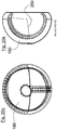
- the joint spacer is configured as a hip spacer and can be put over the femoral head in the form of a cup-shaped elastic coating.
- a hip spacer can be used minimally invasively without any bone resection.
- the hip spacer - preferably in the vicinity of the proximal pole - has an opening for the passage of the H-kopfbandes.
- the hip spacer is separated according to a preferred embodiment of the invention from the opening to the edge of the cup-shaped coating, wherein an overlap region is provided along the dividing line.
- the hipspacer is cut down (caudal) like a "waistband slit" to allow the hipspacer to wrap around the femoral head when the femoral headband has not been severed.
- the outer part of the overlap region has inwardly a plurality of nubs, which are insertable corresponding recesses of the lower part of the overlap region.
- the nubs are preferably arranged along a median arch.
- connection means in the form of "nipples”, “buttons” or snaps, cords or other suitable means for closing and fixing are provided, such as a Velcro or positive connections with hinged joints or snap hooks or other snap connections.
- this is a so-called oblique hook blade, as known from wood joints.
- a cohesive connection by gluing or welding comes into consideration.
- the separation of the H-spacers be closed by stapling or staples.
- a zipper or teeth of prongs is a suitable connection.
- the zipper-like compound is designed in the form of a toothing in puzzle shape.
- the hip spacer is preferably made elastic, it may have a slight undersize relative to the femoral head to positively and non-positively connect the hip spacer with the femoral head.
- the hip spacer may be closed proximally and formed without separation when the femoral head band has been severed.
- the hip spacer can be separated from the equator to the free edge to facilitate slipping over the femoral head.
- the separation may be in the form of a simple cut or with an overlapping area in the form of e.g. be carried out of the waistband slot.
- the free edges of the two poles of the hip spacer may consist wholly or partly of a porous nonwoven layer of feinfibrillärer structure.
- a band or, as in the case of the knee spacer, a tube of fine-fibrillar structure can be connected to the free edge, which optionally extend beyond the ends of the free edge.
- the fine-fibrillar band itself or a fixation band located in the tube can be used to attach the hip spacer around the femoral neck by z. B. Knotting the ends of the bands are used.
- the materials and material structures suitable for the hip spacer are similar to those of the joint spacers or knee spacer and thus to the previous descriptions.
- the hip spacer may also partially consist of degradable material or a matrix in which the surrounding cell and tissue structures grow in and replace or supplement the material or the matrix.
- the shape and concept of the hip spacer may consist of tissue-grown material, that is to say be fabricated by means of tissue-engineered cartilage tissue.
- the hip spacer is - similar to the knee spacer - made of homogeneous or porous material and / or multi-layered structure.
- a sandwich structure of a harder inner core layer and softer outer layers is provided.
- only one inner core layer and one outer soft cover layer may be used.
- the inner side facing the femoral head can adapt particularly well to the topography of the individual femoral head patient when it is particularly soft.
- the inside of the hip spacer could also be attached to the femoral head using a suitable adhesive.
- the underside can be injected with bone cement to compensate for Inkongurenzen between hip spacer and head.
- the inside or the inner layer may also be roughened or consist of a fleece or foam-like structure for a better bond. Bone structures can grow into these porous structures. Therefore, the inside is made of, for example, hydroxylappatite, calcium phosphate, titanium, or another suitable substance that promotes partial bone ingrowth.
- the hip spacer can be designed with the described material and sandwich structures in the form of a socket insert, so that the hip spacer is not placed over the femoral head, but is inserted into the pan of the hip.
- the hip spacer can be used as a damping element for hip endoprostheses in the form of a coating over the head or pan insert.
- the material configurations and sandwich structures embodied in this invention are also useful for other joint spacers that can be used in other joints within (intervertebral disc, shoulder, foot and hand) or outside as orthoses of the human body. They can also be used for joints of animals, such as horses. In harder versions, the materials are also suitable as tendon or ligament replacement such as cruciate ligaments in the knee joint.
- Diagram 1 shows the characteristic range of the tensile stress / strain curves of the preferred materials.
- it shows the 50% tensile stress values for the materials in the Shore A hardness range 20-77, which are greater than 3.8 N / mm 2 , preferably greater than 4.6 N / mm 2 and particularly preferably greater than 6 N / mm 2 should be.
- the diagram also shows a voltage curve with a flow behavior, which should be avoided, unless the yield point would reach very high values greater than 10N / mm 2 .
- the S-curve (“S-curve") illustrates that a suitable material with sufficient 50% tensile stress can have much lower moduli of elasticity and tensile values at strains below 50%, as in the other curves shown.
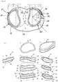
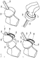
- Fig. 1a-c show different perspective views of a (left) knee joint 10 and portions of a thigh 12 (femur) and a Lower leg 13 (tibia). Between the joint surfaces 14, 14 'meniscus spacers 15, 15' are arranged, which replace the abraded and damaged (natural) meniscus. To protect the material of the meniscus spacer 15, 15 ', the forces to be transmitted must be distributed over as large a load-bearing surface as possible. The shape, in particular the edge contour of a knee spacer 15, 15 'projected onto the tibial plateau 14, therefore plays a central role. The highest loads occur in almost fully stretched leg position, as in Fig. 1b is indicated.
- the stress in the anterior half of a knee spacer 15, 15 ' is highest due to the femoral condyle rising posteriorly with respect to the tibial plateau 14 and the resulting enlargement of the gap 16.
- the bearing surface of the tibial plateau 14 narrows from anterior to posterior by a diminution (the area intercondylar posterior).
- the posterior half of the support surface is used in particular for unrolling the condyles 17, 17 'in more strongly bent positions, in which lower loads occur.
- Fig. 2 shows that the edge contour 20 and thus load-bearing border of the knee spacer 15, 15 'similar to a footprint anterior wider and posterior narrower.
- the anterior half in the illustrated embodiment is 10-25% wider than the posterior half.
- the outer side of the edge contour of the medial as well as the lateral Meniskusspacers along the anterior-posterior axis MA-MP, LA-LP is designed substantially circular arc-shaped (arrow 21).
- the outer side of the edge contour of the lateral Meniskusspacers 15 ' is more closely approximated to a circular arc than the outer edge contour of the medial Meniskusspacers 15 (see arrows 22, 22').
- the circular arc opposite inner side of the edge contour 23, 23 ' is concave from the wider to the narrower part of the support surface.
- the thus formed edge contour 21 of the medial and lateral Meniskusspacers 15, 15 ' adapts to the support surface of the tibial plateau 14 optimally and thus distributes the load to a maximum large area. In addition, the risk of dislocations or jamming is reduced.
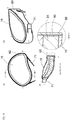
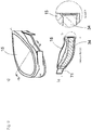
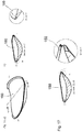
- the meniscus spacer 15 ' is made thicker anteriorly and posteriorly than in the central region of the meniscalus pacer 15 'and at least in an area at the outer edge of the same thickness or preferably thinner than the central area of the Meniskusspacers, wherein the range from the center of the circular edge contour seen from an angle 24 of 90 °, preferably by an angle 25 of 45 °, extends.
- the tibial surface of the meniscal spacer 15, 15 ' is preferably individually adapted to the topography of the patient's tibial plateau.
- the tibial and also femoral surface of the knee - the bone and preferably the cartilaginous layer - is generated from a 3D statistical shape model of a patient group according to population-specific properties.
- a shape model specifies the average shape of a larger number of a group of similar shapes that can be used to show the shape variation of that group.
- the patient groups can be classified according to the classification according to clinical severity of osteoarthritis, also can be averaged by gender or age / weight groups or other criteria such as ethnic origin.
- the knee forms of an individual are generated from CT or MRI scans.
- the misalignment of the respective knee forms involved in the group should be corrected to the most physiological possible leg position. In practice, however, this will depend on the individual circumstances of the patient, in particular of his ligament apparatus or whether this is "loose” or “worn out” or “shrunk together". As a result, for example, a patient with a loose ligament may be more easily transferred to proper leg position by inserting a knee spacer than a patient with a shrunken ligament where the gap to be used for the knee spacer is too small for a normal leg position. The latter criteria must therefore also be taken into account in the generation of 3D shape models in the groups to be classified, for example by predetermined degrees of misalignment of the leg.
- the impression area is at diffraction angles between 6 ° and 28 °, preferably again in the range of the mean value of this angular range.
- the impression of the femoral side preferably results from a plurality of positions of the femur or by turning the femur within the preferred angular range, in which case not the entire angular range mentioned must be molded. This shaping greatly reduces the risk of dislocation.
- Impression of the femoral side may be patient-specific or in accordance with the previously described 3D statistical shape models.
- the latter can then be used to derive prefabricated or prefabricated spacers which on the one hand belong to the respective pronounced 3D shape models and on the other hand are provided in different sizes but also in thicknesses.
- the classification according to thicknesses is done because this unphysiological bending of the leg (valgus / varus) or depending on the patient and its weight and degree of wear of the cartilaginous layer of the knee different joint gaps can be compensated.
- the following method is preferably proposed.
- the leg of the patient firstly standing under load, where the tibia and femur are in contact and the leg has a malposition, and secondly straightened, so with correct leg position, taken, this preferably from the front and side view.
- the resulting gap between the femur and tibia can be used to select the thickness.
- the difference in the distance between the femur and tibia between the two receptacles is used to select the appropriate thickness of the knee spacer. It is advantageous if in this case can be made of simple and cheaper 2D images such as X-rays.
- the Fig. 3 ai show the medial meniscus spacer 15 and the Fig. 4 ai the lateral meniscus spacer 15 '.
- the transitions between the edge surfaces formed by the edge contours 20 and the femoral surfaces 31 of the meniscal nut 15, 15 ' are rounded (arrow 30), as the femur 12 slides over the femoral surface 31 and rolls.
- the transitions between the edge surfaces and the tibial surfaces 32 of the meniscalus spacer can be rounded ( Fig. 4 , Arrow 40) or not be rounded ( Fig. 3 , Arrow 33).
- the latter in particular when the Meniskusspacer 15, 15 'is fixed on the Tibiaplateau 14 and consequently there can be no relative movement between the two.
- the meniscal nut 15, 15 ' should be movable on the tibial plateau 14.
- the height of the lateral edge surface varies along the circumference.
- the marginal areas are on the medial and lateral Meniskusspacer 15, 15 'posterior and anterior higher on average than on the side surfaces, in particular, are the posterior at the transition to the inner edge surface highest.
- the inner peripheral surface of the medial meniscal pusher 15 in the anterior half is near the transition to the posterior half (between sections g and i in FIG Fig. 3 ) thinnest.
- the tibial plateau 14 is inclined in the medial-lateral direction to the plane of the plateau, in particular toward the inner edge, or "downhill" (see FIG. Fig. 1c and sectional view Fig. 3i ).
- the inner edge surface is higher or depending on the wear at valgus position and flattening of the tibial plateau 14 about the same height as the outer edge surface.
- the lateral tibial plateau 14 is concave-shaped and arranged substantially perpendicular to the leg axis (ie, not sloping), whereby the resulting force vector is largely coaxial with the vertical leg position, so that the lateral risk of luxation of the lateral Meniskusspacer is lower.
- the thinnest point or lowest height 41 of the outer edge is characterized, wherein at the same time the thickness at this point is equal to or preferably less than in the central region.
- the tibial surface 32 of the meniscal nut spacer 15, 15 ' is substantially convex and the femoral surface 31 is concave.
- the curvature of the femoral surface 31 of the meniscal nut spacer 15, 15 ' is preferably greater than that of the femoral condyle, so that the meniscal nut spacer 15, 15' is initially loaded at its particularly elastic edges and thus given a high degree of damping.
- the edge surface of the meniscal nut spacer must not run in a "vertical" direction, but may also be set in the plane formed by the leg axis and the anterior-posterior direction (sagittal plane), as in FIG Fig. 5 is shown. Furthermore, the edge surface can also be employed from a manufacturing point of view in such a way that demolding of the spacer from the production tool is facilitated.
- Meniskusspacer 15, 15 'of the natural knee movement adapts to the respective further executed high compliance of the material of the respective flexion of the joint and is self-centering. During normal movement dislocations, as well as movement restrictions or jamming of the spacer with excessive stress and possible damage, can be avoided as far as possible.
- Fig. 3 shows by way of example a spacer with a sandwich structure with a core layer 34 and two cover layers 35, 35 '.
- the tibial cover layer 35 has a uniform configuration of a uniform thickness.
- the core layer 34 closes with almost constant thickness of this cover layer 35 preferably over the entire surface.
- the medial meniscus spacer 15 may in particular be located between the line MA-MP (FIG. Fig. 2 , Line LA-LP at the lateral meniscus spacer) and the inner edge (cf. Fig.
- the core layer 34 does not have to extend completely to the edge of the spacer.
- the tibial covering layer has a thickness of up to about 3 mm, preferably between about 0.2 and 2 mm.
- the core layer 34 has a thickness, preferably in the range of about 3-10 mm, depending on the total thickness of the meniscus spacer 15, 15 'or the knee gap.
- the proximal end of the core layer 34 is followed by the femoral covering layer 35 'having a non-uniform thickness distribution which is relatively thin centrally and has an increasing thickness towards the edge.
- the soft cover layers 35 and 35 'with their thicker edge region can absorb impact loads extremely well.
- the high flexibility of the sandwich structure ensures that the Meniskusspacer 15, 15 'of the knee movement during flexion and extension can adapt very well. This further reduces the risk of dislocation.
- the core layer 34 of the meniscus spacer 15, 15 ' may be thickened toward the outer, circular-arc-shaped edge, for example when the spacer, as described below.
- Fig. 9b is fixed with an additional circumferential band on the tibial plateau 14. This thickening thus forms an additional C-shaped reinforcement of the core layer along its outer edge.
- the outer soft cover layers 35, 35 'of the sandwich structure of a Gelenkspacers 15, 15' further preferably consist of a particularly hydrophilic and / or low-friction or abrasion-resistant material or are additionally coated with a thin layer of such a material.
- a cover layer 35, 35 ' also have a rough surface or with a layer of z.
- Hydroxylappatit be connected so that they can grow together with the surrounding tissue structures or the bone on one side of the joint.
- the above-described sandwich structure or its individual layers preferably consist of homogeneous materials. All or only individual However, layers, preferably the outer cover layers, can also consist of the described porous structures.
- the Gelenkspacer may also have additional intermediate layers to z. B. to achieve a lower gradation of hardness differences or to apply a greater range of hardnesses.
- the individual layers could not be flat, but only connected to each other at their edges or possibly also be mutually displaceable.
- Fig. 4j-l show embodiments of the Meniskusspacers, where only the edge region is formed in a sandwich structure and in the edge region of the spacer consisting of a harder material at least partially over the circumference of a wedge-shaped ring made of a softer material is embedded.
- the edge regions can also be designed differently than shown in the figures, for example, the soft material may be superimposed on the edge harder, or the edge is over the entire thickness of soft material.
- the edge surface of meniscus spacer 15, 15 ' is covered along its entire circumference with a porous fleece layer 60 of fine-fibrillar structure (random fleece) is ( Fig. 6 ) into which surrounding cell or tissue structures grow without forming hardening scarred connective tissue.
- the Meniskusspacer 15, 15 ' can grow together in particular with the capsule of the knee and contribute to the positioning and dislocation reduction in the knee.
- the fine-fibrillar boundary layer 60 is connected to the knee spacer only at the distal and proximal edges ( Fig. 12b , Arrows 120, 121).
- the advantage here is that it comes to small relative movements and thus to a motion compensation between Meniskusspacer 15, 15 'and grown feinfibrillärer boundary layer and thus the positioning of the meniscus spacer is further supported.
- a flat tube 70 of fine-fibrillar structure to be fastened around the edge surface of the meniscalus spacer ( Fig. 11 . Fig. 7 ).
- the tube 70 is intended to fasten the tube 70 only on the outer circular-arc-shaped edge, thereby extending this tube beyond the ends of the circular arc to the inside of the knee ( Fig. 7 ).
- the tube 70 has a C-shape through this configuration in the plan view.
- This fixing strap 71 can also be led out through openings at the corresponding points out of the tube 70 or the fleece border when the tube is placed around the full circumference of the edge face of the meniscalus spacer 15, 15 ' is ( Fig. 8 . Fig. 11 ).
- Fig. 8 shows an embodiment in which the fixing belt 71 extends in a circumferential groove 80 or recess in the core layer 34 and is led out of the fine fibrillar surface layer 60 similarly as described above.
- the fixing band 71 or other reinforcing fibers used in the same way and shape are freely movable in the groove 80, but it can also be integrated and fixed in the core layer 34, as shown in FIG Fig. 9 is shown.
- the core layer 34 is thickened to the outer edge and thus reinforces the suspension by the fixing belt 71.
- the fixing belt 71 may be glued or otherwise attached only around the edge surface of the Meniskusspacers 15, 15 '.
- the fine-fibrillar nonwoven layer is then attached to the edge surface at the distal and proximal edges.
- the fixation band 71 could remain permanently in the knee according to the fixation methods described above, so that only the meniscalus spacer 15, 15 'has to be exchanged during a reoperation.
- the exterior of the L-profile 100 is preferably covered with a fine fibrillar structure.
- the profile 100 is connected to the solid core layer 34 of the meniscus spacer 15, 15 'and consists of a particularly hard polyurethane, a high-strength plastic or a metal.
- the fixation band lying outside the actual meniscus spacer 15, 15 ' 71 and the junction with the Meniskushorn are enclosed by a specific embodiment with the fine fibrillar tube structure.
- the groove 101 is in accordance with the embodiment Fig. 11 integrated in the sandwich structure of the meniscus spacer 15, 15 '.
- Fig. 12 shows a further embodiment of a Meniskusspacers 15, 15 'with a rail 122, wherein this arc-shaped or otherwise form-fitting manner in the edge surface of Meniskusspacers 15, 15' nestles, but is not materially connected to the spacer.
- the profile rail 122 can also extend around the entire edge surface of the meniscus spacer 15, 15 '. By this configuration, the Meniskusspacer 15, 15 'detached from the rail 122 and also lifted out and replaced by another.
- the additional profile rail could also be dispensed with, so that the fixation band is placed in a C-shaped manner around the meniscus spacer with an optionally surrounding fine-fibrillar tube.
- a medial and lateral knee spacer 15, 15 ' are connected to one another via a one- or two-piece fixing strap 71.
- the anterior band end of the one spacer is connected to the posterior end of the other cross.
- a connection of the bands preferably via couplings or snap connections, such as belt buckles, belt snap buckles, tongue and groove buckles over which the bands can be changed in length at the same time.
- the change in length could in this case by means of a separate element, such.
- the listed elements can also be used in the previous versions.
- the fine-fibrillar tube structure could be pushed after the operation of the clutch on this or on the other serving for length change elements in a similar manner as previously described.
- a meniscus spacer 15, 15 ' having at the inner edge 130 and at each end of the outer edge two first inwardly and then distally directed projections 131, 131' which are incorporated in the above-mentioned indentations on the Tibiaplateau 14 form-locking grip.
- These front view L-shaped projections 131, 131 ' are preferably made of the same material as the core layer 34 and are connected thereto.
- the projections 131, 131 'or partial regions of the projections 131, 131' may alternatively also consist of a fine-fibrillar or other suitable structure which makes it possible to sew the projections 131, 131 'with the meniscal horns.
- the protrusions 131, 131 ' may be designed pin-shaped at their ends, that they protrude into holes made at the Einmuldungen and thus prevent dislocation of Meniskusspacers 15,15'.
- Fig. 14 shows the lateral meniscal implant 140, which only replaces the meniscus in the knee. This is like the natural meniscus in the supervision crescent-shaped and cross-sectionally wedge-shaped.
- the surrounding band 141 with tubular outer sheath 142 is formed similar to the Meniskusspacer.
- Fig. 15 shows a preferred embodiment of a lateral "femoral" Gelenk lakespacer 150 for people with osteoarthritis in an early stage, in which the meniscus is still in such a state that it does not or not completely removed.
- the articular surface spacer 150 is placed in the concave trough of the tibial plateau 14, which is formed by the meniscus remaining in the knee.
- This Gelenk perennialspacer 150 is tibial sided therefore bevelled towards the edge, so that the tibial and femoral edge contour merge into each other. A border like the meniscus spacer does not exist.
- the tibial side of the femoral Gelenk lakespacers may also have protuberances to fill partially defective or partially resected menisci.
- the border contour can be rounded ( Fig. 16 , Detail W).
- the Gelenk lakespacer edge of fine fibrillar structure ( Fig. 16 ) consist.
- the inner edge contour may have an edge surface ( Fig. 17 ), so that the merging tibial and femoral edge contour extends only over about 270 °.
- the femoral shape of this articular surface spacer is similar to the femoral side of the meniscalus spacer and is concave.
- the tibial form is convex.
- tibial Gelenk lakespacers as "tibial” Gelenk lakespacer this is essentially in a relatively flat shape or as a disc with almost uniform thickness before, which is placed under the meniscus.
- Fig. 18 shows a lateral tibial Gelenk lakespacer 180. In the medial-lateral direction, however, the cross section may also be pointed-wedge-shaped.
- the tibial surface of this articular surface spacer 180 is similar to the tibial surface of the meniscal nut spacer.
- This embodiment of the Gelenk perennial spacers may have a fine-fibrillar structure edge.
- the marginal fine-fibrillar structure allows the femoral or tibial articular surface spacer to be fixed or sutured to either the upper or lower elevation of the meniscal or capsular structure. Both forms of the articular surface spacer can also be used to straighten bends of the leg (valgus, varus).
- the meniscus or Gelenk vomspacer and in particular their material configurations and sandwich structures are suitable with appropriate shape as a disc-shaped sliding surface for uni- or bicondylar endoprostheses, which are usually made of polyethylene.
- uni- or bicondylar endoprostheses which are usually made of polyethylene.
- two (medial and lateral) discs are also connected at their inner margin, as in an endoprosthesis.
- the bottom of this Slices are usually flat, they can also be different, for example, convex.
- the sandwich structure is also conceivable in such a way that a particularly soft core layer is combined with harder cover layers, wherein the cover layers are particularly slippery.
- the hip spacer 190 ( Fig. 19 ff.) is an elastic covering for the femoral head 191 which is preferably minimally invasive without any bone and minimal tissue resection.
- the hip spacer 190 has approximately at the proximal pole a round or elliptical opening 192 for the passage of the femoral head band 193. Through the opening at the distal pole leads the distal side of the femoral head 191 or 191 beyond the equator the neck of the femur.
- the hip spacer 190 is similar to a "waistband slit" separated (arrow 194) to put the hip spacer 190 around the femoral head 191, when the femoral head band 193 was not separated.
- the hip spacer 190 is separated in the thickness of the waistband slit along a meridian strip, preferably halved.
- the outer half has inwardly a plurality of nubs 195, which engage in openings 196 of the inner half and thus close and fix the hip spacer 190 around the femoral head 191 similar to a buttonhole bar.
- the nubs 195 are arranged in two rows along the median arch. Since the hip spacer 190 is preferably made very elastic, it may have a slight undersize relative to the femoral head 191 in order to fix the hip spacer 190 in a positive and non-positive manner with the femoral head 191.
- the hip spacer 190 may be closed proximally and / or without a slit when the femoral head band has been severed.
- the proximal half of the hip spacer 190 is approximately spherical, on the outside, and spherically to ellipsoidally slightly deformed on the inside. Beyond the equator, the hipspacer externally tapers ellipsoidally inside depending on the cutting plane again slightly deformed spherical to ellipsoidal.
- the hip spacer geometry is preferably composed externally of a spherical and a circular-ellipsoid half-shell. Exemplary diameters here are 58mm for the circular or spherical part and 32mm for the short axis of the ellipsoid. Other absolute sizes and ratios of the diameter are of course possible.
- the hip spacer 190 and thus its geometry and thickness distribution can optionally also be individually adapted to the patient. This could better compensate for incongruities of femoral head and socket, especially of expired pelvic cups.
- the inner surface of the hip spacer located distally of the equator may deviate from a circular shape in order to better conform to the femoral head neck ( Fig. 20c) ,
- the distal half of the femoral head spacer can also lead to the smallest circumference of the femoral neck or complete it beforehand, as in the Fig. 19 and 20 is shown.
- the sandwich structure of the hip spacer is shown.
- the hard core layer can be limited only to a partial surface of the femoral head, which is particularly heavily loaded.
- the core layer is designed in the form of a sphere 200.
- the opening angle of the spherical branch of the particularly viable core layer is less than 125 °, preferably less than 105 °.
- the core layer extends distally beyond the equator, proximally it begins in the region of the proximal opening, so that the closure strip of the H Commonkopfspacers preferably completely made of the softer material.
- the pressure peaks can be cushioned with incompletely covered hip joints, where the maximum pressure can be shifted very close to the edge of the pan. The most loaded Parts of the joint are supported, at the same time the congruence compensation is promoted by the very soft caudal hip spacer half.
- Fig. 21 preferred embodiments are shown.
- Fig. 21 a upper half
- the oblique hook blade 211 is shown in cross-section of the Hntendedtspacers 190, which also forms an overlap region of the separation. Instead of 2 hooks, this can only consist of a hook.
- the hook-blade connection 211 can also be inserted as a prefabricated component in the molding process (for example during injection molding) of the hip spacer 190 into the mold cavity or subsequently glued to the hip spacer 190.
- Fig. 21 a upper half
- the hook-blade connection 211 can also be inserted as a prefabricated component in the molding process (for example during injection molding) of the hip spacer 190 into the mold cavity or subsequently glued to the hip spacer 190.
- FIG. 21 a (lower half) is shown a separation of the H captivetspacers 190 in the form of an oblique section 212, the separating surfaces or the overlap region can be glued or welded here, connected by means of a Velcro fastener, by means of staples or more feasible knobs.
- Fig. 21b is the teeth of tines in puzzle shape (arrow 213) shown. Due to the shape of the undercuts, you can push together the ends, ie the tines, and you do not have to put them together from above - just like with an ordinary puzzle.
Landscapes
- Health & Medical Sciences (AREA)
- Life Sciences & Earth Sciences (AREA)
- General Health & Medical Sciences (AREA)
- Public Health (AREA)
- Oral & Maxillofacial Surgery (AREA)
- Transplantation (AREA)
- Animal Behavior & Ethology (AREA)
- Veterinary Medicine (AREA)
- Chemical & Material Sciences (AREA)
- Orthopedic Medicine & Surgery (AREA)
- Medicinal Chemistry (AREA)
- Dermatology (AREA)
- Epidemiology (AREA)
- Biomedical Technology (AREA)
- Heart & Thoracic Surgery (AREA)
- Engineering & Computer Science (AREA)
- Cardiology (AREA)
- Vascular Medicine (AREA)
- Chemical Kinetics & Catalysis (AREA)
- Physical Education & Sports Medicine (AREA)
- Rheumatology (AREA)
- Dispersion Chemistry (AREA)
- Prostheses (AREA)
- Materials For Medical Uses (AREA)
- Polymers & Plastics (AREA)
- Organic Chemistry (AREA)
- Orthopedics, Nursing, And Contraception (AREA)
- Inorganic Chemistry (AREA)
- Polyurethanes Or Polyureas (AREA)
Abstract
Description
- Die vorliegende Erfindung betrifft ein Polymer für einen Gelenkspacer, insbesondere einen Kniespacer und einen Hüftspacer, Implantate und/oder als Sehnen- oder Bänderersatz aus einem Polyurethan.
- Von Osteoarthrose, dem vorzeitigen Verschleiß knorpeliger Gelenkflächen, sind weltweit viele Millionen Menschen betroffen, der größte Teil davon an den Knien und an der Hüfte. Als Alternative zu den bisherigen mit vielfältigen Nachteilen verbundenen künstlichen Gelenken (Endoprothesen) bieten sich für das Knie elastische, scheibenförmige Abstandshalter, sogenannte "Kniespacer" an. Diese lassen sich mittels eines kleinen Hautschnitts nach der Entfernung des (Rest-) Meniskus, der Glättung der Gelenkflächen und einer sorgfältigen Größenauswahl in den Knieinnenraum einführen. Sie ersetzen im Gelenk den abgeriebenen Knorpel und den beschädigten Meniskus. Die Kniespacer stellen den natürlichen Gelenkspalt wieder her und können so auch Abwinklungen, wie beispielsweise X- oder O-Fehlstellungen (Valgus, Varus) des Beines, korrigieren.
- Die natürlichen medialen (innen) und lateralen (außen) Menisken sind halbmondförmige Faserknorpelgewebe, die im Querschnitt keilförmig sind und über das Vorder- und Hinterhorn im Tibiaplateau verankert sind. Sie vergrößern die Kontaktfläche zwischen dem Tibiaplateau und den Gelenkrollen (Kondylen) des Femurs (Oberschenkelknochen).
- Gelenkspacer bezeichnen allgemein Abstandshalter, die auch in anderen Gelenken, wie beispielsweise der Hüfte, der Schulter, dem Fuß, der Hand oder der Wirbel des menschlichen Körpers eingesetzt werden können. Gelenkspacer beinhalten hier auch sogenannte "Plugs" oder flache Stöpsel, welche nur einen kleinen Teil der Knorpelfläche eines Gelenks ersetzen können. Zudem sind Abstandshalter als Gleit- und Dämpfungselemente für Endoprothesen einsetzbar. Bei Kniespacern wird zwischen verschiedenen Ausführungsformen unterschieden. Der Meniskusspacer ersetzt den Meniskus und abgelaufenen Knorpel der Gelenkflächen und das Meniskusimplantat lediglich den Meniskus. Der Gelenkflächenersatz oder Gelenkflächenspacer gleicht den teilweise abgelaufenen Knorpel bzw. den beginnenden Verschleiß des Knorpels der Gelenkflächen ohne Ersatz des Meniskus aus.
- Es ist bekannt, dass Kniespacer aus unterschiedlichen Materialien und Polymeren bestehen können. Dabei sind Polyurethane aufgrund ihrer hohen mechanischen Festigkeit und hohen Abriebfestigkeit sehr gut geeignet. Grundsätzlich kann bei Polyurethanen zwischen aromatischen und aliphatischen Polyurethanen unterschieden werden. Aromatische Polyurethane besitzen üblicherweise die größere mechanische Festigkeit und scheinen daher besser geeignet für die hohen Belastungen, die in einem Kniespacer während der Beugung und der Streckung auftreten. Aromatische Polyurethane haben gegenüber aliphatischen jedoch den Nachteil, dass sie "vergilben" können, also einen gewissen Alterungseffekt zeigen. Zudem stehen aromatische Polyurethane in der Diskussion, dass ihre potenziellen Abbauprodukte ein kanzerogenes Risiko besitzen können.
- Kniespacer haben sich bis heute noch nicht durchsetzen können, weil die Implantate häufig brechen, aus dem Gelenkspalt des Knies herausrutschen oder Bewegungseinschränkungen auftreten. Insbesondere sind derzeit keine Kniespacer mit physiologischer Dämpfung bei gleichzeitig ausreichender mechanischer Festigkeit und Dauerfestigkeit bekannt. Insbesondere eine physiologische Dämpfung ist jedoch erstrebenswert, da sie zu einer Schmerzfreiheit des Patienten führt.
- Es ist die Aufgabe der vorliegenden Erfindung, ein Polymer für einen haltbaren, ausreichend gedämpften und abriebfesten Gelenkspacer zu schaffen, der auch punktuell sehr hohe Lasten aufnehmen kann. Die aus dem Polymer gemachten Gelenkspacer sollten zudem eine möglichst hohe Kongruenz zwischen den artikulierenden Gelenkflächen erzielen und nicht aus dem Gelenkspalt herausrutschen können. Das Polymer soll auch für Implantate und/oder als Sehnen- oder Bänderersatz geeignet sein.
- Diese Aufgabe wird durch das Polymer für einen Gelenkspacer nach Anspruch 1 gelöst. Erfindungsgemäß ist das Polyurethan des Polymers ein Polyurethanharnstoff oder Polyharnstoff, wobei als Vernetzungsreagenz Wasser oder Wasser in Kombination mit einem oder mehreren weiteren Kettenverlängerern und/oder Vernetzungsreagenzien eingesetzt wird.
- Ein solches Polymer, insbesondere für einen Gelenkspacer zeigt vorteilhafterweise ein ausgeprägtes progressives Druck-Stauchungsverhalten. Mit zunehmender Stauchung nimmt nämlich die Elastizität überproportional ab und das Polymer wird mithin härter. Mit anderen Worten das Material ist hinsichtlich seiner Shore-Härte relativ weich und besitzt quer zur Stauchung gleichzeitig einen relativ hohen Elastizitätsmodul.
- Außerdem eignen sich die beschriebenen Polymere für weitere Implantate des menschlichen Körpers, wie beispielsweise für Gefäße, Herzklappen und sonstige Ventile im menschlichen Körper sowie für Pumpenmembranen und -kammer in künstlichen Herzen und Herzunterstützungssystemen. Des Weiteren sind sie für ophthalmologische Implantate wie Intraokularlinsen oder künstliche Hornhäute geeignet.
- In den Unteransprüchen sowie nachfolgend werden bevorzugte Ausgestaltungen der Erfindung beschrieben.
- Im Zusammenhang mit der Auswahl geeigneter Materialien bzw. Polymere für Gelenkspacer wird häufig die Shore-Härte herangezogen. Die in den Gelenken, besonders in Knie und Hüfte, auftretenden sehr hohen Belastungen können unter den bekannten für die Medizintechnik geeigneten Materialien nur durch Materialen mit Shore-A-Härten oberhalb von 85 aufgenommen werden. Für eine hohe Kongruenz und Dämpfung und letztlich damit Schmerzfreiheit für den Patienten wären Gelenkspacer aus solchen Materialien jedoch im Knie zu hart und daher weniger geeignet. Je weicher der Gelenkspacer, desto größer ist die Kontaktfläche zwischen Gelenkspacer und Gelenkfläche und desto kleiner die Spannung und damit auch der Abrieb im Gelenkspacer. Der Gelenkspacer sollte idealerweise in seiner Komplianz dem natürlichen Gelenkknorpel angenähert sein. Dies schließt den geschwächten arthrotischen Gelenkknorpel ein, so dass dieser nach Möglichkeit nicht weiter durch das Implantat geschädigt werden kann. Es wird ein Shore-A-Härte Bereich des Materials von 20 bis 77, vorzugsweise von 45 bis 72 angestrebt. Für sehr schwergewichtige Menschen, abhängig von der Größe der Tibiafläche bzw. des Gelenkspacers ab ca. 100-120 kg, kann darüber hinaus die Shore-A-Härte des Materials bis 85 liegen. Hierzu kommen als Materialien in erster Linie Elastomere oder thermoplastische Elastomere in Frage. Die bekannten flexiblen Polymere bzw. sonstigen Materialien in diesem Härtebereich können bei höheren Verformungen nicht genügend Spannung aufbauen, um den auftretenden Kräften in den Gelenken standzuhalten, d.h. die Tragfähigkeit des Lagermaterials reicht nicht aus. Es hat sich in Versuchsreihen jedoch gezeigt, dass Materialien, die ein ausgeprägt progressives Druck-Stauchungsverhalten aufzeigen, für Gelenkspacer geeignet sind. Materialien können nämlich bei gleicher Shore-Härte sehr unterschiedlich hohe Elastizitätsmodule aufweisen, und insbesondere bei einer vorgegebenen Dehnung oder Stauchung unterschiedlich hohe Spannungen aufbauen. Anders ausgedrückt wird unter einer vorgegebenen Last das Material bei gleicher Shore-A-Härte weniger oder mehr gestaucht.
- Materialien, insbesondere Elastomere und thermoplastische Elastomere können bei Temperaturerhöhung, nach Aufnahme von Wasser und längerer, mehrmonatiger Lagerung in Wasser oder bei mehrfacher Belastung (belastungsinduzierte Entfestigung oder sogenannter Mullins-Effekt) erweichen (Geary C et al. Characterisation of Bionate polycarbonate polyurethanes for orthopaedic applications. J Mater Sci: Mater Med 19 (2008) 3355-3363). Zudem können sich durch Sterilisation die mechanischen Eigenschaften verändern. Weiterhin können sich Materialien bei sehr hohen Prüfgeschwindigkeiten verfestigen. Die in dieser Erfindung angegebenen Parameter beziehen sich daher auf Prüfbedingungen der Proben in einem konditionierten Zustand bei 37°C, nach Aufnahme von Wasser bzw. Gelenkflüssigkeit und mit den üblichen Prüfgeschwindigkeiten der einschlägigen Normen und in einem sterilisierten Zustand. Die Spannungswerte werden vorzugsweise nach dem 5. Zyklus ermittelt, um den Mullins Effekt auszugleichen, da sich die Größe der Hysterese insbesondere in den ersten Zyklen stark ändern kann. Zudem sollten die zuvor angegebenen Werte auch nach mindestens 5 monatiger Lagerung in Wasser erreicht bzw. überschritten werden. Die Materialien sollten also hydrolytisch möglichst stabil sein. Allgemeiner ausgedrückt, sollen die eingesetzten Materialien die Parameter auch nach längerer Implantation im Körper beibehalten.
- Vorzugsweise besteht daher das Polymer oder der Gelenkspacer zumindest teilweise aus einem Material, insbesondere einem Elastomer oder thermoplastischen Elastomer mit einer Shore-A Härte zwischen 20 und 77 und Zugspannungswerten bei Dehnung zwischen 20% und 60% , vorzugsweise bei 50% (im folgenden auch 50%-Zugspannung genannt), größer 3,8 N/mm2, vorzugsweise größer 4,6 N/mm2 und besonders bevorzugt größer 6 N/mm2, und/oder einer Shore-A Härte bis 85 und Zugspannungswerten bei Dehnungen zwischen 20% und 60% , vorzugsweise bei 50%, größer 6 N/mm2, vorzugsweise größer 7 N/mm2 und besonders bevorzugt größer 8 N/mm2. Angemerkt ist hier, dass unter dem Spannungswert bei einer bestimmten Dehnung nicht der Tangenten- oder Sekantenmodul verstanden wird. Das Material sollte außerdem bevorzugt kein Fließverhalten bis 50% Dehnung, vorzugsweise bis 70% Dehnung aufweisen.
- Vorzugsweise weist das Material bei einer Shore-A Härte zwischen 20 und 77 Zugspannungswerte bei 100%-Dehnung (100%-Zugspannung) von mindestens 5 N/mm2, vorzugsweise mindestens 6 N/mm2 und besonders bevorzugt mindestens 7,5 N/mm2, oder bei einer Shore-A Härte bis 85 Zugspannungswerte bei 100%-Dehnung von mindestens 7,5 N/mm2, vorzugsweise mindestens 8,5 N/mm2 und besonders bevorzugt mindestens 10,5 N/mm2 auf.
- Eine weitere Kenngröße für geeignete Materialien sind die Druckspannungen, auch wenn die Schädigung des Materials deutlich mehr von den auftretenden Zugspannungen hervorgerufen wird. Vorzugsweise besteht daher das Polymer oder der Gelenkspacer ferner zumindest teilweise aus einem Material mit einer Shore-A Härte zwischen 20 und 77 und Druckspannungswerten bei Stauchungen zwischen 20% und 60%, vorzugsweise bei 50% (im folgenden auch 50%-Druckspannung genannt), größer 7,8 N/mm2, vorzugsweise größer 9 N/mm2 und besonders bevorzugt größer 10,5 N/mm2, und/oder einer Shore-A Härte bis 85 und Druckspannungswerten bei Stauchungen zwischen 20% und 60%, vorzugsweise bei 50%, größer 10,5 N/mm2, vorzugsweise größer 12 N/mm2 und besonders bevorzugt größer 14 N/mm2 bestehen.
- Die zuvor genannten Spannungswerte können auch bereits bei niedrigeren Dehnungs- bzw. Stauchungswerten als den genannten Werten erreicht werden, auch wenn das Polymer oder der Gelenkspacer dann bei gleichen Belastungen nicht so stark zusammengestaucht wird.
- Wie zuvor angedeutet, können weichere Materialien zumeist den in den Gelenken auftretenden Belastungen nicht standhalten. Neben den zuvor beschriebenen Zugspannungswerten bei 50%- oder auch 100%-Dehnung und den 50%-Druckspannungen ist die Weiterreißfestigkeit ein weiterer wichtiger Materialparameter. Je weicher das Material ist, desto höher sollte idealerweise die Weiterreißfestigkeit sein, mit anderen Worten soll sie umgekehrt proportional zur Shore-A-Härte stehen. Bezugswerte dieser Beziehung sind: bei einer Shore-A-Härte von 55 soll die Weiterreißfestigkeit größer 60N/mm (vorzugsweise größer 70 N/mm) sein, bei einer Shore-A-Härte von 75 größer 35 N/mm (vorzugsweise größer 40 N/mm). Über diese Bezugswerte soll ein linearer Verlauf über die Shore-A-Härte Bereiche bestehen. Die Weiterreißfestigkeiten beziehen sich auf Probenformen gemäß dem "Trouser Tear Test".
- Als Materialien für die Gelenkspacer eignen sich biokompatible und elastische, dauerfeste Polymere und hier, wie bereits ausgeführt, insbesondere die Klasse der Polyurethane. Allerdings können auch andere Werkstoffe verwendet werden, wie beispielsweise Silikone, PTFE, Polysulfone, Polyvinylalkohol, Poly[Styrol-Block-Isobutylen-Block-Styrol] (SIBS, poly[styrene-block-isobutylene-block-styrene]), hydrogenierte Styrene-Block-Copolymere (SBS, SIS, SEBS) oder andere aus dem Stand der Technik bekannte Polymere. Zudem sind neben diversen Kautschuken auch Seide bzw. künstliche Seide für die Gelenkspacer geeignet. Angemerkt sei ferner, dass auch Materialien mit hoher Wasseraufnahme in der Größenordnung von 100% und mehr als geeignete Werkstoffe für die Gelenkspacer in Frage kommen. Ferner sollen die Polymere möglichst frei sein von niedermolekularen Bestandteilen, wodurch die gewünschten 50%-Spannungswerte gesteigert werden und damit zu den bevorzugten Eigenschaften führen.
- Vorzugsweise besteht das Elastomer oder thermoplastische Elastomer des Gelenkspacers aus der Klasse der Polyurethane und insbesondere aus einem Polyurethan, Polyharnstoff oder Polyurethanharnstoff.
- Polyurethane sind charakterisiert durch das Zusammenspiel von Hart- (gebildet aus einem Isocyanat mit niedermolekularen Kettenverlängerern) und (höhermolekularen) Weichsegmenten. Abhängig von ihrer Zusammensetzung zeigen Polyurethane ein sehr unterschiedliches Werkstoffverhalten, insbesondere im Spannungs-/Dehnungsverlauf.
- Isocyanate werden in der Literatur vielfältig beschrieben und können grundsätzlich alle eingesetzt werden. Bevorzugt werden jedoch kompakte, wenig verzweigte und hochschmelzende Isocyanate wie Cyclohexandiisocyanat (CHDI), Naphthalin-1,5-Diisocyanat (NDI), oder Para-Phenylendiisocyanat (PPDI). Ferner eignen sich lineare, symmetrische Isocyanate wie Hexamethylendiisocyanat (HDI). Derartige Ausgangskomponenten begünstigen weiter das progressive Druck-Stauchungsverhalten, woraus sich die genannten Vorteile ergeben. Zudem sind diese Isocyanate besonders gut geeignet für dynamische Anwendungen. Die Gewichtsanteile dieser Isocyanate betragen bis zu 50% vorzugsweise 3% - 30% der Polymere. Diese bevorzugten Isocyanate können ferner mit weiteren aromatischen oder aliphatischen Isocyanaten gemischt werden. Den zuvor genannten Diisocyanaten oder Mischungen aus Diisocyanaten können auch Polyisocyanate hinzugefügt werden.
- Nach einer bevorzugten Ausgestaltung der vorliegenden Erfindung ist vorgesehen, dass das Polyurethangemisch zumindest teilweise trans-1,4-Cyclohexandiisocyanat (CHDI), cis-CHDI oder Mischungen hiervon besitzt. Trans-CHDI ist dabei besonders bevorzugt, weil das Polymer dadurch eine besonders hohe Kristallinität aufweist und damit die bevorzugten Eigenschaften erhält. CHDI führt zudem zu den favorisierten aliphatischen Polyurethanen. Ferner ist vorgesehen, dass das Polyurethangemisch zumindest teilweise aus weiteren aliphatischen Isocyanaten besteht, insbesondere aus Dicyclohexylmethandiisocyanat (H12MDI) oder einem Isomerengemisch hiervon, oder auch einem Gemisch aus CHDI und H12MDI.
- Im Folgenden werden eine Reihe von Formulierungen bzw. Komponenten angegeben, die alle für sich vorteilhafterweise zu den bevorzugten Eigenschaften führen.
- Zur Erzielung des gewünschten progressiven Druck-Stauchungsverhaltens von Polyurethanen mit hohen Spannungswerten bei 50%-Dehnung oder Stauchung und niedriger Shore-A-Härte sind die Weichsegmente von entscheidender Bedeutung. Vorzugsweise kommen für das Polymer oder die Gelenkspacer hydrolysefeste und biostabile Weichsegmente auf Basis von Polyolefinen wie insbesondere Polyisobutylen (PIB) oder Polybutadien (PB) in Frage. Ferner gelten auch Weichsegmente auf Basis von Polycarbonat (PC) und Polydimethylsiloxan (PDMS) als relativ hydrolysefest. Typische aus der Literatur bekannte bzw. kommerzielle, auch medizinische Polyester- oder Polyetherurethane sind für Langzeitimplantate nicht genügend biostabil und kommen daher für das Polymer oder die Gelenkspacer weniger bzw. nicht bevorzugt in Frage, auch wenn sie in relativ kleinen Anteilen beigemischt werden können. Auch Silikon-Ether-Polyurethan Copolymere scheinen eine ungenügende Biostabilität zu haben.
- Nach einer bevorzugten Ausgestaltung der vorliegenden Erfindung ist das Weichsegment des Elastomers oder thermoplastischen Elastomers ein Polyisobutylen (PIB) bzw. ein bifunktionelles Polyisobutylen, bevorzugt ein hydroxylterminiertes (HO-PIB-OH) oder ein aminterminiertes (H2N-PIB-NH2) Polyisobutylen.
- In einer anderen bevorzugten Ausgestaltung ist das Weichsegment Polybutadien (PB), bevorzugt OH-terminiertes und besonders bevorzugt OH-terminiertes hydrogeniertes Polybutadien. Es können jedoch auch aminterminierte Polybutadiene eingesetzt werden.
- Die vorteilhaften Eigenschaften des Polymers werden besonders hoch, wenn das Weichsegment ausschließlich aus einem PIB oder PB oder auch aus einer Mischung dieser beiden Weichsegmente besteht.
- Für das Weichsegment aminterminiertes PIB eignen sich als Kettenverlängerer Ethylendiamin (EDA) oder 1,4-Diaminobutan (BDA) und bevorzugt 1,6-Diaminohexan (HDA) oder 1,8-Diaminooctan (ODA). Das hydroxylterminierte PIB lässt sich besonders gut mit dem Kettenverlängerer 1,6-Hexandiol (HD) kombinieren. Bei Verwendung dieser Kettenverlängerer können die Weichsegmente jeweils sehr gut mit anderen Weichsegmenten gemischt werden, um das Werkstoffverhalten gezielt zu modifizieren und einzustellen. Vorzugsweise wird hierbei H12MDI verwendet, es können jedoch auch die genannten anderen Isocyanate eingesetzt werden.
- Das hydroxylterminierte PIB ergibt ferner mit dem Kettenverlängerer Butandiol ein geeignetes Polyurethan, wenn als Katalysator 1,3-Diacetoxy-1,1,3,3-Tetrabutyldistannoxan (DTDS) eingesetzt wird. Hierbei kann das Polymer auch in einem 1-Schritt-Polymerisationsverfahren synthetisiert werden, ohne das sogenannte Prepolymerverfahren, welches ansonsten in dem 2-Schritt-Verfahren bevorzugt verwendet wird. Als Isocyanat eignet sich neben den bevorzugten Isocyanaten besonders 4,4'-Diphenylmethandiisocyanat (MDI).
- Das Weichsegment PB, insbesondere das hydroxylterminierte hydrogenierte Polybutadien lässt sich vorzugsweise mit den Kettenverlängerern N,N-Diisopropanol Anilin (DIPA) oder 2-Ethyl-1,3-Hexandiol (EHD), es gehen jedoch auch 2,2,4-Trimethyl-1,3-Pentandiol (TMPD) oder 2-Butyl-2-Ethyl-1,3-Propandiol (BEPG). Mit diesen Kettenverlängerern kann das Weichsegment wiederum mit anderen Weichsegmenten gemischt werden. Vorzugsweise wird hierbei MDI verwendet, es können jedoch auch die anderen genannten Isocyanate zur Anwendung kommen.
- Polyurethane sind zudem besonders gut geeignet und führen zu den vorteilhaften Materialeigenschaften, wenn für die Polymerisation der Katalysator 1,3-Diacetoxy-1,1,3,3-Tetrabutyldistannoxan (DTDS) eingesetzt wird. Hierbei ist, wie zuvor ausgeführt, das 1-Schritt-Polymerisationsverfahren sehr gut geeignet.
- Nicht zuletzt können die Polyurethantypen auch vernetzt sein. Hierfür eignet sich vorzugsweise Wasser für die Erzielung der gewünschten Eigenschaften. Es können jedoch weitere Vernetzungsreagenzien wie z.B. 3-wertiges Glycol oder sonstige mehrwertige aus der Polyurethanchemie an sich bekannte Vernetzungsreagenzien eingesetzt werden.
- Bevorzugte Isocyanate bei der Wasservernetzung sind HDI, NDI, PPDI oder CHDI. Bevorzugte Weichsegmente sind hierbei neben den zuvor genannten bevorzugten Weichsegmenten PIB und PB auch Polycarbonatdiol (PCD) und zudem gegebenenfalls als Kettenverlängerer Butandiol (BD) oder ein oder mehrere andere Kettenverlängerer. Vorzugsweise wird jedoch auf einen weiteren Kettenverlängerer verzichtet, also nur Wasser zur Vernetzung eingesetzt.
- Bei Polyurethanen auf Basis von Polycarbonatdiolen wird in der Medizintechnik üblicherweise Polyhexamethylencarbonatdiol (C6-PCD) eingesetzt. Diese sind ausschließlich aus jeweils sechs Methylengruppen (CH2) zusammengesetzt. Um jedoch weichere Polyurethane zu erzielen, zugleich aber die vorteilhaften Materialeigenschaften zu erzielen, die für das Polymer oder die Gelenkspacer besonderes gut geeignet sind, werden Polycarbonatdiol-Copolymertypen (Polyalkylen-Carbonatdiole) statt eines homogenen C6-PCD eingesetzt, die aus den Einheiten Hexan (C6), Pentan (C5), Butan (C4) oder Propan (C3) aufgebaut sind. Vorzugsweise bestehen die Copolymertypen aus den Kombinationen mit C6/C5 oder C6/C4 oder C4/C3 Einheiten, in der chemischen Summenformel ausgedrückt mit

- Eine bevorzugte Formulierung sieht daher vor, dass das Polymer des Gelenkspacers zumindest teilweise Polycarbonatdiol-Copolymere enthält.
- Besonders bevorzugte Komponenten des Polyurethansystem sind, wie bereits ausgeführt, die Isocyanate HDI, CHDI, PPDI oder NDI sowie als Weichsegmente Polyolefine, bevorzugt PIB oder PB und PCD, wobei bei PCD vorzugsweise die zuvor genannten Polycarbonatdiol-Copolymertypen eingesetzt werden. Hierbei wiederum können die Polyolefintypen PIB oder PB gemischt oder jeweils insbesondere mit dem PCD gemischt werden, um besonders abriebfeste Polyurethantypen zu erzielen. Der Anteil von PCD am Gesamtweichsegmentanteil beträgt bis zu 80%, vorzugsweise 5 bis 40%. Die Weichsegmente können ferner mit weiteren bekannten Weichsegmenten wie insbesondere Polydimethylsiloxan (PDMS) oder Polytetramethylenoxid (PTMO) gemischt werden. Auch eignet sich zur Erzielung der vorteilhaften Eigenschaften die Beimischung von Polydimethylsiloxan-Polycaprolacton-Blockcopolymeren. Die Anteile dieser Weichsegmente am Gesamtweichsegmentanteil betragen bis zu 50%, vorzugsweise 3 bis 35%.
- Eine weitere vorteilhafte Formulierung sieht vor, dass das Polymer des Gelenkspacers als Weichsegmente ausschließlich hydroxyl- und/oder aminterminiertes Polyisobutylen, und/oder hydroxyl- und/oder aminterminiertes und bevorzugt hydroxylterminiertes hydrogeniertes Polybutadien, und/oder Polycarbonatdiol enthält.
- Bei den zuvor genannten amin- oder hydroxylterminierten PIB kann es sich zudem um lineare oder verzweigte PIB's handeln. Bei den Polybutadienen können auch Copolymerisate wie Acrylnitril-Butadien-Styrol eingesetzt werden.
- Ferner können auch die zuvor genannten Isocyanate mit anderen aromatischen oder aliphatischen bzw. cycloaliphatischen Isocyanaten gemischt werden, wie beispielsweise 3,3'-Dimethyl-4,4'-biphenylendiisocyanat (TODI).
- Außerdem können in den zuvor aufgezeigten Formulierungen die genannten Kettenverlängerer auch in Kombination zweier oder mehrerer Kettenverlängerer und/oder Vernetzungsreagenzien (z. B. Glycol) in die Polymersynthese eingebracht werden.
- Um die Zug-, die Weiterreiß- und insbesondere auch die Abriebfestigkeit des verwendeten Materials zu verbessern, ist nach einer vorteilhaften Ausgestaltung der Erfindung vorgesehen, dass das Material bzw. bevorzugte Polyurethangemisch Nanoadditive aufweist, die zumindest in einer Dimension wesentlich größere Abmessungen als in ihren beiden anderen Dimension aufweisen. Bevorzugt sind die Nanoadditive scheibenförmig oder flach ausgestaltet bzw. weisen in 2 Dimensionen wesentlich größere Abmessungen als in ihrer 3. Dimension auf. Vorzugsweise besitzen die Nanoadditive eine Breite von 10 nm bis 50 nm, vorzugsweise von 25 nm bis 30 nm, und eine Dicke von 0,5 nm bis 1,5 nm, vorzugsweise von 1 nm. Dadurch wird einerseits das progressive Druck-Stauchungsverhalten verbessert und andererseits die Kriechneigung verringert. Bei Nanoadditiven mit den angegebenen Abmessungen verhärtet das Material nicht, die Shore-Härte bleibt nahezu konstant, was aufgrund der verlangten Komplianz/Dämpfung des Polymers oder des Gelenkspacers erwünscht ist. Durch die Zugabe der Nanoadditive erhöhen sich jedoch die 50%-Zug- oder Druckspannungswerte der Polymere. Die Nanoadditive werden bevorzugt in Volumenkonzentrationen von weniger als 10%, vorzugsweise weniger als 5%, weiterhin besonders bevorzugt weniger als 3%, hinzugefügt. Geeignete Materialien der Nanopartikel sind insbesondere geschichtetes Silikat, diverse Metalloxide, Kohlenstoff- oder Bornanopartikel, zudem auch Titan-, Platin-, Silber- oder Goldpartikel. Es können jedoch auch Kohlenstoff-Nanoröhrchen oder andere faserige Nanopartikel hinzugefügt werden. Ferner können prinzipiell auch langfaserige Verstärkungen im Material des Polymers oder des Gelenkspacers eingearbeitet sein.
- Mit den zuvor aufgezeigten Ausgestaltungen des Materials, d.h. je nach genauer Zusammensetzung der einzelnen Komponenten des Polyurethansystems und/oder der Zugabe von Nanopartikeln können 50%-Zugspannungen bis 20 N/mm2 in den genannten Shore-A-Härtebereichen erzielt werden.
- Zur Verbesserung der Gleiteigenschaften bzw. zur Reduzierung des Reibwertes ist vorgesehen, dass das Polyurethangemisch zudem Polyvinylpyrrolidon (PVP), Polyvinylalkohol (PVA) oder auch andere hydrophile Polymere bzw. dazu geeignete Substanzen aufweisen kann. Der Anteil dieser Substanzen liegt dabei unter 10%, vorzugsweise unter 3%.
- In einer weiteren Ausführungsform der vorliegenden Erfindung besitzt zur Verbesserung des progressiven Druck-Stauchungsverhalten das verwendete Material, Polymer oder Polyurethangemisch eine Schaumstoff- bzw. Porenstruktur, wobei vorzugsweise das Material nach Konditionierung die zuvor genannten Spannungswerte bei 50%-Dehnung oder Stauchung in den relevanten Shore-A-Härte Bereichen aufweisen sollte. Die Porenstruktur kann grundsätzlich offenporig in Form im Wesentlichen einer Wabenstruktur oder geschlossen porig wie eine klassische Blasen- oder Schaumstoffstruktur sein. Versuche haben gezeigt dass Porengrößen in der Größenordnung von 200µm, wie sie häufig z.B. in Polyurethanschäumen auftreten, relativ schnell zu einer Schädigung des Polymer oder des Gelenkspacers führen. Wesentlich besser geeignet sind Poren kleiner 5µm und nanoporöse Strukturen. Durch die Wasser- bzw. Gelenkflüssigkeitsaufnahme in die Poren werden auch schwächere Materialien, die die zuvor aufgezeigten Parameter nicht erfüllen, verstärkt und können damit höhere Lasten aufnehmen. Prinzipiell sind geschlossenporige Schaumstoffstrukturen für die Dauerfestigkeit vorteilhaft, jedoch haben gemischtzellige Strukturen den Vorteil, dass diese Flüssigkeiten aufnehmen können und der Flüssigkeitsaustausch zwischen den Zellen vereinfacht wird.
- Vorteilhafterweise besitzt das Polymer oder der Gelenkspacer daher zumindest teilweise eine Schaumstoffstruktur mit Porengrößen von 0,1 nm bis 2 µm, vorzugsweise von 1 nm bis 500 nm und besonders bevorzugt von 5 nm bis 200 nm. Größere Poren als 2 µm, insbesondere 5 µm führen zumeist zu einem frühzeitigen Verschleiß bzw. zur Schädigung des Polymers oder des Gelenkspacermaterials. Zudem halten insbesondere offene Porenstrukturen mit Porengrößen kleiner 100 nm bis 200 nm Bestandteile, wie z.B. Proteine der Synovialflüssigkeit zurück, um eine Verhärtung oder auch Verkalkung der Strukturen zu vermeiden. Die poröse Struktur hat ferner den Vorteil, dass sich aufgrund der Flüssigkeitsaufnahme in den Poren auf der Oberfläche bei Belastung ein Tragfilm (Flüssigkeitsreibung) aufbauen kann. Anders ausgedrückt kann bei porösen Oberflächen eine Depotschmierung entstehen. Das Polymer oder der Gelenkspacer soll daher an der Oberfläche vorzugsweise offenporig sein. Das Polymer oder der Gelenkspacer kann jedoch auch kaschiert sein, d.h. an der Oberfläche ohne Poren vorliegen. Zur Verbesserung der Gleiteigen-schaften bzw. um eine Flüssigkeitsreibung zu erzielen, kann auch nur die Oberfläche des Polymers oder des Gelenkspacers ganz oder teilweise porös ausgebildet oder aufgeraut sein.
- Die zuvor genannten Stoffe zur Verbesserung der Gleiteigenschaften bzw. zur Reduzierung des Reibwertes, wie Polyvinylpyrrolidon (PVP), Polyvinylalkohol (PVA) oder weitere geeignete Substanzen, können auch genutzt werden, um die Poren der Schaumstoffstruktur zu füllen oder zumindest zu benetzen und damit eine Depotschmierung zu erzielen.
- Wie zuvor beschrieben, verbessern Nanopartikel sowie poröse Strukturen das progressive Druck-Stauchungsverhalten. Darüber hinaus verstärken sich die erzielten Effekte bei Kombination aus Poren und Nanopartikeln und es lassen sich besonders hohe 50%-Zug- oder Druckspannungswerte bei niedrigen Shore-A-Härten für das Polymer oder Gelenkspacer realisieren.
- Eine andere Ausführung zur Erzielung der gewünschten vorteilhaften Materialeigenschaften sieht eine poröse Vlies Struktur oder insbesondere Nano-Vlies Struktur vor, die vorzugsweise aus Fasern mit einem Durchmesser von 0,1 µm bis 0,4 µm besteht. Das Material besitzt eine feinfibrilläre Struktur (Wirrvlies) aus Fasern, die vorzugsweise gesponnen werden und an ihren Kreuzungspunkten gefügt bzw. miteinander verschmolzen sind. Weiterhin sollten die Poren einer solchen Vliesstruktur vorzugsweise kleiner 5µm und besonders bevorzugt kleiner 1 µm sein.
- Der Vollständigkeit halber sei hinzugefügt, dass das progressive Druck-Stauchungsverhalten des Polymers oder des Gelenkspacers mit schaum- oder vliesartiger Struktur und den oben angeführten Shore-A-Härten und 50%-Zug- oder Druckspannungen vorzugsweise erreicht wird, wenn die verwendeten Polymere in homogener oder kompakter Form deutlich härter sind. Anders ausgedrückt können auch Materialien oder Polymere mit Shore-A Härten größer als 77 oder 85 für einen Gelenkspacer besonders gut geeignet sein, wenn sie durch eine poröse Struktur weicher werden und damit die gewünschten Shore-A-Härten erreichen.
- Insbesondere bei Kniespacern wird aufgrund der Konvexität der Kondylen des Femurs der zentrale Bereich des Gelenkspacers stark belastet. In Literatur und Patentschriften werden jedoch Kniespacer beschrieben, deren zentraler Bereich weicher und deren Randbereich härter ausgeführt sind. Allerdings neigen Kunststoffe zum Kriechen, wodurch der zentrale Bereich des Gelenkspacer bei dauernder Belastung "ausgebügelt" wird, also zentral wellig wird bzw. Falten werfen kann, die insgesamt zu Verwerfungen und zu Luxationen des Gelenkspacers führen können. Zudem können so die Randbereiche mit der Zeit immer weniger Last aufnehmen. Um einen Gelenkspacer mit den bevorzugten Dämpfungseigenschaften (Komplianz) zu erhalten, ist in einer weiteren Ausführungsform vorzugsweise zentral härteres und in den Randbereichen des Gelenkspacers weicheres Material angeordnet. Der Meniskusspacer ist so ausgelegt, dass zuerst die weicheren Randbereiche durch den Femur und anschließend der härtere zentrale Bereich belastet werden, wodurch das progressive Druck-Stauchungsverhalten erreicht wird. Die femurale Seite des Meniskusspacers ist dabei konkaver ausgebildet als die Konvexität des Femurs, d.h. bei Kontakt werden zuerst die Randbereiche des Meniskusspacers durch den Femur berührt.
- Vorzugsweise werden hierbei die zuvor aufgezeigten härteren bzw. weicheren Materialien mit den entsprechenden 50%-Zug- oder Druckspannungswerten eingesetzt.
- Diese Ausführung kann aber auch aus bekannten Polyurethanen aufgebaut sein. Als hartes Material vorzugsweise mit dem Shore-A-Härtebereich zwischen 78 und 85 kann beispielsweise ein Material mit den niedrigeren 50%-Zug- oder Druckspannungswerten des Shore-A-Härtebereichs bis 77 genutzt werden. Zudem kann als weiches Material für den Randbereich ein Material mit niedrigeren 50%-Zug- oder Druckspannungswerten als den angegebenen des Shore-A-Härtebereichs 20-77 eingesetzt werden. Vorzugsweise verlaufen die weichen Bereiche keilförmig von Rand des Meniskusspacers in die Mitte und sind beidseitig vom harten Material eingebettet, wobei zentral nur das harte Material vorliegt. Die Verformung der weichen Randbereiche und damit der Erhalt der Rückstellung dieser Bereiche werden begrenzt durch den zentralen harten Bereich, welcher die volle Last aufnimmt.
- Weiterhin kann der Gelenkspacer einen schichtartigen Aufbau mit mindestens drei Schichten aufweisen, nämlich zwei Deckschichten und einer dazwischen angeordneten Kernschicht. Dabei bestehen die Kernschichten und die Deckschicht aus unterschiedlich harten Materialien, wobei vorzugsweise die Kernschicht aus einer vergleichsweise härteren und die Deckschichten aus einer vergleichsweise weicheren Schicht bestehen. Die relativ weichen Randbereiche sind vorzugsweise in ihren Dicken entsprechend so bemessen, dass zunächst diese Bereiche von einer Kondyle belastet werden, womit der Gelenkspacer zunächst eine ausnehmend hohe Komplianz aufweist. Mit zunehmender Stauchung der flexiblen Randbereiche verhält sich der Gelenkspacer aufgrund der vergleichsweise härteren Kernschicht steifer (progressives Druck-Stauchungsverhalten).
- Vorzugsweise ist die Differenz der Shore-Härte zwischen Deck- und Kernschicht größer als 5 und vorzugsweise zwischen 10 und 25. Die härtere Kernschicht besteht vorzugsweise aus einem Polymer mit einer Shore-A-Härte von 78 bis 90, vorzugsweise von 80 bis 84. Demgegenüber besitzen die Deckschichten eine Shore-A-Härte zwischen 20 und 77 und bevorzugt zwischen 40 und 70. Die harten bzw. weichen Schichten weisen 50%-Zug- oder Druckspannungswerte auf wie in der Ausführungsform zuvor mit weichem Rand beschrieben.
- Auf eine der beiden weichen Deckschichten, insbesondere auf die distale, die - im Falle eines Kniespacers - zur Tibia (Schienbein) weist, kann auch verzichtet werden, bevorzugt dann, wenn der Kniespacer auf der Tibia fixiert wird. Der Vorteil der zusätzlichen weichen Schicht besteht jedoch darin, dass sich diese besser an die individuelle Gelenk-Topografie des Patienten anpassen kann. Angemerkt sei ferner, dass das progressive Druck-/Stauchungsverhalten grundsätzlich auch erzielt werden kann, wenn die Kernschicht weich und die Deckschichten hart sind.
- Vor allem bei sportlichen bzw. mobilen Patienten ist zu beobachten, dass Gelenkspacer verrutschen können (Luxation) und nicht mehr die optimalen Lagen im Gelenk einnehmen. Insbesondere ist ein solches Risiko bei Gelenkspacern hoch, die als Kniespacer ausgebildet sind, da im Kniegelenk relativ wenig Platz für eine ausreichende Fixierung ist und kein kraftschlüssiger Formschluss erzielt werden kann, anders als bei einem Gelenkspacer für den Hüftkopf. Um das Risiko einer Luxation zu verringern, ist für die Gelenkspacer und insbesondere für die Kniespacer vorgesehen, dass sie entlang ihres Randes zumindest teilweise mit einer porösen Vliesschicht oder Band aus feinfibrillärer Struktur bedeckt sind. Die feinfibrilläre Struktur (Wirrvlies) hat den Vorteil, dass hierin umliegende Zell- bzw. Gewebestrukturen einwachsen können. Der Meniskusspacer kann so insbesondere mit der Kapsel des Knies verwachsen und zur Positionierung und Luxationsreduzierung im Knie beitragen. Die feinfibrilläre Struktur besteht bevorzugt aus Nanofasern mit Durchmessern ≤ 0,4 µm oder aus dickeren Fasern mit mittleren Durchmessern von ca. 2 µm. Die feinfibrilläre Randschicht kann die Randfläche des Meniskusspacers in der gesamten Höhe oder auch nur teilweise bedecken. Dabei kann sie vollflächig mit der Randfläche des Meniskusspacers verbunden sein. Vorzugsweise ist allerdings die feinfibrilläre Randschicht jeweils nur am distalen und proximalen Rand mit dem Kniespacer verbunden. Vorteilhaft ist hierbei, dass es zu kleinen Relativbewegungen und damit zu einem Bewegungsausgleich zwischen Meniskusspacer und der angewachsenen feinfibrillären Randschicht kommt, womit die Positionierung des Meniskusspacers weiter unterstützt wird.
- Nach einer weiteren bevorzugten Ausgestaltung der vorliegenden Erfindung umfasst zumindest teilweise ein Schlauch aus feinfibrillärer Struktur den Gelenkspacer, in dem ein zusätzliches Fixierungsband angeordnet ist. Der Schlauch ist vorzugsweise vollflächig an der Randfläche des Gelenkspacers befestigt. Das Fixierungsband, oder auch nur der Schlauch oder das Band aus feinfibrillärer Struktur ohne das zusätzliche Fixierungsband dienen dazu, den Gelenkspacer mit einem Gelenkpart, im Falle des Kniespacers mit den Resten der Meniskushörner oder anderen Stellen im Tibiaplateau, zu verbinden. Die feinfibrilläre Struktur besteht bevorzugt aus dem gleichen Material wie der eigentliche Gelenkspacer, so dass beide vorzugsweise mittels eines Diffusionsklebstoffs miteinander verbunden sind.
- Die feinfibrilläre Umrandung kann auch zum Annähen des Meniskusspacers an den Resten des Meniskus bzw. der Gelenkkapsel genutzt werden. Alternativ oder ergänzend hierzu kann der Meniskusspacer auch einzelne oder eine Vielzahl von kleinen Bohrungen - vorzugsweise entlang des äußeren Randes - haben, die durch die gesamte Dicke des Meniskusspacers oder jeweils von der tibialen und/oder femuralen Fläche zur Randfläche führen. Angemerkt sei, dass die feinfibrilläre Umrandung auch andere faserige Strukturen aufweisen kann, beispielsweise gewebte, gestrickte oder gewirkte Strukturen. Zudem können in dem Gelenkspacer eingelassene Nahtfäden durch die faserige Umrandung nach außen geführt werden. Diese nach außen geführten Fäden sind bevorzugt anterior, am äußeren Rand oder auch posterior angebracht und können zur zusätzlichen Fixierung des Gelenkspacers mit den umliegenden Gewebestrukturen vernäht werden.
- Nach einer alternativen Ausgestaltung ist zur Verhinderung einer Luxation vorgesehen, dass der zuvor erwähnte Schlauch lediglich um den äußeren kreisbogenförmigen Rand befestigt oder stoffschlüssig verbunden ist und diesen Schlauch dabei über die Enden des Kreisbogens zum Innern des Knies zu verlängern. Der Schlauch bildet in der Aufsicht eine C-Form. Im Schlauch verläuft ein flexibles und hochfestes Fixierungsband, welches beispielsweise aus Fasern aus ultrahochmolekulargewichtigem Polyethylen (UHMWPE) oder einem anderen Polymer - beispielsweise aus einem Polyurethan - besteht. Das Fixierungsband kann auch an den entsprechenden Stellen aus dem Schlauch bzw. der Vliesumrandung durch Öffnungen hinausgeführt werden, wenn der Schlauch um den vollen Umfang der Randfläche des Meniskusspacers umfasst. In einer Variante dieser Ausgestaltung ist der Schlauch mit innenliegendem Fixierungsband oder ggf. nur das Fixierungsband nicht mit dem Meniskusspacer stoffschlüssig verbunden, wodurch der Meniskusspacer sehr einfach auszutauschen ist. Der Meniskusspacer wird so nach Befestigung des Fixierungsbandes in die C-förmige Umrandung des Schlauches oder Fixierungsbandes eingelegt und so durch dieses nach außen kraft- bzw. formschlüssig gehalten.
- Vorzugsweise wird das Fixierungsband mit den Resten der Meniskushörner verbunden. Dies kann mittels Annähen, über selbstschließende Clips oder verschließbare und ggf. wieder lösbare Klemmen bzw. Kupplungen erfolgen. Die Klemmen bzw. Kupplungen bestehen beispielsweise aus einer Form-Gedächtnislegierung. Die Klemme oder Kupplung, die mit der einen Hälfte mit dem Band fest verbunden ist, wird an der anderen Hälfte im Knie mit einer Zange zusammengepresst. Die Klemme könnte hierbei backenförmig mit Krallen ausgebildet sein, so dass sie sich gut in die Meniskushörner "verbeißen" kann. Sie kann bei einem wiederholten Eingriff über eine Temperaturerhöhung oberhalb der Körpertemperatur wieder geöffnet werden. Nach einer bevorzugten Ausführungsform könnte die Klemme bzw. Kupplung aus einer Form-Gedächtnislegierung auch durch einen Temperaturimpuls (ohne aktive Pressung mittels einer Zange) geschlossen werden. Eine weitere Variante besteht darin, eine Hälfte der Kupplung fest mit dem Meniskushorn und die andere Hälfte mit dem Fixierungsband zu verbinden. Der feinfibrilläre Schlauch kann nach Fixierung des Bandes mit den Meniskushörnern über die Verbindungsstelle geschoben werden. Hierzu kann der Schlauch auch an den Enden geschlitzt ausgebildet sein, um ihn besser über die Verbindungsstelle, d.h. über die Klemme oder die Kupplung führen zu können. Die geschlitzten Schlauchenden können nach dem Überschieben ggf. über einen Klettverschluss wieder (distal) fixiert werden.
- Für den Fall, dass die Fixierung über die Meniskushörnerreste nicht möglich ist, kann das Band in Bohrungen im Tibiaplateau fixiert werden, wobei die Bohrungen bevorzugt in die Einmuldungen (Area intercondylaris anterior bzw. posterior) des Tibiaplateaus, genauer in die Ansatzpunkte des Vorder- bzw. Hinterhorns, eingebracht werden. Hierzu könnte das Fixierungsband an den Enden, ggf. über lösbare Klemmen, mit stiftförmigen Bauteilen verbunden sein. Auf gleiche Weise kann auch das Meniskusimplantat fixiert werden.
- Nach einer weiteren bevorzugten Ausführungsform ist vorgesehen, dass das Fixierungsband in einer umlaufenden Nut in der Kernschicht des Gelenkspacers verläuft und aus der feinfibrillären Randschicht hinausführt. Das Fixierungsband ist in der Nut vorzugsweise frei beweglich oder in der Kernschicht fixiert. Hierbei ist die Kernschicht zum äußeren Rand verdickt ausgebildet, was die Aufhängung durch das Fixierungsband verstärkt. Alternativ kann das Fixierungsband auch nur um die Randfläche des Meniskusspacers angeklebt oder anders befestigt sein. Die feinfibrilläre Vliesschicht ist dann jeweils am distalen und proximalen Rand mit der Randfläche verbunden.
- Ferner ist gemäß einer weiteren Ausführung vorgesehen, dass das Band in einer U- oder L-förmigen Profilschiene verläuft, so dass der Gelenkspacer lösbar vom Fixierungsband gelagert ist. Vorzugsweise ist die U-förmige Profilschiene mit der Kernschicht des Gelenkspacers verbunden. Da das Fixierungsband nach den beschriebenen Fixierungsmethoden dauerhaft im Knie verbleiben kann, muss bei einer Reoperation vorteilhafterweise nur der Gelenkspacer ausgetauscht werden, wohingegen das Fixierungsband im Körper des Patienten verbleiben kann.
- Das U- oder auch L-förmige Profil ist vorzugsweise mit der festen Kernschicht des Gelenkspacers verbunden und an der Außenseite mit einer feinfibrillären Struktur bedeckt. Das Profil besteht nach einer vorteilhaften Ausgestaltung der Erfindung aus einem besonders harten Material, einem hochfesten Kunststoff oder Polyurethan oder auch einem Metall. Das außerhalb des eigentlichen Gelenkspacers liegende Fixierungsband sowie die Verbindungsstelle mit dem Meniskushorn können mit der feinfibrillären Schlauchstruktur umschlossen sein. Die Nut könnte auch in der Sandwichstruktur des Meniskusspacers integriert sein.
- Die um den Knie-Spacer umlaufende weiche Umrandung, die feinfibrilläre Struktur, der Schlauch oder das Fixierungsband eignet sich zudem bevorzugt für die Befestigung von Markern, wodurch der Knie-Spacer bzw. dessen Position und Bewegung mittels bildgebender Verfahren sichtbar gemacht werden kann. Die Marker können kleine Pins, feine Fäden oder Drähte oder auch eine ferromagnetische Schicht sein, die vorzugsweise mit der weichen bzw. äußerst flexiblen Struktur der Umrandung verbunden sind. Auch kann die Umrandung oder das Fixierungsband selbst aus röntgendichten oder einem anderem für das jeweilige bildgebende Verfahren geeignetem Material bestehen. Die Befestigung der Marker an der Umrandung ist besonders vorteilhaft, da dadurch die Verformung des Gelenkspacers am wenigsten behindert werden kann. Wären die Marker im Gelenkspacer direkt befestigt, bestünde die Gefahr, dass sich diese mit der Zeit durch die dynamischen Belastungen lösen und in die Gelenkspalte eindringen.
- Nach einer weiteren vorteilhaften Ausgestaltung besitzt der Kniespacer zwei Auskragungen, die am inneren Rand angeordnet sind und form- oder kraftschlüssig in die Einmuldungen oder Bohrungen greifen und so den Kniespacer auf dem Tibiaplateau fixieren. Diese (in einer Frontalansicht) L-förmigen Auskragungen bestehen vorzugsweise aus demselben Material wie die Kernschicht des Gelenkspacers und sind mit dieser stoffschlüssig verbunden. Die Auskragungen oder Teilbereiche der Auskragungen können alternativ auch aus einer feinfibrillären oder einer anderen geeigneten Struktur bestehen, die ein Annähen der Auskragungen mit den Meniskushörnern ermöglichen. Die Auskragungen sind insbesondere so ausgelegt, dass sie nur nach innen führen und nicht über das anteriore oder posteriore Ende des Tibiaplateaus hinausgehen. Sie behindern lediglich eine seitlich nach außen gerichtete Verschiebung des Gelenkspacers, jedoch keine Bewegung in anteriorposteriorer Richtung. Daher können sie auch elastisch ausgelegt sein, so dass die anterior-posteriore Bewegung des Kniespacers unterstützt wird. Nach einer bevorzugten Ausgestaltung sind die Auskragungen an ihren Enden stiftförmig ausgestaltet und in vorgefertigte Bohrungen einführbar, die an den Einmuldungen ausgebildet sind, was eine Luxation des Gelenkspacers verhindert. Die Übergänge der Auskragungen zur Grundfläche des Kniespacers können auch gerundet und in dessen Kontur integriert sein. Die Auskragungen können auch mit den Resten der Meniskushörner oder den Kreuzbänder verbindbar sein, wobei hierbei bevorzugt der distal gerichtete Teil der L-Auskragung fehlt oder deutlich vermindert ausgebildet ist.
- Ferner sei angemerkt, dass natürlich die aus der Patentliteratur bzw. dem Stand der Technik bisher bekannten und beschriebenen Verfahren und Elemente zum Fixieren mit dem erfindungsgemäßen Kniespacer kombiniert werden können.
- Neben den zuvor beschriebenen Fixierungsmethoden hat auch die Formgebung des Meniskusspacers wesentlichen Einfluss auf das Luxationsrisiko. Nach dem Stand der Technik sind Meniskusspacer aus flexiblen Materialien am äußeren Rand dicker als im zentralen Bereich, da der in der Aufsicht C-förmige und im Querschnitt keilförmige Meniskus bzw. Meniskusersatz in dem Spacer integriert ist. In Versuchen hat sich jedoch herausgestellt, dass diese Form des Meniskusspacers leicht zu Luxationen führt. Daneben gibt es noch im wesentlich gleichmäßig dicke Kniespacer, wie auch Meniskusspacer mit Verankerungsrippen auf der Tibiaseite des Kniespacers, die in entsprechende Ausbrüche der Tibia greifen bzw. mit diesem fixiert werden. Um das Luxationsrisiko zu vermeiden bzw. zu verringern, ist der Meniskusspacer in einer weiteren alternativen Ausgestaltung anterior und posterior dicker ausgestaltet als im zentralen Bereich des Meniskusspacers und zumindest in einem Bereich am äußeren Rand gleich dick oder bevorzugt dünner als der zentrale Bereich des Meniskusspacers, wobei sich der Bereich vom Mittelpunkt der kreisförmigen Randkontur aus gesehen um einen Winkel von 90°, vorzugsweise 45°, erstreckt. Besonders bevorzugt liegt die Stelle direkt posterior der Mitte des Randes. Darüber hinaus kann der zentrale äußere Rand in dem zuvor beschriebenen Bereich die geringste Höhe des gesamten Randes des Meniskusspacers aufweisen. Selbstverständlich kann diese Gestaltmodifikation mit den zuvor beschriebenen Ausführungen zur Fixierung der Kniespacer kombiniert werden, um das Luxationsrisiko weiter zu reduzieren.
- Zur Implantation der Kniespacer wird folgendes bevorzugtes Verfahren angewandt. Nach Öffnung des Knieinnenraumes wird das Fixierungsband mittels der zuvor beschriebenen Möglichkeiten mit dem Tibiaplateau verbunden. Anschließend wird der Kniespacer in die durch das Fixierungsband gebildete C-förmige Mulde eingeführt. Hierbei kann der Kniespacer in seine Aussparungen (Nuten, Profile) formschlüssig eingefädelt oder innerhalb des Fixierungsbandes nur eingelegt werden. Nach einer bestimmten Zeitspanne kann der Kniespacer durch einen neuen ausgetauscht werden. Dazu müssen gegebenenfalls die zuvor beschriebenen Klemmen geöffnet werden.
- Nach einer Weiterbildung der Erfindung ist der Gelenkspacer als Hüftspacer ausgestaltet und in Form eines schalenförmigen elastischen Überzugs über den Hüftkopf stülpbar. Vorteilhafterweise ist ein solcher Hüftspacer ohne jegliche Knochenresezierung minimal-invasiv einsetzbar. Vorteilhafterweise besitzt der Hüftspacer - bevorzugt in Nähe des proximalen Pols - eine Öffnung für die Durchführung des Hüftkopfbandes.
- Der Hüftspacer ist nach einer bevorzugten Ausgestaltung der Erfindung von der Öffnung bis zum Rand des schalenförmigen Überzugs aufgetrennt, wobei entlang der Trennungslinie ein Überlappungsbereich vorgesehen ist. Mit anderen Worten der Hüftspacer ist nach unten (caudal) ähnlich eines "Hosenbundschlitzes" aufgetrennt, um den Hüftspacer um den Hüftkopf stülpen zu können, wenn das Hüftkopfband nicht abgetrennt wurde. Vorzugsweise weist der äußere Teil des Überlappungsbereiches nach innen eine Vielzahl von Noppen auf, die korrespondierende Ausnehmungen des unteren Teils des Überlappungsbereichs einführbar sind. Dabei sind die Noppen vorzugsweise entlang eines Medianbogens angeordnet. Alternativ hierzu sind auch andere Verbindungsmittel in Form von "Nippeln", "Knöpfen" bzw. Druckknöpfen, Schnüren oder andere geeignete Vorrichtungen zum Schließen und Fixieren vorgesehen, wie beispielsweise ein Klettverschluss oder formschlüssige Verbindungen mit Scharniergelenken oder Schnapphaken bzw. sonstige Schnappverbindungen. Insbesondere eignet sich hierbei eine sogenannte schräge Hakenblattung, wie man sie aus Holzverbindungen kennt. Auch eine stoffschlüssige Verbindung durch Kleben oder Schweißen kommt in Betracht. Ferner kann die Trennung des Hüftspacers mittels Tackern oder Heftklammern geschlossen werden. Weiterhin ist ein Reißverschluss oder auch Verzahnung aus Zinken eine geeignete Verbindung.
- Vorzugsweise ist die reißverschlussartige Verbindung in Form einer Verzahnung in Puzzleform ausgeführt.
- Da der Hüftspacer vorzugsweise elastisch ausgeführt ist, kann er bezogen auf den Hüftkopf ein leichtes Untermaß aufweisen, um den Hüftspacer form- und kraftschlüssig mit dem Hüftkopf zu verbinden.
- In einer alternativen Ausgestaltung kann der Hüftspacer proximal geschlossen und ohne Trennung ausgebildet sein, wenn das Hüftkopfband abgetrennt wurde. Allerdings kann für diesen Anwendungsfall der Hüftspacer vom Äquator bis zum freien Rand aufgetrennt sein, um ein Überstülpen über den Hüftkopf zu erleichtern. Die Trennung kann in Form eines einfachen Schnittes oder mit einem Überlappungsbereich in Form z.B. des Hosenbundschlitzes ausgeführt sein.
- Die freien Ränder der beiden Pole des Hüftspacers können ganz oder teilweise aus einer porösen Vliesschicht aus feinfibrillärer Struktur bestehen. Alternativ kann auch ein Band oder wie beim Kniespacer ausgeführt ein Schlauch aus feinfibrillärer Struktur mit dem freien Rand verbunden sein, die gegebenenfalls über die Enden des freien Randes hinausgehen. Das feinfibrilläre Band selbst oder ein im Schlauch befindliches Fixierungsband kann zur Befestigung des Hüftspacers um den Hüftkopfhals durch z. B. Verknotung der Enden der Bänder dienen.
- Die für den Hüftspacer geeigneten Materialien und Materialstrukturen entsprechen denen der Gelenkspacer bzw. des Kniespacers und damit den vorherigen Beschreibungen. Insbesondere kann der Hüftspacer auch teilweise aus degradierbaren Material oder einer Matrix bestehen, in die umliegende Zell- und Gewebestrukturen einwachsen und das Material bzw. die Matrix ersetzen oder auch ergänzen. Die Form und das Konzept des Hüftspacers können zudem aus gewebegezüchtetem Material bestehen, also mittels Tissue-Engineering hergestellten Knorpelgewebes gefertigt sein.
- Der Hüftspacer ist - ähnlich wie der Kniespacer - aus homogenem oder porösem Material hergestellt und/oder mehrschichtig aufgebaut. Vorzugsweise ist eine Sandwichstruktur aus einer härteren inneren Kernschicht und weicheren äußeren Schichten vorgesehen. Es kann jedoch auch nur eine innere Kernschicht und eine äußere weiche Deckschicht verwendet werden. Die zum Hüftkopf gerichtete innere Seite kann sich jedoch besonders gut der Topografie des individuellen Hüftkopfpatienten anpassen, wenn sie besonders weich ist. Die Innenseite des Hüftspacers könnte zudem mittels eines geeigneten Klebers an den Hüftkopf befestigt werden. Beispielsweise kann die Unterseite mit Knochenzement unterspritzt werden um Inkongurenzen zwischen Hüftspacer und -kopf auszugleichen. Hierzu kann für einen besseren Verbund die Innenseite bzw. die innere Schicht auch aufgeraut sein oder aus einer vlies- oder schaumartigen Struktur bestehen. In diese porösen Strukturen können Knochenstrukturen einwachsen. Daher besteht die Innenseite beispielsweise aus Hydroxylappatit, Kalziumphosphat, Titanium oder einer anderen geeigneten Substanz, die ein teilweises Knocheneinwachsen begünstigt.
- Grundsätzlich kann der Hüftspacer mit den beschriebenen Material- und Sandwichstrukturen auch in Form eines Pfanneneinsatzes konzipiert sein, also dass der Hüftspacer nicht über den Hüftkopf gestülpt wird, sondern in die Pfanne der Hüfte eingesetzt wird. Zudem kann der Hüftspacer als Dämpfungselement für Hüft-Endoprothesen in Form eines Überzuges über den Kopf oder Pfanneneinsatzes genutzt werden.
- Ferner sind die in dieser Erfindung ausgeführten Materialausgestaltungen und Sandwichstrukturen auch für weitere Gelenkspacer nutzbar, die in anderen Gelenken innerhalb (Bandscheibe, Schulter, Fuß und Hand) oder außerhalb als Orthesen des menschlichen Körpers eingesetzt werden können. Sie können auch für Gelenke von Tieren eingesetzt werden, wie z.B. für Pferde. In härteren Ausführungen sind die Materialien auch als Sehnen- bzw. Bänderersatz wie z.B. als Kreuzbänder im Kniegelenk geeignet.
- Konkrete Ausgestaltungen und weitere bevorzugte Ausführungsformen der vorliegenden Erfindung werden im Folgenden anhand des Diagramms und der Figuren erläutert. Es zeigen:
- Diagramm:
- Spannungs-Dehnungsverläufe,
- Fig. 1a:
- Tibia und Femur eines linken Knies mit medialem (links) und lateralem (rechts) Meniskusspacer,
- Fig. 1b, c:
- eine Seitenansicht eines leicht gebeugten Knies von lateral (b) und in Frontalansicht (c),
- Fig. 2:
- Aufsicht auf einen linken Tibiakopf mit Randkonturen von medialem (links) und lateralem (rechts) Kniespacer,
- Fig. 3a-i:
- verschiedene Ansichten eines medialen Meniskusspacers mit einer Sandwichstruktur (im Belastungszustand),
- Fig. 4 a-i:
- verschiedene Ansichten eines lateralen Meniskusspacers (im Belastungszustand),
- Fig. 4 j-l:
- verschiedene Ansichten des lateralen Meniskusspacers mit einem weichen Rand,
- Fig. 5 a, b:
- einen lateralen Meniskusspacer mit angestellter Randfläche,
- Fig. 6 a, b:
- einen medialen Spacer mit Umrandung aus vliesartiger Struktur (3D-Ansicht (a) und Schnittdarstellung (b) entsprechend Section B1-B1 aus
Fig. 3 ), - Fig. 7 a-c:
- einen medialen Spacer mit einem flachen Schlauch mit einem darin befindlichen Fixierungsband,
- Fig. 8 a-c:
- einen medialen Spacer mit Sandwichstruktur,
- Fig. 9 a, b:
- einen medialen Spacer mit Sandwichstruktur,
- Fig. 10 a, b:
- einen medialen Spacer mit einer Profilschiene,
- Fig. 11:
- einen medialen Spacer mit Sandwichstruktur und einer offenen Nut,
- Fig. 12 a, b:
- einen medialen Spacer mit Sandwichstruktur mit einer lösbaren Profilschiene,
- Fig. 13 a-e:
- einen medialen Spacer mit Sandwichstruktur mit Auskragungen,
- Fig. 14 a-e:
- ein laterales Meniskusimplantat mit einem Schlauch und einem darin angeordnetem befindlichen Fixierungsband,
- Fig.15 a-f:
- einen lateralen (femuralen) Gelenkflächenspacer,
- Fig. 16 a, b:
- einen lateralen (femuralen) Gelenkflächenspacer,
- Fig. 17:
- eine Schnittdarstellung eines lateralen Gelenkflächenspacers,
- Fig. 18 a-e:
- einen lateralen (tibialen) Gelenkflächenspacer,
- Fig. 19 a-d:
- einen Hüftspacer (a-b geöffnet, c-d geschlossen) über einem Hüftkopf mit einem Hüftkopfband,
- Fig. 20 a-e:
- einen Hüftspacer und
- Fig. 21 a-b:
- einen Querschnitt durch den Hüftspacer mit einer schrägen Hakenblattung (a - oben), einem schrägen Schnitt (a - unten) und einer Aufsicht auf eine Verzahnung in Puzzleform (b) der aufgetrennten Verbindung des Hüftspacers.
- Die im Folgenden benutzten Abkürzungen bedeuten folgendes:
- a
- anterior
- p
- posterior
- I
- innere zur Kniemitte gelegene Seite eines Kniespacers
- O
- äußere Seite eines Kniespacers
- In Diagramm 1 ist der charakteristische Bereich der Zug-Spannungs-/Dehnungsverläufe der bevorzugten Materialien dargestellt. Es zeigt insbesondere die 50%-Zugspannungswerte für die Materialien im Shore-A-Härte Bereich 20-77, die größer 3,8 N/mm2, vorzugsweise größer 4,6 N/mm2 und besonders bevorzugt größer 6 N/mm2 sein sollen. Das Diagramm legt zudem einen Spannungsverlauf mit einem Fließverhalten dar, welches vermieden werden sollte, es sei denn, die Fließgrenze würde sehr hohe Werte größer als 10N/mm2 erreichen. Die S-Kurve ("S-Verlauf") verdeutlicht, dass ein geeignetes Material mit ausreichender 50%-Zugspannung sehr viel niedrigere Elastizitätsmodule und Zugspannungswerte bei Dehnungen unter 50% aufweisen kann wie in den anderen gezeigten Verläufen.
- Die
Fig. 1a-c zeigen unterschiedliche perspektivische Darstellungen eines (linken) Kniegelenkes 10 sowie Teilbereiche eines Oberschenkels 12 (Femur) und eines Unterschenkels 13 (Tibia). Zwischen den Gelenkflächen 14, 14' sind Meniskusspacer 15, 15' angeordnet, die den abgeriebenen und beschädigten (natürlichen) Meniskus ersetzen. Zur Materialschonung des Meniskusspacers 15, 15' müssen die zu übertragenden Kräfte auf eine möglichst große lastaufnehmende Fläche verteilt werden. Die Form, insbesondere die auf das Tibiaplateau 14 projizierte Randkontur eines Kniespacers 15, 15' spielt daher eine zentrale Rolle. Die höchsten Belastungen treten bei nahezu voll gestreckter Beinstellung auf, wie es inFig. 1b angedeutet ist. In dieser leicht gebeugten Stellung ist aufgrund der im Verhältnis zum Tibiaplateau 14 nach posterior ansteigenden Femurkondyle und des sich dadurch vergrößernden Spaltes 16 die Beanspruchung in der anterioren Hälfte eines Kniespacer 15, 15' am höchsten. Zudem verschmälert sich die Auflagefläche des Tibiaplateaus 14 von anterior nach posterior durch eine Einmuldung (der Area intercondylaris posterior). Die posteriore Hälfte der Auflagefläche dient besonders zum Abrollen der Kondylen 17, 17' in stärker gebeugten Stellungen, in denen geringere Belastungen auftreten. -
Fig. 2 zeigt, dass die Randkontur 20 und damit lasttragende Umrandung des Kniespacers 15, 15' ähnlich wie ein Fußabdruck anterior breiter und posterior schmaler ausgebildet ist. Die anteriore Hälfte ist bei der dargestellten konkreten Ausgestaltung um 10-25% breiter als die posteriore Hälfte. Die längs der anterior-posterioren Achse MA-MP, LA-LP jeweils äußere Seite der Randkontur des medialen sowie auch des lateralen Meniskusspacers ist dabei im Wesentlichen kreisbogenförmig ausgestaltet (Pfeil 21). Hierbei ist die äußere Seite der Randkontur des lateralen Meniskusspacers 15' einem Kreisbogen stärker angenähert als die äußere Randkontur des medialen Meniskusspacers 15 (vgl. Pfeile 22, 22'). Die dem Kreisbogen entgegengesetzte innere Seite der Randkontur 23, 23' ist vom breiteren zum schmaleren Teil der Auflagefläche konkav ausgeformt. Die so gebildete Randkontur 21 des medialen als auch lateralen Meniskusspacers 15, 15' passt sich der Auflagefläche des tibialen Plateaus 14 optimal an und verteilt damit die Belastung auf eine maximal große Fläche. Zudem wird die Gefahr von Luxationen oder Verklemmungen verringert. Um das Luxationsrisiko weiter zu vermeiden bzw. zu verringern, ist der Meniskusspacer 15' anterior und posterior dicker ausgestaltet als im zentralen Bereich des Meniskusspacers 15' und zumindest in einem Bereich am äußeren Rand gleich dick oder bevorzugt dünner als der zentrale Bereich des Meniskusspacers, wobei sich der Bereich vom Mittelpunkt der kreisförmigen Randkontur aus gesehen um einen Winkel 24 von 90°, vorzugsweise um einen Winkel 25 von 45°, erstreckt. - Die tibiale Fläche des Meniskusspacers 15, 15' wird vorzugsweise individuell der Topografie des Tibiaplateaus des Patienten angepasst. Alternativ wird vorzugsweise die tibiale und auch femurale Fläche des Knies - des Knochens und bevorzugt des Knorpelbelages - aus einem statistischen 3D-Formmodell einer Patientengruppe gemäß populationsspezifischer Eigenschaften generiert. Ein Formmodell gibt die Durchschnittsform einer größeren Anzahl einer Gruppe mit ähnlichen Formen an, mit der auch die Formvariation dieser Gruppe aufgezeigt werden kann. Hierbei können die Patientengruppen gemäß der Klassifikation nach klinischen Schweregraden der Arthrose eingeteilt werden, zudem kann hierbei auch nach Geschlecht oder Alters- /Gewichtsgruppen oder weiteren Kriterien wie ethnische Herkunft gemittelt werden. Typischerweise werden die Knieformen eines Individuums aus CT oder MRT Aufnahmen erzeugt. Bei der Generierung des 3D-Formmodells sollte die Fehlstellung der jeweils zu der Gruppe hinzugezogenen Knieformen zu einer möglichst physiologischen Beinstellung korrigiert sein. In der Praxis wird dies jedoch von den individuellen Begebenheiten des Patienten abhängen, hierbei insbesondere von dessen Bandapparat bzw. ob dieser "locker" bzw. "ausgeleiert" oder "zusammengeschrumpft" ist. Daraus ergibt sich beispielsweise, dass ein Patient mit einem lockeren Bandapparat leichter zu einer korrekten Beinstellung durch Einsetzen eines Kniespacers übergeführt werden kann gegenüber einem Patienten mit einem geschrumpften Bandapparat, wo der für den Kniespacer einzusetzende Spalt für eine normale Beinstellung zu klein ist. Letztere Kriterien sind daher auch bei der Generierung der 3D-Formmodelle in den einzuteilenden Gruppen zu berücksichtigen und zwar beispielsweise durch vorgegebene Fehlstellungsgrade des Beines.
Die femurale Fläche des Meniskus-Spacers 15, 15' ergibt sich aus Abgüssen des Femurs unter Winkel- bzw. Beugestellungen (0-40°) des Femurs, in denen die Kraftmaxima auftreten. Vorzugsweise liegt der Abformungsbereich bei Beugungswinkeln zwischen 6° und 28°, bevorzugt wiederum im Bereich des Mittelwerts dieses Winkelbereiches. Die Abformung der femuralen Seite ergibt sich jedoch vorzugsweise aus mehreren Stellungen des Femurs bzw. durch Drehen des Femurs innerhalb des bevorzugten Winkelbereiches, wobei hierbei nicht der gesamte genannte Winkelbereich abgeformt werden muss. Durch diese Formgebung wird das Luxationsrisiko enorm verringert. Die Abformung der femoralen Seite kann patientenindividuell oder gemäß den zuvor beschriebenen statistischen 3D-Formmodellen erfolgen. Aus letzteren lassen sich dann vorkonfektionierte bzw. vorgefertigte Spacer ableiten, die zum einen zu den jeweiligen ausgeprägten 3D-Formmodellen gehören und zum anderen in unterschiedlichen Größen, aber auch Dicken, bereitgestellt werden. Die Einteilung nach Dicken erfolgt, weil dadurch unphysiologische Abwinklungen des Beines (Valgus/Varus) bzw. je nach Patient und dessen Gewicht und Abnutzungsgrad des Knorpelbelages des Knies unterschiedliche Gelenkspalte ausgeglichen werden können. - Für die Auswahl der passenden Dicke des Kniespacers und der Kniespacerform wird vorzugsweise folgendes Verfahren vorgeschlagen. Mit einem oder mehreren bildgebenden Verfahren wird das Bein des Patienten erstens stehend unter Last, wo Tibia und Femur in Kontakt stehen und das Bein eine Fehlstellung aufweist, und zweitens begradigt, also mit korrekter Beinstellung, aufgenommen, hierbei vorzugsweise aus Vorder- und Seitenansicht. Aus den zweiten Aufnahmen kann der sich ergebende Spalt zwischen Femur und Tibia für die Auswahl der Dicke herangezogen werden. Vorzugsweise wird jedoch die Differenz des Abstandes von Femur und Tibia zwischen den beiden Aufnahmen für die Auswahl der geeigneten Dicke des Kniespacers herangezogen. Vorteilhaft ist, wenn hierbei auf einfache und kostengünstigere 2D-Aufnahmen wie z.B. Röntgenaufnahmen zurückgegriffen werden kann. Ferner ist zudem vorteilhaft, wenn aus den 2D-Aufnahmen anhand charakteristischer Landmarken oder sonstiger Ausprägungen auf das für den individuellen Patienten repräsentierende statistische 3D-Formmodell und damit auf die richtige Form des Kniespacers geschlossen und ein vorkonfektionierter bzw. vorgefertigter Kniespacer ausgewählt werden kann. Aus einer weiteren seitlichen Aufnahme unter einer der zuvor genannten vorzugsweise maximalen Beugestellungen des Beines kann die relative Position des Femurs zur Tibia verifiziert werden, welches für die Abformung und damit Formgebung des Kniespacers wichtig ist.
- Die
Fig. 3 a-i zeigen den medialen Meniskusspacer 15 und dieFig. 4 a-i den lateralen Meniskusspacer 15'. Die Übergänge zwischen den durch die Randkonturen 20 gebildeten Randflächen und den femuralen Flächen 31 des Meniskusspacer 15, 15' sind gerundet (Pfeil 30), da der Femur 12 über die femurale Fläche 31 gleitet und abrollt. Die Übergänge zwischen den Randflächen und den tibialen Flächen 32 des Meniskusspacer können gerundet (Fig. 4 , Pfeil 40) oder auch nicht gerundet sein (Fig. 3 , Pfeil 33). Letzteres insbesondere dann, wenn der Meniskusspacer 15, 15' auf dem Tibiaplateau 14 fixiert wird und es folglich zu keiner Relativbewegung zwischen beiden kommen kann. Vorzugsweise soll der Meniskusspacer 15, 15'jedoch auf dem Tibiaplateau 14 beweglich sein. - Durch die zuvor beschriebene Generierung der tibialen sowie femuralen Fläche 31, 32 des Meniskusspacers variiert die Höhe der seitlichen Randfläche entlang des Umfangs. Die Randflächen sind beim medialen wie lateralen Meniskusspacer 15, 15' posterior und anterior im Durchschnitt höher als an den Seitenflächen, wobei sie insbesondere posterior am Übergang zur inneren Randfläche am höchsten sind. Ferner ist insbesondere die innere Randfläche des medialen Meniskusspacer 15 in der anterioren Hälfte in Nähe des Übergangs zur posterioren Hälfte (zwischen Schnitten g und i in
Fig. 3 ) am dünnsten. Das Tibiaplateau 14 ist in diesem Bereich in medial-lateraler Richtung zur Ebene des Plateaus insbesondere zum inneren Rand hin geneigt bzw. "abschüssig" (s.Fig. 1c und SchnittdarstellungFig. 3i ). Je dicker der Spacer hier ist, je höher ist das Risiko, dass durch die vertikale Belastungsrichtung der Spacer seitlich luxieren kann. Dagegen ist beim lateralen Meniskusspacer 15' die innere Randfläche höher bzw. je nach Abnutzung bei Valgus-Stellung und Abflachung des Tibiaplateaus 14 etwa gleich hoch wie die äußere Randfläche. Das laterale Tibiaplateau 14 ist konkav geformt und im Wesentlichen senkrecht zur Beinachse (also nicht abschüssig) angeordnet, womit der resultierende Kraftvektor weitestgehend mit der vertikalen Beinstellung koaxial ist, so dass das seitliche Luxationsrisiko des lateralen Meniskusspacer geringer ausfällt. - In
Fig. 4d und i ist zudem die dünnste Stelle bzw. geringste Höhe 41 des äußeren Randes gekennzeichnet, wobei gleichzeitig die Dicke an dieser Stelle gleich oder vorzugsweise geringer ist als im zentralen Bereich. - Die tibiale Fläche 32 des Meniskusspacers 15, 15' ist im Wesentlichen konvex und die femurale Fläche 31 konkav ausgebildet. Die Krümmung der femuralen Fläche 31 des Meniskusspacers 15, 15' ist bevorzugt größer als die der Femurkondyle, so dass der Meniskusspacer 15, 15' zunächst an ihren besonders elastischen Rändern belastet wird und damit eine hohe Dämpfung gegeben ist.
- Entgegen den Darstellungen in
Fig. 3 undFig. 4 muss die Randfläche des Meniskusspacers nicht in "vertikaler" Richtung verlaufen, sondern kann auch in der durch die Beinachse und die anterior-posteriore Richtung gebildeten Ebene (Sagittalebene) angestellt sein, wie es inFig. 5 gezeigt ist. Ferner kann die Randfläche aus fertigungstechnischer Sicht auch so angestellt sein, dass eine Entformung des Spacers aus dem Fertigungswerkzeug erleichtert wird. - Insgesamt folgt durch diese Formgebung der Meniskusspacer 15, 15' der natürlichen Kniebewegung, passt sich aufgrund der nachfolgend weiter ausgeführten hohen Komplianz des Materials der jeweiligen Beugung des Gelenks an und ist selbstzentrierend. Bei normalem Bewegungsablauf können so Luxationen, wie auch Bewegungseinschränkungen oder ein Klemmen des Spacers mit zu hoher Beanspruchung und möglicher Schädigung, weitestgehend vermieden werden.
- Es wurde bereits ausführlich erläutert, dass der Gelenkspacer, der nach einer konkreten Ausgestaltung der vorlegenden Erfindung eine Sandwichstruktur aufweist, ein progressives Druck-Stauchungsverhalten zeigt.
Fig. 3 zeigt beispielhaft einen Spacer mit einer Sandwichstruktur mit einer Kernschicht 34 und zwei Deckschichten 35, 35'. Die tibiale Deckschicht 35 besitzt nach einer konkreten Ausgestaltung eine gleichmäßige Dicke. Die Kernschicht 34 schließt sich mit nahezu konstanter Dicke dieser Deckschicht 35 vorzugsweise vollflächig an. Die Dicke der Kernschicht 34 des medialen Meniskusspacers 15 kann jedoch insbesondere zwischen der Linie MA-MP (Fig. 2 , Linie LA-LP beim lateralen Meniskusspacer) und dem inneren Rand abnehmen (vgl.Fig. 3 g) , um das seitliche Luxationsrisiko bei zur Mitte des Knies ansteigendem Tibiaplateau klein zu halten. Außerdem muss sich die Kernschicht 34 nicht vollständig bis zum Rand des Spacers ausdehnen. Die tibiale Deckschicht hat eine Dicke bis etwa 3 mm, vorzugsweise zwischen etwa 0,2 und 2 mm. Die Kernschicht 34 hat in Abhängigkeit von der Gesamtdicke des Meniskusspacers 15, 15' bzw. des Kniespaltes eine Dicke vorzugsweise im Bereich von etwa 3-10mm. Auf die Kernschicht 34 folgt proximal die femurale Deckschicht 35' mit ungleichförmiger Dickenverteilung, die zentral relativ dünn und zum Rand hin eine zunehmende Dicke aufweist. Die weichen Deckschichten 35 und 35' mit ihrem dickeren Randbereich können Stoßbelastungen außerordentlich gut dämpfen. Die hohe Nachgiebigkeit der Sandwichstruktur sorgt dafür, dass sich der Meniskusspacer 15, 15' der Kniebewegung während Beugung und Streckung sehr gut anpassen kann. Dadurch wird das Luxationsrisiko weiter reduziert. - In einer weiteren Ausgestaltung kann die Kernschicht 34 des Meniskusspacers 15, 15' zum äußeren, kreisbogenförmigen Rand hin verdickt sein, beispielsweise dann, wenn der Spacer, wie es weiter unten bzgl.
Fig. 9b beschrieben ist, mit einem zusätzlichen umlaufenden Band auf dem Tibiaplateau 14 fixiert wird. Diese Verdickung bildet damit eine in der Aufsicht zusätzliche C-förmige Verstärkung der Kernschicht entlang ihres äußeren Randes. - Die äußeren weichen Deckschichten 35, 35' der Sandwichstruktur eines Gelenkspacers 15, 15' bestehen ferner vorzugsweise aus einem besonders hydrophilen und/oder reibungsarmen bzw. abriebfesten Material oder sind zusätzlich mit einer dünnen Schicht aus einem solchen Material beschichtet. In einer weiteren alternativen Ausgestaltung kann eine Deckschicht 35, 35' auch eine raue Oberfläche haben oder mit einer Schicht aus z. B. Hydroxylappatit verbunden sein, damit sie mit den umliegenden Gewebestrukturen oder dem Knochen einer Seite des Gelenkes verwachsen kann. Die zuvor beschriebene Sandwichstruktur bzw. deren einzelne Schichten bestehen vorzugsweise aus homogenen Materialen. Alle oder nur einzelne Schichten, vorzugsweise die äußeren Deckschichten können jedoch auch aus den beschriebenen porösen Strukturen bestehen. Ferner kann der Gelenkspacer auch weitere Zwischenschichten haben, um z. B. eine geringere Abstufung der Härteunterschiede zu erzielen oder auch einen größeren Bereich an Härten aufzubringen. Außerdem könnten die einzelnen Schichten nicht flächig, sondern nur an ihren Rändern miteinander verbunden sein oder ggf. auch untereinander verschiebbar sein.
- Die
Fig. 4j-l zeigen Ausgestaltungen des Meniskusspacers, wo nur der Randbereich in einer Sandwichstruktur ausgebildet ist und in den Randbereich des aus einem härteren Material bestehenden Spacers zumindest teilweise über den Umfang ein keilförmiger Ring aus einem weicheren Material eingelassen ist. Die Randbereiche können auch anders ausgestaltet sein als in den Figuren dargestellt, beispielsweise kann das weiche Material randseitig auf dem härteren aufgelagert sein, oder der Rand besteht über die ganze Dicke aus weichem Material. - Um das Risiko einer Luxation auch für sportlichere bzw. mobilere Patienten zusätzlich zu reduzieren, ist nach einer konkreten Ausgestaltung vorgesehen, dass die Randfläche des Meniskusspacers 15, 15' entlang ihres gesamten Umfangs mit einer porösen Vlies-Schicht 60 aus feinfibrillärer Struktur (Wirrvlies) bedeckt ist (
Fig. 6 ), in die umliegende Zell- bzw. Gewebestrukturen einwachsen, ohne verhärtendes narbiges Bindegewebe zu bilden. Der Meniskusspacer 15, 15' kann so insbesondere mit der Kapsel des Knies verwachsen und zur Positionierung und Luxationsreduzierung im Knie beitragen. Nach einer weiteren Ausführungsform ist vorgesehen, dass die feinfibrilläre Randschicht 60 jeweils nur am distalen und proximalen Rand mit dem Kniespacer verbunden ist (Fig. 12b , Pfeile 120, 121). Vorteilhaft ist hierbei, dass es zu kleinen Relativbewegungen und damit zu einem Bewegungsausgleich zwischen Meniskusspacer 15, 15' und angewachsener feinfibrillärer Randschicht kommt und damit die Positionierung des Meniskusspacers weiter unterstützt wird. Hierzu ist nach einer konkreten Ausführungsform vorgesehen, dass um die Randfläche des Meniskusspacers ein flacher Schlauch 70 aus feinfibrillärer Struktur befestigt ist (Fig. 11 ,Fig. 7 ). - In einer alternativen Ausgestaltung ist zur Verhinderung einer Luxation vorgesehen, den Schlauch 70 lediglich an dem äußeren kreisbogenförmigen Rand zu befestigen, diesen Schlauch dabei über die Enden des Kreisbogens zum Innern des Knies zu verlängern (
Fig. 7 ). Der Schlauch 70 hat durch diese Ausgestaltung in der Aufsicht eine C-Form. In dessen Innerem verläuft ein flexibles und gleichzeitig hochfestes Fixierungsband 71. Dieses Fixierungsband 71 kann auch an den entsprechenden Stellen aus dem Schlauch 70 bzw. der Vliesumrandung durch Öffnungen hinausgeführt sein, wenn der Schlauch um den vollen Umfang der Randfläche des Meniskusspacers 15, 15' gelegt ist (Fig. 8 ,Fig. 11 ). -
Fig. 8 zeigt eine Ausführungsform, bei der das Fixierungsband 71 in einer umlaufenden Nut 80 bzw. Aussparung in der Kernschicht 34 verläuft und aus der feinfibrillären Randschicht 60 ähnlich wie zuvor beschrieben hinausgeführt wird. Das Fixierungsband 71 oder sonstige in gleicher Art und Form genutzte Verstärkungsfasern sind hierbei in der Nut 80 frei beweglich, es kann jedoch auch in der Kernschicht 34 integriert und fixiert sein, wie dies inFig. 9 dargestellt ist. Dort ist auch die Kernschicht 34 zum äußeren Rand verdickt und verstärkt damit die Aufhängung durch das Fixierungsband 71. Alternativ kann das Fixierungsband 71 nur um die Randfläche des Meniskusspacers 15, 15' angeklebt oder andersartig befestigt sein. Die feinfibrilläre Vliesschicht ist dann jeweils am distalen und proximalen Rand mit der Randfläche befestigt. - In einer weiteren Ausführung ist vorgesehen, dass um den Kreisbogen eine im Querschnitt L-förmige Profilschiene 100 verläuft (
Fig. 10 ), die distal bzw. zur tibialen Seite eine umlaufende Nut 101 freigibt, in die das Fixierungsband 71 eingelegt ist. Das Fixierungsband 71 könnte nach den zuvor beschriebenen Fixierungsmethoden dauerhaft im Knie verbleiben, so dass bei einer Reoperation nur der Meniskusspacer 15, 15' ausgetauscht werden muss. Der Außenbereich des L-Profils 100 ist bevorzugt mit einer feinfibrillären Struktur bedeckt. Vorzugsweise ist das Profil 100 mit der festen Kernschicht 34 des Meniskusspacers 15, 15' verbunden und besteht aus einem besonders harten Polyurethan, einem hochfesten Kunststoff oder einem Metall. Das außerhalb des eigentlichen Meniskusspacers 15, 15' liegende Fixierungsband 71 sowie die Verbindungsstelle mit dem Meniskushorn sind nach einem konkreten Ausführungsbeispiel mit der feinfibrillären Schlauchstruktur umschlossen. Die Nut 101 ist bei der Ausführungsform gemäßFig. 11 in der Sandwichstruktur des Meniskusspacers 15, 15' integriert. -
Fig. 12 zeigt eine weitere Ausführung eines Meniskusspacers 15, 15' mit einer Profilschiene 122, wobei diese sich bogenförmig oder andersartig formschlüssig in die Randfläche des Meniskusspacers 15, 15' schmiegt, jedoch nicht mit dem Spacer stoffschlüssig verbunden ist. Die Profilschiene 122 kann auch um die gesamte Randfläche des Meniskusspacers 15, 15' verlaufen. Durch diese Ausgestaltung kann der Meniskusspacer 15, 15' von der Profilschiene 122 gelöst und ebenfalls herausgehoben und durch einen anderen ausgetauscht werden. Auf die zusätzliche Profilschiene könnte bei dieser Ausgestaltung auch verzichtet werden, so dass das Fixierungsband mit einem ggf. umgebenden feinfibrillären Schlauch C-förmig um den Meniskusspacer gelegt ist. - In einer weiteren Ausgestaltung ist vorgesehen, dass ein medialer und lateraler Kniespacer 15, 15' über ein ein-oder zweistückiges Fixierungsband 71 miteinander verbunden sind. Hierbei ist jeweils das anteriore Bandende des einen Spacers mit dem posterioren Ende des jeweils anderen über Kreuz verbunden. Bei zwei- oder ggf. auch mehr als zweistückigen Fixierungsbändern 71 erfolgt eine Verbindung der Bänder vorzugsweise über Kupplungen oder Schnappverbindungen, wie beispielsweise Gürtelschnallen, Gürtelschnappschnallen, Nut- und Feder-Schnallen, über die die Bänder gleichzeitig auch in ihrer Länge geändert werden können. Die Längenänderung könnte hierbei mittels eines separaten Elementes, wie z. B. einem Gummizug oder anderer spezieller Clips bzw. (Klemm-)Schnallen wie sie bei Rucksäcken, Kofferbandstraffern oder Spangurten oder auch als Kabelbinder verwendet werden, erfolgen. Die aufgeführten Elemente können auch bei den vorherigen Ausführungen zum Einsatz kommen. Die feinfibrilläre Schlauchstruktur könnte nach erfolgter Betätigung der Kupplung über diese oder auch über die sonstigen zur Längenänderung dienenden Elemente in ähnlicher Weise wie bereits zuvor beschrieben geschoben werden.
-
Fig. 13 zeigt in einer anderen Ausgestaltung einen Meniskusspacer 15, 15', der an dem inneren Rand 130 und jeweils an den Enden des äußeren Randes zwei zunächst nach innen und dann nach distal gerichtete Auskragungen 131, 131' aufweist, die in die oben erwähnten Einmuldungen auf dem Tibiaplateau 14 formschlüssig greifen. Diese in Frontalansicht L-förmigen Auskragungen 131, 131' bestehen vorzugsweise aus demselben Material wie die Kernschicht 34 und sind mit dieser verbunden. Die Auskragungen 131, 131'oder Teilbereiche der Auskragungen 131, 131' können alternativ auch aus einer feinfibrillären oder anderen geeigneten Struktur bestehen, die ein Annähen der Auskragungen 131, 131' mit den Meniskushörnern ermöglichen. Sie können auch elastisch ausgelegt sein, so dass eine anterior-posteriore Bewegung des Kniespacers 15, 15' erleichtert wird. Ferner können die Auskragungen 131, 131' an ihren Enden stiftförmig gestaltet sein, dass sie in an den Einmuldungen getätigte Bohrungen reinragen und damit eine Luxation des Meniskusspacers 15,15' verhindern. Die Randfläche des Meniskusspacers 15, 15' ist hier wieder vorzugsweise mit einer feinfibrillären Schicht bedeckt. - Im Folgenden werden weitere Ausführungen des Kniespacers beschrieben.
Fig. 14 zeigt das laterale Meniskusimplantat 140, welches nur den Meniskus im Knie ersetzt. Dieser ist wie der natürliche Meniskus in der Aufsicht halbmondförmig und im Querschnitt keilförmig. Das umliegende Band 141 mit schlauchförmiger Außenhülle 142 ist ähnlich wie beim Meniskusspacer ausgebildet. Mit dem Meniskusimplantat können auch die anderen zuvor beschriebenen Elemente zur Fixierung und damit Luxationsvermeidung kombiniert werden. -
Fig. 15 zeigt eine bevorzugte Ausgestaltung eines lateralen "femuralen" Gelenkflächenspacer 150 für Menschen mit einer Arthrose in einem frühen Stadium, bei der der Meniskus noch in einem solchen Zustand ist, dass er nicht oder nicht vollständig entfernt werden muss. Der Gelenkflächenspacer 150 wird in die konkave Ausmuldung des Tibiaplateaus 14 gelegt, welche durch den im Knie verbleibenden Meniskus gebildet wird. Dieser Gelenkflächenspacer 150 ist tibialseitig daher zum Rand hin abgeschrägt, so dass tibiale und femurale Randkontur ineinander übergehen. Eine Randfläche wie beim Meniskusspacer existiert nicht. Die tibiale Seite des femuralen Gelenkflächenspacers kann zudem Ausstülpungen aufweisen, um teilweise defekte bzw. teilresezierte Menisken auszufüllen. Die Randkontur kann jedoch abgerundet sein (Fig. 16 , Detail W). Zudem kann der Gelenkflächenspacer randseitig aus feinfibrillärer Struktur (Fig. 16 ) bestehen. Optional kann die innere Randkontur eine Randfläche aufweisen (Fig. 17 ), so dass sich die ineinander übergehende tibiale und femurale Randkontur nur über etwa 270° erstreckt. Die femurale Form dieses Gelenkflächenspacers ergibt sich in ähnlicher Weise wie die femurale Seite des Meniskusspacers und ist konkav. Die tibiale Form ist konvex. - In einer alternativen Ausgestaltung des Gelenkflächenspacers als "tibialer" Gelenkflächenspacer liegt dieser im Wesentlichen in einer relativ flachen Form bzw. als Scheibe mit nahezu gleichmäßiger Dicke vor, der unter den Meniskus gelegt wird.
Fig. 18 zeigt einen lateralen tibialen Gelenkflächenspacer 180. In medial-lateraler Richtung kann der Querschnitt jedoch auch spitz-keilförmig sein. Die tibiale Fläche dieses Gelenkflächenspacers 180 ergibt sich in ähnlicher Weise wie die tibiale Fläche des Meniskusspacers. Auch diese Ausführung des Gelenkflächenspacers kann randseitig eine feinfibrilläre Struktur aufweisen. Die randseitige feinfibrilläre Struktur ermöglichst es, dass der femurale oder tibiale Gelenkflächenspacer entweder an der oberen oder unteren Erhebung mit dem Meniskus oder der Kapselstruktur fixiert bzw. vernäht werden kann. Beide Formen des Gelenkflächenspacers können auch zur Begradigung von Abwinklungen des Beines (Valgus, Varus) verwendet werden. - Der Meniskus- bzw. Gelenkflächenspacer und insbesondere deren Materialausgestaltungen und Sandwichstrukturen sind mit entsprechender Formgebung auch als scheibenförmige Gleitfläche für uni- oder bikondyläre Endoprothesen geeignet, welche bisher üblicherweise aus Polyethylen bestehen. Vorteilhaft sind hier insbesondere die Elastizität und Dämpfungseigenschaften der Gleitflächen gegenüber den sehr harten Gleitflächen nach dem Stand der Technik. Im Falle einer bikondylären Prothese sind zwei (mediale und laterale) Scheiben gleichfalls wie bei einer Endoprothese jeweils an ihrem inneren Rand verbunden. Die Unterseite dieser Scheiben ist üblicherweise eben, sie kann auch anders, beispielsweise konvex geformt sein. Für diese Anwendung ist die Sandwichstruktur auch in der Art vorstellbar, dass eine besonders weiche Kernschicht mit härteren Deckschichten kombiniert wird, wobei die Deckschichten hierbei besonders gleitfähig sind.
- Der Hüftspacer 190 (
Fig. 19 ff.) ist ein elastischer Überzug für den Hüftkopf 191, der vorzugsweise ohne jegliche Knochen- und mit nur minimaler Geweberesezierung minimal-invasiv eingesetzt wird.Fig. 19 zeigt schematisch das Aufbringen des Hüftspacers 190 um den Hüftkopf 191. Der Hüftspacer 190 besitzt ungefähr am proximalen Pol eine runde oder ellipsenförmige Öffnung 192 für die Durchführung des Hüftkopfbandes 193. Durch die Öffnung am distalen Pol führt die jenseits des Äquators distale Seite des Hüftkopfes 191 bzw. der Hals des Femurs. Nach unten (caudal) ist der Hüftspacer 190 ähnlich eines "Hosenbundschlitzes" aufgetrennt (Pfeil 194), um den Hüftspacer 190 um den Hüftkopf 191 zu stülpen, wenn das Hüftkopfband 193 nicht abgetrennt wurde. Der Hüftspacer 190 ist im Bereich des Hosenbundschlitzes entlang eines Meridanbogenstreifens in seiner Dicke getrennt, vorzugsweise halbiert. Die äußere Hälfte besitzt nach innen eine Vielzahl von Noppen 195, die in Öffnungen 196 der inneren Hälfte greifen und damit ähnlich einer Knopflochleiste den Hüftspacer 190 um den Hüftkopf 191 schließen und fixieren. Wie inFig. 19 und20 dargestellt ist, sind die Noppen 195 in zwei Reihen entlang des Medianbogens angeordnet. Da der Hüftspacer 190 vorzugsweise sehr elastisch ausgeführt ist, kann er bezogen auf den Hüftkopf 191 ein leichtes Untermaß aufweisen, um den Hüftspacer 190 damit form- und kraftschlüssig mit dem Hüftkopf 191 zu fixieren. - In einer alternativen konkreten Ausgestaltung kann der Hüftspacer 190 proximal geschlossen sein und/oder auch ohne Schlitz ausgeführt sein, wenn das Hüftkopfband abgetrennt wurde.
- Die proximale Hälfte des Hüftspacers 190 ist näherungsweise außen vorzugsweise kugelförmig und innen leicht deformiert kugelförmig bis ellipsoidförmig. Über den Äquator nach distal hinaus verjüngt sich der Hüftspacer außen ellipsoidförmig, nach innen je nach Schnittebene wieder leicht deformiert kugelförmig bis ellipsoidförmig. Die Hüftspacergeometrie ist außen vorzugsweise aus einer kugel- und einer kreisförmigen-ellipsoiden Halbschale zusammengesetzt. Beispielhafte Durchmesser liegen hier bei 58mm für den kreis- bzw. kugelförmigen Teil und 32mm für die kurze Achse des Ellipsoids. Andere absolute Größen und auch Verhältnisse der Durchmesser sind natürlich möglich. Insgesamt ergibt sich eine ungleichmäßig verteilte Dicke des Überzugs, wobei auch eine gleichmäßige Dicke möglich ist. Im Falle des proximal und caudal geschlossenen Hüftspacers ist dieser in Nähe des proximalen Pols innen abgeflacht, entsprechend der natürlichen Abflachung des Hüftkopfes, aus der das Hüftkopfband entspringt.
- Der Hüftspacer 190 und damit seine Geometrie und Dickenverteilung kann optional auch individuell an den Patienten angepasst werden. Dadurch könnten Inkongruenzen von Hüftkopf und -pfanne, insbesondere von abgelaufenen Beckenpfannen, besser ausgeglichen werden. Hierbei kann zudem die distal des Äquators befindliche innere Fläche des Hüftspacers von einer kreisrunden Form abweichen, um sich dem Hüftkopfhals besser anzuschmiegen (
Fig. 20 c) . Die distale Hälfte des Hüftkopfspacers kann ferner bis auf den kleinsten Umfang des Femurhalses führen oder vorher abschließen, wie es in denFig. 19 und20 dargestellt ist. - In
Fig. 20 ist zudem die Sandwichstruktur des Hüftspacers dargestellt. Um möglichst viel Spielraum für den Kongruenzausgleich zwischen Hüftkopf und -pfanne zu erzielen, welches vorzugsweise durch das weiche Material gegeben ist, kann die harte Kernschicht nur auf eine Teilfläche des Hüftkopfes beschränkt sein, die besonders stark belastet ist. Vorzugsweise ist daher die Kernschicht in Form eines Kugelzweiecks 200 ausgelegt. Der Öffnungswinkel des Kugelzweiecks der besonders tragfähigen Kernschicht ist kleiner 125°, vorzugsweise kleiner 105°. Hierbei geht die Kernschicht distal über den Äquator hinaus, proximal beginnt sie im Bereich der proximalen Öffnung, so dass die Verschlussleiste des Hüftkopfspacers vorzugsweise vollständig aus dem weicheren Material besteht. Dadurch können insbesondere die Druckspitzen bei unvollständig überdachten Hüftgelenken abgefedert werden, wo der maximale Druck sehr nah zum Pfannenrand verschoben sein kann. Die höchstbelasteten Teile des Gelenkes werden gestützt, gleichzeitig wird durch die sehr weiche caudale Hüftspacerhälfte der Kongruenzausgleich gefördert. - Zuvor wurden bereits verschiedene Ausführungsformen zum Schließen und Fixieren des aufgetrennten Hüftspacers beschrieben. In
Fig. 21 sind bevorzugte Ausführungsformen dargestellt. InFig. 21 a (obere Hälfte) ist die schräge Hakenblattung 211 im Querschnitt des Hüftspacers 190 dargestellt, wodurch sich auch ein Überlappungsbereich der Trennung ausbildet. Statt aus 2 Haken kann diese auch nur aus einem Haken bestehen. Die Hakenblatt-Verbindung 211 kann auch als vorgefertigtes Bauteil im Abformprozess (beispielsweise beim Spritzgießen) des Hüftspacers 190 in das Formnest eingelegt werden oder nachträglich an den Hüftspacer 190 angeklebt werden. InFig. 21 a (untere Hälfte) ist eine Trennung des Hüftspacers 190 in Form eines schrägen Schnittes 212 dargestellt, die Trennflächen bzw. der Überlappungsbereich können hierbei geklebt oder geschweißt, mittels eines Klettverschlusses, mittels Heftklammern oder mehrerer durchführbarer Noppen verbunden werden. InFig. 21b ist die Verzahnung aus Zinken in Puzzleform (Pfeil 213) dargestellt. Durch die Form der Hinterschneidungen kann man die Enden, also die Zinken, zusammenschieben und muss sie nicht - wie bei einem gewöhnlichen Puzzle - von oben zusammenstecken.
Claims (15)
- Polymer für Gelenkspacer, Implantate und/oder als Sehnen- oder Bänderersatz aus einem Polyurethan,
dadurch gekennzeichnet, dass
das Polyurethan ein Polyurethanharnstoff oder Polyharnstoff ist, wobei als Vernetzungsreagenz Wasser oder Wasser in Kombination mit einem oder mehreren weiteren Kettenverlängerern und/oder Vernetzungsreagenzien eingesetzt wird. - Polymer nach Anspruch 1, dadurch gekennzeichnet,
dass das Polymer zumindest teilweise aus einem Material, mit Zugspannungswerten bei Dehnungen zwischen 20% und 60%, vorzugsweise bei 50%, größer 3,8 N/mm2, vorzugsweise größer 4,6 N/mm2 und besonders bevorzugt größer 6 N/mm2, und/oder Druckspannungswerten bei Stauchungen zwischen 20% und 60%, vorzugsweise bei 50%, größer 7,8 N/mm2, vorzugsweise größer 9 N/mm2 und besonders bevorzugt größer 10,5 N/mm2 besteht. - Polymer nach einem der Ansprüche 1 oder 2, dadurch gekennzeichnet, dass das Polymer als Weichsegmente hydroxyl- und/oder aminterminiertes Polyisobutylen, und/oder, hydroxyl- und/oder aminterminiertes und bevorzugt hydroxylterminiertes hydrogeniertes Polybutadien ausschließlich enthält.
- Polymer nach einem der Ansprüche 1 bis 3, dadurch gekennzeichnet,a) dass das Polymer als Weichsegmente Polyisobutylen und/oder Polybutadien und ein Polycarbonatdiol und bevorzugt ein Polycarbonatdiol-Copolymertyp mit einem Anteil des Polycarbonatdiol am Gesamtweichsegmentanteil von bis zu 80%, vorzugsweise 5 bis 40%, enthält, und/oderb) dass das Weichsegment oder das Gemisch der Weichsegmente des Polymers die Weichsegmente Polydimethylsiloxan oder Polytetramethylenoxid oder Polydimethylsiloxan-Polycaprolacton-Blockcopolymere oder ein Gemisch einzelner oder mehrerer dieser Weichsegmente enthalten, und zwar mit einem Anteil eines oder mehrerer dieser Weichsegmente am Gesamtweichsegmentanteil von bis zu 50%, vorzugsweise von 3 bis 35%.
- Polymer nach einem der Ansprüche 1 bis 4, dadurch gekennzeichnet, dass das Polyurethan zumindest teilweise aus Naphthalin-1,5-Diisocyanat und/oder Para-Phenylendiisocyanat und/oder trans-1,4-Cyclohexandiisocyanat und/oder Hexamethylendiisocyanat besteht.
- Polymer nach einem der Ansprüche 1 bis 5, dadurch gekennzeichnet, dass das Polymer als Gelenkspacer ausgebildet ist, wobeia) die Randzone des Gelenkspacers zumindest teilweise aus einem Material mit einer Shore-A-Härte zwischen 20 und 77 besteht und das Material des zentralen (härteren) Bereichs eine Shore-A-Härte größer 77 mit Zugspannungswerten bei Dehnungen zwischen 20% und 60%, vorzugsweise bei 50%, größer 3,8 N/mm2, vorzugsweise größer 4,6 N/mm2 und besonders bevorzugt größer 6 N/mm2, und/oder Druckspannungswerten bei Stauchungen zwischen 20% und 60 %, vorzugsweise bei 50%, größer 7,8 N/mm2, vorzugsweise größer 9 N/mm2 und besonders bevorzugt größer 10,5 N/mm2 aufweist, oderb) der Gelenkspacer einen zumindest teilweise schichtartigen Aufbau mit mindestens drei Schichten aufweist, nämlich mindestens zwei Deckschichten und einer dazwischen angeordneten Kernschicht, die aus unterschiedlich harten Materialien bestehen, wobei die Differenz der Shore-A-Härten zwischen Deck- und Kernschicht größer als 5 und vorzugsweise zwischen 10 und 20 liegt und zumindest eine der Schichten aus einem Material mit Zugspannungswerten bei Dehnungen zwischen 20% und 60 %, vorzugsweise bei 50%, größer 3,8 N/mm2, vorzugsweise größer 4,6 N/mm2 und besonders bevorzugt größer 6 N/mm2 und/oder Druckspannungswerten bei Stauchungen zwischen 20% und 60 %, vorzugsweise bei 50%, größer 7,8 N/mm2, vorzugsweise größer 9 N/mm2 und besonders bevorzugt größer 10,5 N/mm2 besteht.
- Gelenkspacer,
dadurch gekennzeichnet, dass
zur Herstellung des Gelenkspacers Abgüsse des Femurs unter mindestens zwei unterschiedlichen Beugungswinkeln zwischen 0° und 40°, vorzugsweise zwischen 6° und 28°, abgenommen werden. - Gelenkspacer,
dadurch gekennzeichnet, dass
das Polymer des Gelenkspacers als Weichsegment- ausschließlich hydroxyl- und/oder aminterminiertes Polyisobutylen und/oder hydroxyl- und/oder aminterminiertes und bevorzugt hydroxylterminiertes hydrogeniertes Polybutadien und/oder Polycarbonatdiol enthält, oder- zumindest teilweise aus Polycarbonatdiol-Copolymer besteht. - Gelenkspacer,
dadurch gekennzeichnet, dass
das Polymer des Gelenkspacers als Weichsegmenta) zumindest teilweise aminterminiertes Polyisobutylen und als Kettenverlängerer Ethylendiamin und/oder 1,4-Diaminobutan, und/oder bevorzugt 1,6-Diaminohexan und/oder 1,8-Diaminooctan, oderb) als Weichsegment zumindest teilweise hydroxylterminiertes Polyisobutylen und als Kettenverlängerer zumindest teilweise Hexandiol, und/oder zumindest teilweise Butandiol in Kombination mit der Verwendung des Katalysators 1,3-Diacetoxy-1,1,3,3-Tetrabutyldistannoxan enthält, oderc) als Weichsegment zumindest teilweise hydroxylterminiertes und bevorzugt hydroxylterminiertes hydrogeniertes Polybutadien und als Kettenverlängerer zumindest teilweise 2,2,4-Trimethyl-1,3-Pentandiol und/oder 2-Butyl-2-Ethyl-1,3-Propandiol, und/oder bevorzugt N,N-Diisopropanol Anilin und/oder 2-Ethyl-1,3-Hexandiol enthält. - Gelenkspacer,
dadurch gekennzeichnet, dassa) der Gelenkspacer zumindest teilweise eine poröse Struktur mit Porengrößen zwischen 0,1 nm bis 2 µm, vorzugsweise zwischen 1 nm bis 500 nm und besonders bevorzugt zwischen 5 nm bis 200 nm besitzt, und/oderb) der Gelenkspacer Nanoadditive aufweist, die bevorzugt scheibenförmig oder flach ausgestaltet sind, und/oderc) der Gelenkspacer eine Nano-Vlies-Struktur aufweist, die aus Fasern mit einem Durchmesser von 0,1 µm bis 0,4 µm besteht. - Meniskusspacer,
dadurch gekennzeichnet, dass
dessen äußerer Rand an einer Stelle in einem Bereich von 90°, vorzugsweise in einem Bereich von 45°, gleich dick oder vorzugsweise dünner als der zentrale Bereich des Meniskusspacers ist, wobei die Winkelbereiche von dem Mittelpunkt der kreisförmigen Randkontur gemessen sind. - Kniespacer,
dadurch gekennzeichnet, dass- ein oder mehrere, vorzugsweise zwei, Auskragungen am inneren Rand des Kniespacers angeordnet sind und mit dem Tibiaplateau vorzugsweise form- oder kraftschlüssig verbindbar sind, und/oder- stiftförmige Auskragungen in vorgefertigte Bohrungen an den Einmuldungen auf dem Tibiaplateau einführbar sind. - Gelenkspacer,
dadurch gekennzeichnet, dassa) der Gelenkspacer lösbar von einem Fixierungsband ist, und/oderb) der Gelenkspacer entlang seines Randes zumindest teilweise von einer porösen Vliesschicht oder einem porösen Band oder Schlauch aus feinfibrillärer Struktur oder einem zusätzlichen Fixierungsband umfasst ist, das vorzugsweise im Schlauch oder unter dem Band angeordnet ist. - Hüftspacer,
dadurch gekennzeichnet, dassa) er in Form eines schalenförmigen elastischen Überzugs über den Hüftkopf stülpbar ist, und vom proximalen Pol zum freien Rand zumindest teilweise aufgetrennt ist, und/oderb) er eine Öffnung für die Durchführung des Hüftkopfbandes aufweist. - Gelenkspacer
dadurch gekennzeichnet, dass
die Dicke vom zentralen Bereich zum äußeren Rand zu über 50%, vorzugsweise zu über 80% des äußeren Randes, hin abnimmt.
Applications Claiming Priority (4)
| Application Number | Priority Date | Filing Date | Title |
|---|---|---|---|
| DE102013016899.6A DE102013016899A1 (de) | 2013-10-11 | 2013-10-11 | Gelenkspacer |
| DE202013010444.9U DE202013010444U1 (de) | 2013-10-11 | 2013-11-19 | Gelenkspacer |
| EP14809758.7A EP3054999B1 (de) | 2013-10-11 | 2014-10-09 | Gelenkspacer |
| PCT/DE2014/100354 WO2015051785A1 (de) | 2013-10-11 | 2014-10-09 | Gelenkspacer |
Related Parent Applications (2)
| Application Number | Title | Priority Date | Filing Date |
|---|---|---|---|
| EP14809758.7A Division-Into EP3054999B1 (de) | 2013-10-11 | 2014-10-09 | Gelenkspacer |
| EP14809758.7A Division EP3054999B1 (de) | 2013-10-11 | 2014-10-09 | Gelenkspacer |
Publications (2)
| Publication Number | Publication Date |
|---|---|
| EP3345630A1 true EP3345630A1 (de) | 2018-07-11 |
| EP3345630B1 EP3345630B1 (de) | 2025-02-19 |
Family
ID=52020879
Family Applications (2)
| Application Number | Title | Priority Date | Filing Date |
|---|---|---|---|
| EP14809758.7A Active EP3054999B1 (de) | 2013-10-11 | 2014-10-09 | Gelenkspacer |
| EP18153478.5A Active EP3345630B1 (de) | 2013-10-11 | 2014-10-09 | Polymer für einen gelenkspacer, implantate und/oder als sehnen- oder bänderersatz |
Family Applications Before (1)
| Application Number | Title | Priority Date | Filing Date |
|---|---|---|---|
| EP14809758.7A Active EP3054999B1 (de) | 2013-10-11 | 2014-10-09 | Gelenkspacer |
Country Status (11)
| Country | Link |
|---|---|
| US (2) | US10758357B2 (de) |
| EP (2) | EP3054999B1 (de) |
| JP (2) | JP6626438B2 (de) |
| CN (2) | CN111991124B (de) |
| BR (1) | BR112016007885B1 (de) |
| CA (1) | CA2927644C (de) |
| DE (2) | DE102013016899A1 (de) |
| ES (1) | ES2676695T3 (de) |
| MX (1) | MX384864B (de) |
| RU (1) | RU2715726C2 (de) |
| WO (1) | WO2015051785A1 (de) |
Families Citing this family (36)
| Publication number | Priority date | Publication date | Assignee | Title |
|---|---|---|---|---|
| US9023112B2 (en) * | 2011-02-24 | 2015-05-05 | Depuy (Ireland) | Maintaining proper mechanics THA |
| EP2903567B1 (de) | 2012-10-02 | 2017-08-09 | McCullen, Seth | Implantierbare vorrichtungen für muskuloskelettäre reparatur und regeneration |
| FR3010628B1 (fr) | 2013-09-18 | 2015-10-16 | Medicrea International | Procede permettant de realiser la courbure ideale d'une tige d'un materiel d'osteosynthese vertebrale destinee a etayer la colonne vertebrale d'un patient |
| DE102013016899A1 (de) | 2013-10-11 | 2015-05-21 | Josef Jansen | Gelenkspacer |
| FR3012030B1 (fr) | 2013-10-18 | 2015-12-25 | Medicrea International | Procede permettant de realiser la courbure ideale d'une tige d'un materiel d'osteosynthese vertebrale destinee a etayer la colonne vertebrale d'un patient |
| EP3200728B1 (de) * | 2014-10-02 | 2019-08-07 | McCullen, Seth | Anatomisch gestaltete implantierbare meniskusvorrichtungen |
| CN105105887B (zh) * | 2015-08-11 | 2019-02-12 | 嘉思特华剑医疗器材(天津)有限公司 | 一种适应不同类型胫骨畸形和缺损的胫骨假体组建系统 |
| CN104997575B (zh) * | 2015-08-11 | 2019-02-12 | 嘉思特华剑医疗器材(天津)有限公司 | 一种适应不同类型股骨畸形和缺损的股骨假体组建系统 |
| AU2016349705B2 (en) | 2015-11-04 | 2021-07-29 | Medicrea International | Methods and Apparatus for spinal reconstructive surgery and measuring spinal length and intervertebral spacing, tension and rotation |
| CN105816259A (zh) * | 2016-05-20 | 2016-08-03 | 北京爱康宜诚医疗器材有限公司 | 柔性膝关节假体 |
| KR102042646B1 (ko) * | 2016-10-06 | 2019-11-08 | 아주대학교산학협력단 | 반월상연골 후프 응력을 지지하는 디바이스 |
| DE102016012636A1 (de) | 2016-10-22 | 2018-04-26 | Willibald Hergeth | Formelastischer Auflagekörper |
| WO2018109556A1 (en) | 2016-12-12 | 2018-06-21 | Medicrea International | Systems and methods for patient-specific spinal implants |
| AU2018255892A1 (en) | 2017-04-21 | 2019-11-07 | Medicrea International | A system for providing intraoperative tracking to assist spinal surgery |
| EP3618774A4 (de) * | 2017-05-02 | 2021-01-27 | McCullen, Seth | Verbundgelenkimplantat |
| CN108853587B (zh) * | 2017-05-10 | 2021-08-03 | 上海交通大学 | 镁合金与高分子丝材混编复合补片及其用途 |
| CN107898537B (zh) * | 2017-11-09 | 2019-04-19 | 上海市第四人民医院 | 一种骨关节假体平台垫片组件 |
| US10918422B2 (en) | 2017-12-01 | 2021-02-16 | Medicrea International | Method and apparatus for inhibiting proximal junctional failure |
| US11298237B2 (en) * | 2018-05-04 | 2022-04-12 | Ossur Iceland Ehf | Spacer unit for use in a movable joint of a prosthetic or orthopedic system |
| CN110074900B (zh) * | 2019-02-01 | 2024-04-02 | 北京爱康宜诚医疗器材有限公司 | 关节垫片假体及具有其的关节假体 |
| CN109620477B (zh) | 2019-02-01 | 2024-04-02 | 北京爱康宜诚医疗器材有限公司 | 半月板替代物及具有其的膝关节假体 |
| US11877801B2 (en) | 2019-04-02 | 2024-01-23 | Medicrea International | Systems, methods, and devices for developing patient-specific spinal implants, treatments, operations, and/or procedures |
| US11944385B2 (en) | 2019-04-02 | 2024-04-02 | Medicrea International | Systems and methods for medical image analysis |
| US11925417B2 (en) | 2019-04-02 | 2024-03-12 | Medicrea International | Systems, methods, and devices for developing patient-specific spinal implants, treatments, operations, and/or procedures |
| US12564447B2 (en) | 2019-04-02 | 2026-03-03 | Medicrea International | Systems, methods, and devices for developing patient-specific spinal implants, treatments, operations, and/or procedures |
| US11769251B2 (en) | 2019-12-26 | 2023-09-26 | Medicrea International | Systems and methods for medical image analysis |
| CN111839824B (zh) * | 2020-09-07 | 2024-12-06 | 北京爱康宜诚医疗器材有限公司 | 膝关节假体 |
| EP3970669A1 (de) * | 2020-09-21 | 2022-03-23 | Atro Medical B.V. | Kniegelenkstabilisierende meniskusprothese |
| CN112972070A (zh) * | 2021-02-04 | 2021-06-18 | 吉林大学 | 一种适用于骨关节炎患者的膝关节内侧半月板假体 |
| US12318144B2 (en) | 2021-06-23 | 2025-06-03 | Medicrea International SA | Systems and methods for planning a patient-specific spinal correction |
| TWI780893B (zh) * | 2021-09-03 | 2022-10-11 | 國立臺灣大學 | 一種生物相容之帶狀材料的用途、使用方法及折疊結構體 |
| CN114748215A (zh) * | 2022-03-30 | 2022-07-15 | 上海市口腔医院(上海市口腔健康中心) | 一种3d打印仿生人体颞下颌关节关节盘 |
| WO2024015200A1 (en) * | 2022-07-13 | 2024-01-18 | Leonard Pinchuk | Polyisobutylene‐based polyurethanes for medical implant devices |
| CN115624419B (zh) * | 2022-11-03 | 2026-04-21 | 北京大学人民医院 | 单髁假体 |
| CN120713687B (zh) * | 2025-08-28 | 2025-11-07 | 悟通感控(北京)科技有限公司 | 膝关节压力测量垫片 |
| CN120732588B (zh) * | 2025-08-28 | 2025-11-14 | 悟通感控(北京)科技有限公司 | 一种膝关节术中压力垫片及其制备方法 |
Citations (3)
| Publication number | Priority date | Publication date | Assignee | Title |
|---|---|---|---|---|
| US6140452A (en) * | 1994-05-06 | 2000-10-31 | Advanced Bio Surfaces, Inc. | Biomaterial for in situ tissue repair |
| US20070027285A1 (en) * | 2003-11-28 | 2007-02-01 | Gunatillake Pathiraja A | Polyurethanes |
| US20130218275A1 (en) * | 2012-02-17 | 2013-08-22 | Ervin Caballes | Elastomeric artificial joints and intervertebral prosthesis systems |
Family Cites Families (40)
| Publication number | Priority date | Publication date | Assignee | Title |
|---|---|---|---|---|
| AU1591688A (en) * | 1987-03-27 | 1988-11-02 | A. Creig MacArthur | Prosthesis and methods for subtotal dome arthroplasty of the hip joint |
| AU624627B2 (en) * | 1988-08-18 | 1992-06-18 | Johnson & Johnson Orthopaedics, Inc. | Functional and biocompatible intervertebral disc spacer containing elastomeric material of varying hardness |
| US5545229A (en) | 1988-08-18 | 1996-08-13 | University Of Medicine And Dentistry Of Nj | Functional and biocompatible intervertebral disc spacer containing elastomeric material of varying hardness |
| CA2038605C (en) | 1990-06-15 | 2000-06-27 | Leonard Pinchuk | Crack-resistant polycarbonate urethane polymer prostheses and the like |
| WO1998020939A2 (en) * | 1996-11-15 | 1998-05-22 | Advanced Bio Surfaces, Inc. | Biomaterial system for in situ tissue repair |
| US5993972A (en) | 1996-08-26 | 1999-11-30 | Tyndale Plains-Hunter, Ltd. | Hydrophilic and hydrophobic polyether polyurethanes and uses therefor |
| EP1242008B1 (de) * | 1999-12-17 | 2006-03-08 | Cartificial A/S | Prothesenvorrichtung |
| AU2001237982A1 (en) * | 2000-01-30 | 2001-08-07 | Diamicron, Inc. | Prosthetic hip joint having at least one sintered polycrystalline diamond compact articulation surface |
| DE20003360U1 (de) * | 2000-02-24 | 2001-06-28 | König, Helmut, 34474 Diemelstadt | Gelenk-Prothese, insbesondere Hüftgelenk-Endoprothese |
| FR2822051B1 (fr) | 2001-03-13 | 2004-02-27 | Spine Next Sa | Implant intervertebral a fixation auto-bloquante |
| AU2002353484A1 (en) * | 2001-12-04 | 2003-06-17 | Discure Ltd. | Cushion bearing implants for load bearing applications |
| DE10243966A1 (de) | 2002-09-20 | 2004-04-01 | Adiam Life Science Ag | Verfahren zur Herstellung von biokompatiblen Polyurethanen |
| JP2006501977A (ja) * | 2002-10-07 | 2006-01-19 | コンフォーミス・インコーポレイテッド | 関節表面に適合する3次元外形を伴う最小限侵襲性関節インプラント |
| WO2005016175A2 (en) * | 2003-06-27 | 2005-02-24 | Advanced Bio Surfaces, Inc. | Meniscus preserving implant method and apparatus |
| WO2005069957A2 (en) * | 2004-01-20 | 2005-08-04 | Alexander Michalow | Unicondylar knee implant |
| EP1868527A4 (de) | 2005-03-17 | 2009-12-30 | Active Implants Corp | Implantatvorrichtungen |
| US8403985B2 (en) * | 2005-11-02 | 2013-03-26 | Zimmer, Inc. | Joint spacer implant |
| US20070233268A1 (en) | 2006-03-31 | 2007-10-04 | Depuy Products, Inc. | Interpositional knee arthroplasty |
| US20080097606A1 (en) | 2006-10-19 | 2008-04-24 | Cragg Andrew H | Knee joint prosthesis and hyaluronate compositions for treatment of osteoarthritis |
| US7670381B2 (en) * | 2007-02-26 | 2010-03-02 | Marvin Schwartz | Prosthesis for interpositional location between bone joint articular surfaces and method of use |
| US20080262626A1 (en) * | 2007-04-18 | 2008-10-23 | Howmedica Osteonics Corp. | Femoral sleeve for hip resurfacing |
| US8593714B2 (en) * | 2008-05-19 | 2013-11-26 | Ajjer, Llc | Composite electrode and electrolytes comprising nanoparticles and resulting devices |
| US8979935B2 (en) * | 2007-07-31 | 2015-03-17 | Zimmer, Inc. | Joint space interpositional prosthetic device with internal bearing surfaces |
| US20090043398A1 (en) * | 2007-08-09 | 2009-02-12 | Zimmer, Inc. | Method of producing gradient articles by centrifugation molding or casting |
| US20110125158A1 (en) * | 2008-05-01 | 2011-05-26 | Ashish Dhar Diwan | Systems, methods and apparatuses for formation and insertion of tissue prostheses |
| EP2297217B1 (de) | 2008-07-07 | 2021-10-20 | Hyalex Orthopaedics, Inc. | Aus hydrophoben polymeren abgeleitete netzwerke aus interpenetrierenden hydrophilen polymeren |
| WO2010081132A1 (en) * | 2009-01-12 | 2010-07-15 | University Of Massachusetts Lowell | Polyisobutylene-based polyurethanes |
| GB0901795D0 (en) * | 2009-02-04 | 2009-03-11 | Smith & Nephew | Medical device and method |
| WO2011091004A2 (en) * | 2010-01-22 | 2011-07-28 | Grotz R Thomas | Resilient interpositional hip arthroplasty device |
| US20110206878A1 (en) * | 2010-02-25 | 2011-08-25 | Sullivan James P | Reinforced Elastomers |
| US20130268074A1 (en) * | 2010-12-21 | 2013-10-10 | Prosthexis Pty Ltd | Prosthetic menisci and method of implanting in the human knee joint |
| EP2672928A1 (de) | 2011-02-08 | 2013-12-18 | Prosthexis Pty Ltd | Meniskusprothesen und verfahren zu ihrer implantation in das menschliche kniegelenk |
| WO2012162571A1 (en) * | 2011-05-24 | 2012-11-29 | Mansmann Kevin A | Tendon-sparing implants for arthroscopic replacement of hip cartilage |
| GB201109515D0 (en) * | 2011-06-07 | 2011-07-20 | Imp Innovations Ltd | Implant and implant system |
| CN102499795A (zh) * | 2011-11-10 | 2012-06-20 | 上海交通大学 | 具有弹性半月板功能的膝关节假体 |
| US20130211529A1 (en) * | 2012-02-10 | 2013-08-15 | Softjoint Corporation | Joint augmentation implant and applications thereof |
| CN203001180U (zh) * | 2012-11-02 | 2013-06-19 | 北京爱康宜诚医疗器材股份有限公司 | 旋转铰链式人工膝关节胫骨垫片 |
| WO2014081916A2 (en) * | 2012-11-21 | 2014-05-30 | University Of Massachusetts | High strength polyisobutylene polyurethanes |
| US9381089B2 (en) * | 2013-03-14 | 2016-07-05 | Active Implants LLC | Meniscus prosthetic devices with anti-migration or radiopaque features |
| DE102013016899A1 (de) * | 2013-10-11 | 2015-05-21 | Josef Jansen | Gelenkspacer |
-
2013
- 2013-10-11 DE DE102013016899.6A patent/DE102013016899A1/de not_active Withdrawn
- 2013-11-19 DE DE202013010444.9U patent/DE202013010444U1/de not_active Expired - Lifetime
-
2014
- 2014-10-09 ES ES14809758.7T patent/ES2676695T3/es active Active
- 2014-10-09 BR BR112016007885-3A patent/BR112016007885B1/pt active IP Right Grant
- 2014-10-09 MX MX2016004657A patent/MX384864B/es unknown
- 2014-10-09 CN CN202010652624.7A patent/CN111991124B/zh active Active
- 2014-10-09 RU RU2016115939A patent/RU2715726C2/ru active
- 2014-10-09 CN CN201480067618.8A patent/CN105813605B/zh active Active
- 2014-10-09 EP EP14809758.7A patent/EP3054999B1/de active Active
- 2014-10-09 JP JP2016521937A patent/JP6626438B2/ja active Active
- 2014-10-09 CA CA2927644A patent/CA2927644C/en active Active
- 2014-10-09 EP EP18153478.5A patent/EP3345630B1/de active Active
- 2014-10-09 WO PCT/DE2014/100354 patent/WO2015051785A1/de not_active Ceased
- 2014-10-09 US US15/028,681 patent/US10758357B2/en active Active
-
2019
- 2019-11-29 JP JP2019216929A patent/JP7134158B2/ja active Active
-
2020
- 2020-08-03 US US16/983,720 patent/US11833054B2/en active Active
Patent Citations (3)
| Publication number | Priority date | Publication date | Assignee | Title |
|---|---|---|---|---|
| US6140452A (en) * | 1994-05-06 | 2000-10-31 | Advanced Bio Surfaces, Inc. | Biomaterial for in situ tissue repair |
| US20070027285A1 (en) * | 2003-11-28 | 2007-02-01 | Gunatillake Pathiraja A | Polyurethanes |
| US20130218275A1 (en) * | 2012-02-17 | 2013-08-22 | Ervin Caballes | Elastomeric artificial joints and intervertebral prosthesis systems |
Non-Patent Citations (6)
| Title |
|---|
| "PUR Elastomere", XP055481270, Retrieved from the Internet <URL:http://www.mattec.at/Polyurethaninfo.htm> [retrieved on 20180605] * |
| HERRLINGER ET AL.: "Houben-Weyl, Methoden der organischen Chemie", vol. 24/2, 7 January 1963, GEORG THIEME VERLAG, Stuttgart, article E.MÜLLER: "Kautschukelastische Stoffe", pages: 79 - 81, XP055481377 * |
| J MATER SCI: MATER MED, vol. 19, 2008, pages 3355 - 3363 |
| JONES E ET AL: "Compliant-layer tibial bearing inserts: Friction testing of different materials and designs for a new generation of prostheses that mimic the natural joint", PROCEEDINGS OF THE INSTITUTION OF MECHANICAL ENGINEERS.JOURNAL OF ENGINEERING IN MEDICINE. PART H, MECHANICAL ENGINEERING PUBLICATIONS LTD, LONDON, GB, vol. 222, no. 8, January 2008 (2008-01-01), pages 1197 - 1208, XP009505574, ISSN: 0954-4119, DOI: 10.1243/09544119JEIM442 * |
| ONG ET AL: "New Biomaterials for Orthopedic implants", ORTHOPEDIC RESEARCH AND REVIEWS, vol. 2015-7, 8 September 2015 (2015-09-08), pages 107 - 130, XP055481290, DOI: https://doi.org/10.2147/ORR.S63437 * |
| VIEWEG ET AL.: "Kunststoff Handbuch", vol. VII, 1966, CARL HANSER VERLAG, München, article ELLEGAST, KONRAD: "Wasservernetzte Produkte", pages: 270 - 273, XP055481374 * |
Also Published As
| Publication number | Publication date |
|---|---|
| MX2016004657A (es) | 2016-07-06 |
| CN111991124B (zh) | 2024-08-09 |
| MX384864B (es) | 2025-03-18 |
| BR112016007885B1 (pt) | 2020-12-22 |
| CN105813605B (zh) | 2020-07-31 |
| JP2020039913A (ja) | 2020-03-19 |
| CN105813605A (zh) | 2016-07-27 |
| RU2016115939A3 (de) | 2018-10-11 |
| JP7134158B2 (ja) | 2022-09-09 |
| US20210015622A1 (en) | 2021-01-21 |
| US20160256285A1 (en) | 2016-09-08 |
| DE102013016899A1 (de) | 2015-05-21 |
| CA2927644C (en) | 2025-05-06 |
| DE202013010444U1 (de) | 2015-03-26 |
| RU2715726C2 (ru) | 2020-03-03 |
| ES2676695T3 (es) | 2018-07-24 |
| EP3054999A1 (de) | 2016-08-17 |
| US11833054B2 (en) | 2023-12-05 |
| RU2016115939A (ru) | 2017-11-16 |
| EP3054999B1 (de) | 2018-03-07 |
| JP6626438B2 (ja) | 2019-12-25 |
| JP2016537052A (ja) | 2016-12-01 |
| US10758357B2 (en) | 2020-09-01 |
| CN111991124A (zh) | 2020-11-27 |
| WO2015051785A1 (de) | 2015-04-16 |
| EP3345630B1 (de) | 2025-02-19 |
| CA2927644A1 (en) | 2015-04-16 |
Similar Documents
| Publication | Publication Date | Title |
|---|---|---|
| EP3054999B1 (de) | Gelenkspacer | |
| DE60026585T2 (de) | Prothesenvorrichtung | |
| CA2622782C (en) | Joint spacer implant | |
| DE69929428T2 (de) | Chirurgisch implantierbare knieprothese | |
| DE69826081T2 (de) | Gedämpfte Gelenkprothese | |
| DE102005009496B4 (de) | Kniegelenk-Endoprothese mit Zwischenelement mit unterschiedlich gestalteten Gleitflächen | |
| DE60304233T2 (de) | Implantierbare Knieprothese mit Kielen | |
| US20130268074A1 (en) | Prosthetic menisci and method of implanting in the human knee joint | |
| DE202008013581U1 (de) | Vorgespannte Meniskusprothesegeräte | |
| CN103281990A (zh) | 假体半月板及其植入人体膝关节方法 | |
| DE102009032218A1 (de) | Überhöhtes Implantat zur Rekonstruktion von Meniskusdefekten oder Meniskusteildefekten | |
| AU2011349045A1 (en) | Prosthetic menisci and method of implanting in the human knee joint |
Legal Events
| Date | Code | Title | Description |
|---|---|---|---|
| PUAI | Public reference made under article 153(3) epc to a published international application that has entered the european phase |
Free format text: ORIGINAL CODE: 0009012 |
|
| STAA | Information on the status of an ep patent application or granted ep patent |
Free format text: STATUS: THE APPLICATION HAS BEEN PUBLISHED |
|
| AC | Divisional application: reference to earlier application |
Ref document number: 3054999 Country of ref document: EP Kind code of ref document: P |
|
| AK | Designated contracting states |
Kind code of ref document: A1 Designated state(s): AL AT BE BG CH CY CZ DE DK EE ES FI FR GB GR HR HU IE IS IT LI LT LU LV MC MK MT NL NO PL PT RO RS SE SI SK SM TR |
|
| STAA | Information on the status of an ep patent application or granted ep patent |
Free format text: STATUS: REQUEST FOR EXAMINATION WAS MADE |
|
| 17P | Request for examination filed |
Effective date: 20190103 |
|
| RBV | Designated contracting states (corrected) |
Designated state(s): AL AT BE BG CH CY CZ DE DK EE ES FI FR GB GR HR HU IE IS IT LI LT LU LV MC MK MT NL NO PL PT RO RS SE SI SK SM TR |
|
| STAA | Information on the status of an ep patent application or granted ep patent |
Free format text: STATUS: EXAMINATION IS IN PROGRESS |
|
| 17Q | First examination report despatched |
Effective date: 20200825 |
|
| GRAP | Despatch of communication of intention to grant a patent |
Free format text: ORIGINAL CODE: EPIDOSNIGR1 |
|
| STAA | Information on the status of an ep patent application or granted ep patent |
Free format text: STATUS: GRANT OF PATENT IS INTENDED |
|
| RIC1 | Information provided on ipc code assigned before grant |
Ipc: A61F 2/36 20060101ALI20240819BHEP Ipc: A61F 2/46 20060101ALI20240819BHEP Ipc: A61F 2/44 20060101ALI20240819BHEP Ipc: A61F 2/38 20060101ALI20240819BHEP Ipc: A61F 2/34 20060101ALI20240819BHEP Ipc: A61F 2/30 20060101ALI20240819BHEP Ipc: A61L 27/50 20060101ALI20240819BHEP Ipc: A61L 27/56 20060101ALI20240819BHEP Ipc: A61L 27/16 20060101ALI20240819BHEP Ipc: A61L 27/18 20060101AFI20240819BHEP |
|
| INTG | Intention to grant announced |
Effective date: 20240923 |
|
| GRAS | Grant fee paid |
Free format text: ORIGINAL CODE: EPIDOSNIGR3 |
|
| GRAA | (expected) grant |
Free format text: ORIGINAL CODE: 0009210 |
|
| STAA | Information on the status of an ep patent application or granted ep patent |
Free format text: STATUS: THE PATENT HAS BEEN GRANTED |
|
| AC | Divisional application: reference to earlier application |
Ref document number: 3054999 Country of ref document: EP Kind code of ref document: P |
|
| AK | Designated contracting states |
Kind code of ref document: B1 Designated state(s): AL AT BE BG CH CY CZ DE DK EE ES FI FR GB GR HR HU IE IS IT LI LT LU LV MC MK MT NL NO PL PT RO RS SE SI SK SM TR |
|
| REG | Reference to a national code |
Ref country code: GB Ref legal event code: FG4D Free format text: NOT ENGLISH |
|
| REG | Reference to a national code |
Ref country code: CH Ref legal event code: EP |
|
| REG | Reference to a national code |
Ref country code: IE Ref legal event code: FG4D Free format text: LANGUAGE OF EP DOCUMENT: GERMAN |
|
| REG | Reference to a national code |
Ref country code: DE Ref legal event code: R096 Ref document number: 502014016907 Country of ref document: DE |
|
| REG | Reference to a national code |
Ref country code: NL Ref legal event code: MP Effective date: 20250219 |
|
| PG25 | Lapsed in a contracting state [announced via postgrant information from national office to epo] |
Ref country code: RS Free format text: LAPSE BECAUSE OF FAILURE TO SUBMIT A TRANSLATION OF THE DESCRIPTION OR TO PAY THE FEE WITHIN THE PRESCRIBED TIME-LIMIT Effective date: 20250519 |
|
| PG25 | Lapsed in a contracting state [announced via postgrant information from national office to epo] |
Ref country code: FI Free format text: LAPSE BECAUSE OF FAILURE TO SUBMIT A TRANSLATION OF THE DESCRIPTION OR TO PAY THE FEE WITHIN THE PRESCRIBED TIME-LIMIT Effective date: 20250219 |
|
| PG25 | Lapsed in a contracting state [announced via postgrant information from national office to epo] |
Ref country code: PL Free format text: LAPSE BECAUSE OF FAILURE TO SUBMIT A TRANSLATION OF THE DESCRIPTION OR TO PAY THE FEE WITHIN THE PRESCRIBED TIME-LIMIT Effective date: 20250219 |
|
| PG25 | Lapsed in a contracting state [announced via postgrant information from national office to epo] |
Ref country code: ES Free format text: LAPSE BECAUSE OF FAILURE TO SUBMIT A TRANSLATION OF THE DESCRIPTION OR TO PAY THE FEE WITHIN THE PRESCRIBED TIME-LIMIT Effective date: 20250219 |
|
| REG | Reference to a national code |
Ref country code: LT Ref legal event code: MG9D |
|
| PG25 | Lapsed in a contracting state [announced via postgrant information from national office to epo] |
Ref country code: IS Free format text: LAPSE BECAUSE OF FAILURE TO SUBMIT A TRANSLATION OF THE DESCRIPTION OR TO PAY THE FEE WITHIN THE PRESCRIBED TIME-LIMIT Effective date: 20250619 Ref country code: NO Free format text: LAPSE BECAUSE OF FAILURE TO SUBMIT A TRANSLATION OF THE DESCRIPTION OR TO PAY THE FEE WITHIN THE PRESCRIBED TIME-LIMIT Effective date: 20250519 |
|
| PG25 | Lapsed in a contracting state [announced via postgrant information from national office to epo] |
Ref country code: NL Free format text: LAPSE BECAUSE OF FAILURE TO SUBMIT A TRANSLATION OF THE DESCRIPTION OR TO PAY THE FEE WITHIN THE PRESCRIBED TIME-LIMIT Effective date: 20250219 |
|
| PG25 | Lapsed in a contracting state [announced via postgrant information from national office to epo] |
Ref country code: HR Free format text: LAPSE BECAUSE OF FAILURE TO SUBMIT A TRANSLATION OF THE DESCRIPTION OR TO PAY THE FEE WITHIN THE PRESCRIBED TIME-LIMIT Effective date: 20250219 |
|
| PG25 | Lapsed in a contracting state [announced via postgrant information from national office to epo] |
Ref country code: LV Free format text: LAPSE BECAUSE OF FAILURE TO SUBMIT A TRANSLATION OF THE DESCRIPTION OR TO PAY THE FEE WITHIN THE PRESCRIBED TIME-LIMIT Effective date: 20250219 Ref country code: PT Free format text: LAPSE BECAUSE OF FAILURE TO SUBMIT A TRANSLATION OF THE DESCRIPTION OR TO PAY THE FEE WITHIN THE PRESCRIBED TIME-LIMIT Effective date: 20250620 |
|
| PG25 | Lapsed in a contracting state [announced via postgrant information from national office to epo] |
Ref country code: GR Free format text: LAPSE BECAUSE OF FAILURE TO SUBMIT A TRANSLATION OF THE DESCRIPTION OR TO PAY THE FEE WITHIN THE PRESCRIBED TIME-LIMIT Effective date: 20250520 Ref country code: BG Free format text: LAPSE BECAUSE OF FAILURE TO SUBMIT A TRANSLATION OF THE DESCRIPTION OR TO PAY THE FEE WITHIN THE PRESCRIBED TIME-LIMIT Effective date: 20250219 |
|
| PG25 | Lapsed in a contracting state [announced via postgrant information from national office to epo] |
Ref country code: SE Free format text: LAPSE BECAUSE OF FAILURE TO SUBMIT A TRANSLATION OF THE DESCRIPTION OR TO PAY THE FEE WITHIN THE PRESCRIBED TIME-LIMIT Effective date: 20250219 |
|
| PG25 | Lapsed in a contracting state [announced via postgrant information from national office to epo] |
Ref country code: SM Free format text: LAPSE BECAUSE OF FAILURE TO SUBMIT A TRANSLATION OF THE DESCRIPTION OR TO PAY THE FEE WITHIN THE PRESCRIBED TIME-LIMIT Effective date: 20250219 |
|
| PG25 | Lapsed in a contracting state [announced via postgrant information from national office to epo] |
Ref country code: DK Free format text: LAPSE BECAUSE OF FAILURE TO SUBMIT A TRANSLATION OF THE DESCRIPTION OR TO PAY THE FEE WITHIN THE PRESCRIBED TIME-LIMIT Effective date: 20250219 |
|
| PG25 | Lapsed in a contracting state [announced via postgrant information from national office to epo] |
Ref country code: IT Free format text: LAPSE BECAUSE OF FAILURE TO SUBMIT A TRANSLATION OF THE DESCRIPTION OR TO PAY THE FEE WITHIN THE PRESCRIBED TIME-LIMIT Effective date: 20250219 |
|
| PG25 | Lapsed in a contracting state [announced via postgrant information from national office to epo] |
Ref country code: CZ Free format text: LAPSE BECAUSE OF FAILURE TO SUBMIT A TRANSLATION OF THE DESCRIPTION OR TO PAY THE FEE WITHIN THE PRESCRIBED TIME-LIMIT Effective date: 20250219 Ref country code: EE Free format text: LAPSE BECAUSE OF FAILURE TO SUBMIT A TRANSLATION OF THE DESCRIPTION OR TO PAY THE FEE WITHIN THE PRESCRIBED TIME-LIMIT Effective date: 20250219 |
|
| PG25 | Lapsed in a contracting state [announced via postgrant information from national office to epo] |
Ref country code: RO Free format text: LAPSE BECAUSE OF FAILURE TO SUBMIT A TRANSLATION OF THE DESCRIPTION OR TO PAY THE FEE WITHIN THE PRESCRIBED TIME-LIMIT Effective date: 20250219 |
|
| PG25 | Lapsed in a contracting state [announced via postgrant information from national office to epo] |
Ref country code: SK Free format text: LAPSE BECAUSE OF FAILURE TO SUBMIT A TRANSLATION OF THE DESCRIPTION OR TO PAY THE FEE WITHIN THE PRESCRIBED TIME-LIMIT Effective date: 20250219 |
|
| REG | Reference to a national code |
Ref country code: DE Ref legal event code: R097 Ref document number: 502014016907 Country of ref document: DE |
|
| PLBE | No opposition filed within time limit |
Free format text: ORIGINAL CODE: 0009261 |
|
| STAA | Information on the status of an ep patent application or granted ep patent |
Free format text: STATUS: NO OPPOSITION FILED WITHIN TIME LIMIT |
|
| PGFP | Annual fee paid to national office [announced via postgrant information from national office to epo] |
Ref country code: GB Payment date: 20251021 Year of fee payment: 12 |
|
| PGFP | Annual fee paid to national office [announced via postgrant information from national office to epo] |
Ref country code: FR Payment date: 20251023 Year of fee payment: 12 |
|
| 26N | No opposition filed |
Effective date: 20251120 |
|
| PGFP | Annual fee paid to national office [announced via postgrant information from national office to epo] |
Ref country code: DE Payment date: 20260115 Year of fee payment: 12 |