EP3344810B1 - Prägeeinrichtung - Google Patents
Prägeeinrichtung Download PDFInfo
- Publication number
- EP3344810B1 EP3344810B1 EP16766871.4A EP16766871A EP3344810B1 EP 3344810 B1 EP3344810 B1 EP 3344810B1 EP 16766871 A EP16766871 A EP 16766871A EP 3344810 B1 EP3344810 B1 EP 3344810B1
- Authority
- EP
- European Patent Office
- Prior art keywords
- embossing
- material web
- installation
- web
- counter
- Prior art date
- Legal status (The legal status is an assumption and is not a legal conclusion. Google has not performed a legal analysis and makes no representation as to the accuracy of the status listed.)
- Not-in-force
Links
Images



Classifications
-
- D—TEXTILES; PAPER
- D04—BRAIDING; LACE-MAKING; KNITTING; TRIMMINGS; NON-WOVEN FABRICS
- D04H—MAKING TEXTILE FABRICS, e.g. FROM FIBRES OR FILAMENTARY MATERIAL; FABRICS MADE BY SUCH PROCESSES OR APPARATUS, e.g. FELTS, NON-WOVEN FABRICS; COTTON-WOOL; WADDING ; NON-WOVEN FABRICS FROM STAPLE FIBRES, FILAMENTS OR YARNS, BONDED WITH AT LEAST ONE WEB-LIKE MATERIAL DURING THEIR CONSOLIDATION
- D04H1/00—Non-woven fabrics formed wholly or mainly of staple fibres or like relatively short fibres
- D04H1/40—Non-woven fabrics formed wholly or mainly of staple fibres or like relatively short fibres from fleeces or layers composed of fibres without existing or potential cohesive properties
- D04H1/44—Non-woven fabrics formed wholly or mainly of staple fibres or like relatively short fibres from fleeces or layers composed of fibres without existing or potential cohesive properties the fleeces or layers being consolidated by mechanical means, e.g. by rolling
- D04H1/46—Non-woven fabrics formed wholly or mainly of staple fibres or like relatively short fibres from fleeces or layers composed of fibres without existing or potential cohesive properties the fleeces or layers being consolidated by mechanical means, e.g. by rolling by needling or like operations to cause entanglement of fibres
- D04H1/492—Non-woven fabrics formed wholly or mainly of staple fibres or like relatively short fibres from fleeces or layers composed of fibres without existing or potential cohesive properties the fleeces or layers being consolidated by mechanical means, e.g. by rolling by needling or like operations to cause entanglement of fibres by fluid jet
- D04H1/495—Non-woven fabrics formed wholly or mainly of staple fibres or like relatively short fibres from fleeces or layers composed of fibres without existing or potential cohesive properties the fleeces or layers being consolidated by mechanical means, e.g. by rolling by needling or like operations to cause entanglement of fibres by fluid jet for formation of patterns, e.g. drilling or rearrangement
Definitions
- the invention relates to an embossing device and embossing method having the features in independent claims 1 and 14.
- the WO 2012/127013 A shows a thermal bonding device and a thermal bonding process for a nonwoven web in a heated Thermobond oven.
- the nonwoven web is guided over a rotating, air-permeable through-flow drum, on the outer circumference of which a distinctive structural shell is arranged with passage openings that are larger than the drum openings.
- Hot oven air flows through the openings and melts and solidifies the nonwoven fibers, with the nonwoven web also being embossed.
- the WO 03/023106 A2 and the WO 2005/124001 A1 show hydroentanglement devices.
- Embossing devices with embossing rollers are known from practice, which act on a cooled web made of a textile fiber material, in particular a nonwoven fiber fleece. These embossing rollers are heated.
- the embossing can be carried out for different purposes, e.g. for solidifying and possibly also perforating the web of material or for decoration purposes.
- the web preferably consists of a textile fiber material, which can be, for example, a nonwoven fiber fleece.
- the material web is embossed by an embossing tool with fluidic negative pressure and / or fluidic positive pressure.
- the material web is embossed with a gas flow and, if necessary, also perforated.
- the embossing tool has an embossing body with a perforated body shell on which the web of material rests.
- the fluidic pressure can act from the inside of the embossing body and / or from the outside.
- the fluidic pressure or the fluid flow moves the exposed material web area into the through hole of the body shell underneath and deforms this material web area plastically and permanently with the formation of a local bead or a spherical cap.
- the direction of curvature of the deformation and the fluid flow are directed in the same way.
- the gas flow used for fluidic imprinting has a lower temperature than the material web to which it is applied, in particular the material web area which is pressurized or through which there is flow. This temperature difference is favorable for the formation and consolidation of the local deformation.
- a sharp, in particular jet-like, fluid flow is particularly favorable for perforation of the local deformations of the web of material already generated, for example, by negative pressure on the embossing body and located in the perforation there.
- a nozzle or aperture opening the overpressure device emit a thin, preferably hot, fluid flow which perforates a possibly already deformed area of the material web.
- the embossing body can have any suitable shape and is preferably designed as a rotating embossing roller. At the perforation of the body shell, the web material is drawn locally into the interior of the embossing body or the body shell and is deformed and solidified in the process.
- the perforated body jacket is preferably smooth-walled on the outside facing the material web.
- a negative pressure applied to the embossing body from a preferably controllable negative pressure source, in particular a suction device can be sufficient.
- an overpressure acting on the opposite web side or outside from a preferably controllable overpressure source, in particular a blowing device can also act.
- a gas flow can be directed against the embossing body and the material web lying there, which causes or supports the said deformation of the material web in the perforation of the embossing body.
- only one such overpressure or one overpressure source, in particular a blower device can be present.
- a counter body which rests on the free outside of the web of material so that the web of material can be held at a contact point between the embossed body and the counter body and, if necessary, clamped.
- the mating body can be smooth-walled on the outside. It can also have a perforation which is adapted to the perforation of the embossing body. This allows the creation and direction of a Fluid flow from the counter body through the material web into the embossing body. This can ensure a particularly favorable and permanent deformation of the material web.
- a counter body is also advantageous for a targeted temperature influencing of the material web at the contact point and / or for temperature control of the fluid flow.
- the underpressure and / or overpressure source can be arranged separately or, if necessary, also connected to a circulation device. Said fluid flow can be circulated and, if necessary, also processed. The fluid flow can be conditioned as required, e.g. with regard to temperature and / or humidity. It is also possible to additionally or alternatively supply ambient air into the counter body.
- One or more counter-bodies can be assigned to the embossing body.
- the counter-bodies can be designed identically or differently. For example, they can have different perforations, in particular different hole sizes. They can also be equipped with or without a blowing device, in particular for perforating.
- a desired embossing pattern can be produced in the web of material.
- decorative or other effects can also be achieved.
- shape and size of a fluidic deformation, in particular embossing, of the web of material can be influenced and adjusted by matching the perforations.
- the claimed embossing technique is carried out outside a heating device, in particular an oven, for thermosolidifying the material web.
- Embossing outside of and in close proximity to the heating device has the advantage that the heat and temperature present in the web can be used to achieve a plastic and permanent deformation of the web and the fiber material it contains during embossing.
- a temperature difference between the material web and the embossing tool can be advantageous here. With a cooling device for the embossing tool, the temperature difference can be optimized as well as controlled and regulated.
- the embossing technology claimed is particularly suitable for a continuously moving material web.
- the design of the stamping tool with a rotating and preferably cylindrical stamping body and, if necessary, a correspondingly designed, preferably cylindrical, counter body is of particular advantage. Furthermore, synchronized drives for the said embossing and counter bodies or a common drive are favorable.
- the embossing device can represent an independent structural unit, which can be assigned to a heating device for the material web, e.g. a thermobonding oven. This can be done by way of original equipment or retrofitting or conversion. A positioning device is advantageous for the spatial assignment.
- the embossing device can also be combined with the heating device to form a heat treatment device.
- the embossing device can be arranged very close to the heating device for efficient utilization of the thermal energy present in the material web, in particular it can be attached to it.
- the close assignment of the heating device and the embossing device not only saves energy but also space and Construction costs.
- a greater distance between the heating device and the embossing device is possible, it being possible for an additional heating means to be interposed.
- a detection device for process parameters, in particular temperature (s) allows optimal control of the embossing process.
- a cooling section of any type can be connected to the embossing device.
- the aforementioned consolidation of the web of material can be achieved with the embossing process. This also has advantages in terms of guiding and transporting the web.
- the material web can be mechanically stabilized quickly and effectively by the stamping process immediately following the heating process and can then be guided and transported more easily and safely. Undesired deformations of the web on transport routes behind the heating device can be avoided.
- a particular advantage of the claimed embossing technology is the possibility of increasing performance and increasing the speed of the moving web. Due to the thermal energy already contained in the material web, a spatially and temporally brief application of the material web with the stamping tool and the fluidic negative pressure and / or overpressure is sufficient for the stamping process.
- the deformations introduced in the material web are quickly fixed by thermal adhesion or fusing of the fibers.
- the temperature difference mentioned at the beginning between the material web and the fluid flow and possibly the embossing tool is particularly favorable for this.
- the fibers in the material web can thereby be carried along or deformed by the fluid flow without the risk of adhesion and can only be fixed at the end of the embossing process.
- fiber fly through the embossing body and possibly the counter body is prevented, in particular if the web of material has already been pre-consolidated by the heating device and the material it contains Fibers are bound.
- the invention relates to an embossing device (4) and an embossing method for a web of material (2).
- the invention also relates to a heat treatment device (1), which is formed by an embossing device (4) and a heating device (3), and a heat treatment method.
- the invention also relates to a fiber treatment plant (29) with such an embossing device (4) and possibly also a heat treatment device (1).
- the invention also includes a treatment method for fibers carried out in the fiber treatment installation (29).
- the material web (2) consists of a textile fiber material. It is preferably a nonwoven fiber material, for example a nonwoven fiber fleece.
- the fiber material preferably consists of short cut fibers.
- the fibers can be synthetic fibers, in particular so-called BiCo fibers or two-component fibers. Alternatively, natural fibers or fiber mixtures are also possible.
- Figures 1 and 2 show variants of a fiber treatment plant (29) for producing and processing such a material web (2).
- a pile generator (30) on the input side for example a card or card or an airlay machine
- a single-layer or multi-layer fiber pile is produced, which forms the web (2) in the early stage.
- the fiber web is then fed to a non-woven layer (31), for example a cross-band layer, and laid there to form a multi-layer non-woven fabric.
- This can then be thermally solidified in a heating device (3). This process is also known as thermobonding.
- the heated fibers in the web (2) melt at least partially and adhere to one another or bond with one another.
- the web (2) can also be perforated.
- a cooling section (28) for the material web (2) can connect to the embossing device (4). Furthermore, any further processing, in particular also cutting, winding, stockpiling is possible or the like. Possible.
- the embossing device (4) is arranged in the immediate vicinity of the heating device (3). It can be arranged directly behind the heating device (3) or attached to the heating device (3). With the variant of Figure 2 there is a greater distance between the heating device (3) and the embossing device (4). If this should lead to excessive cooling of the web (2), an additional heating means (34) can be arranged in the space and upstream of the embossing device (4). As an alternative or in addition, one or more other measures can be taken to maintain the web temperature that is advantageous for the embossing process.
- a positioning device (33) for the embossing device (4) is also shown schematically.
- the embossing device (4) can thus be adjusted in one or more spatial axes, in particular in height and / or in the horizontal distance, and adapted to the heating device (3) and, if necessary, the position of the material web (2).
- the positioning device (33) can also be present in the other exemplary embodiments.
- the heating device (3) and the embossing device (4) can together form a heat treatment device (1).
- the embossing device (4) can represent an integral part of the heat treatment device (1). Alternatively, it can form a separate structural unit.
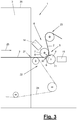
- FIG. 3 and 4th show the heat treatment device (1).
- the heating device (3) is designed, for example, as an oven with a surrounding housing (26) and heats the web of material (2). This can be done with a hot gas, for example.
- the heating device (3) and / or the Embossing device (4) has a conveying device (22) for the preferably continuous conveying of the material web (2). Alternatively, the conveying movement can be discontinuous, in particular intermittent.
- the material web (2) is transported in the transport direction (25) and leaves the heating device (3) and the housing (26) through an outlet (27).
- the additional heating means (34) can also be designed as a furnace or, alternatively, as a radiant heater or in some other way.
- the conveyor device (22) can be constructed in several parts. In the furnace area, for example, it has a circulating and preferably continuously driven endless conveyor belt (24) on which the web of material (2) rests. In the area of the embossing device (4), the conveying device (22) has a web guide (23) with several and at least partially driven deflection and drive rollers for the web of material (2).
- the embossing device (4) has an embossing tool (5) for carrying out the embossing process on the moving material web (2).
- plastic or permanent deformations are fluidically introduced into the material web (2). These are local and discrete deformations. They can be designed as impressions on the acted upon side, in particular the upper side, of the web of material (2).
- the embossments can also be perforated. Here, for example, through holes can be made locally in the end or crown area of the indentations formed as limited indentations.
- the embossing device (4) is provided and designed for a hot web of material (2).
- the embossing tool (5) can have a lower temperature than the hot material web (2).
- the embossing device (4) and the embossing tool (5) are attached to the web (2) and the web material, preferably fiber material, adapted.
- the stamping tool (5) stamps the web (2) with fluidic negative pressure and / or fluidic positive pressure.
- the stamping tool (5) stamps and, if necessary, perforates the material web (2) with a fluid flow (6) which is designed as a gas flow, in particular as an air flow.
- the embossing tool (5) has an embossing body (7) with a perforated body shell (9) on which the web of material (2) rests.
- the embossing body (7) can have any suitable shape, e.g. a cubic or parallelepiped shape.
- the embossing body (7) is designed as a rotating embossing roller with a perforated cylinder jacket (9).
- the web (2) emerges from the outlet (27) of the heating device (3) with a preferably straight extension and, for example, in a horizontal direction. It can be detached from the conveyor belt (24) after the outlet (27) and then arrives at or on the embossed body (7) following in the transport direction (25).
- the web of material (2) can rest against the shown rotating embossing roller (7) and be deflected over a larger angular range or wrap angle of, for example, approximately 90 ° or more.
- Figure 3 , 4th and 6th show different embodiments.
- the embossing tool has a counter body (8) which is arranged opposite the embossing body (7) transversely to the web of material (2).
- a gap is formed between the embossing body (7) and the counter body (8) through which the web of material (2) is guided.
- the contact point (32) can be designed as a contact surface or contact line, depending on the body geometry.
- the embossing body (7) can be arranged above or below the material web (2). This also applies if there is no counter body (8).
- a plurality of counter-bodies (8, 8 ') can be assigned to an embossing body (7).
- the counter body (8) also has a cylindrical shape and can be designed as a rotating counter roller. It can also have a perforated body shell (11).
- the counter body (8) can be designed as a hollow body. In a modification of the embodiment shown, the counter body (8) can have a different and, for example, cubic or parallelepiped-like shape.
- the contact point (32) or the gap is located, for example, approximately in the middle of the web wrap on the embossing roller (7).
- the counter roller (8) is arranged e.g. at an angle below the embossing roller (7).
- the rollers (7, 8) rotate in opposite directions and move circumferentially at the contact point (32) in the running direction (25) of the web (2).
- the rotationally symmetrical bodies (7, 8) can, for example, lie radially opposite one another.
- the body jackets (9, 11) of both bodies (7, 8) have a smooth wall or surface on the outside facing the material web (2) or the contact point (32).
- the embossing device (4) has a preferably controllable vacuum source (14) which is fluidically connected to the preferably hollow embossing body (7).
- the vacuum source (14) is designed, for example, as a suction device. From the vacuum source (14), a vacuum is applied to the perforation (10) of the body shell (9), which feeds the adjacent web material into the Perforation (10) sucks and is deformed like a bead in the process.
- the cavity formation can be present in the embossed body (7) or, if necessary, only in the body shell (9).
- the embossing device (4) also has a preferably controllable overpressure source (15) which directs a fluid flow (6) against the embossing body (7) and the material web (2) lying there.
- the fluid flow (6) can be designed differently, for example as a continuous curtain or in the form of discrete flow lines or fluid jets.
- the overpressure source (15) is designed, for example, as a blowing device which emits a gas flow, in particular an air flow.
- the fluid flow (6) can alternatively be formed by a liquid in the aforementioned manner.
- the negative pressure source (14) and the positive pressure source (15) can be arranged separately from one another and be independent of one another with regard to the fluid guidance and, if necessary, also the temperature control.
- Figure 3 shows such training.
- the negative pressure source (14) and the positive pressure source (15) can be fluidically connected to one another by a fluid return (18).
- the fluid flow (6) is thereby circulated in an essentially closed circuit.
- the negative pressure source (14) and the positive pressure source (15) can also be connected to form a circulation device (16).
- You can form a structural and device-related unit, for example in the form of a blower or ventilator with suction and discharge side.
- the fluid flow (6) has a lower temperature than the material web (2) acted upon. It has, for example, the external ambient temperature outside the heating device (3) or can be cooled with a cooler, for example a heat exchanger.
- the lower temperature is advantageous for the formation and subsequent consolidation of the mentioned web deformations at the perforation (10) of the embossing body (7).
- the fluid flow (6) directed against the perforation (10) can support the deformation of the material web area lying there. For this purpose, it can have a relatively large flow cross-section.
- the embossing device (4) can also have a cooling device (20) for the embossing tool (5).
- This can be, for example, air or water cooling, with which the embossed body (7) and / or the counter body (8), in particular their respective body shell (9, 11), is cooled.
- the cooling device (20) can be present in addition to the possibly existing cooling of the fluid flow (6).
- the embossing device (4) can have a fluid preparation (19) for the supplied or circulated fluid flow (6).
- the fluid treatment (19) can, for example, filter or otherwise purify the supplied or circulated fluid flow (6). If necessary, it can also take care of their conditioning, in particular cooling, dehumidification or the like.
- the overpressure source (15), in particular the blowing device, is fluidically connected, for example, to a nozzle (17) directed towards the embossing body (7) and the material web (2) lying there.
- the nozzle (17) is preferably arranged stationary in the hollow counter-body (8) and is directed on the outlet side against the contact point (32) of the embossed body (7), counter-body (8) and material web (2).
- the nozzle (17) emits the said fluid flow (6) through the perforation (12) of the counter body (8) and the material web (2) as well as the perforation (10) of the embossing body (7).
- the nozzle (17) with its mouth opening is preferably directed radially against the body shell (11) of the counter roller (8).
- the mouth opening can be designed in any suitable manner. It can also be adapted to the perforation (s) (10, 12). It can, for example, be designed as a continuous slot or as a series of discrete small point-like or slot-like mouth openings. The mouth opening can be present individually or several times.
- the perforation (10, 12) of the embossing body (7) and of the counter body (8) can be matched to one another. They have one or more passage openings in the body shell (9, 11) for the fluid flow (6). They can also have a similar opening distribution for the passage of the fluid flow (6) and be arranged in alignment. For the passage of the fluid flow (6), the openings of the perforations (10, 12) in the case of the preferably synchronously rotating rollers (7, 8) at the contact point (32) each come into congruence.
- FIG Figure 4 be larger than the openings of the perforation (12) of the counter body (8).
- the openings of the holes (10, 12) are the same size.
- the size ratios of the openings in the perforations (10, 12) can be varied and adapted to achieve the desired deformation or perforation.
- the size and shape of the openings in the perforation (10) on the embossing side determine the shape of the plastic web deformations generated during the embossing process.
- the shape can be arbitrary, for example punctiform with circular, oval or primatic outer contour or rod-shaped or cross-shaped or in wave shape etc ..
- the material web is pressed into the openings of the perforation (10) by the negative pressure and / or the positive pressure or blowing pressure and is deformed like a bead in the process.
- the fluid flow (6) can also flow through the deformed material web areas in the aforementioned manner and, if necessary, perforate them.
- Figure 5 shows this arrangement of embossing body (7), counter body (8) and a material web (2) located between them at the contact point (32).
- Figure 5 also illustrates on the left-hand side the formation of the bead-like deformation of the material web (2) by the fluid flow (6) in an opening of the perforation (10) of the embossing body (7). In the case of the other openings, this deformation is not shown for the sake of clarity.
- Figure 5 also shows a pairing and design of embossing and counter-bodies (7, 8) and their perforations (10, 12), which are primarily intended for embossing bead-like deformations.
- the perforation (10) of the embossing body (7) and possibly the perforation (12) of the counter body (8) can be arranged and designed to form a desired embossing pattern.
- the perforations (10, 12) can in particular consist of a uniform or non-uniform matrix of the perforation openings.
- the perforation openings are arranged distributed flat over the respective body casing (9, 11).
- the distribution can, for example, according to Figure 4 and 5 be uniform, with a plurality of axial rows of holes extending over the entire body length being distributed evenly over the body or cylinder circumference. In another embodiment, the rows of holes can only extend over a partial area of the body length or, if necessary, can also be interrupted.
- perforation openings can be arranged in a different pattern and a different distribution, which is possibly only arranged locally on the body shell and surrounded by solid shell areas.
- Such local clusters of perforated openings can be arranged several times over the body shell with a uniaxial or multi-axis offset, for example with an offset in the axial and circumferential direction of the rollers (7, 8).
- the perforation design can also be changed if necessary.
- the respective formation of the perforation arrangement can serve both deformation and solidification purposes, as well as decorative purposes.
- the embossed body (7) and the counter body (8) can have a common or synchronized drive technology (13) for their movement, in particular rotation.
- the drive technology (13) and the contact or clamping contact By means of the drive technology (13) and the contact or clamping contact, the material web (2) is on the one hand driven and moved on.
- the aforementioned aligned arrangement of the perforations (10, 12) at the point of passage of the fluid flow (6) is ensured.
- the drive technology (13) can have one or more drives, in particular rotary drives.
- a suitable controller (not shown) can be present to control the drive technology (13) or its drive (s).
- the other components of the embossing device (4), in particular the overpressure and / or underpressure source (14, 15), can also be connected to this control.
- the nozzle (17) locally directs a defined fluid flow (6) against the perforated body shell (11) of the preferably rotating counter body (8). From the openings of the perforation (12) emerge discrete and each directed towards an opening of the perforation (10). Ambient air can also be drawn in through a negative pressure in the embossing body (7) or its body shell (9) will.
- the negative pressure in the embossing body (7) creates a bead-like deformation in its perforation (10), which can be additionally perforated with a sharp fluid flow (6) from the nozzle (17).
- the bead-like deformation is smaller or flatter than in the case of a larger perforation (12) according to FIG Figure 5 .
- the ambient air can be sucked in through the gap at the contact point (32) and / or from a hollow counter body (8) through its perforation (12). Sucking in of ambient air outside the contact area (32) of the bodies or rollers (7, 8) can be prevented, for example by appropriately covering the perforation (s) (10, 12) of the embossing body (7) and / or the counter body ( 8th) .
- the same effect can be achieved by a diaphragm (35) arranged in the hollow mating body (8) which only has a local diaphragm opening at the said contact point (32) of the bodies (7, 8) or the passage point of the fluid flow (6). having.
- the overpressure source (15) can build up an overpressure in the entire hollow interior of the counter body (7) or an optionally multi-layer and hollow body shell (11).
- the counter body (7) can be omitted, only the nozzle (17) being present. It is also possible to provide only one positive pressure source (15) or only one negative pressure source (14). In the latter case, the negative pressure in the embossing body (7) or its body shell (9) can primarily suck in ambient air.
- the overpressure device (15), in particular its nozzle (17), can emit a sharp and preferably jet-like fluid flow (6).
- the same can be achieved with a corresponding design of an opening in the diaphragm (35).
- the discrete jets of fluid directed towards an opening in the perforation (10) have a very small diameter and can have a particularly high speed. This can be achieved by a particularly small opening diameter of the perforation (12) of the counter body (8) and / or by a corresponding mouth design of the nozzle (17) or the diaphragm (35).
- the fluid jets aim against the central area of the openings of the perforation (10) on the embossing element (7), which are substantially larger, e.g. by a factor of 10, and the local deformation of the web of material (2), which is mainly generated there by negative pressure and possibly cooled and solidified by ambient air. .
- the sharp fluid flow (6) or the fluid jets can perforate the deformation areas affected.
- the sharp fluid flow (6) or the fluid jets can act like a jet knife. For this purpose, it is advantageous to act on the web (2) in the central area of the wrap around the embossing body (7).
- a different shape and arrangement of the counter body (8) is possible, which is designed, for example, as an embossing roller with preferably radial pin-like or needle-like projections with a coordinated number and distribution.
- the components of the embossing tool (5) are each available individually. Alternatively, multiple arrangements are possible. In particular, several nozzles (17) can be arranged in the counter body (8) or free-standing.
- the embossing device (4) can have an adjusting device (21) for the delivery of the embossing tool (5) to the material web (2).
- an adjusting device (21) for the delivery of the embossing tool (5) to the material web (2).
- the embossing body (7) and / or the counter body (8) can be adjusted as required.
- the controllable actuating devices (21) are in Figure 4 indicated schematically by arrows.
- the embossing device (4) is arranged in the transport direction (25) of the moving web (2) behind the heating device (3). It is located near the outlet (27). In the illustrated and preferred exemplary embodiments, the embossing device (4) is arranged directly behind the heating device (3).
- the embossing device (4) is preferably built onto the heating device (3) and its housing (26). The web (2) emerging from the outlet (27) thus runs directly into the embossing device (4). The web of material (2) does not or only insignificantly cools on this short path.
- the embossing device (4) forms a consolidation device for the material web (2).
- the material web (2) is mechanically stabilized and solidified in the manner mentioned at the beginning by the mechanical impressions and / or perforations.
- the mechanical strength in particular the tensile strength in the running direction, is so great that the material web (2) guided over deflection and drive rollers of the web guide (23) and can be driven with a clamping fit or, if necessary, with a corresponding roller design, with a form fit.
- the embossing device (4) and / or the heat treatment device (1) can be an in Figure 3 have indicated detection device (32) for one or more process parameters. This can be, for example, the temperature of the material web (2) and / or of the embossing tool (5). Furthermore, the path and / or tool speed, the path structure, etc. can be detected.
- the detection device (32) can have one or more suitable sensors or the like. Detection means, e.g. a temperature sensor, a thermal imaging camera or the like the embossing device (4) are connected. A connection option can also exist for the other components of the heat treatment device (1) or the entire system.
- the controller controls and regulates the embossing process and, if necessary, other processes or devices.
- Figure 6 shows a variant of the embossing device (4) or of the embossing tool (5), in which two or more counter-rollers (8, 8 ') are assigned to an embossing roller (7).
- the counter-rollers (8, 8 ') are arranged one behind the other in the running direction of the web (2) and on the circumference of the embossing roller (7).
- the counter rollers (8, 8 ') can have different perforations (12, 12').
- the size and distribution of the openings in the perforation (12) of a counter-roller (8) can, for example, in the above-described and in Figure 5
- the manner shown correspond to the perforation (10) of the embossing body (7).
- the openings of the perforation (12 ') of the opposing roller following in the direction of web travel (8 ') are smaller than the openings in the perforation (10) of the embossing roller (7).
- the small openings in the perforation (12) are arranged at the contact point (32) in an overlap, preferably in a central congruence, opposite the openings in the perforation (10).
- the small openings and / or a nozzle (17) (not shown) each emit a sharp fluid jet which penetrates and perforates the respectively assigned and already existing deformation of the web of material (2).
- Figure 6 also shows the stationary arrangement of a diaphragm (35) instead of a nozzle (17) on the counter roller (8).
- the counter rollers (8, 8 ') are in Figure 6 connected to a circulating device (16) and are jointly supplied with a fluid, in particular air, which is preferably supplied under pressure and moved in a circuit.
- the supplied fluids can, as in Figure 6 shown, conditioned in the same way, in particular tempered.
- the fluid fed to the counter roller (8 ') for perforation can have a higher temperature.
- the counter rollers (8, 8 ') each have their own overpressure source (15) assigned to them.
- a hollow rotating counter roll (8, 8 ') Fluid supply with overpressure via a blowing device and, in addition, a supply of ambient air is possible.
- the embossing device (4) has a single embossing tool (5).
- the embossing body (7) in particular the embossing roller, is covered or wrapped around in some areas by the web (2). Alternatively, a tangential alignment is possible.
- the embossing body (7) and possibly the counter body (8) do not have to be part of the web guide (23). They can also have a body shell (9, 11) that is shaped differently, in particular flat, in the contact area. They can be fed to the web (2), in particular a flat web area, for embossing in cycles and removed again.
- the web (2) can be moved discontinuously in this and in other cases. It is also possible to switch the negative pressure source (14) and / or the positive pressure source (15) and let them act intermittently.
- embossing device (4) it is also possible to design the embossing device (4) as an independent and separate structural unit. It can also be spaced further from the heating device (3) in the transport direction (25) of the material web (2) than in the exemplary embodiments shown.
- the conveyor device (22) is adapted accordingly for this.
- the distance from the heating device (3) can be selected to be just large enough that no heat loss occurs in the material web (2) which is detrimental to the embossing process. Thermal insulation can avoid or minimize heat losses from the web (2) and enable greater distances.
- further machine parts or components can optionally also be arranged, which subject the web of material (2) to an additional treatment.
- a single material web (2) runs through the heating device (3) and the embossing device (4).
- a multiple arrangement of material webs (2) is possible.
- several webs of material (2) can be transported separately from one another through the heating device (3) and brought together at the embossing device (3) for a common embossing process.
- the material web (2) has a cohesive, mat-like structure, the width of which is greater than the thickness. Before entering the embossing device (3), it can have an essentially flat and homogeneous surface on one broad side.
- the web of material (2) can alternatively consist of individual parallel Strands are formed.
- the claimed embossing technology and, if applicable, the heat treatment technology are also suitable, with appropriate adaptation, for webs (2) made of a different material, for example a strip or foil made of metal, plastic or the like.
Landscapes
- Engineering & Computer Science (AREA)
- Mechanical Engineering (AREA)
- Textile Engineering (AREA)
- Treatment Of Fiber Materials (AREA)
- Machines For Manufacturing Corrugated Board In Mechanical Paper-Making Processes (AREA)
Description
- Die Erfindung betrifft eine Prägeeinrichtung und Prägeverfahren mit den Merkmalen in den unabhängigen Ansprüchen 1 und 14.
- Die
WO 2012/127013 A zeigt eine thermische Verfestigungseinrichtung und ein thermisches Verfestigungsverfahren für eine Vliesbahn in einem beheizten Thermobond-Ofen. Die Vliesbahn ist über eine rotierende luftdurchlässige Durchströmtrommel geführt, auf deren Außenumfang eine prägende Strukturschale mit Durchlassöffnungen angeordnet ist, die größer als die Trommelöffnungen sind. Heiße Ofenluft strömt durch die Öffnungen und schmilzt sowie verfestigt die Vliesfasern, wobei die Vliesbahn auch eine Prägung erhält. - Die
WO 03/023106 A2 WO 2005/124001 A1 zeigen Wasserstrahlverfestigungseinrichtungen. - Aus der Praxis sind Prägeeinrichtungen mit Prägewalzen bekannt, die auf eine abgekühlte Warenbahn aus einem textilen Fasermaterial, insbesondere ein Nonwoven-Faservlies einwirken. Diese Prägewalzen sind beheizt.
- Es ist Aufgabe der vorliegenden Erfindung, eine verbesserte Prägetechnik aufzuzeigen.
- Die Erfindung löst diese Aufgabe mit den Merkmalen in den unabhängigen Ansprüchen 1 und 14.
- Mit der beanspruchten Prägetechnik, d.h. der Prägeeinrichtung und dem Prägeverfahren, kann eine höhere Effizienz hinsichtlich Funktion und Qualität des Prägevorgangs sowie Bau- und Energieaufwand erreicht werden. Das Prägen kann zu unterschiedlichen Zwecken durchgeführt werden, z.B. zum Verfestigen und ggf. auch Perforieren der Warenbahn oder zu Dekorationszwecken. Die Warenbahn besteht bevorzugt aus einem textilen Fasermaterial, das z.B. ein Nonwoven-Faservlies sein kann.
- Bei der beanspruchten Prägetechnik wird die Warenbahn von einem Prägewerkzeug mit fluidischem Unterdruck und/oder fluidischem Überdruck geprägt. Die Warenbahn wird mit einer Gasströmung, geprägt und ggf. auch perforiert. Das Prägewerkzeug weist hierfür einen Prägekörper mit einem gelochten Korpusmantel auf, an dem die Warenbahn anliegt. Der fluidische Druck kann hierbei von der Innenseite des Prägekörpers und/oder von außen her wirken. Der fluidische Druck bzw. die Fluidströmung bewegt den beaufschlagten Warenbahnbereich in das darunter liegende Durchgangsloch des Korpusmantels und verformt diesen Warenbahnbereich dabei plastisch und dauerhaft unter Bildung eines lokalen Wulstes oder einer Kalotte. Die Wölbungsrichtung der Verformung und die Fluidströmung sind gleich gerichtet.
- Die zur fluidischen Prägung eingesetzte Gasströmung weist eine niedrigere Temperatur als die beaufschlagte Warenbahn, insbesondere der druckbeaufschlagte oder durchströmte Warenbahnbereich, auf. Diese Temperaturdifferenz ist günstig für die Ausbildung und Verfestigung der lokalen Verformung.
- Eine scharfe, insbesondere strahlartige, Fluidströmung ist für eine Perforation der z.B. bereits durch Unterdruck am Prägekörper erzeugten und in der dortigen Lochung befindlichen lokalen Verformungen der Warenbahn besonders günstig. Insbesondere kann eine Düse oder Blendenöffnung der Überdruckeinrichtung eine dünne, vorzugsweise heiße, Fluidströmung emittieren, die einen ggf. bereits verformten Bereich der Warenbahn perforiert.
- Der Prägekörper kann eine beliebige geeignete Formgebung haben und ist vorzugsweise als rotierende Prägewalze ausgebildet. An der Lochung des Korpusmantels wird das Warenbahnmaterial lokal in den Innenraum des Prägekörpers bzw. des Korpusmantels hineingezogen und dabei verformt und verfestigt. Der gelochte Korpusmantel ist an der zur Warenbahn gerichteten Außenseite vorzugsweise glattwandig ausgebildet.
- In einer einfachen Ausführungsform kann ein am Prägekörper angelegter Unterdruck aus einer bevorzugt steuerbaren Unterdruckquelle, insbesondere einer Saugeinrichtung, genügen. In einer anderen Ausführungsform kann zusätzlich ein an der gegenüberliegenden Warenbahnseite bzw. Außenseite wirkender Überdruck von einer bevorzugt steuerbaren Überdruckquelle, insbesondere einer Blaseinrichtung, einwirken. Hierdurch kann eine Gasströmung, gegen den Prägekörper und die dort anliegende Warenbahn gerichtet werden, welche die besagte Verformung der Warenbahn in der Lochung des Prägekörpers bewirkt oder unterstützt. In einer weiteren Abwandlung kann nur ein solcher Überdruck bzw. eine Überdruckquelle, insbesondere Blaseinrichtung, vorhanden sein.
- Ferner ist der Einsatz eines Gegenkörpers vorteilhaft, der an der freien Außenseite der Warenbahn anliegt, so dass die Warenbahn zwischen dem Prägekörper und dem Gegenkörper an einer Kontaktstelle gehalten und ggf. eingespannt werden kann. Der Gegenkörper kann außenseitig glattwandig ausgebildet sein. Er kann ebenfalls eine Lochung aufweisen, die an die Lochung des Prägekörpers adaptiert ist. Dies erlaubt die Erzeugung und Richtung einer Fluidströmung aus dem Gegenkörper durch die Warenbahn in den Prägekörper. Dies kann für eine besonders günstige und dauerhafte Verformung der Warenbahn sorgen.
- Ein Gegenkörper ist auch für eine gezielte Temperaturbeeinflussung der Warenbahn an der Kontaktstelle und/oder für eine Temperierung der Fluidströmung von Vorteil.
- Die Unterdruck- und/oder Überdruckquelle können separat angeordnet oder ggf. auch zu einer Umwälzeinrichtung verbunden sein. Die besagte Fluidströmung kann dabei im Kreislauf geführt und ggf. auch aufbereitet werden. Die Fluidströmung kann bedarfsweise konditioniert werden, z.B. hinsichtlich Temperatur und/oder Feuchte. Ferner ist es möglich, in den Gegenkörper zusätzlich oder alternativ Umgebungsluft zuzuführen.
- Dem Prägekörper können ein oder mehrere Gegenkörper zugeordnet werden. Bei einer Mehrfachanordnung können die Gegenkörper gleich oder unterschiedlich ausgebildet sein. Sie können z.B. eine unterschiedliche Lochung, insbesondere unterschiedliche Lochgrößen, aufweisen. Sie können auch ohne oder mit einer Blaseinrichtung, insbesondere zum Perforieren, ausgerüstet sein.
- Mit der Lochung des Prägekörpers und ggf. der Lochung des Gegenkörpers kann ein gewünschtes Prägemuster in der Warenbahn erzeugt werden. Hierdurch lassen sich außer der Verfestigung der Warenbahn auch dekorative oder andere Effekte erzielen. Zudem lässt sich durch eine Lochungsabstimmung die Form und Größe einer fluidischen Verformung, insbesondere Prägung, der Warenbahn beeinflussen und einstellen.
- Die beanspruchte Prägetechnik wird außerhalb einer Heizeinrichtung, insbesondere eines Ofens, zur Thermoverfestigung der Warenbahn durchgeführt. Das Prägen außerhalb und im nahen Anschluss an die Heizeinrichtung hat den Vorteil, dass die in der Warenbahn vorhandene Wärme und Temperatur genutzt werden kann, um eine plastische und dauerhafte Verformung der Warenbahn und des enthaltenen Fasermaterials beim Prägen zu erreichen. Hierbei kann eine Temperaturdifferenz zwischen der Warenbahn und dem Prägewerkzeug von Vorteil sein. Mit einer Kühleinrichtung für das Prägewerkzeug kann die Temperaturdifferenz optimiert sowie gesteuert und geregelt werden.
- Die beanspruchte Prägetechnik eignet sich besonders für eine kontinuierlich bewegte Warenbahn. Die Ausbildung des Prägewerkzeugs mit einem rotierenden und bevorzugt zylindrischen Prägekörper sowie ggf. einem entsprechend ausgebildeten, bevorzugt zylindrischen, Gegenkörper ist dabei von besonderem Vorteil. Ferner sind synchronisierte Antriebe für die besagten Präge- und Gegenkörper oder ein gemeinsamer Antrieb günstig.
- Die Prägeeinrichtung kann eine eigenständige Baueinheit darstellen, die einer Heizeinrichtung für die Warenbahn z.B. einem Thermobonding-Ofen, zugeordnet sein kann. Dies kann im Wege der Erstausrüstung oder Nachrüstung bzw. Umrüstung erfolgen. Eine Positioniereinrichtung ist für die räumliche Zuordnung vorteilhaft. Die Prägeeinrichtung kann auch mit der Heizeinrichtung zu einer Wärmebehandlungseinrichtung kombiniert werden.
- Die Prägeeinrichtung kann zur effizienten Ausnutzung der in der Warenbahn vorhandenen Wärmeenergie sehr nahe an der Heizeinrichtung angeordnet, insbesondere an dieser angebaut werden. Die enge Zuordnung von Heizeinrichtung und Prägeeinrichtung spart außer Energie auch Platz und Bauaufwand. Alternativ ist ein größerer Abstand zwischen Heizeinrichtung und Prägeeinrichtung möglich, wobei ein zusätzliches Heizmittel zwischengeschaltet sein kann. Eine Erfassungseinrichtung für Prozessparameter, insbesondere Temperatur(en), erlaubt eine optimale Steuerung des Prägeprozesses. An die Prägeeinrichtung kann sich eine Kühlstrecke beliebiger Art anschließen.
- Mit dem Prägeprozess kann die eingangs erwähnte Verfestigung der Warenbahn erreicht werden. Dies bringt auch Vorteile mit der Führung und dem Transport der Warenbahn mit sich. Die Warenbahn kann durch den unmittelbar an den Heizprozess anschließenden Prägeprozess schnell und wirksam mechanisch stabilisiert werden und lässt sich anschließend leichter und sicherer führen und transportieren. Unerwünschte Verformungen der Warenbahn auf Transportstrecken hinter der Heizeinrichtung können vermieden werden.
- Ein besonderer Vorteil der beanspruchten Prägetechnik liegt in der Möglichkeit zur Leistungssteigerung und zur Erhöhung der Geschwindigkeit der laufenden Warenbahn. Durch die bereits in der Warenbahn enthaltene Wärmeenergie genügt für den Prägeprozess eine räumlich und zeitlich kurze Beaufschlagung der Warenbahn mit dem Prägewerkzeug und dem fluidischen Unterdruck und/oder Überdruck. Die eingebrachten Verformungen in der Warenbahn werden durch ein thermisches Anhaften oder ein Verschmelzen der Fasern schnell fixiert. Hierfür ist die eingangs genannte Temperaturdifferenz zwischen Warenbahn und Fluidströmung und ggf. Prägewerkzeug besonders günstig. Die Fasern in der Warenbahn können dadurch ohne Anhaftgefahr von der Fluidströmung mitgenommen bzw. verformt und erst am Ende des Prägevorgangs fixiert werden. Außerdem wird Faserflug durch den Prägekörper und ggf. den Gegegenkörper verhindert, insbesondere wenn die Warenbahn bereits durch die Heizeinrichtung vorverfestigt und die enthaltenen Fasern gebunden sind.
- In den Unteransprüchen sind weitere vorteilhafte Ausgestaltungen der Erfindung angegeben.
- Die Erfindung ist in den Zeichnungen beispielhaft und schematisch dargestellt. Im Einzelnen zeigen:
- Figur 1:
- eine schematische Darstellung einer Faserbehandlungsanlage mit einer Prägeeinrichtung und einer Wärmebehandlungseinrichtung,
- Figur 2:
- eine Variante der Faserbehandlungsanlage von
Figur 1 , - Figur 3:
- eine abgebrochene Darstellung einer Prägeeinrichtung an einer Heizeinrichtung,
- Figur 4:
- eine ausschnittsweise und vergrößerte Darstellung der Prägeeinrichtung von
Figur 3 , - Figur 5:
- eine Variante einer Walzenpaarung und
- Figur 6:
- eine Variante der Prägeeinrichtung von
Figur 3 und4 . - Die Erfindung betrifft eine Prägeeinrichtung (4) und ein Prägeverfahren für eine Warenbahn (2). Die Erfindung betrifft ferner eine Wärmebehandlungseinrichtung (1), die von einer Prägeeinrichtung (4) und einer Heizeinrichtung (3) gebildet wird sowie ein Wärmebehandlungsverfahren. Schließlich betrifft die Erfindung auch eine Faserbehandlungsanlage (29) mit einer solchen Prägeeinrichtung (4) sowie ggf. auch einer Wärmebehandlungseinrichtung (1). Zur Erfindung gehört außerdem ein in der Faserbehandlungsanlage (29) durchgeführtes Behandlungsverfahren für Fasern.
- Die Warenbahn (2) besteht in den gezeigten Ausführungsbeispielen aus einem textilen Fasermaterial. Vorzugsweise handelt es sich um ein Nonwoven-Fasermaterial, z.B. ein Nonwoven-Faservlies. Das Fasermaterial besteht vorzugsweise aus kurzen geschnittenen Fasern. Die Fasern können Kunstfasern, insbesondere sogenannten BiCo-Fasern oder zweiKomponenten-Fasern, sein. Alternativ sind auch Naturfasern oder Fasergemische möglich.
-
Figur 1 und 2 zeigen Varianten einer Faserbehandlungsanlage (29) zur Herstellung und Verarbeitung einer solchen Warenbahn (2). In einem eingangsseitigen Florerzeuger (30), z.B. einer Karde oder Krempel oder einer Airlay-Maschine, wird ein einlagiger oder mehrlagiger Faserflor hergestellt, der die Warenbahn (2) im Frühstadium bildet. Der Faserflor wird anschließend einem Vliesleger (31), z.B. einem Kreuzbandleger, zugeführt und dort zu einem mehrlagigen Faservlies abgelegt. Dieses kann anschließend in einer Heizeinrichtung (3) termisch verfestigt werden. Dieser Prozess wird auch als Thermobonding bezeichnet. Die erhitzten Fasern in der Warenbahn (2) schmelzen zumindest partiell und haften aneinander oder verbinden sich miteinander. - Anschließend durchläuft die in Transportrichtung (25) bewegte heiße Warenbahn (2) eine Prägeeinrichtung (4), in der die Warenbahn (2) einem mechanischen Prägeprozess unterworfen wird, der mit fluidischen Unterdruck und/oder Überdruck in der nachfolgend beschriebenen Weise durchgeführt wird. Hierbei können Einprägungen in die Warenbahn (2) eingebracht werden. Die Warenbahn (2) kann auch perforiert werden. An die Prägeeinrichtung (4) kann sich eine Kühlstrecke (28) für die Warenbahn (2) anschließen. Ferner ist eine beliebige Weiterverarbeitung, insbesondere auch ein Zuschneiden, Aufwickeln, Bevorraten oder dgl. möglich.
- In der Variante von
Figur 1 ist die Prägeinrichtung (4) in unmittelbarer Nähe der Heizeinrichtung (3) angeordnet. Sie kann dabei direkt hinter der Heizeinrichtung (3) angeordnet oder an die Heizeinrichtung (3) angebaut sein. Bei der Variante vonFigur 2 ist eine größerer Abstand zwischen der Heizeinrichtung (3) und der Prägeinrichtung (4) vorhanden. Falls dies zu einer übermäßigen Abkühlung der Warenbahn (2) führen sollte, kann ein zusätzliches Heizmittel (34) im Zwischenraum angeordnet und der Prägeeinrichtung (4) vorgeschaltet sein. Alternativ oder zusätzlich können eine oder mehrere andere Maßnahmen zur Aufrechterhaltung der für den Prägeprozess vorteilhaften Warenbahntemperatur getroffen werden. - In
Figur 1 ist außerdem schematisch eine Positioniereinrichtung (33) für die Prägeeinrichtung (4) dargestellt. Damit lässt sich die Prägeeinrichtung (4) in einer oder mehreren Raumachsen, insbesondere in der Höhe und/oder im horizontalen Abstand verstellen und an die Heizeinrichtung (3) und ggf. die Lage der Warenbahn (2) anpassen. Die Positioniereinrichtung (33) kann auch bei den anderen Ausführungsbeispielen vorhanden sein. - Die Heizeinrichtung (3) und die Prägeinrichtung (4) können miteinander eine Wärmebehandlungseinrichtung (1) bilden. Die Prägeeinrichtung (4) kann dabei einen integralen Bestandteil der Wärmebehandlungseinrichtung (1) darstellen. Sie kann alternativ eine separate Baueinheit bilden.
-
Figur 3 und4 zeigen die Wärmebehandlungseinrichtung (1). Die Heizeinrichtung (3) ist z.B. als Ofen mit einem umgebenden Gehäuse (26) ausgebildet und heizt die Warenbahn (2) auf. Die kann z.B. mit einem Heißgas erfolgen. Die Heizeinrichtung (3) und/oder die Prägeeinrichtung (4) weist eine Fördereinrichtung (22) für die bevorzugt kontinuierliche Förderung der Warenbahn (2) auf. Alternativ kann die Förderbewegung diskontinuierlich, insbesondere intermittierend sein. Die Warenbahn (2) wird in Transportrichtung (25) transportiert und verlässt die Heizeinrichtung (3) und das Gehäuse (26) durch einen Auslauf (27). Das zusätzliche Heizmittel (34) kann ebenfalls als Ofen oder alternativ als Strahlungsheizung oder in anderer Weise ausgebildet sein. - Die Fördereinrichtung (22) kann mehrteilig ausgebildet sein. Sie weist z.B. im Ofenbereich ein umlaufend bewegtes und bevorzugt kontinuierlich angetriebenes endloses Transportband (24) auf, auf dem die Warenbahn (2) aufliegt. Im Bereich der Prägeeinrichtung (4) weist die Fördereinrichtung (22) eine Bahnführung (23) mit mehreren und zumindest teilweise angetriebenen Umlenk- und Treibrollen für die Warenbahn (2) auf.
- Die Prägeeinrichtung (4) weist ein Prägewerkzeug (5) zur Durchführung des Prägeprozesses an der laufenden Warenbahn (2) auf. Bei dem Prägeprozess werden auf fluidischem Weg plastische bzw. dauerhafte Verformungen in die Warenbahn (2) eingebracht. Dies sind lokale und diskrete Verformungen. Sie können als Einprägungen an der beaufschlagten Seite, insbesondere Oberseite, der Warenbahn (2) ausgebildet sein. Die Einprägungen können zudem perforiert sein. Hierbei können z.B. lokal Durchgangslöcher im End- oder Kuppenbereich der als begrenzte Vertiefungen ausgebildeten Einprägungen eingebracht werden.
- Die Prägeeinrichtung (4) ist für eine heiße Warenbahn (2) vorgesehen und ausgebildet. Das Prägewerkzeug (5) kann dabei eine niedrigere Temperatur als die heiße Warenbahn (2) haben. Die Prägeeinrichtung (4) und das Prägewerkzeug (5) sind an die Warenbahn (2) und das Bahnmaterial, vorzugsweise Fasermaterial, adaptiert.
- Das Prägewerkzeug (5) prägt die Warenbahn (2) mit fluidischem Unterdruck und/oder fluidischem Überdruck. Insbesondere prägt und ggf. perforiert das Prägewerkzeug (5) die Warenbahn (2) mit einer Fluidströmung (6), die als Gasströmung, insbesondere als Luftströmung ausgebildet ist.
- Das Prägewerkzeug (5) weist einen Prägekörper (7) mit einem gelochten Korpusmantel (9) auf, an dem die Warenbahn (2) anliegt. Der Prägekörper (7) kann eine beliebig geeignete Form, z.B. eine kubische bzw. quaderartige Form, aufweisen. In der gezeigten und bevorzugten Ausführungsform ist der Prägekörper (7) als rotierende Prägewalze mit einem gelochten Zylindermantel (9) ausgebildet.
- In der gezeigten Ausführungsform tritt die Warenbahn (2) aus dem Auslauf (27) der Heizeinrichtung (3) mit vorzugsweise gerader Erstreckung und z.B. in horizontaler Richtung aus. Sie kann nach dem Auslauf (27) vom Transportband (24) abgelöst werden und gelangt dann an oder auf den in Transportrichtung (25) folgenden Prägekörper (7). An der gezeigten rotierenden Prägewalze (7) kann die Warenbahn (2) dabei über einen größeren Winkelbereich bzw. Umschlingungswinkel von z.B. ca. 90° oder mehr anliegen und umgelenkt werden.
Figur 3 ,4 und6 zeigen verschiedene Ausführungsformen. - Das Prägewerkzeug weist in den gezeigten und bevorzugten Ausführungsformen einen Gegenkörper (8) auf, der dem Prägekörper (7) quer zur Warenbahn (2) gegenüberliegend angeordnet ist. Zwischen Prägekörper (7) und Gegenkörper (8) wird ein Spalt gebildet, durch den die Warenbahn (2) geführt ist. Hier kann eine Kontaktstelle (32) der Körper (7, 8) und der Warenbahn (2) gebildet werden, an der die Warenbahn (2) geführt und ggf. eingespannt sein kann. Die Kontaktstelle (32) kann je nach Körpergeometrie als Kontaktfläche oder Kontaktlinie ausgebildet sein. Der Prägekörper (7) kann oberhalb oder unterhalb der Warenbahn (2) angeordnet sein. Dies gilt auch, wenn kein Gegenkörper (8) vorhanden ist. Einem Prägekörper (7) können mehrere Gegenkörper (8, 8') zugeordnet sein.
- Der Gegenkörper (8) hat ebenfalls eine zylindrische Form und kann als rotierende Gegenwalze ausgebildet sein. Er kann ferner einen gelochten Korpusmantel (11) aufweisen. Der Gegenkörper (8) kann als Hohlkörper ausgebildet sein. In Abwandlung der gezeigten Ausführungsform kann der Gegenkörper (8) eine andere und z.B. kubische bzw. quaderartige Form aufweisen.
- Die Kontaktstelle (32) bzw. der Spalt befindet sich z.B. etwa in der Mitte der Bahnumschlingung an der Prägewalze (7). Die Gegenwalze (8) ist dabei z.B. schräg unterhalb der Prägewalze (7) angeordnet. Die Walzen (7,8) rotieren gegensinnig und bewegen sich umfangseitig an der Kontaktstelle (32) in Laufrichtung (25) der Warenbahn (2). Die rotationssymmetrischen Körper (7, 8) können einander z.B. radial gegenüber liegen. Die Korpusmäntel (9, 11) beider Körper (7, 8) weisen in den gezeigten Ausführungsformen an der zur Warenbahn (2) bzw. zur Kontaktstelle (32) gerichteten Außenseite eine glatte Wandung oder Oberfläche auf.
- Die Prägeeinrichtung (4) weist eine bevorzugt steuerbare Unterdruckquelle (14) auf, die mit dem bevorzugt hohlen Prägekörper (7) strömungstechnisch verbunden ist. Die Unterdruckquelle (14) ist z.B. als Saugeinrichtung ausgebildet. Von der Unterdruckquelle (14) wird ein Unterdruck an der Lochung (10) des Korpusmantels (9) angelegt, der das anliegende Warenbahnmaterial in die Lochung (10) saugt und dabei wulstartig verformt. Die Hohlraumausbildung kann im Prägekörper (7) oder ggf. nur im Korpusmantel (9) vorhanden sein.
- In der gezeigten Ausführungsform von
Figur 3 weist die Prägeeinrichtung (4) außerdem eine bevorzugt steuerbare Überdruckquelle (15) auf, die eine Fluidströmung (6) gegen den Prägekörper (7) und die dort anliegenden Warenbahn (2) richtet. Die Fluidströmung (6) kann unterschiedlich ausgebildet sein, z.B. als zusammenhängender Vorhang oder in Form von diskreten Strömungssträngen oder Fluidstrahlen. Die Überdruckquelle (15) ist z.B. als Blaseinrichtung ausgebildet, die eine Gasströmung, insbesondere eine Luftströmung, emittiert. Die Fluidströmung (6) kann alternativ in der vorerwähnten Weise von einer Flüssigkeit gebildet werden. - Die Unterdruckquelle (14) und die Überdruckquelle (15) können getrennt voneinander angeordnet und hinsichtlich der Fluidführung sowie ggf. auch der Temperierung unabhängig voneinander sein.
Figur 3 zeigt eine solche Ausbildung. - In der anderen Ausführungsform von
Figur 4 können die Unterdruckquelle (14) und die Überdruckquelle (15) durch eine Fluidrückführung (18) miteinander strömungstechnisch verbunden sein. Die Fluidströmung (6) wird dadurch in einem im Wesentlichen geschlossenen Kreislauf umgewälzt. Die Unterdruckquelle (14) und die Überdruckquelle (15) können auch zu einer Umwälzeinrichtung (16) verbunden sein. Sie können dabei eine bauliche und vorrichtungstechnische Einheit bilden, z.B. in Form eines Gebläses oder Ventilators mit Saug- und Blasseite. - Die Fluidströmung (6) weist eine niedrigere Temperatur als die beaufschlagte Warenbahn (2) auf. Sie hat z.B. die äußere Umgebungstemperatur außerhalb der Heizeinrichtung (3) oder kann mit einem Kühler, z.B. einem Wärmetauscher, gekühlt werden. Die niedrigere Temperatur ist zur Ausbildung und anschließende Verfestigung der erwähnten Warenbahnverformungen an der Lochung (10) des Prägekörpers (7) von Vorteil. Die gegen die Lochung (10) gerichtete Fluidströmung (6) kann die Verformung des dort anliegenden Warenbahnbereichs unterstützen. Sie kann hierfür einen relativ großen Strömungsquerschnitt aufweisen.
- Die Prägeeinrichtung (4) kann ferner eine Kühleinrichtung (20) für das Prägewerkzeug (5) aufweisen. Dies kann z.B. eine Luft- oder Wasserkühlung sein, mit der der Prägekörper (7) und/oder der Gegenkörper (8), insbesondere deren jeweiliger Korpusmantel (9, 11), gekühlt wird. Die Kühleinrichtung (20) kann zusätzlich zu der ggf. vorhandenen Kühlung der Fluidströmung (6) vorhanden sein.
- Die Prägeeinrichtung (4) kann eine Fluidaufbereitung (19) für die zugeführte oder umgewälzte Fluidströmung (6) aufweisen. Die Fluidaufbereitung (19) kann z.B. eine Filterung oder eine anderweitige Reinigung der zugeführten oder umgewälzten Fluidströmung (6) bewirken. Sie kann bedarfsweise auch für deren Konditionierung, insbesondere Kühlung, Entfeuchtung oder dgl. sorgen.
- Die Überdruckquelle (15), insbesondere die Blaseinrichtung, ist z.B. mit einer gegen den Prägkörper (7) und die dort anliegende Warenbahn (2) gerichteten Düse (17) strömungstechnisch verbunden. In den gezeigten Ausführungsbeispielen ist die Düse (17) im hohlen Gegenkörper (8) bevorzugt stationär angeordnet und ist auslassseitig gegen die Kontaktstelle (32) von Prägekörper (7), Gegenkörper (8) und Warenbahn (2) gerichtet.
- Die Düse (17) emittiert die besagte Fluidströmung (6) durch die Lochung (12) des Gegenkörpers (8) und die Warenbahn (2) sowie die Lochung (10) des Prägekörpers (7). Die Düse (17) ist hierfür mit ihrer Mündungsöffnung vorzugsweise radial gegen den Korpusmantel (11) der Gegenwalze (8) gerichtet. Die Mündungsöffnung kann in beliebig geeigneter Weise ausgebildet sein. Sie kann dabei auch an die Lochung(en) (10,12) angepasst sein. Sie kann z.B. als durchgehender Schlitz oder als Reihe von diskreten kleinen punktförmigen oder schlitzartigen Mündungsöffnungen gestaltet sein. Die Mündungsöffnung kann einzeln oder mehrfach vorhanden sein.
- Die Lochung (10,12) des Prägekörpers (7) und des Gegenkörpers (8) können aufeinander abgestimmt sein. Sie weisen eine oder mehrere Durchlassöffnungen im Korpusmantel (9, 11) für die Fluidströmung (6) auf. Sie können ferner für den Durchlass der Fluidströmung (6) eine gleichartige Öffnungsverteilung haben und fluchtend angeordnet sein. Für den Durchlass der Fluidströmung (6) kommen die Öffnungen der Lochungen (10, 12) bei den bevorzugt synchron rotierenden Walzen (7, 8) an der Kontaktstelle (32) jeweils zur Deckung.
- Die Öffnungen der Lochung (10) des Prägekörpers (7) können in der gezeigten Ausführungsform von
Figur 4 größer als die Öffnungen der Lochung (12) des Gegenkörpers (8) sein. In der Variante vonFigur 5 sind die Öffnungen der Lochungen (10, 12) gleich groß. Die Größenverhältnisse der Öffnungen der Lochungen (10, 12) können zur Erzielung der gewünschten Verformung bzw. Perforation variiert und angepasst werden. - Die Größe und Form der Öffnungen der prägeseitigen Lochung (10) bestimmen die Formgebung der beim Prägevorgang erzeugten plastischen Warenbahnverformungen. Die Formgebung kann beliebig sein, z.B. punktförmig mit kreisrunder, ovaler oder primatischer Außenkontur oder stabförmig oder kreuzförmig oder in Wellenform etc.. Durch den Unterdruck und/oder den Überdruck bzw. Blasdruck wird die Warenbahn in die Öffnungen der Lochung (10) hineingedrückt und dabei wulstartig verformt. Die Fluidströmung (6) kann dabei in der erwähnten Weise die verformten Warenbahnbereiche auch durchströmen und ggf. perforieren.
-
Figur 5 zeigt diese Anordnung von Prägekörper (7), Gegenkörper (8) und einer dazwischen an der Kontaktstelle (32) befindlichen Warenbahn (2).Figur 5 verdeutlicht außerdem an der linken Seite die Ausbildung der wulstartigen Verformung der Warenbahn (2) durch die Fluidströmung (6) in eine Öffnung der Lochung (10) des Prägekörpers (7). Bei den anderen Öffnungen ist diese Verformung der Übersicht halber nicht dargestellt. -
Figur 5 zeigt auch eine vornehmlich zum Prägen von wulstartigen Verformungen vorgesehene Paarung und Gestaltung von Präge- und Gegenkörper (7, 8) und deren Lochung (10, 12). - Die Lochung (10) des Prägekörpers (7) und ggf. die Lochung (12) des Gegenkörpers (8) können zur Ausbildung eines gewünschten Prägemusters angeordnet und ausgebildet sein. Die Lochungen (10, 12) können insbesondere aus einer gleichmäßigen oder ungleichmäßigen Matrix der Lochungsöffnungen bestehen. Die Lochungsöffnungen sind dabei flächig über den jeweiligen Korpusmantel (9, 11) verteilt angeordnet. Die Verteilung kann z.B. gemäß
Figur 4 und5 gleichmäßig sein, wobei mehrere axiale und über die gesamte Korpuslänge sich erstreckende Lochreihen gleichmäßig über den Korpus- bzw. Zylinderumfang verteilt angeordnet sind. In einer anderen Ausführung können die Lochreihen sich nur über einen Teilbereich der Korpuslänge erstrecken oder ggf. auch unterbrochen sein. Ferner können mehrere Lochungsöffnungen in einem anderen Muster und einer anderen Verteilung angeordnet sein, die ggf. nur lokal am Korpusmantel angeordnet und von massiven Mantelbereichen umgeben ist. Solche lokalen Cluster von Lochungsöffnungen können mehrfach über den Korpusmantel mit einem einachsigen oder mehrachsigen Versatz, z.B. mit Versatz in Axial- und Umfangsrichtung der Walzen (7, 8) angeordnet sein. Die Lochungsausbildung kann bedarfsweise auch geändert werden. Die jeweilige Ausbildung der Lochungsanordnung kann sowohl Verformungs- und Verfestigungszwecken, als auch dekorativen Zwecken dienen. - Der Prägekörper (7) und der Gegenkörper (8) können einen gemeinsame oder synchronisierte Antriebstechnik (13) für ihre Bewegung, insbesondere Rotation, aufweisen. Durch die Antriebstechnik (13) und den Anlage- oder Klemmkontakt wird einerseits die Warenbahn (2) angetrieben und weiterbewegt. Andererseits wird die vorerwähnt fluchtende Anordnung der Lochungen (10, 12) an der Durchtrittsstelle der Fluidströmung (6) sichergestellt.
- Die Antriebstechnik (13) kann einen oder mehrere Antriebe, insbesondere Drehantriebe, aufweisen. Zur Ansteuerung der Antriebstechnik (13) bzw. deren Antrieb(e) kann eine geeignete Steuerung (nicht dargestellt) vorhanden sein. An diese Steuerung können auch die anderen Komponenten der Prägeeineichtung (4), insbesondere die Überdruck- und/oder Unterdruckquelle (14, 15) angeschlossen sein.
- In den gezeigten Ausführungsformen von
Figur 3 und4 richtet die Düse (17) lokal eine definierte Fluidströmung (6) gegen den gelochten Korpusmantel (11) des bevorzugt rotierenden Gegenkörpers (8). Aus den Öffnungen der Lochung (12) treten dabei diskrete und jeweils gegen eine Öffnung der Lochung (10) gerichtete Strömungsstränge aus. Durch einen Unterdruck im Prägekörper (7) oder dessen Korpusmantel (9) kann außerdem Umgebungsluft angesaugt werden. - Der Unterdruck im Prägekörper (7) erzeugt eine wulstartige Verformung in dessen Lochung (10), die mit einer scharfen Fluidströmung (6) aus der Düse (17) zusätzlich perforiert werden kann. Bei einer Lochung (12) des Gegenkörpers (8) mit relativ kleinen Öffnungen ist die wulstartige Verformung kleiner bzw. flacher als bei einer größeren Lochung (12) gemäß
Figur 5 . - Die Umgebungsluft kann durch den Spalt an der Kontaktstelle (32) und/oder aus einem hohlen Gegenkörper (8) durch dessen Lochung (12) angesaugt werden. Ein Ansaugen von Umgebungsluft außerhalb des Kontaktbereichs (32) der Körper bzw. Walzen (7, 8) kann verhindert werden, z.B. durch eine entsprechende Abdeckung der Lochung(en) (10,12) des Prägekörpers (7) und/oder des Gegenkörpers (8) .
- In einer anderen und in
Figur 6 dargestellten Ausführungsform kann der gleiche Effekt durch eine im hohlen Gegenkörper (8) angeordnete Blende (35) erzielt werden, welche nur eine lokale Blendenöffnung an der besagten Kontaktstelle (32) der Körper (7, 8) bzw. der Durchtrittsstelle der Fluidströmung (6) aufweist. In diesem Fall kann die Überdruckquelle (15) einen Überdruck im gesamten hohlen Innenraum des Gegenkörpers (7) oder eines ggf. mehrlagigen und hohlen Korpusmantels (11) aufbauen. - In einer weiteren Ausführungsvariante kann der Gegenkörper (7) entfallen, wobei nur die Düse (17) vorhanden ist. Ferner ist es möglich, nur eine Überdruckquelle (15) oder nur eine Unterdruckquelle (14) vorzusehen. Im letztgenannten Fall kann durch den Unterdruck im Prägekörper (7) oder dessen Korpusmantel (9) vor allem Umgebungsluft angesaugt werden.
- In einer weiteren Ausführungsform gemäß
Figur 4 kann die Überdruckeinrichtung (15), insbesondere deren Düse (17), eine scharfe und bevorzugt strahlartige Fluidströmung (6) emittieren. Gleiches kann mit einer entsprechenden Gestaltung einer Öffnung der Blende (35) erreicht werden. - Die diskreten und jeweils gegen eine Öffnung der Lochung (10) gerichteten Fluidstrahlen haben einen sehr kleinen Durchmesser und können eine besonders hohe Geschwindigkeit haben. Dies kann durch einen besonders kleinen Öffnungsdurchmesser der Lochung (12) des Gegenkörpers (8) und/oder durch eine entsprechende Mündungsgestaltung der Düse (17) bzw. der Blende (35) erreicht werden.
- Die Fluidstrahlen zielen gegen den mittleren Bereich der wesentlich, z.B. um den Faktor 10, größeren Öffnungen der Lochung (10) am Prägekörper (7) und die dortige vornehmlich durch Unterdruck erzeugte und ggf. durch Umgebungsluft abgekühlte und verfestigte lokale Verformung der Warenbahn (2). Die scharfe Fluidströmung (6) bzw. die Fluidstrahlen können die getroffenen Verformungsbereiche perforieren. Die scharfe Fluidströmung (6) bzw. die Fluidstrahlen können wie ein Strahlmesser wirken. Hierfür ist eine Beaufschlagung der Warenbahn (2) im mittleren Bereich der Umschlingung am Prägekörper (7) vorteilhaft.
- Außerdem ist in einer weiteren und nicht dargestellten Variante eine andere Form und Anordnung des Gegenkörpers (8) möglich, der z.B. als Prägewalze mit bevorzugt radialen stift- oder nadelartigen Vorsprüngen mit abgestimmter Zahl und Verteilung ausgebildet ist. Diese greifen in die Öffnungen der Lochung (10) und unterstützen mechanisch den fluidisch und durch Unterdruck am Prägekörper (7) bewirkten Verformungsvorgang und/oder bewirken eine Perforation der Verformungen.
- In den gezeigten Ausführungsbeispielen sind die Komponenten des Prägewerkzeugs (5) jeweils einzeln vorhanden. Alternativ sind Mehrfachanordnungen möglich. Insbesondere können auch mehrere Düsen (17) im Gegenkörper (8) oder freistehend angeordnet sein.
- Die Prägeeinrichtung (4) kann eine Stelleinrichtung (21) für die Zustellung des Prägewerkzeugs (5) an die Warenbahn (2) aufweisen. Hierdurch kann der Prägekörper (7) und/oder der Gegenkörper (8) bedarfsweise verstellt werden. Die steuerbaren Stelleinrichtungen (21) sind in
Figur 4 schematisch durch Pfeile angedeutet. - Wie
Figur 3 und4 verdeutlichen, ist die Prägeeinrichtung (4) in Transportrichtung (25) der bewegten Warenbahn (2) hinter der Heizeinrichtung (3) angeordnet. Sie befindet sich dabei nahe am Auslauf (27). In den gezeigten und bevorzugten Ausführungsbeispielen ist die Prägeeinrichtung (4) direkt hinter der Heizeinrichtung (3) angeordnet. Vorzugsweise ist dabei die Prägeeinrichtung (4) an die Heizeinrichtung (3) und deren Gehäuse (26) angebaut. Die aus dem Auslauf (27) austretende Warenbahn (2) läuft dadurch unmittelbar in die Prägeeinrichtung (4) ein. Die Warenbahn (2) kühlt auf diesem kurzen Weg nicht oder nur unwesentlich ab. - Die Prägeeinrichtung (4) bildet eine Verfestigungseinrichtung für die Warenbahn (2). Die Warenbahn (2) wird in der eingangs erwähnten Weise durch die mechanischen Einprägungen und/oder Perforationen mechanisch stabilisiert und verfestigt. In Transportrichtung (25) hinter dem Prägewerkzeug (5) ist die mechanische Festigkeit, insbesondere auch die Zugfestigkeit in Laufrichtung, so groß, dass die Warenbahn (2) über Umlenk- und Treibrollen der Bahnführung (23) geführt und mit Klemmschluss oder ggf. auch bei entsprechender Walzenausbildung mit Formschluss angetrieben werden kann.
- Die Prägeeinrichtung (4) und/oder die Wärmebehandlungseinrichtung (1) kann eine in
Figur 3 angedeutete Erfassungseinrichtung (32) für einen oder mehrere Prozessparameter aufweisen. Dies kann z.B. die Temperatur der Warenbahn (2) und/oder des Prägewerkzeugs (5) sein. Ferner kann die Bahn- und/oder Werkzeuggeschwindigkeit, die Bahnstruktur etc. detektiert werden. Die Erfassungseinrichtung (32) kann für die Parametererfassung einen oder mehrere geeignete Sensoren oder dgl. Erfassungsmittel aufweisen, z.B. einen Temperaturfühler, eine Wärmebildkamera oder dgl.. Ferner ist eine nicht dargestellte Steuerung vorhanden, an welche die Erfassungseinrichtung (32) und die anderen angetriebenen Komponenten der Prägeeinrichtung (4) angeschlossen sind. Eine Anschlussmöglichkeit kann auch für die weiteren Komponenten der Wärmebehandlungseinrichtung (1) bzw. der gesamten Anlage bestehen. Die Steuerung steuert und regelt den Prägeprozess und ggf. weitere Prozesse bzw. Vorrichtungen. -
Figur 6 zeigt eine Variante der Prägeeinrichtung (4) bzw. des Prägewerkzeugs (5), bei der einer Prägewalze (7) zwei oder mehr Gegenwalzen (8, 8') zugeordnet sind. Die Gegenwalzen (8, 8') sind dabei in Laufrichtung der Warenbahn (2) und am Umfang der Prägewalze (7) verteilt hintereinander angeordnet. Die Gegenwalzen (8, 8') können eine unterschiedliche Lochung (12, 12') aufweisen. Die Größe und Verteilung der Öffnungen der Lochung (12) der einen Gegenwalze (8) kann z.B. in der vorbeschriebenen und inFigur 5 gezeigten Weise der Lochung (10) des Prägekörpers (7) entsprechen. Die Öffnungen der Lochung (12') der in Bahnlaufrichtung nachfolgenden Gegenwalze (8') sind kleiner als die Öffnungen der Lochung (10) der Prägewalze (7). Sie können der Ausführungsform vonFigur 4 entsprechen. Die kleinen Öffnungen der Lochung (12) sind an der Kontaktstelle (32) jeweils in Überlappung, vorzugsweise in zentrischer Deckung, gegenüber den Öffnungen der Lochung (10) angeordnet. Die kleinen Öffnungen und/oder eine Düse (17) (nicht dargestellt) emittieren jeweils einen scharfen Fluidstrahl, der die jeweils zugeordnete und bereits vorhandene Verformung der Warenbahn (2) durchdringt und perforiert. -
Figur 6 zeigt auch die stationäre Anordnung einer Blende (35) statt einer Düse (17) an der Gegenwalze (8). Die Gegenwalzen (8, 8') sind inFigur 6 an eine Umwälzeinrichtung (16) angeschlossen und werden gemeinsam mit einem bevorzugt unter Druck zugeführten und im Kreislauf bewegten Fluid, insbesondere Luft, versorgt. - Die zugeführten Fluide können, wie in
Figur 6 dargestellt, gleichartig konditioniert, insbesondere temperiert sein. Alternativ kann das der Gegenwalze (8') für das Perforieren zugeführte Fluid eine höhere Temperatur aufweisen. - Ferner kann in Abwandlung zu
Figur 6 statt der Umwälzeinrichtung (16) den Gegenwalzen (8, 8') jeweils eine eigene Überdruckquelle (15) zugeordnet sein. In weiterer Abwandlung ist es möglich, auf eine gesondere Fluidzuführung oder eine eigene Überdruckquelle (15) für eine Gegenwalze (8) zu verzichten und die Fluidströmung (6) nur mit dem Unterdruck in der Prägewalze (7) zu erzeugen. In die Gegenwalze (8) wird dabei Umgebungsluft durch diesen Unterdruck eingesaugt. Zur Richtung und Kontrolle der Fluidströmung (6) ist es nützlich, die Umgebungsluft axial zuzuführen und die inFigur 6 gezeigte Blende (35) einzusetzen. In weiterer Variation ist in einer hohlen rotierende Gegenwalze(8, 8') eine Fluidzuführung mit Überdruck über eine Blaseinrichtung und zusätzlich eine Zuführung von Umgebungsluft möglich. - Ferner ist es möglich, die Anordnung von
Figur 6 auch auf andere z.B. kubische Formen von Präge- und Gegenkörpern (7, 8, 8') mit entsprechender Anpassung zu übertragen. Hierbei kann die Warenbahn (2) auch diskontinuierlich bewegt werden. - Abwandlungen der gezeigten und beschriebenen Ausführungsformen sind in verschiedener Weise möglich. Insbesondere können die Merkmale der Ausführungsbeispiele und ihrer Abwandlungen beliebig miteinander kombiniert, insbesondere auch vertauscht werden.
- In den gezeigten Ausführungsbeispielen weist die Prägeeinrichtung (4) ein einzelnes Prägewerkzeug (5) auf. Alternativ kann eine Mehrfachanordnung von Prägewerkzeugen (5) vorhanden sein.
- Der Prägekörper (7), insbesondere die Prägewalze, ist bereichsweise von der Warenbahn (2) bedeckt bzw. umschlungen. Alternativ ist eine tangentiale Ausrichtung möglich. Der Prägekörper (7) und ggf. der Gegenkörper (8) müssen nicht Bestandteil der Warenbahnführung (23) sein. Sie können ferner einen im Kontaktbereich anders geformten, insbesondere ebenen, Korpusmantel (9,11) aufweisen. Sie können an die Warenbahn (2), insbesondere einen ebenen Warenbahnbereich, zum Prägen taktweise zugestellt und wieder entfernt werden. Die Warenbahn (2) kann in diesem und in anderen Fällen diskontinuierlich bewegt werden. Es ist außerdem möglich, die Unterdruckquelle (14) und/oder die Überdruckquelle (15) zu schalten und intermittierend wirken zu lassen.
- Ferner ist es möglich, die Prägeeinrichtung (4) als eigenständige und separate Baueinheit auszubilden. Sie kann auch weiter als in den gezeigten Ausführungsbeispielen von der Heizeinrichtung (3) in Transportrichtung (25) der Warenbahn (2) distanziert werden. Die Fördereinrichtung (22) ist hierfür entsprechend angepasst.
- Bei einer eigenständigen Anordnung der Heizeinrichtung (34) kann der Abstand zur Heizeinrichtung (3) gerade so groß gewählt werden, dass kein für den Prägeprozess abträglicher Wärmeverlust in der Warenbahn (2) eintritt. Eine Wärmedämmung kann Wärmeverluste der Warenbahn (2) vermeiden oder minimieren und größere Abstände ermöglichen. Zwischen der Prägeeinrichtung (4) und der Heizeinrichtung (3) können in Abwandlung der Ausführungsbeispiele ggf. auch weitere Maschinenteile oder Komponenten angeordnet sein, welche die Warenbahn (2) einer Zusatzbehandlung unterziehen.
- In den gezeigten Ausführungsbeispielen durchläuft eine einzelne Warenbahn (2) die Heizeinrichtung (3) und die Prägeeinrichtung (4). In Abwandlung hierzu ist eine Mehrfachanordnung von Warenbahnen (2) möglich. Insbesondere können mehrere Warenbahnen (2) voneinander getrennt durch die Heizeinrichtung (3) transportiert und an der Prägeeinrichtung (3) für einen gemeinsamen Prägeprozess zusammengeführt werden. Ferner ist es möglich, eine Prägeeinrichtung (4) mehreren Heizeinrichtungen (3) zuzuordnen.
- Die Warenbahn (2) hat in den Ausführungsbeispielen eine zusammenhängende, mattenartige Struktur, wobei deren Breite größer als die Dicke ist. Sie kann vor Eintritt in die Prägeeinrichtung (3) eine im wesentlichen ebene und homogene Oberfläche an einer Breitseite haben. Die Warenbahn (2) kann alternativ von einzelnen parallelen Strängen gebildet werden. Die beanspruchte Prägetechnik sowie ggf. die Wärmebehandlungstechnik eignet sich in entsprechender Anpassung auch für Warenbahnen (2), die aus einem anderen Material, z.B. einem Band- oder Folien aus Metall, Kunststoff oder dgl. bestehen.
-
- 1
- Wärmebehandlungseinrichtung
- 2
- Warenbahn, Vlies
- 3
- Heizeinrichtung, Ofen
- 4
- Prägeeinrichtung, Verfestigungseinrichtung
- 5
- Prägewerkzeug
- 6
- Fluidströmung, Gasströmung
- 7
- Prägekörper, Prägewalze
- 8
- Gegenkörper, Gegenwalze
- 8'
- Gegenkörper, Gegenwalze
- 9
- Korpusmantel, Zylindermantel Prägewalze
- 10
- Lochung
- 11
- Korpusmantel, Zylindermantel Gegenwalze
- 12
- Lochung
- 12'
- Lochung
- 13
- Antrieb
- 14
- Unterdruckquelle, Saugeinrichtung
- 15
- Überdruckquelle, Blaseinrichtung
- 16
- Umwälzeinrichtung
- 17
- Düse, Blasdüse
- 18
- Fluidrückführung
- 19
- Fluidaufbereitung
- 20
- Kühleinrichtung
- 21
- Stelleinrichtung
- 22
- Fördereinrichtung
- 23
- Bahnführung
- 24
- Transportband
- 25
- Transportrichtung, Laufrichtung
- 26
- Gehäuse
- 27
- Auslauf
- 28
- Kühlstrecke
- 29
- Faserbehandlungsanlage
- 30
- Florzeuger, Karde
- 31
- Vliesleger
- 32
- Kontaktstelle
- 33
- Positioniereinrichtung
- 34
- Heizmittel
- 35
- Blende
Claims (15)
- Prägeeinrichtung für eine Warenbahn (2) aus einem textilen Fasermaterial, insbesondere ein Nonwoven-Faservlies, mit einem Prägewerkzeug (5) zum Prägen der Warenbahn (2), wobei das Prägewerkzeug (5) die Warenbahn (2) mit fluidischem Unterdruck und/oder fluidischem Überdruck prägt, wobei das Prägewerkzeug (5) die Warenbahn (2) mit einer Gasströmung (6) prägt und ggf. perforiert, und wobei die Gasströmung (6) eine niedrigere Temperatur als die beaufschlagte Warenbahn (2) aufweist.
- Prägeeinrichtung nach Anspruch 1, dadurch gekennzeichnet, dass das Prägewerkzeug (5) einen Prägekörper (7) mit einem gelochten Korpusmantel (9) aufweist, an dem die Warenbahn (2) anliegt, wobei der Korpusmantel (9) an der zur Warenbahn (2) weisenden Außenseite bevorzugt glattwandig ausgebildet ist und wobei der Prägekörper (7) bevorzugt als rotierende Prägewalze mit einem gelochten Zylindermantel (9) ausgebildet ist.
- Prägeeinrichtung nach Anspruch 1 oder 2, dadurch gekennzeichnet, dass die Prägeeinrichtung (4) eine bevorzugt steuerbare Unterdruckquelle (14), insbesondere eine Saugeinrichtung, aufweist, die mit dem bevorzugt hohlen Prägekörper (7) strömungstechnisch verbunden ist.
- Prägeeinrichtung nach einem der vorhergehenden Ansprüche, dadurch gekennzeichnet, dass die Prägeeinrichtung (4) eine bevorzugt steuerbare Überdruckquelle (15), insbesondere eine Blaseinrichtung, aufweist, die eine Gasströmung (6) gegen den Prägekörper (7) und die dort anliegende Warenbahn (2) richtet.
- Prägeeinrichtung nach einem der vorhergehenden Ansprüche, dadurch gekennzeichnet, dass das Prägewerkzeug (5) einen Gegenkörper (8) mit einem gelochten Korpusmantel (11), aufweist, der dem Prägekörper (7) quer zur Warenbahn (2) gegenüberliegend angeordnet ist.
- Prägeeinrichtung nach Anspruch 5, dadurch gekennzeichnet, dass die Überdruckquelle (15), insbesondere Blaseinrichtung, mit dem bevorzugt hohlen und insbesondere zylindrischen Gegenkörper (8) strömungstechnisch verbunden ist.
- Prägeeinrichtung nach Anspruch 5 oder 6, dadurch gekennzeichnet, dass die Überdruckquelle (15), insbesondere Blaseinrichtung, mit einer gegen den Prägekörper (7) und die dort anliegende Warenbahn (2) gerichteten Düse (17) oder Blende (35) strömungstechnisch verbunden ist, wobei die Düse (17) oder Blende (35) im Gegenkörper (8) bevorzugt stationär angeordnet ist.
- Prägeeinrichtung nach Anspruch 5, 6 oder 7, dadurch gekennzeichnet, dass die Düse (17) oder Blende (35) im Gegenkörper (8) auslassseitig gegen den gelochten Korpusmantel (11) und die Kontaktstelle (32) von Prägekörper (7), Gegenkörper (8) und Warenbahn (2) gerichtet ist und die Fluidströmung (6) durch die Lochung (12) des Gegenkörpers (8) emittiert, wobei die Lochung (10,12) des Prägekörpers (7) und des Gegenkörpers (8) aufeinander abgestimmt und für den Durchlass einer Fluidströmung (6), insbesondere Gasströmung, fluchtend angeordnet sind.
- Prägeeinrichtung nach einem der vorhergehenden Ansprüche, dadurch gekennzeichnet, dass die Düse (17) oder Blende (35) eine dünne Fluidströmung (6) emittiert, die einen ggf. verformten Bereich der Warenbahn (2) perforiert.
- Prägeeinrichtung nach einem der vorhergehenden Ansprüche, dadurch gekennzeichnet, dass die Prägeeinrichtung (4) für eine heiße Warenbahn (2) vorgesehen und ausgebildet ist, wobei das Prägewerkzeug (5) eine niedrigere Temperatur als die Warenbahn (2) aufweist.
- Wärmebehandlungseinrichtung für eine Warenbahn (2) aus einem textilen Fasermaterial, insbesondere ein Nonwoven-Faservlies, mit einer Heizeinrichtung (3) und einer Prägeeinrichtung (4) für die Warenbahn (2), dadurch gekennzeichnet, dass die Prägeeinrichtung (4) nach mindestens einem der Ansprüche 1 bis 10 ausgebildet ist, wobei die Prägeeinrichtung (4) in Transportrichtung (25) der bewegten Warenbahn (2) hinter der Heizeinrichtung (3), bevorzugt direkt hinter der Heizeinrichtung (3), angeordnet ist.
- Wärmebehandlungseinrichtung nach Anspruch 11,
dadurch gekennzeichnet, dass die Prägeeinrichtung (4) direkt hinter der Heizeinrichtung (3) angeordnet, insbesondere an die Heizeinrichtung (3) angebaut ist. - Faserbehandlungsanlage für eine Warenbahn (2) aus einem textilen Fasermaterial, insbesondere ein Nonwoven-Faservlies, mit einem Florerzeuger, insbesondere einer Karde oder Krempel, einem Vliesleger und einer Wärmebehandlungseinrichtung (1) für die Warenbahn (2), dadurch gekennzeichnet, dass die Wärmebehandlungseinrichtung (1) nach Anspruch 11 oder 12 ausgebildet ist.
- Verfahren zum Prägen einer Warenbahn (2) aus einem textilen Fasermaterial, insbesondere ein Nonwoven-Faservlies, mit einem Prägewerkzeug (5), wobei die Warenbahn (2) vom Prägewerkzeug (5) mit fluidischem Unterdruck und/oder fluidischem Überdruck geprägt wird, wobei das Prägewerkzeug (5) die Warenbahn (2) mit einer Gasströmung (6) prägt und ggf. perforiert und wobei die Gasströmung (6) eine niedrigere Temperatur als die beaufschlagte Warenbahn (2) aufweist.
- Verfahren nach Anspruch 14, dadurch gekennzeichnet, dass die Warenbahn (2) an einer Kontaktstelle (32) zwischen einem Prägekörper (7) mit einem gelochten Korpusmantel (9) und einem Gegenkörper (8) mit einem gelochten Korpusmantel (11) angeordnet ist.
Priority Applications (1)
| Application Number | Priority Date | Filing Date | Title |
|---|---|---|---|
| EP21212756.7A EP4001486B1 (de) | 2015-09-03 | 2016-09-03 | Prägeeinrichtung und prägeverfahren |
Applications Claiming Priority (2)
| Application Number | Priority Date | Filing Date | Title |
|---|---|---|---|
| DE202015104671.5U DE202015104671U1 (de) | 2015-09-03 | 2015-09-03 | Prägeeinrichtung |
| PCT/EP2016/070788 WO2017037273A1 (de) | 2015-09-03 | 2016-09-03 | Prägeeinrichtung |
Related Child Applications (2)
| Application Number | Title | Priority Date | Filing Date |
|---|---|---|---|
| EP21212756.7A Division EP4001486B1 (de) | 2015-09-03 | 2016-09-03 | Prägeeinrichtung und prägeverfahren |
| EP21212756.7A Division-Into EP4001486B1 (de) | 2015-09-03 | 2016-09-03 | Prägeeinrichtung und prägeverfahren |
Publications (3)
| Publication Number | Publication Date |
|---|---|
| EP3344810A1 EP3344810A1 (de) | 2018-07-11 |
| EP3344810B1 true EP3344810B1 (de) | 2021-12-08 |
| EP3344810B8 EP3344810B8 (de) | 2022-02-09 |
Family
ID=56943477
Family Applications (2)
| Application Number | Title | Priority Date | Filing Date |
|---|---|---|---|
| EP21212756.7A Active EP4001486B1 (de) | 2015-09-03 | 2016-09-03 | Prägeeinrichtung und prägeverfahren |
| EP16766871.4A Not-in-force EP3344810B8 (de) | 2015-09-03 | 2016-09-03 | Prägeeinrichtung |
Family Applications Before (1)
| Application Number | Title | Priority Date | Filing Date |
|---|---|---|---|
| EP21212756.7A Active EP4001486B1 (de) | 2015-09-03 | 2016-09-03 | Prägeeinrichtung und prägeverfahren |
Country Status (3)
| Country | Link |
|---|---|
| EP (2) | EP4001486B1 (de) |
| DE (1) | DE202015104671U1 (de) |
| WO (1) | WO2017037273A1 (de) |
Families Citing this family (2)
| Publication number | Priority date | Publication date | Assignee | Title |
|---|---|---|---|---|
| MX2022015935A (es) | 2020-07-03 | 2023-01-24 | Essity Hygiene & Health Ab | Rollos sin nucleo de un producto de papel tisu y metodos de fabricacion de rollos sin nucleo. |
| DE202023100465U1 (de) * | 2023-01-31 | 2024-05-06 | Autefa Solutions Germany Gmbh | Prägeeinrichtung |
Family Cites Families (13)
| Publication number | Priority date | Publication date | Assignee | Title |
|---|---|---|---|---|
| DE68915748T2 (de) | 1989-03-09 | 1994-09-22 | Perfojet Sa | Vorrichtung zum Perforieren eines blattartigen Produktes. |
| JP3171457B2 (ja) | 1991-04-26 | 2001-05-28 | 日本フイルコン株式会社 | 突起を設けた不織布製造用ベルト及び模様を形成した不織布の製造方法 |
| RU2105092C1 (ru) | 1992-02-18 | 1998-02-20 | МакНЕЙЛ-ППС, ИНК. | Нетканый материал (варианты), устройство для изготовления нетканого материала, устройство для изготовления перераспределенного нетканого материала, способ изготовления нетканого материала |
| DE19912279A1 (de) | 1999-03-18 | 2000-09-21 | Fleissner Maschf Gmbh Co | Verfahren und Vorrichtung zur Herstellung von Nonwovens mit Präge- oder Lochmuster mittels hydrodynamischer Vernadelung |
| US6572722B1 (en) * | 1999-11-22 | 2003-06-03 | The Procter & Gamble Company | Process for autogeneously bonding laminae of a mult-lamina cellulosic substrate |
| DE10132563A1 (de) | 2001-07-10 | 2003-01-30 | Fleissner Maschf Gmbh Co | Verfahren zur farblosen Musterung einer Warenbahn und Vorrichtung zur Durchführung des Verfahrens |
| AU2002339886A1 (en) * | 2001-09-07 | 2003-03-24 | Polymer Group, Inc. | Imaged nonwoven fabric comprising lyocell fibers |
| FI121182B (fi) * | 2004-06-18 | 2010-08-13 | Suominen Nonwovens Ltd | Menetelmä kuitukankaan valmistamiseksi |
| US20070256286A1 (en) | 2006-05-05 | 2007-11-08 | Pgi Polymer, Inc. | Method and apparatus for perforating a fibrous web |
| DE102007043543A1 (de) | 2007-09-12 | 2009-03-19 | Fleissner Gmbh | Verfahren und Vorrichtung zur Herstellung dreidimensional strukturierter Vliesstoffe |
| DE102007053030A1 (de) | 2007-11-05 | 2009-05-07 | Fleissner Gmbh | Einrichtung zur Beaufschlagung von Stoffen mittels heißen Gasen |
| DE102007053991A1 (de) | 2007-11-13 | 2009-05-14 | Fleissner Gmbh | Vorrichtung zur Beaufschlagung von Stoffen mittels heißen Gasen |
| DE202011004335U1 (de) * | 2011-03-23 | 2012-03-26 | Trützschler Nonwovens Gmbh | Einrichtung zur Verfestigung eines textilen Produktes mittels heißen Gasen |
-
2015
- 2015-09-03 DE DE202015104671.5U patent/DE202015104671U1/de not_active Expired - Lifetime
-
2016
- 2016-09-03 EP EP21212756.7A patent/EP4001486B1/de active Active
- 2016-09-03 WO PCT/EP2016/070788 patent/WO2017037273A1/de not_active Ceased
- 2016-09-03 EP EP16766871.4A patent/EP3344810B8/de not_active Not-in-force
Non-Patent Citations (1)
| Title |
|---|
| None * |
Also Published As
| Publication number | Publication date |
|---|---|
| EP3344810A1 (de) | 2018-07-11 |
| EP4001486C0 (de) | 2025-04-09 |
| EP4001486B1 (de) | 2025-04-09 |
| DE202015104671U1 (de) | 2016-12-06 |
| EP3344810B8 (de) | 2022-02-09 |
| WO2017037273A1 (de) | 2017-03-09 |
| EP4001486A1 (de) | 2022-05-25 |
Similar Documents
| Publication | Publication Date | Title |
|---|---|---|
| EP3011092B1 (de) | Kohlenstofffaser-wirrvliesherstellungsverfahren, -anordnung sowie dreidimensionalbauteil-vliesherstellungsverfahren | |
| TWI618830B (zh) | 熱風處理不織布加工裝置及加工方法 | |
| DE10232148B4 (de) | Verfahren zum flüssigkeitsdurchlässigen Perforieren eines Vlieses | |
| DE1785302C3 (de) | Verfahren und Vorrichtung zum kontinuierlichen Herstellen eines Wirrfadenvlieses und Wirrfadenvlies | |
| EP1155178B1 (de) | Verfahren und vorrichtung zur herstellung einer strukturierten, voluminösen vliesbahn oder folie | |
| DE60300540T4 (de) | Vorrichtung zur Herstellung eines gemusterten Textilproduktes und daraus hergestellter Vliesstoff | |
| EP0115804B1 (de) | Verfahren zum Herstellen einer Weichkunststoffolie | |
| EP2689060B1 (de) | EINRICHTUNG ZUR VERFESTIGUNG EINES TEXTILEN PRODUKTES MITTELS HEIßEN GASEN | |
| EP1825046B1 (de) | Musterung auf sms-produkt | |
| DE3016568A1 (de) | Verfahren und vorrichtung zum texturieren einer thermoplastischen folie | |
| RU2454376C2 (ru) | Способ изготовления пряди композиционного материала и устройство для его осуществления | |
| US20230330682A1 (en) | Discretizer and Method of Using Same | |
| JP4903866B2 (ja) | エアレイド吸収コアを形成するための装置および方法 | |
| EP4001486B1 (de) | Prägeeinrichtung und prägeverfahren | |
| DE4312309A1 (de) | Verfahren und Vorrichtungen zur Herstellung eines Spinnvlies-Flächenproduktes | |
| EP3526042B1 (de) | Vorrichtung zum kaschieren eines substrates mit einem thermoplastischen beschichtungsmaterial | |
| DE202016105337U1 (de) | Aerodynamische Vliesbildeeinrichtung | |
| DE602005002542T2 (de) | Übertragung von harz zum formen von befestigungselementen | |
| DE202014102656U1 (de) | Prägeeinrichtung | |
| DE102007043543A1 (de) | Verfahren und Vorrichtung zur Herstellung dreidimensional strukturierter Vliesstoffe | |
| DE202023100465U1 (de) | Prägeeinrichtung | |
| DE2628676C2 (de) | "Vorrichtung und Verfarhen zum kontinuierlichen Transferbedrucken von Textilbahnen" | |
| DE4333877A1 (de) | Verfahren und Vorrichtung zum Trennen von Geweben schmelzfähigen Materials | |
| DE19750459C2 (de) | Kalander zum Perforieren einer Bahn | |
| DE1809761A1 (de) | Verfahren und Vorrichtung zur kontinuierlichen Herstellung von Lunten,Garnen,Vliesen aus einem thermoplastischen Material |
Legal Events
| Date | Code | Title | Description |
|---|---|---|---|
| STAA | Information on the status of an ep patent application or granted ep patent |
Free format text: STATUS: THE INTERNATIONAL PUBLICATION HAS BEEN MADE |
|
| PUAI | Public reference made under article 153(3) epc to a published international application that has entered the european phase |
Free format text: ORIGINAL CODE: 0009012 |
|
| STAA | Information on the status of an ep patent application or granted ep patent |
Free format text: STATUS: REQUEST FOR EXAMINATION WAS MADE |
|
| 17P | Request for examination filed |
Effective date: 20180301 |
|
| AK | Designated contracting states |
Kind code of ref document: A1 Designated state(s): AL AT BE BG CH CY CZ DE DK EE ES FI FR GB GR HR HU IE IS IT LI LT LU LV MC MK MT NL NO PL PT RO RS SE SI SK SM TR |
|
| AX | Request for extension of the european patent |
Extension state: BA ME |
|
| DAV | Request for validation of the european patent (deleted) | ||
| DAX | Request for extension of the european patent (deleted) | ||
| STAA | Information on the status of an ep patent application or granted ep patent |
Free format text: STATUS: EXAMINATION IS IN PROGRESS |
|
| 17Q | First examination report despatched |
Effective date: 20200903 |
|
| GRAP | Despatch of communication of intention to grant a patent |
Free format text: ORIGINAL CODE: EPIDOSNIGR1 |
|
| STAA | Information on the status of an ep patent application or granted ep patent |
Free format text: STATUS: GRANT OF PATENT IS INTENDED |
|
| INTG | Intention to grant announced |
Effective date: 20210702 |
|
| GRAS | Grant fee paid |
Free format text: ORIGINAL CODE: EPIDOSNIGR3 |
|
| GRAA | (expected) grant |
Free format text: ORIGINAL CODE: 0009210 |
|
| STAA | Information on the status of an ep patent application or granted ep patent |
Free format text: STATUS: THE PATENT HAS BEEN GRANTED |
|
| AK | Designated contracting states |
Kind code of ref document: B1 Designated state(s): AL AT BE BG CH CY CZ DE DK EE ES FI FR GB GR HR HU IE IS IT LI LT LU LV MC MK MT NL NO PL PT RO RS SE SI SK SM TR |
|
| REG | Reference to a national code |
Ref country code: GB Ref legal event code: FG4D Free format text: NOT ENGLISH |
|
| REG | Reference to a national code |
Ref country code: AT Ref legal event code: REF Ref document number: 1453842 Country of ref document: AT Kind code of ref document: T Effective date: 20211215 Ref country code: CH Ref legal event code: EP |
|
| REG | Reference to a national code |
Ref country code: CH Ref legal event code: PK Free format text: BERICHTIGUNG PRIORITAET Ref country code: DE Ref legal event code: R096 Ref document number: 502016014252 Country of ref document: DE |
|
| REG | Reference to a national code |
Ref country code: IE Ref legal event code: FG4D Free format text: LANGUAGE OF EP DOCUMENT: GERMAN |
|
| REG | Reference to a national code |
Ref country code: CH Ref legal event code: PK Free format text: BERICHTIGUNG B8 |
|
| REG | Reference to a national code |
Ref country code: LT Ref legal event code: MG9D |
|
| REG | Reference to a national code |
Ref country code: NL Ref legal event code: MP Effective date: 20211208 |
|
| PG25 | Lapsed in a contracting state [announced via postgrant information from national office to epo] |
Ref country code: RS Free format text: LAPSE BECAUSE OF FAILURE TO SUBMIT A TRANSLATION OF THE DESCRIPTION OR TO PAY THE FEE WITHIN THE PRESCRIBED TIME-LIMIT Effective date: 20211208 Ref country code: LT Free format text: LAPSE BECAUSE OF FAILURE TO SUBMIT A TRANSLATION OF THE DESCRIPTION OR TO PAY THE FEE WITHIN THE PRESCRIBED TIME-LIMIT Effective date: 20211208 Ref country code: FI Free format text: LAPSE BECAUSE OF FAILURE TO SUBMIT A TRANSLATION OF THE DESCRIPTION OR TO PAY THE FEE WITHIN THE PRESCRIBED TIME-LIMIT Effective date: 20211208 Ref country code: BG Free format text: LAPSE BECAUSE OF FAILURE TO SUBMIT A TRANSLATION OF THE DESCRIPTION OR TO PAY THE FEE WITHIN THE PRESCRIBED TIME-LIMIT Effective date: 20220308 |
|
| PG25 | Lapsed in a contracting state [announced via postgrant information from national office to epo] |
Ref country code: SK Free format text: LAPSE BECAUSE OF FAILURE TO SUBMIT A TRANSLATION OF THE DESCRIPTION OR TO PAY THE FEE WITHIN THE PRESCRIBED TIME-LIMIT Effective date: 20211208 Ref country code: SE Free format text: LAPSE BECAUSE OF FAILURE TO SUBMIT A TRANSLATION OF THE DESCRIPTION OR TO PAY THE FEE WITHIN THE PRESCRIBED TIME-LIMIT Effective date: 20211208 Ref country code: NO Free format text: LAPSE BECAUSE OF FAILURE TO SUBMIT A TRANSLATION OF THE DESCRIPTION OR TO PAY THE FEE WITHIN THE PRESCRIBED TIME-LIMIT Effective date: 20220308 Ref country code: LV Free format text: LAPSE BECAUSE OF FAILURE TO SUBMIT A TRANSLATION OF THE DESCRIPTION OR TO PAY THE FEE WITHIN THE PRESCRIBED TIME-LIMIT Effective date: 20211208 Ref country code: HR Free format text: LAPSE BECAUSE OF FAILURE TO SUBMIT A TRANSLATION OF THE DESCRIPTION OR TO PAY THE FEE WITHIN THE PRESCRIBED TIME-LIMIT Effective date: 20211208 Ref country code: GR Free format text: LAPSE BECAUSE OF FAILURE TO SUBMIT A TRANSLATION OF THE DESCRIPTION OR TO PAY THE FEE WITHIN THE PRESCRIBED TIME-LIMIT Effective date: 20220309 Ref country code: ES Free format text: LAPSE BECAUSE OF FAILURE TO SUBMIT A TRANSLATION OF THE DESCRIPTION OR TO PAY THE FEE WITHIN THE PRESCRIBED TIME-LIMIT Effective date: 20211208 |
|
| PG25 | Lapsed in a contracting state [announced via postgrant information from national office to epo] |
Ref country code: NL Free format text: LAPSE BECAUSE OF FAILURE TO SUBMIT A TRANSLATION OF THE DESCRIPTION OR TO PAY THE FEE WITHIN THE PRESCRIBED TIME-LIMIT Effective date: 20211208 |
|
| PG25 | Lapsed in a contracting state [announced via postgrant information from national office to epo] |
Ref country code: SM Free format text: LAPSE BECAUSE OF FAILURE TO SUBMIT A TRANSLATION OF THE DESCRIPTION OR TO PAY THE FEE WITHIN THE PRESCRIBED TIME-LIMIT Effective date: 20211208 Ref country code: RO Free format text: LAPSE BECAUSE OF FAILURE TO SUBMIT A TRANSLATION OF THE DESCRIPTION OR TO PAY THE FEE WITHIN THE PRESCRIBED TIME-LIMIT Effective date: 20211208 Ref country code: PT Free format text: LAPSE BECAUSE OF FAILURE TO SUBMIT A TRANSLATION OF THE DESCRIPTION OR TO PAY THE FEE WITHIN THE PRESCRIBED TIME-LIMIT Effective date: 20220408 Ref country code: EE Free format text: LAPSE BECAUSE OF FAILURE TO SUBMIT A TRANSLATION OF THE DESCRIPTION OR TO PAY THE FEE WITHIN THE PRESCRIBED TIME-LIMIT Effective date: 20211208 Ref country code: CZ Free format text: LAPSE BECAUSE OF FAILURE TO SUBMIT A TRANSLATION OF THE DESCRIPTION OR TO PAY THE FEE WITHIN THE PRESCRIBED TIME-LIMIT Effective date: 20211208 |
|
| PG25 | Lapsed in a contracting state [announced via postgrant information from national office to epo] |
Ref country code: PL Free format text: LAPSE BECAUSE OF FAILURE TO SUBMIT A TRANSLATION OF THE DESCRIPTION OR TO PAY THE FEE WITHIN THE PRESCRIBED TIME-LIMIT Effective date: 20211208 |
|
| REG | Reference to a national code |
Ref country code: DE Ref legal event code: R097 Ref document number: 502016014252 Country of ref document: DE |
|
| PG25 | Lapsed in a contracting state [announced via postgrant information from national office to epo] |
Ref country code: IS Free format text: LAPSE BECAUSE OF FAILURE TO SUBMIT A TRANSLATION OF THE DESCRIPTION OR TO PAY THE FEE WITHIN THE PRESCRIBED TIME-LIMIT Effective date: 20220408 |
|
| PLBE | No opposition filed within time limit |
Free format text: ORIGINAL CODE: 0009261 |
|
| STAA | Information on the status of an ep patent application or granted ep patent |
Free format text: STATUS: NO OPPOSITION FILED WITHIN TIME LIMIT |
|
| PG25 | Lapsed in a contracting state [announced via postgrant information from national office to epo] |
Ref country code: DK Free format text: LAPSE BECAUSE OF FAILURE TO SUBMIT A TRANSLATION OF THE DESCRIPTION OR TO PAY THE FEE WITHIN THE PRESCRIBED TIME-LIMIT Effective date: 20211208 Ref country code: AL Free format text: LAPSE BECAUSE OF FAILURE TO SUBMIT A TRANSLATION OF THE DESCRIPTION OR TO PAY THE FEE WITHIN THE PRESCRIBED TIME-LIMIT Effective date: 20211208 |
|
| PGFP | Annual fee paid to national office [announced via postgrant information from national office to epo] |
Ref country code: DE Payment date: 20220920 Year of fee payment: 7 Ref country code: AT Payment date: 20220919 Year of fee payment: 7 |
|
| 26N | No opposition filed |
Effective date: 20220909 |
|
| PG25 | Lapsed in a contracting state [announced via postgrant information from national office to epo] |
Ref country code: SI Free format text: LAPSE BECAUSE OF FAILURE TO SUBMIT A TRANSLATION OF THE DESCRIPTION OR TO PAY THE FEE WITHIN THE PRESCRIBED TIME-LIMIT Effective date: 20211208 |
|
| PGFP | Annual fee paid to national office [announced via postgrant information from national office to epo] |
Ref country code: FR Payment date: 20220921 Year of fee payment: 7 |
|
| PGFP | Annual fee paid to national office [announced via postgrant information from national office to epo] |
Ref country code: IT Payment date: 20220930 Year of fee payment: 7 |
|
| PG25 | Lapsed in a contracting state [announced via postgrant information from national office to epo] |
Ref country code: MC Free format text: LAPSE BECAUSE OF FAILURE TO SUBMIT A TRANSLATION OF THE DESCRIPTION OR TO PAY THE FEE WITHIN THE PRESCRIBED TIME-LIMIT Effective date: 20211208 |
|
| REG | Reference to a national code |
Ref country code: CH Ref legal event code: PL |
|
| GBPC | Gb: european patent ceased through non-payment of renewal fee |
Effective date: 20220903 |
|
| REG | Reference to a national code |
Ref country code: BE Ref legal event code: MM Effective date: 20220930 |
|
| PG25 | Lapsed in a contracting state [announced via postgrant information from national office to epo] |
Ref country code: LU Free format text: LAPSE BECAUSE OF NON-PAYMENT OF DUE FEES Effective date: 20220903 |
|
| PG25 | Lapsed in a contracting state [announced via postgrant information from national office to epo] |
Ref country code: LI Free format text: LAPSE BECAUSE OF NON-PAYMENT OF DUE FEES Effective date: 20220930 Ref country code: IE Free format text: LAPSE BECAUSE OF NON-PAYMENT OF DUE FEES Effective date: 20220903 Ref country code: CH Free format text: LAPSE BECAUSE OF NON-PAYMENT OF DUE FEES Effective date: 20220930 |
|
| PG25 | Lapsed in a contracting state [announced via postgrant information from national office to epo] |
Ref country code: BE Free format text: LAPSE BECAUSE OF NON-PAYMENT OF DUE FEES Effective date: 20220930 |
|
| PG25 | Lapsed in a contracting state [announced via postgrant information from national office to epo] |
Ref country code: GB Free format text: LAPSE BECAUSE OF NON-PAYMENT OF DUE FEES Effective date: 20220903 |
|
| PG25 | Lapsed in a contracting state [announced via postgrant information from national office to epo] |
Ref country code: HU Free format text: LAPSE BECAUSE OF FAILURE TO SUBMIT A TRANSLATION OF THE DESCRIPTION OR TO PAY THE FEE WITHIN THE PRESCRIBED TIME-LIMIT; INVALID AB INITIO Effective date: 20160903 |
|
| REG | Reference to a national code |
Ref country code: DE Ref legal event code: R119 Ref document number: 502016014252 Country of ref document: DE |
|
| PG25 | Lapsed in a contracting state [announced via postgrant information from national office to epo] |
Ref country code: CY Free format text: LAPSE BECAUSE OF FAILURE TO SUBMIT A TRANSLATION OF THE DESCRIPTION OR TO PAY THE FEE WITHIN THE PRESCRIBED TIME-LIMIT Effective date: 20211208 |
|
| REG | Reference to a national code |
Ref country code: AT Ref legal event code: MM01 Ref document number: 1453842 Country of ref document: AT Kind code of ref document: T Effective date: 20230903 |
|
| PG25 | Lapsed in a contracting state [announced via postgrant information from national office to epo] |
Ref country code: MK Free format text: LAPSE BECAUSE OF FAILURE TO SUBMIT A TRANSLATION OF THE DESCRIPTION OR TO PAY THE FEE WITHIN THE PRESCRIBED TIME-LIMIT Effective date: 20211208 |
|
| PG25 | Lapsed in a contracting state [announced via postgrant information from national office to epo] |
Ref country code: AT Free format text: LAPSE BECAUSE OF NON-PAYMENT OF DUE FEES Effective date: 20230903 |
|
| PG25 | Lapsed in a contracting state [announced via postgrant information from national office to epo] |
Ref country code: FR Free format text: LAPSE BECAUSE OF NON-PAYMENT OF DUE FEES Effective date: 20230930 Ref country code: DE Free format text: LAPSE BECAUSE OF NON-PAYMENT OF DUE FEES Effective date: 20240403 Ref country code: AT Free format text: LAPSE BECAUSE OF NON-PAYMENT OF DUE FEES Effective date: 20230903 |
|
| PG25 | Lapsed in a contracting state [announced via postgrant information from national office to epo] |
Ref country code: MT Free format text: LAPSE BECAUSE OF FAILURE TO SUBMIT A TRANSLATION OF THE DESCRIPTION OR TO PAY THE FEE WITHIN THE PRESCRIBED TIME-LIMIT Effective date: 20211208 |
|
| PG25 | Lapsed in a contracting state [announced via postgrant information from national office to epo] |
Ref country code: IT Free format text: LAPSE BECAUSE OF NON-PAYMENT OF DUE FEES Effective date: 20230903 |
|
| PG25 | Lapsed in a contracting state [announced via postgrant information from national office to epo] |
Ref country code: IT Free format text: LAPSE BECAUSE OF NON-PAYMENT OF DUE FEES Effective date: 20230903 |
|
| PG25 | Lapsed in a contracting state [announced via postgrant information from national office to epo] |
Ref country code: TR Free format text: LAPSE BECAUSE OF FAILURE TO SUBMIT A TRANSLATION OF THE DESCRIPTION OR TO PAY THE FEE WITHIN THE PRESCRIBED TIME-LIMIT Effective date: 20211208 |