EP3344562B1 - Verfahren zum holen eines in einem lagersystem aufbewahrten zielbehälters - Google Patents
Verfahren zum holen eines in einem lagersystem aufbewahrten zielbehälters Download PDFInfo
- Publication number
- EP3344562B1 EP3344562B1 EP16760047.7A EP16760047A EP3344562B1 EP 3344562 B1 EP3344562 B1 EP 3344562B1 EP 16760047 A EP16760047 A EP 16760047A EP 3344562 B1 EP3344562 B1 EP 3344562B1
- Authority
- EP
- European Patent Office
- Prior art keywords
- target
- bin
- vehicle
- controlling
- vehicles
- Prior art date
- Legal status (The legal status is an assumption and is not a legal conclusion. Google has not performed a legal analysis and makes no representation as to the accuracy of the status listed.)
- Active
Links
Images




Classifications
-
- B—PERFORMING OPERATIONS; TRANSPORTING
- B65—CONVEYING; PACKING; STORING; HANDLING THIN OR FILAMENTARY MATERIAL
- B65G—TRANSPORT OR STORAGE DEVICES, e.g. CONVEYORS FOR LOADING OR TIPPING, SHOP CONVEYOR SYSTEMS OR PNEUMATIC TUBE CONVEYORS
- B65G1/00—Storing articles, individually or in orderly arrangement, in warehouses or magazines
- B65G1/02—Storage devices
- B65G1/04—Storage devices mechanical
- B65G1/0464—Storage devices mechanical with access from above
-
- B—PERFORMING OPERATIONS; TRANSPORTING
- B65—CONVEYING; PACKING; STORING; HANDLING THIN OR FILAMENTARY MATERIAL
- B65G—TRANSPORT OR STORAGE DEVICES, e.g. CONVEYORS FOR LOADING OR TIPPING, SHOP CONVEYOR SYSTEMS OR PNEUMATIC TUBE CONVEYORS
- B65G1/00—Storing articles, individually or in orderly arrangement, in warehouses or magazines
- B65G1/02—Storage devices
- B65G1/04—Storage devices mechanical
- B65G1/0478—Storage devices mechanical for matrix-arrangements
Definitions
- the present invention relates to the field of controlled storage systems and methods. More specifically, the invention relates to a method for fetching a target bin stored in a storage system and a storage system which includes a control device operating in accordance with the method.
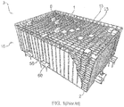
- the storage structure 3 comprises a vehicle or robot 1 which is arranged to move on dedicated supporting rails 13 and to receive a storage bin 2 from a storage column 8 within a bin storage grid 15.
- the storage structure 3 includes a plurality of such vehicles 1 and a dedicated bin lift device 50, the latter being arranged to receive a storage bin 2 from the vehicle 1 at the top level of the bin storing grid 15 and to convey the storage bin 2 down in a vertical direction to a delivery station 60.
- a vehicle 1 When a particular storage bin (denoted a "target bin") on a lower level within the storage structure is to be fetched, a vehicle 1 is controlled to pick up the upper bin from the stack of bins located vertically above the target bin, and then the vehicle 1 is controlled to unload and store this bin on a selected location on the upper level of the storage grid. This process may then be repeated until the target bin has become the upper bin in the vertical stack of bins. Then the target bin is fetched by the vehicle 1 and carried by the vehicle 1 to the bin lift device 50.
- This system and operational method has certain disadvantages. Firstly, the intermediate storage of bins on top of the upper level of the storage grid occupies area, resulting in obstructions for other vehicles that are intended to move as freely as possible on the top of the upper level of the storage grid. Secondly, a substantial amount of time is spent on the loading and unloading of bins associated with the intermediate storage. This in turn contributes to significant delays in the overall pick up time used to obtain a desired target bin.
- WO-2013/167907 relates to a storage system suitable for storing multiple product lines in an automated warehouse environment.
- a first handling device is capable of lifting a plurality of containers from a stack in a single operation
- a second handling device is capable of lifting a single container and moving the container laterally.
- the first handling device lifting a plurality of containers, causes a potentially tall stack of containers to be stored in the first handling device. This results in instability and risk for overturning, in particularly during acceleration/movement of the first handling device.
- a special multi-bin handling device is needed for the lifting of a plurality of containers.
- the multi-bin handling device is different from the single-bin handling device used to retain the single container. The use of dedicated handling devices for various purposes results in a complex system.
- An object of the present invention is to solve, or at least substantially alleviate, the above-described disadvantages of the prior art storage structures and methods.
- the invention provides, i.a., the advantage that the area on top of the upper level of the storage grid will not be blocked by stationary obstructions during retrieval of a desired target bin at a lower level in the storage structure. Hence, other vehicles are allowed to move more freely on the top of the upper level of the storage grid. Although non-target vehicles that serve as intermediate storage for a bin also take up area on the top of the storage grid, the non-target vehicles may be easily moved if necessary.
- An other advantage of the invention is that the time spent on loading and unloading of bins that must be intermediately stored, will be substantially reduced, compared with the methods and systems of the background art. Hence, the invention increases the overall retrieval speed when fetching a desired target bin in the storage structure.
- the feature of controlling the at least one non-target vehicle and the target vehicle to be positioned adjacent to each other in a linear manner on the supporting rails results in substantially improved retrieval speed when fetching a desired target bin in the storage structure.
- Another advantage of the invention is that only one type of vehicle is needed.
- the one type of vehicle may serve as a target vehicle or a non-target vehicle, depending on its current mode of operation.
- Fig. 3 is a schematic flow chart illustrating a method for fetching a target bin stored in a storage system.
- the storage system includes a three-dimensional storage grid containing a plurality of bins stacked in vertical stacks, supporting rails on the grid structure, and a plurality of vehicles, controllably arranged to move on the supporting rails.
- the method starts at the initiating step 300.
- the non-target vehicle control step 310 includes controlling at least one non-target vehicle to operate as intermediate storage for at least one bin located vertically above the target bin.
- the non-target vehicle control step 310 may include several substeps, in order to obtain its task of controlling at least one non-target vehicle to operate as intermediate storage for at least one bin located vertically above the target bin. While other alternatives are also possible, the non-target vehicle control step 310 may, by example, include the following:
- the target vehicle control step 360 includes controlling the target vehicle to pick up the target bin at the target location.
- the at least one non-target vehicle and the target vehicle are controlled to be positioned adjacent to each other in a linear manner on the supporting rails.
- Linear manner may in this context mean that the vehicles are positioned, or are moving, along a line which coincides with or is parallel with the supporting rails on the grid structure. This leads to a particular efficient operation, since it reduces the time needed from one vehicle's performance of a task at the target location to the next vehicle's performance of a task at the target location.
- the target vehicle control step 360 may include the following substeps:
- the method may be terminated at the terminating step 390, subsequent to the target vehicle control step 360.
- the method may include a further step, performed subsequent to the target vehicle control step 360 and prior to the terminating step 390, the further step including controlling the at least one non-target vehicle to return and unload its bin to the target location.
- the non-target vehicles are advantageously controlled to return and unload their bins to the target location in opposite order, compared to the order in which the non-target vehicles picked up their respective non-target bins in the repeated sequence of steps 320, 330, 340 and 350.
- Fig. 4 is a schematic block diagram illustrating a storage system, in particular including communication elements that are suitable in a system and method as disclosed herein.
- the system 400 includes a storage structure 430 which may be similar to the storage structure 3 referred to in the section Background of the invention above.
- the storage system 400 includes a three-dimensional storage grid containing a plurality of bins stacked in vertical stacks; supporting rails on the grid structure; and a plurality of vehicles, controllably arranged to move on the supporting rails.
- a control device 420 is provided.
- the system may include a communication device 410, which facilitates communication, preferably wireless communication, such as digital RF communication, between the control device 420 and each vehicle.
- the communication device 410 is further communicatively connected to the control device 420, either by wire or wireless communication means.
- the communication device 410 and the control device 420 may be separate units or combined into one unit.
- Each vehicle is arranged to move on supporting rails and to receive a storage bin from a storage column within the bin storing grid.
- each, several or all the vehicles may be of the type as illustrated in figure 2 and referred to in the section Background of the invention above.
- each, several or all the vehicles may be of a type that includes a vehicle body and a cavity arranged centrally within the vehicle body, the cavity being arranged to receive and hold a storage bin.
- Each vehicle is provided with rolling means, such as wheels.
- the vehicle includes a first and a second set of wheels, each set including four wheels, and the first set of wheels being arranged perpendicularly to the second set of wheels.
- Such an arrangement may enable the vehicle to move along supporting rails extending in a first direction on the grid structure and along supporting rails extending in a second direction on the grid stricture.
- the first and second directions of the supporting rails are also advantageously perpendicular.
- the vehicle may include a controllable mechanism for selectively displacing, from the rails, either the first or second set of wheels. This arrangement enables controllable, quick change of vehicle direction between the first direction and the second direction.
- At least one wheel in a set of wheels is driven by a motor, typically an electric motor.
- the displacing mechanism may also be actuated electrically.
- the motor and other energy-consuming equipment on the vehicle is typically powered by a rechargeable battery onboard the vehicle.
- each vehicle is advantageously provided with local control/processing means which provides the detailed control of the rotation of wheels and the controllable displacing mechanism.
- Sensors may also be arranged in the vehicles and connected to the control/processing means on the vehicle, and signals provided by such sensors may be used in the local control provided on the vehicle.
- Such sensors may, i.a, include proximity and position sensors, e.g. optical sensors.
- Each vehicle further includes a controllable mechanism which enables the vehicle to pick up (or load) a bin from a location at the storage grid, and/or to drop off (or unload) a bin to a location at the storage grid.
- the control/processing means on the vehicle provides local control of i.a. the speed and rolling direction of wheels, and of the loading/unloading mechanism. This may be achieved by configuring suitable software in a memory included in the vehicle's control/processing means, enabling the control/processing means to control i.a. the rotational direction, speed and acceleration of the vehicle's wheel(s).
- the control/processing means on the vehicle may also be configured to receive instructions or requests from a remote control device, the instructions or requests being on a higher conceptual level than the detailed control of direction, speed, etc..
- the control/processing means on the vehicle may be enabled to receive a request for moving the vehicle to a particular position on the storage grid, or to pick up a bin from the grid at a particular position on the storage grid, and to control the vehicle to move and act accordingly.
- the storage system 400 also includes a control device 420, which may be a computer device, including, i.e., a processing device and a memory which includes a computer program configured to be executed on the processing device.
- a control device 420 may be a computer device, including, i.e., a processing device and a memory which includes a computer program configured to be executed on the processing device.
- the control device 420 is configured to transmit instructions or requests to each vehicle via the communication device 410.
- the control device 420 holds information about each vehicle's position, load status, etc. in an associated memory. Hence, the control device 420 is enabled to transmit instructions or request on a higher conceptual level to each vehicle, as already described above.
- the control device 420 may be configured to identify a "target vehicle”, i.e., a vehicle that is intended to hold a particular bin to be fetched in the storage grid, denoted the "target bin”. To this end, the control device 420 may for instance be configured to select a vehicle that is currently unoccupied and determine that vehicle to be a "target vehicle”.
- the control device 420 may also be configured to identify at least "non-target vehicle", i.e. a vehicle that is intended to be used as an intermediate storage for bins that must be removed in order to obtain the target bin in the storage grid. To this end, the control device 420 may be configured to select a vehicle that is currently unoccupied and determine that vehicle to be a "non-target vehicle". The control device 420 may also be configured to control the non-target vehicles and the target vehicle to place themselves in a set of positions wherein they are prepared to perform an operation of fetching the target bin. In particular, the control device 420 may be configured to control the non-target vehicles and the target vehicle to place themselves adjacent to each other on the supporting rails in a linear manner, and in such a way that a non-target vehicle is located vertically above the target bin.
- non-target vehicle i.e. a vehicle that is intended to be used as an intermediate storage for bins that must be removed in order to obtain the target bin in the storage grid.
- the control device 420 may be configured
- the process of identifying a "target vehicle” and “non-target vehicles” may be distributed to the control/processing means in the vehicles, since each vehicle holds status information which indicates if the vehicle is currently busy, i.e., unavailable for service. or unoccupied, i.e., available for service.
- control device 420 is configured to fetch a target bin stored in the storage system 400 by controlling at least one non-target vehicle to operate as intermediate storage for at least one bin located vertically above the target bin; controlling a target vehicle to pick up the target bin, and controlling the at least one non-target vehicle and the target vehicle to be positioned adjacent to each other in a linear manner on the supporting rails.
- control device 420 is configured to controlling the at least one non-target vehicle to operate as intermediate storage for at least one bin located vertically above the target bin. More specifically, the control device 420 may be configured to control a non-target vehicle to move to a target location above the target bin; control the non-target vehicle to pick up a bin from the vertical stack at the target location; to control the non-target vehicle to a neighbour location; and to repeat the above controlling steps 320, 330, 340 until the target bin has become the upper bin in the vertical stack at the target location.
- control device 420 may also be configured to control the target vehicle to pick up the target bin by: controlling the target vehicle to move to the target location; and controlling the target vehicle to pick up the target bin from the vertical stack at the target location.
- control device 420 may be further configured to control the non-target vehicles to return and unload their bins to the target location.
- control device 420 may also be further configured to control the non-target vehicles to return and unload their bins to the target location in opposite order.
- the control device 420 may include memory that holds and updates data representing various information about the storage system. Such information may include current position and identification of storage bins stored in the storage structure, as well as current position and identification of vehicles that move or are stationary disposed on the supporting rails on the grid structure.
- Figures 5-9 are schematic diagrams illustrating an exemplary operation of the method and system.
- Figure 5 illustrates an initiate situation wherein a number of vehicles (four shown) are available on the top of the storage grid structure.
- the vehicles are arranged to move on supporting rails on the top of the storage grid structure.
- a plurality of bins (ten shown) are stacked in a vertical stack in the three-dimensional storage grid structure. Of these bins, the bin denoted by number "5" is determined to be a target bin.
- Figure 5 also illustrates that a non-target vehicle (the rightmost vehicle in figure 5 ) has been controlled to move to a target location above the target bin.
- Figure 6 illustrates that the non-target vehicle (the rightmost vehicle in figure 6 ), located above the target bin, has been controlled to pick up a bin (denoted by number "1").
- Figure 7 illustrates that the non-target vehicle that holds the bin denoted by number "1" has been controlled to rest at a neighbour position on the storage grid.
- the controlling steps 320, 330, 340 have then been repeated three times.
- further 3 non-target vehicles have been controlled to move to the target location above the target bin and been controlled to pick up a bin from the vertical stack at the target location, and been controlled to rest at a neighbour location.
- the target bin (denoted "5") has become the upper bin in the vertical stack at the target location.
- the repeating of controlling steps320, 330, 340 is terminated.
- Figure 8 illustrates that the target vehicle (the leftmost vehicle in figure 8 ) has been controlled to move to the target location and been controlled to pick up the target bin (denoted "5"). Consequently, the target vehicle has fetched the target bin and may carry the target bin to another location, such as a bin lift device which may cause the target bin to be conveyed to a delivery station.
- the target vehicle the leftmost vehicle in figure 8
- the target vehicle has been controlled to move to the target location and been controlled to pick up the target bin (denoted "5"). Consequently, the target vehicle has fetched the target bin and may carry the target bin to another location, such as a bin lift device which may cause the target bin to be conveyed to a delivery station.
- Figure 9 illustrates that the non-target vehicles have returned and unloaded their bins to the target location. Since the non-target vehicles return and unload their bins to the target location in opposite order, the result will be that the non-target bins appear in the grid structure in their original order. Only the target bin (denoted "5") is missing.
- all the non-target vehicles and the target vehicle are positioned adjacent to each other in a linear manner on the supporting rails at any time during the process of retrieving the target bin. This leads to a particular efficient operation, since it reduces the time needed from one vehicle's performance of a task at the target location to the next vehicle's performance of a task at the target location.
Landscapes
- Engineering & Computer Science (AREA)
- Mechanical Engineering (AREA)
- Physics & Mathematics (AREA)
- Mathematical Physics (AREA)
- Warehouses Or Storage Devices (AREA)
- De-Stacking Of Articles (AREA)
Claims (8)
- Verfahren zum Holen eines Zielbehälters (5), der in einem Lagersystem (400) gelagert ist, wobei das Lagersystem (400) Folgendes beinhaltet: ein dreidimensionales Lagerraster (15), das eine Vielzahl von Behältern enthält, die in senkrechten Stapeln gestapelt sind, Tragschienen (13) auf der Rasterstruktur und
eine Vielzahl von Wagen (1), die steuerbar angeordnet sind, um sich einzeln auf den Tragschienen (13) zu bewegen,
wobei das Verfahren Folgendes umfasst:- Steuern einer Vielzahl von Nichtzielwagen (1), derart dass jeder Nichtzielwagen (1) als eine Zwischenlagerung für einen einzelnen Behälter fungiert, der sich senkrecht über einem Zielbehälter befindet;- Steuern eines Zielwagens (1), damit er den Zielbehälter aufnimmt, und- Steuern der Vielzahl von Nichtzielwagen (1) und des Zielwagens (1), damit sie auf lineare Weise aneinander angrenzend auf den Tragschienen (13) angeordnet sind, wobei die Vielzahl von Nichtzielwagen (1) und der Zielwagen (1) zum gleichen Typ von Wagen gehören, der in der Lage ist, jeweils nur einen einzelnen Behälter anzuheben,wobei der Schritt des Steuerns jedes der Vielzahl von Nichtzielwagen (1), damit diese als Zwischenlagerung für einen einzelnen Behälter fungieren, der sich senkrecht über dem Zielbehälter befindet, ferner Folgendes umfasst:- Steuern eines Nichtzielwagens (1), damit er sich zu einer Zielposition über dem Zielbehälter bewegt;- Steuern des Nichtzielwagens (1), damit er einen einzelnen Behälter von dem senkrechten Stapel an der Zielposition aufnimmt;- Steuern des Nichtzielwagens (1), damit er auf einer benachbarten Position bleibt; und- Bestimmen, ob der Zielbehälter, der obere Behälter in dem senkrechten Stapel an der Zielposition geworden ist und, falls dies nicht der Fall ist, Wiederholen der Steuerungsschritte, bis der Zielbehälter der obere Behälter in dem senkrechten Stapel an der Zielposition geworden ist. - Verfahren nach Anspruch 1, wobei der Schritt des Steuerns des Zielwagens (1), damit er den Zielbehälter aufnimmt, Folgendes umfasst:- Steuern des Zielwagens (1), damit er sich zu der Zielposition bewegt; und- Steuern des Zielwagens (1), damit er den Zielbehälter von dem senkrechten Stapel an der Zielposition aufnimmt.
- Verfahren nach einem der Ansprüche 1-2, ferner umfassend das Steuern jedes aus der Vielzahl von Nichtzielwagen (1), damit dieser zurückkehrt und seinen Behälter an der Zielposition ablädt, in umgekehrter Reihenfolge in Bezug auf die Reihenfolge, in der die Nichtzielwagen (1) ihre Behälter in den Steuerungsschritten aufgenommen haben.
- Verfahren nach einem der vorstehenden Ansprüche, wobei jeder der Nichtzielwagen (1) und der Zielwagen (1) einen Wagenkörper und einen Hohlraum aufweist, der zentral innerhalb des Wagenkörpers angeordnet ist, um einen Lagerbehälter zu empfangen und zu halten.
- Lagersystem (400), beinhaltend- ein dreidimensionales Lagerraster (15), das eine Vielzahl von Behältern enthält, die in senkrechten Stapeln gestapelt sind;- Tragschienen (13) auf der Rasterstruktur; und- eine Vielzahl von Wagen (1), die steuerbar angeordnet sind, um sich auf den Tragschienen (13) zu bewegen, und
eine Steuervorrichtung (420),
wobei die Steuervorrichtung (420) dazu ausgelegt ist, das Holen eines Zielbehälters, der in dem Lagersystem gelagert ist, durch Folgendes zu ermöglichen:- Steuern einer Vielzahl von Nichtzielwagen (1), derart dass jeder Nichtzielwagen (1) als Zwischenlagerung für einen einzelnen Behälter fungiert, der sich senkrecht über dem Zielbehälter befindet;- Steuern eines Zielwagens (1), damit er den Zielbehälter aufnimmt; und- Steuern der Vielzahl von Nichtzielwagen (1) und des Zielwagens (1), damit sie auf lineare Weise aneinander angrenzend auf den Tragschienen angeordnet sind, wobei die Vielzahl von Nichtzielwagen (1) und der Zielwagen (1) zum gleichen Typ von Wagen (1) gehören, der in der Lage ist, jeweils nur einen einzelnen Behälter anzuheben,wobei die Steuervorrichtung (420) dazu ausgelegt ist, jeden von der Vielzahl von Nichtzielwagen (1) durch Folgendes zu steuern, damit dieser als Zwischenlagerung für einen einzelnen Behälter fungiert, der sich senkrecht über dem Zielbehälter befindet:- Steuern eines Nichtzielwagens (1), damit er sich zu einer Zielposition über dem Zielbehälter bewegt;- Steuern des Nichtzielwagens (1), damit er einen einzelnen Behälter von dem senkrechten Stapel an der Zielposition aufnimmt;- Steuern des Nichtzielwagens (1), damit er auf einer benachbarten Position bleibt; und- Bestimmen, ob der Zielbehälter, der obere Behälter in dem senkrechten Stapel an der Zielposition geworden ist und, falls dies nicht der Fall ist,- Wiederholen der Steuerungsschritte, bis der Zielbehälter der obere Behälter in dem senkrechten Stapel an der Zielposition geworden ist. - Lagersystem (400) nach Anspruch 5, wobei die Steuervorrichtung (420) dazu ausgelegt ist, den Zielwagen (1) durch Folgendes zu steuern, damit er den Zielbehälter aufnimmt:- Steuern des Zielwagens (1), damit er sich zu der Zielposition bewegt; und- Steuern des Zielwagens (1), damit er den Zielbehälter von dem senkrechten Stapel an der Zielposition aufnimmt.
- Lagersystem (400) nach einem der Ansprüche 5-6, wobei die Steuervorrichtung (420) ferner dazu ausgelegt ist,- jeden aus der Vielzahl von Zielwagen (1) zu steuern, damit dieser zurückkehrt und seinen Behälter an der Zielposition ablädt, in umgekehrter Reihenfolge in Bezug auf die Reihenfolge, in der die Nichtzielwagen (1) ihre Behälter in den Steuerungsschritten aufgenommen haben.
- Lagersystem (400) nach einem der Ansprüche 5-7, wobei jeder der Nichtzielwagen (1) und der Zielwagen (1) einen Wagenkörper und einen Hohlraum aufweist, der zentral innerhalb des Wagenkörpers angeordnet ist, um einen Lagerbehälter zu empfangen und zu halten.
Priority Applications (1)
| Application Number | Priority Date | Filing Date | Title |
|---|---|---|---|
| PL16760047T PL3344562T3 (pl) | 2015-09-04 | 2016-08-31 | Sposób wydobywania docelowego pojemnika magazynowanego w magazynowym układzie |
Applications Claiming Priority (2)
| Application Number | Priority Date | Filing Date | Title |
|---|---|---|---|
| NO20151135A NO340577B1 (en) | 2015-09-04 | 2015-09-04 | Method for fetching a target bin stored in a storage system and a storage system which includes a control device operating in accordance with the method |
| PCT/EP2016/070476 WO2017037095A1 (en) | 2015-09-04 | 2016-08-31 | Method for fetching a target bin stored in a storage system |
Publications (2)
| Publication Number | Publication Date |
|---|---|
| EP3344562A1 EP3344562A1 (de) | 2018-07-11 |
| EP3344562B1 true EP3344562B1 (de) | 2020-02-12 |
Family
ID=56853621
Family Applications (1)
| Application Number | Title | Priority Date | Filing Date |
|---|---|---|---|
| EP16760047.7A Active EP3344562B1 (de) | 2015-09-04 | 2016-08-31 | Verfahren zum holen eines in einem lagersystem aufbewahrten zielbehälters |
Country Status (11)
| Country | Link |
|---|---|
| US (2) | US10457482B2 (de) |
| EP (1) | EP3344562B1 (de) |
| JP (1) | JP6790076B2 (de) |
| CN (1) | CN108137229B (de) |
| CA (1) | CA2997526C (de) |
| DK (1) | DK3344562T3 (de) |
| ES (1) | ES2780624T3 (de) |
| NO (1) | NO340577B1 (de) |
| PL (1) | PL3344562T3 (de) |
| TW (1) | TW201711937A (de) |
| WO (1) | WO2017037095A1 (de) |
Cited By (1)
| Publication number | Priority date | Publication date | Assignee | Title |
|---|---|---|---|---|
| EP3835236B1 (de) * | 2018-08-10 | 2025-06-11 | Beijing Geekplus Technology Co., Ltd. | Verfahren zum bewegen von gegenständen in einem dichten lager und dichtes lagersystem |
Families Citing this family (34)
| Publication number | Priority date | Publication date | Assignee | Title |
|---|---|---|---|---|
| GB201701615D0 (en) | 2017-02-01 | 2017-03-15 | Ocado Innovation Ltd | Safety system for an automated storage and picking system and method of operating thereof |
| NO20180586A1 (en) | 2018-04-25 | 2019-10-28 | Autostore Tech As | Charging system for container handling vehicles and method of charging a power supply |
| NO343676B1 (en) * | 2017-09-20 | 2019-05-06 | Autostore Tech As | Container handling vehicle |
| NO346519B1 (en) * | 2017-11-02 | 2022-09-19 | Autostore Tech As | An automated storage and retrieval system, use of a multi trolley vehicle on the system and a method of operating the system |
| NO344310B1 (en) | 2017-11-22 | 2019-11-04 | Autostore Tech As | Automated storage and retrieval system comprising a three dimensional grid, container-handling vehicle and method of retrieving at least one storage container from the storage 40 storage and retrieval system |
| NO346364B1 (en) * | 2018-04-25 | 2022-06-27 | Autostore Tech As | Container handling vehicle with first and second sections and battery in second section, and system. |
| EP4556406A1 (de) | 2018-01-09 | 2025-05-21 | AutoStore Technology AS | Verschiebungsmechanismus für ein ferngesteuertes fahrzeug |
| GB201803771D0 (en) | 2018-03-09 | 2018-04-25 | Ocado Innovation Ltd | Transporting device position determining apparatus and method |
| DE102018105614A1 (de) | 2018-03-12 | 2019-09-12 | Sama Beteiligungsgesellschaft Mbh | Blocklager, fahrerloses Transportsystem und Ladungsträger |
| EP3807183B1 (de) * | 2018-06-12 | 2024-09-11 | Autostore Technology AS | Verfahren zum betrieb eines automatischen regalbedienungssystems |
| CN115158949B (zh) | 2018-06-12 | 2025-01-21 | 自动存储科技股份有限公司 | 储存系统、在储存系统中取回和储存物品的方法及转移方法 |
| WO2019238670A1 (en) * | 2018-06-12 | 2019-12-19 | Autostore Technology AS | A method of operating an automated storage and retrieval system |
| NO20181563A1 (en) | 2018-06-12 | 2019-12-13 | Autostore Tech As | Automated storage system and method of retrieving a storage container from storage system |
| JP7373507B2 (ja) * | 2018-06-12 | 2023-11-02 | アウトストア・テクノロジー・エーエス | アクセスポイントを備えた配送システム、および、配送システムのアクセスポイントにアクセスする方法 |
| JP7443256B2 (ja) | 2018-06-12 | 2024-03-05 | アウトストア・テクノロジー・エーエス | 自動倉庫グリッドと第2の場所との間で保管コンテナを輸送する配送車両、自動倉庫システム、および方法 |
| JP7360403B2 (ja) * | 2018-06-12 | 2023-10-12 | アウトストア・テクノロジー・エーエス | 自動収納回収システム向けの容器荷役車両およびドローンの操作を制御する方法およびシステム |
| CN109178743A (zh) * | 2018-08-10 | 2019-01-11 | 北京极智嘉科技有限公司 | 基于密集存储的物品搬移方法、装置、设备和存储介质 |
| NO344988B1 (en) * | 2018-11-05 | 2020-08-10 | Autostore Tech As | A station for providing access to contents in a storage container |
| CN110758975A (zh) * | 2019-01-24 | 2020-02-07 | 中船第九设计研究院工程有限公司 | 一种船厂智能钢料堆场钢板库存信息的数学建模方法 |
| NO346306B1 (en) * | 2019-08-22 | 2022-05-30 | Autostore Tech As | A delivery system, an automated storage and retrieval system and a method of transporting a container |
| NO347754B1 (en) * | 2019-09-02 | 2024-03-18 | Autostore Tech As | Method, and associated system, of providing an operator access to a target storage position in an automated storage and retrieval system |
| NO345589B1 (en) * | 2019-09-26 | 2021-05-03 | Autostore Tech As | System and method for power management |
| NO346795B1 (en) * | 2019-12-03 | 2023-01-16 | Autostore Tech As | Service vehicle providing a platform and method for servicing a container handling vehicle using the service vehicle. |
| DE102019134528A1 (de) * | 2019-12-16 | 2021-06-17 | Amova Gmbh | Verfahren zur dynamischen Verkehrsführung von externen Verkehrsmitteln in einem Hochregallager |
| NO346390B1 (en) * | 2019-12-20 | 2022-07-04 | Autostore Tech As | Track sensor arrangement for a remotely operated vehicle and a method thereof |
| NO346304B1 (en) | 2020-06-25 | 2022-05-30 | Autostore Tech As | System and method of operating an automated storage and retrieval system |
| NO20200927A1 (en) * | 2020-08-26 | 2022-02-28 | Autostore Tech As | Routing of container handling vehicles operating an automated storage system |
| CN121084813A (zh) * | 2020-10-23 | 2025-12-09 | 北京极智嘉科技股份有限公司 | 一种取箱方法以及取箱设备 |
| NO346367B1 (en) * | 2020-11-17 | 2022-06-27 | Autostore Tech As | Method, system and computer program product of controlling movement of container handling vehicles |
| US12578738B2 (en) * | 2020-12-24 | 2026-03-17 | Ocado Innovation Limited | Motion control of a robotic load handling device |
| NO346982B1 (en) * | 2021-06-30 | 2023-03-27 | Autostore Tech As | System, method and computer program product of determining a position of a container handling vehicle in an automated grid based storage and retrieval system |
| AT525328B1 (de) | 2021-07-16 | 2023-07-15 | Perstling Ing Manuel | Verfahren zum Betreiben eines Regallagers, sowie ein Regallager, Fahrwagen und Hubeinheit hierfür |
| WO2023126871A1 (de) | 2021-12-30 | 2023-07-06 | Noyes Technologies Gmbh | Modulares lagersystem, verfahren zum aufbau eines lagersystems und verfahren zur lagerung |
| JP7564922B1 (ja) | 2023-04-26 | 2024-10-09 | 泰科動力股▲分▼有限公司 | 物品搬送方法及び立体倉庫システム |
Citations (1)
| Publication number | Priority date | Publication date | Assignee | Title |
|---|---|---|---|---|
| WO2013167907A1 (en) * | 2012-05-11 | 2013-11-14 | Ocado Limited | Storage systems and methods for retrieving units from a storage system |
Family Cites Families (14)
| Publication number | Priority date | Publication date | Assignee | Title |
|---|---|---|---|---|
| US2701065A (en) * | 1950-09-06 | 1955-02-01 | Charles A Bertel | Apparatus for storing and handling containers |
| US3786929A (en) * | 1971-11-01 | 1974-01-22 | Conco Inc | Warehousing system using slowdown and stop bin indicators |
| FI105668B (fi) * | 1995-10-02 | 2000-09-29 | Cimcorp Oy | Poimintajärjestelmä |
| NO972004D0 (no) | 1997-04-30 | 1997-04-30 | Hatteland Electronic As Jacob | Metode for organisering av vareflyt for en horisontalt lagdelt og dypstablet lagerbeholdning med uensartede komponenter, samt forflytningsutstyr for standariserte beholdere til formålet |
| EP2790210A3 (de) * | 2002-06-19 | 2014-12-31 | Murata Machinery, Ltd. | Automatisiertes Materialhandhabungssystem |
| US8651790B2 (en) * | 2006-09-25 | 2014-02-18 | Charles E. Benedict | Warehouse storage system |
| US7591630B2 (en) * | 2003-08-29 | 2009-09-22 | Casepick Systems, Llc | Materials-handling system using autonomous transfer and transport vehicles |
| US8276739B2 (en) * | 2007-01-25 | 2012-10-02 | Bastian Material Handling, Llc | Three-dimensional automated pick module |
| AT506887A1 (de) * | 2008-05-26 | 2009-12-15 | Tgw Mechanics Gmbh | Lagersystem und verfahren zum betreiben desselben |
| US9701475B2 (en) * | 2009-03-11 | 2017-07-11 | Parking Kit Ltd. | Modular storage system |
| EP3223088B1 (de) * | 2013-01-28 | 2022-10-19 | Amazon Technologies, Inc. | Inventarisierungssystem mit verbindbaren bestandsträgern |
| EP2999647A4 (de) * | 2013-05-21 | 2017-02-15 | Sodium Limited | System und verfahren zur erzeugung einer strukturierten menge von behältern |
| NO338156B1 (no) * | 2014-02-19 | 2016-08-01 | Jakob Hatteland Logistics As | Avkjølt lagringssystem |
| US20160016731A1 (en) * | 2014-07-16 | 2016-01-21 | Sergey N. Razumov | Loading desired container sequence onto board of container carriage in storage system |
-
2015
- 2015-09-04 NO NO20151135A patent/NO340577B1/en unknown
-
2016
- 2016-08-31 JP JP2018511619A patent/JP6790076B2/ja active Active
- 2016-08-31 DK DK16760047.7T patent/DK3344562T3/da active
- 2016-08-31 WO PCT/EP2016/070476 patent/WO2017037095A1/en not_active Ceased
- 2016-08-31 CA CA2997526A patent/CA2997526C/en active Active
- 2016-08-31 ES ES16760047T patent/ES2780624T3/es active Active
- 2016-08-31 US US15/757,577 patent/US10457482B2/en active Active
- 2016-08-31 CN CN201680061772.3A patent/CN108137229B/zh active Active
- 2016-08-31 PL PL16760047T patent/PL3344562T3/pl unknown
- 2016-08-31 EP EP16760047.7A patent/EP3344562B1/de active Active
- 2016-09-02 TW TW105128390A patent/TW201711937A/zh unknown
-
2019
- 2019-09-05 US US16/561,039 patent/US10858186B2/en active Active
Patent Citations (1)
| Publication number | Priority date | Publication date | Assignee | Title |
|---|---|---|---|---|
| WO2013167907A1 (en) * | 2012-05-11 | 2013-11-14 | Ocado Limited | Storage systems and methods for retrieving units from a storage system |
Cited By (1)
| Publication number | Priority date | Publication date | Assignee | Title |
|---|---|---|---|---|
| EP3835236B1 (de) * | 2018-08-10 | 2025-06-11 | Beijing Geekplus Technology Co., Ltd. | Verfahren zum bewegen von gegenständen in einem dichten lager und dichtes lagersystem |
Also Published As
| Publication number | Publication date |
|---|---|
| EP3344562A1 (de) | 2018-07-11 |
| NO20151135A1 (en) | 2017-03-06 |
| PL3344562T3 (pl) | 2020-07-13 |
| DK3344562T3 (da) | 2020-03-30 |
| CN108137229B (zh) | 2020-01-03 |
| US20180244467A1 (en) | 2018-08-30 |
| JP2018528134A (ja) | 2018-09-27 |
| CN108137229A (zh) | 2018-06-08 |
| US10858186B2 (en) | 2020-12-08 |
| TW201711937A (en) | 2017-04-01 |
| ES2780624T3 (es) | 2020-08-26 |
| JP6790076B2 (ja) | 2020-11-25 |
| US20190389656A1 (en) | 2019-12-26 |
| US10457482B2 (en) | 2019-10-29 |
| CA2997526C (en) | 2023-10-10 |
| NO340577B1 (en) | 2017-05-15 |
| WO2017037095A1 (en) | 2017-03-09 |
| CA2997526A1 (en) | 2017-03-09 |
Similar Documents
| Publication | Publication Date | Title |
|---|---|---|
| US10858186B2 (en) | Method for fetching a target bin stored in a storage system | |
| EP3402731B1 (de) | Lagersystem für die lagerung und den transport von behältern | |
| EP3715284B1 (de) | Automatisches system und verfahren zum lagern von materialien und zum zusammenbauen von verpackungen daraus | |
| CN112585069B (zh) | 用于控制服务于自动储存和取回系统的容器搬运车辆和专用车辆的操作的方法和系统 | |
| CN114402269A (zh) | 用于自动控制在自动存储和取回系统中操作的集装箱搬运车辆的移动的方法和系统 | |
| US12596967B2 (en) | Method and system for picking products in a picking station of an automatic storage and retrieval system | |
| CN112262084A (zh) | 操作自动储存和取回系统的方法 | |
| WO2019238687A1 (en) | A method and system for controlling the operation of container handling vehicles and drones serving an automated storage and retrieval system | |
| US9963294B2 (en) | Arrangement and method in a warehouse | |
| JP7524088B2 (ja) | プログラム | |
| HK1254152A1 (en) | Method for fetching a target bin stored in a storage system | |
| HK1254152B (zh) | 用於提取存储在存储系统中的目标箱的方法 | |
| WO2024133300A1 (en) | Method, system and computer program product for moving a storage container | |
| JPH0733214A (ja) | 立体自動倉庫 | |
| EP4534451A1 (de) | Informationsverarbeitungsvorrichtung, informationsverarbeitungsverfahren, programm, system und computerlesbares speichermedium | |
| CN121464063A (zh) | 对在自动储存和取出系统上运行的容器搬运车辆充电 | |
| HK40064819A (en) | A method and system for autonomous controlling of movements of container handling vehicles operating in an automated storage and retrieval system | |
| HK40040385B (en) | A method and system for controlling the operation of container handling vehicles and drones serving an automated storage and retrieval system | |
| HK40040385A (en) | A method and system for controlling the operation of container handling vehicles and drones serving an automated storage and retrieval system |
Legal Events
| Date | Code | Title | Description |
|---|---|---|---|
| STAA | Information on the status of an ep patent application or granted ep patent |
Free format text: STATUS: THE INTERNATIONAL PUBLICATION HAS BEEN MADE |
|
| PUAI | Public reference made under article 153(3) epc to a published international application that has entered the european phase |
Free format text: ORIGINAL CODE: 0009012 |
|
| STAA | Information on the status of an ep patent application or granted ep patent |
Free format text: STATUS: REQUEST FOR EXAMINATION WAS MADE |
|
| 17P | Request for examination filed |
Effective date: 20180319 |
|
| AK | Designated contracting states |
Kind code of ref document: A1 Designated state(s): AL AT BE BG CH CY CZ DE DK EE ES FI FR GB GR HR HU IE IS IT LI LT LU LV MC MK MT NL NO PL PT RO RS SE SI SK SM TR |
|
| AX | Request for extension of the european patent |
Extension state: BA ME |
|
| DAV | Request for validation of the european patent (deleted) | ||
| DAX | Request for extension of the european patent (deleted) | ||
| GRAP | Despatch of communication of intention to grant a patent |
Free format text: ORIGINAL CODE: EPIDOSNIGR1 |
|
| STAA | Information on the status of an ep patent application or granted ep patent |
Free format text: STATUS: GRANT OF PATENT IS INTENDED |
|
| INTG | Intention to grant announced |
Effective date: 20190926 |
|
| GRAS | Grant fee paid |
Free format text: ORIGINAL CODE: EPIDOSNIGR3 |
|
| GRAA | (expected) grant |
Free format text: ORIGINAL CODE: 0009210 |
|
| STAA | Information on the status of an ep patent application or granted ep patent |
Free format text: STATUS: THE PATENT HAS BEEN GRANTED |
|
| AK | Designated contracting states |
Kind code of ref document: B1 Designated state(s): AL AT BE BG CH CY CZ DE DK EE ES FI FR GB GR HR HU IE IS IT LI LT LU LV MC MK MT NL NO PL PT RO RS SE SI SK SM TR |
|
| REG | Reference to a national code |
Ref country code: GB Ref legal event code: FG4D |
|
| REG | Reference to a national code |
Ref country code: CH Ref legal event code: EP |
|
| REG | Reference to a national code |
Ref country code: AT Ref legal event code: REF Ref document number: 1231816 Country of ref document: AT Kind code of ref document: T Effective date: 20200215 |
|
| REG | Reference to a national code |
Ref country code: IE Ref legal event code: FG4D |
|
| REG | Reference to a national code |
Ref country code: DE Ref legal event code: R096 Ref document number: 602016029597 Country of ref document: DE |
|
| REG | Reference to a national code |
Ref country code: DK Ref legal event code: T3 Effective date: 20200326 |
|
| REG | Reference to a national code |
Ref country code: NL Ref legal event code: FP |
|
| REG | Reference to a national code |
Ref country code: SE Ref legal event code: TRGR |
|
| PG25 | Lapsed in a contracting state [announced via postgrant information from national office to epo] |
Ref country code: FI Free format text: LAPSE BECAUSE OF FAILURE TO SUBMIT A TRANSLATION OF THE DESCRIPTION OR TO PAY THE FEE WITHIN THE PRESCRIBED TIME-LIMIT Effective date: 20200212 Ref country code: NO Free format text: LAPSE BECAUSE OF FAILURE TO SUBMIT A TRANSLATION OF THE DESCRIPTION OR TO PAY THE FEE WITHIN THE PRESCRIBED TIME-LIMIT Effective date: 20200512 Ref country code: RS Free format text: LAPSE BECAUSE OF FAILURE TO SUBMIT A TRANSLATION OF THE DESCRIPTION OR TO PAY THE FEE WITHIN THE PRESCRIBED TIME-LIMIT Effective date: 20200212 |
|
| REG | Reference to a national code |
Ref country code: LT Ref legal event code: MG4D |
|
| REG | Reference to a national code |
Ref country code: ES Ref legal event code: FG2A Ref document number: 2780624 Country of ref document: ES Kind code of ref document: T3 Effective date: 20200826 |
|
| PG25 | Lapsed in a contracting state [announced via postgrant information from national office to epo] |
Ref country code: BG Free format text: LAPSE BECAUSE OF FAILURE TO SUBMIT A TRANSLATION OF THE DESCRIPTION OR TO PAY THE FEE WITHIN THE PRESCRIBED TIME-LIMIT Effective date: 20200512 Ref country code: HR Free format text: LAPSE BECAUSE OF FAILURE TO SUBMIT A TRANSLATION OF THE DESCRIPTION OR TO PAY THE FEE WITHIN THE PRESCRIBED TIME-LIMIT Effective date: 20200212 Ref country code: LV Free format text: LAPSE BECAUSE OF FAILURE TO SUBMIT A TRANSLATION OF THE DESCRIPTION OR TO PAY THE FEE WITHIN THE PRESCRIBED TIME-LIMIT Effective date: 20200212 Ref country code: GR Free format text: LAPSE BECAUSE OF FAILURE TO SUBMIT A TRANSLATION OF THE DESCRIPTION OR TO PAY THE FEE WITHIN THE PRESCRIBED TIME-LIMIT Effective date: 20200513 Ref country code: IS Free format text: LAPSE BECAUSE OF FAILURE TO SUBMIT A TRANSLATION OF THE DESCRIPTION OR TO PAY THE FEE WITHIN THE PRESCRIBED TIME-LIMIT Effective date: 20200612 |
|
| PG25 | Lapsed in a contracting state [announced via postgrant information from national office to epo] |
Ref country code: RO Free format text: LAPSE BECAUSE OF FAILURE TO SUBMIT A TRANSLATION OF THE DESCRIPTION OR TO PAY THE FEE WITHIN THE PRESCRIBED TIME-LIMIT Effective date: 20200212 Ref country code: CZ Free format text: LAPSE BECAUSE OF FAILURE TO SUBMIT A TRANSLATION OF THE DESCRIPTION OR TO PAY THE FEE WITHIN THE PRESCRIBED TIME-LIMIT Effective date: 20200212 Ref country code: SK Free format text: LAPSE BECAUSE OF FAILURE TO SUBMIT A TRANSLATION OF THE DESCRIPTION OR TO PAY THE FEE WITHIN THE PRESCRIBED TIME-LIMIT Effective date: 20200212 Ref country code: EE Free format text: LAPSE BECAUSE OF FAILURE TO SUBMIT A TRANSLATION OF THE DESCRIPTION OR TO PAY THE FEE WITHIN THE PRESCRIBED TIME-LIMIT Effective date: 20200212 Ref country code: SM Free format text: LAPSE BECAUSE OF FAILURE TO SUBMIT A TRANSLATION OF THE DESCRIPTION OR TO PAY THE FEE WITHIN THE PRESCRIBED TIME-LIMIT Effective date: 20200212 Ref country code: LT Free format text: LAPSE BECAUSE OF FAILURE TO SUBMIT A TRANSLATION OF THE DESCRIPTION OR TO PAY THE FEE WITHIN THE PRESCRIBED TIME-LIMIT Effective date: 20200212 Ref country code: PT Free format text: LAPSE BECAUSE OF FAILURE TO SUBMIT A TRANSLATION OF THE DESCRIPTION OR TO PAY THE FEE WITHIN THE PRESCRIBED TIME-LIMIT Effective date: 20200705 |
|
| REG | Reference to a national code |
Ref country code: DE Ref legal event code: R097 Ref document number: 602016029597 Country of ref document: DE |
|
| REG | Reference to a national code |
Ref country code: AT Ref legal event code: MK05 Ref document number: 1231816 Country of ref document: AT Kind code of ref document: T Effective date: 20200212 |
|
| PLBE | No opposition filed within time limit |
Free format text: ORIGINAL CODE: 0009261 |
|
| STAA | Information on the status of an ep patent application or granted ep patent |
Free format text: STATUS: NO OPPOSITION FILED WITHIN TIME LIMIT |
|
| 26N | No opposition filed |
Effective date: 20201113 |
|
| PG25 | Lapsed in a contracting state [announced via postgrant information from national office to epo] |
Ref country code: AT Free format text: LAPSE BECAUSE OF FAILURE TO SUBMIT A TRANSLATION OF THE DESCRIPTION OR TO PAY THE FEE WITHIN THE PRESCRIBED TIME-LIMIT Effective date: 20200212 |
|
| PG25 | Lapsed in a contracting state [announced via postgrant information from national office to epo] |
Ref country code: SI Free format text: LAPSE BECAUSE OF FAILURE TO SUBMIT A TRANSLATION OF THE DESCRIPTION OR TO PAY THE FEE WITHIN THE PRESCRIBED TIME-LIMIT Effective date: 20200212 |
|
| PG25 | Lapsed in a contracting state [announced via postgrant information from national office to epo] |
Ref country code: MC Free format text: LAPSE BECAUSE OF FAILURE TO SUBMIT A TRANSLATION OF THE DESCRIPTION OR TO PAY THE FEE WITHIN THE PRESCRIBED TIME-LIMIT Effective date: 20200212 |
|
| PG25 | Lapsed in a contracting state [announced via postgrant information from national office to epo] |
Ref country code: LU Free format text: LAPSE BECAUSE OF NON-PAYMENT OF DUE FEES Effective date: 20200831 |
|
| PG25 | Lapsed in a contracting state [announced via postgrant information from national office to epo] |
Ref country code: IE Free format text: LAPSE BECAUSE OF NON-PAYMENT OF DUE FEES Effective date: 20200831 |
|
| PG25 | Lapsed in a contracting state [announced via postgrant information from national office to epo] |
Ref country code: TR Free format text: LAPSE BECAUSE OF FAILURE TO SUBMIT A TRANSLATION OF THE DESCRIPTION OR TO PAY THE FEE WITHIN THE PRESCRIBED TIME-LIMIT Effective date: 20200212 Ref country code: MT Free format text: LAPSE BECAUSE OF FAILURE TO SUBMIT A TRANSLATION OF THE DESCRIPTION OR TO PAY THE FEE WITHIN THE PRESCRIBED TIME-LIMIT Effective date: 20200212 Ref country code: CY Free format text: LAPSE BECAUSE OF FAILURE TO SUBMIT A TRANSLATION OF THE DESCRIPTION OR TO PAY THE FEE WITHIN THE PRESCRIBED TIME-LIMIT Effective date: 20200212 |
|
| PG25 | Lapsed in a contracting state [announced via postgrant information from national office to epo] |
Ref country code: MK Free format text: LAPSE BECAUSE OF FAILURE TO SUBMIT A TRANSLATION OF THE DESCRIPTION OR TO PAY THE FEE WITHIN THE PRESCRIBED TIME-LIMIT Effective date: 20200212 Ref country code: AL Free format text: LAPSE BECAUSE OF FAILURE TO SUBMIT A TRANSLATION OF THE DESCRIPTION OR TO PAY THE FEE WITHIN THE PRESCRIBED TIME-LIMIT Effective date: 20200212 |
|
| P01 | Opt-out of the competence of the unified patent court (upc) registered |
Effective date: 20230524 |
|
| REG | Reference to a national code |
Ref country code: GB Ref legal event code: 732E Free format text: REGISTERED BETWEEN 20231019 AND 20231025 |
|
| PGFP | Annual fee paid to national office [announced via postgrant information from national office to epo] |
Ref country code: NL Payment date: 20250825 Year of fee payment: 10 |
|
| PGFP | Annual fee paid to national office [announced via postgrant information from national office to epo] |
Ref country code: ES Payment date: 20250909 Year of fee payment: 10 |
|
| PGFP | Annual fee paid to national office [announced via postgrant information from national office to epo] |
Ref country code: DK Payment date: 20250825 Year of fee payment: 10 Ref country code: DE Payment date: 20250827 Year of fee payment: 10 |
|
| PGFP | Annual fee paid to national office [announced via postgrant information from national office to epo] |
Ref country code: PL Payment date: 20250814 Year of fee payment: 10 Ref country code: IT Payment date: 20250821 Year of fee payment: 10 |
|
| PGFP | Annual fee paid to national office [announced via postgrant information from national office to epo] |
Ref country code: GB Payment date: 20250820 Year of fee payment: 10 Ref country code: BE Payment date: 20250825 Year of fee payment: 10 |
|
| PGFP | Annual fee paid to national office [announced via postgrant information from national office to epo] |
Ref country code: FR Payment date: 20250819 Year of fee payment: 10 |
|
| PGFP | Annual fee paid to national office [announced via postgrant information from national office to epo] |
Ref country code: CH Payment date: 20250901 Year of fee payment: 10 Ref country code: SE Payment date: 20250825 Year of fee payment: 10 |