EP3343079B1 - Électrovanne - Google Patents
Électrovanne Download PDFInfo
- Publication number
- EP3343079B1 EP3343079B1 EP16838992.2A EP16838992A EP3343079B1 EP 3343079 B1 EP3343079 B1 EP 3343079B1 EP 16838992 A EP16838992 A EP 16838992A EP 3343079 B1 EP3343079 B1 EP 3343079B1
- Authority
- EP
- European Patent Office
- Prior art keywords
- valve
- iron core
- intermediate member
- movable iron
- gap
- Prior art date
- Legal status (The legal status is an assumption and is not a legal conclusion. Google has not performed a legal analysis and makes no representation as to the accuracy of the status listed.)
- Active
Links
- XEEYBQQBJWHFJM-UHFFFAOYSA-N Iron Chemical group [Fe] XEEYBQQBJWHFJM-UHFFFAOYSA-N 0.000 claims description 118
- 238000000034 method Methods 0.000 claims description 7
- 238000011144 upstream manufacturing Methods 0.000 claims description 5
- 239000000446 fuel Substances 0.000 description 84
- 238000002347 injection Methods 0.000 description 57
- 239000007924 injection Substances 0.000 description 57
- 230000002093 peripheral effect Effects 0.000 description 23
- 238000006073 displacement reaction Methods 0.000 description 12
- 230000000694 effects Effects 0.000 description 7
- 238000002485 combustion reaction Methods 0.000 description 6
- 230000008569 process Effects 0.000 description 5
- 230000004907 flux Effects 0.000 description 3
- 230000000149 penetrating effect Effects 0.000 description 3
- 238000000889 atomisation Methods 0.000 description 2
- 239000000463 material Substances 0.000 description 2
- 239000011347 resin Substances 0.000 description 2
- 229920005989 resin Polymers 0.000 description 2
- 230000004044 response Effects 0.000 description 2
- 239000007921 spray Substances 0.000 description 2
- 230000006641 stabilisation Effects 0.000 description 2
- 238000011105 stabilization Methods 0.000 description 2
- 238000005352 clarification Methods 0.000 description 1
- 238000001914 filtration Methods 0.000 description 1
- 238000003780 insertion Methods 0.000 description 1
- 230000037431 insertion Effects 0.000 description 1
- 238000010030 laminating Methods 0.000 description 1
- 239000007769 metal material Substances 0.000 description 1
- 238000007747 plating Methods 0.000 description 1
- 230000009467 reduction Effects 0.000 description 1
- 239000000243 solution Substances 0.000 description 1
- 238000009331 sowing Methods 0.000 description 1
- 230000000087 stabilizing effect Effects 0.000 description 1
Images


Classifications
-
- F—MECHANICAL ENGINEERING; LIGHTING; HEATING; WEAPONS; BLASTING
- F02—COMBUSTION ENGINES; HOT-GAS OR COMBUSTION-PRODUCT ENGINE PLANTS
- F02M—SUPPLYING COMBUSTION ENGINES IN GENERAL WITH COMBUSTIBLE MIXTURES OR CONSTITUENTS THEREOF
- F02M51/00—Fuel-injection apparatus characterised by being operated electrically
- F02M51/06—Injectors peculiar thereto with means directly operating the valve needle
- F02M51/061—Injectors peculiar thereto with means directly operating the valve needle using electromagnetic operating means
- F02M51/0625—Injectors peculiar thereto with means directly operating the valve needle using electromagnetic operating means characterised by arrangement of mobile armatures
- F02M51/0664—Injectors peculiar thereto with means directly operating the valve needle using electromagnetic operating means characterised by arrangement of mobile armatures having a cylindrically or partly cylindrically shaped armature, e.g. entering the winding; having a plate-shaped or undulated armature entering the winding
- F02M51/0685—Injectors peculiar thereto with means directly operating the valve needle using electromagnetic operating means characterised by arrangement of mobile armatures having a cylindrically or partly cylindrically shaped armature, e.g. entering the winding; having a plate-shaped or undulated armature entering the winding the armature and the valve being allowed to move relatively to each other or not being attached to each other
-
- F—MECHANICAL ENGINEERING; LIGHTING; HEATING; WEAPONS; BLASTING
- F02—COMBUSTION ENGINES; HOT-GAS OR COMBUSTION-PRODUCT ENGINE PLANTS
- F02M—SUPPLYING COMBUSTION ENGINES IN GENERAL WITH COMBUSTIBLE MIXTURES OR CONSTITUENTS THEREOF
- F02M61/00—Fuel-injectors not provided for in groups F02M39/00 - F02M57/00 or F02M67/00
- F02M61/04—Fuel-injectors not provided for in groups F02M39/00 - F02M57/00 or F02M67/00 having valves, e.g. having a plurality of valves in series
- F02M61/10—Other injectors with elongated valve bodies, i.e. of needle-valve type
-
- F—MECHANICAL ENGINEERING; LIGHTING; HEATING; WEAPONS; BLASTING
- F02—COMBUSTION ENGINES; HOT-GAS OR COMBUSTION-PRODUCT ENGINE PLANTS
- F02M—SUPPLYING COMBUSTION ENGINES IN GENERAL WITH COMBUSTIBLE MIXTURES OR CONSTITUENTS THEREOF
- F02M51/00—Fuel-injection apparatus characterised by being operated electrically
- F02M51/06—Injectors peculiar thereto with means directly operating the valve needle
- F02M51/061—Injectors peculiar thereto with means directly operating the valve needle using electromagnetic operating means
- F02M51/0625—Injectors peculiar thereto with means directly operating the valve needle using electromagnetic operating means characterised by arrangement of mobile armatures
- F02M51/0664—Injectors peculiar thereto with means directly operating the valve needle using electromagnetic operating means characterised by arrangement of mobile armatures having a cylindrically or partly cylindrically shaped armature, e.g. entering the winding; having a plate-shaped or undulated armature entering the winding
- F02M51/0671—Injectors peculiar thereto with means directly operating the valve needle using electromagnetic operating means characterised by arrangement of mobile armatures having a cylindrically or partly cylindrically shaped armature, e.g. entering the winding; having a plate-shaped or undulated armature entering the winding the armature having an elongated valve body attached thereto
- F02M51/0682—Injectors peculiar thereto with means directly operating the valve needle using electromagnetic operating means characterised by arrangement of mobile armatures having a cylindrically or partly cylindrically shaped armature, e.g. entering the winding; having a plate-shaped or undulated armature entering the winding the armature having an elongated valve body attached thereto the body being hollow and its interior communicating with the fuel flow
-
- F—MECHANICAL ENGINEERING; LIGHTING; HEATING; WEAPONS; BLASTING
- F16—ENGINEERING ELEMENTS AND UNITS; GENERAL MEASURES FOR PRODUCING AND MAINTAINING EFFECTIVE FUNCTIONING OF MACHINES OR INSTALLATIONS; THERMAL INSULATION IN GENERAL
- F16K—VALVES; TAPS; COCKS; ACTUATING-FLOATS; DEVICES FOR VENTING OR AERATING
- F16K31/00—Actuating devices; Operating means; Releasing devices
- F16K31/02—Actuating devices; Operating means; Releasing devices electric; magnetic
- F16K31/06—Actuating devices; Operating means; Releasing devices electric; magnetic using a magnet, e.g. diaphragm valves, cutting off by means of a liquid
- F16K31/0644—One-way valve
- F16K31/0651—One-way valve the fluid passing through the solenoid coil
-
- H—ELECTRICITY
- H01—ELECTRIC ELEMENTS
- H01F—MAGNETS; INDUCTANCES; TRANSFORMERS; SELECTION OF MATERIALS FOR THEIR MAGNETIC PROPERTIES
- H01F7/00—Magnets
- H01F7/06—Electromagnets; Actuators including electromagnets
- H01F7/08—Electromagnets; Actuators including electromagnets with armatures
- H01F7/16—Rectilinearly-movable armatures
-
- F—MECHANICAL ENGINEERING; LIGHTING; HEATING; WEAPONS; BLASTING
- F02—COMBUSTION ENGINES; HOT-GAS OR COMBUSTION-PRODUCT ENGINE PLANTS
- F02M—SUPPLYING COMBUSTION ENGINES IN GENERAL WITH COMBUSTIBLE MIXTURES OR CONSTITUENTS THEREOF
- F02M51/00—Fuel-injection apparatus characterised by being operated electrically
- F02M51/06—Injectors peculiar thereto with means directly operating the valve needle
- F02M51/061—Injectors peculiar thereto with means directly operating the valve needle using electromagnetic operating means
- F02M51/0614—Injectors peculiar thereto with means directly operating the valve needle using electromagnetic operating means characterised by arrangement of electromagnets or fixed armature
- F02M51/0617—Injectors peculiar thereto with means directly operating the valve needle using electromagnetic operating means characterised by arrangement of electromagnets or fixed armature having two or more electromagnets
- F02M51/0621—Injectors peculiar thereto with means directly operating the valve needle using electromagnetic operating means characterised by arrangement of electromagnets or fixed armature having two or more electromagnets acting on one mobile armature
-
- F—MECHANICAL ENGINEERING; LIGHTING; HEATING; WEAPONS; BLASTING
- F02—COMBUSTION ENGINES; HOT-GAS OR COMBUSTION-PRODUCT ENGINE PLANTS
- F02M—SUPPLYING COMBUSTION ENGINES IN GENERAL WITH COMBUSTIBLE MIXTURES OR CONSTITUENTS THEREOF
- F02M61/00—Fuel-injectors not provided for in groups F02M39/00 - F02M57/00 or F02M67/00
- F02M61/16—Details not provided for in, or of interest apart from, the apparatus of groups F02M61/02 - F02M61/14
- F02M61/168—Assembling; Disassembling; Manufacturing; Adjusting
Definitions
- the present invention relates to an electromagnetic valve.
- a structure in which an intermediate member slidable on both a movable iron core and a valve body and forming a gap in a displacement direction between the movable iron core and the valve body in a closed valve state (refer to, for example, PTL 1) .
- PTL 1 a closed valve state
- WO 2014/141757A1 an electromagnetic fuel injection valve is described.
- a structure is suggested in which both end surfaces of an inner peripheral-side core section and an outer peripheral-side core section face a moving core.
- the structure has a non-magnetic section comprising a metal material between both end surfaces and energy is added to a target member that is to be treated with heat from a different surface than the surfaces facing the moving core, producing heat in the target member.
- a valve body of an electromagnetic fuel injection valve that comprises a second valve body in contact with the anchor when the valve is closed, and a first valve body in contact with the anchor while the valve is opening.
- the second valve body comes in contact with a stroke stopper disposed on the inner periphery of the stationary core when the valve opens, the lengths of the first valve body and the second valve body are stipulated so that the stationary core and the anchor do not come into direct contact and a gap is ensured when the valve opens, and the process of plating the stationary core and the anchor is discontinued.
- PTL 1 by providing a gap in a displacement direction on a movable iron core and a valve body, only the movable iron core is operated before starting energization, an impact force at collision is applied to the valve body during valve opening, and a low lift period is shortened. Further, by providing an intermediate member between the movable iron core and the valve body, relative movement between the valve body and the movable iron core is allowed, and an injection amount is stabilized.
- an object of the present invention is to provide an electromagnetic valve capable of stabilizing an injection amount even when injection is performed while an intermediate member continues to be displaced after valve closing and returns to a closed valve standby state.
- the present invention provides an electromagnetic valve according to claim 1.
- an electromagnetic valve can stabilize an injection amount even when injection is performed while an intermediate member continues to be displaced after valve closing and returns to a closed valve standby state. Issues, configurations, and effects other than the above are clarified by descriptions of the following embodiment.
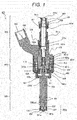
- FIG. 1 is a cross-sectional view illustrating a structure of a fuel injection device according to the first embodiment of the present invention, and is a longitudinal sectional view illustrating a cut surface parallel to a center axis 100a.
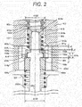
- FIG. 2 is an enlarged cross-sectional view of an electromagnetic drive unit 400 illustrated in FIG. 1 .
- FIG. 3 is a view illustrating operation of a movable iron core 404.
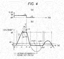
- FIGS. 3(a) and 4(a) illustrate ON/OFF states of an injection command pulse.
- FIGS. 1 is a cross-sectional view illustrating a structure of a fuel injection device according to the first embodiment of the present invention, and is a longitudinal sectional view illustrating a cut surface parallel to a center axis 100a.
- FIG. 2 is an enlarged cross-sectional view of an electromagnetic drive unit 400 illustrated in FIG. 1 .
- FIG. 3 is a view illustrating operation of a movable iron core 404.
- FIG. 5 is a cross-sectional view (schematic view) illustrating operation of a movable portion.
- a recessed portion 404b of the movable iron core 404 illustrated in FIG. 2 is omitted as appropriate.
- the fuel injection device 100 includes a fuel supply unit 200, a nozzle unit 300, and an electromagnetic drive unit 400.
- the fuel supply unit 200 supplies fuel.
- a valve unit 300a for permitting or interrupting fuel flow is provided.
- the electromagnetic drive unit 400 drives the valve unit 300a.
- a fuel injection device for an internal combustion engine using gasoline as a fuel will be described as an example.
- the fuel supply unit 200, the valve unit 300a, the nozzle unit 300, and the electromagnetic drive unit 400 indicate corresponding portions with respect to the cross section illustrated in FIG. 1 and do not indicate a single component.
- the fuel injection device 100 includes the fuel supply unit 200 illustrated at the upper end side of the drawing, the nozzle unit 300 illustrated at the lower end side, and the electromagnetic drive unit 400 provided between the fuel supply unit 200 and the nozzle unit 300. That is, the fuel supply unit 200, the electromagnetic drive unit 400, and the nozzle unit 300 are disposed in this order along a direction of the center axis 100a.
- An end portion of the fuel supply unit 200 on the opposite side of the nozzle unit 300 is connected to a fuel pipe, which is not illustrated.
- An end portion of the nozzle unit 300 on the opposite side of the fuel supply unit 200 is inserted into an attachment hole (insertion hole) formed on an intake pipe, which is not illustrated, or a combustion chamber forming member (such as a cylinder block and a cylinder head) of an internal combustion engine.
- the fuel injection device 100 receives fuel from a fuel pipe through the fuel supply unit 200 and injects fuel from a distal portion of the nozzle unit 300 into the intake pipe or the combustion chamber.
- a fuel passage 101 (101a to 101f) is provided such that fuel flows from the end portion of the fuel supply unit 200 towards the distal portion of the nozzle unit 300 substantially in a direction of the center axis 100a of the fuel injection device 100.
- the end portion or the end side of the fuel supply unit 200 positioned on the opposite side of the nozzle unit 300 is referred to as a proximal end portion or a proximal end side
- the end portion or the end side of the nozzle unit 300 positioned on the opposite side of the fuel supply unit 200 is referred to as a distal portion or a distal side.
- each portion included in the fuel injection device will be described by adding "upper” or “lower” based on the vertical direction in FIG. 1 . This is merely for simplifying the description.
- a mounting form of the fuel injection device in the internal combustion engine is not limited to this vertical direction.
- the fuel supply unit 200 includes a fuel pipe 201.
- a fuel supply port 201a is provided at one end (upper end) of the fuel pipe 201, and the fuel passage 101a is formed inside the fuel pipe 201 so as to penetrate in a direction along the center axis 100a.
- the other end (lower end) of the fuel pipe 201 is bonded to one end (upper end) of the fixed iron core 401.
- An O-ring 202 and a backup ring 203 are provided on an outer peripheral side of the upper end of the fuel pipe 201.
- the O-ring 202 functions as a seal for preventing fuel leakage when the fuel supply port 201a is attached to a fuel pipe. Further, the backup ring 203 is for backing up the O-ring 202.
- the backup ring 203 may be formed by laminating a plurality of ring-shaped members. Inside the fuel supply port 201a, a filter 204 for filtering foreign matter mixed in fuel is disposed.
- the nozzle unit 300 includes a nozzle body 300b, and the valve unit 300a is formed at the distal portion (lower end) of the nozzle body 300b.
- the nozzle body 300b is a hollow cylindrical body, and a fuel passage 101f is provided upstream of the valve unit 300a. Further, a movable iron core bearing 311 is provided on a lower fuel passage 101e of the electromagnetic drive unit 400.
- a tip seal 103 for maintaining airtightness when being mounted in the internal combustion engine is provided on an outer peripheral surface of the distal portion of the nozzle body 300b.
- the valve unit 300a includes an injection hole forming member 301, a guide unit 302, and a valve body 303 provided at one end portion (distal portion in the lower end side) of the plunger rod 102.
- the injection hole forming member 301 includes a valve seat 301a which is in contact with the valve body 303 and seals fuel and a fuel injection hole 301b which injects fuel.
- the injection hole forming member 301 is inserted and fixed in a recessed inner peripheral surface 300ba formed at the distal portion of the nozzle body 300b. At this time, the outer periphery of a tip surface of the injection hole forming member 301 and the inner periphery of a tip surface of the nozzle body 300b are welded to seal fuel.
- the guide unit 302 is disposed on an inner peripheral side of the injection hole forming member 301 and forms a guide surface at an end side (lower end side) of the plunger rod 102, and the guide unit 302 guides movement of the plunger rod 102 in a direction along the center axis 100a (opening/closing valve direction).
- the electromagnetic drive unit 400 includes a fixed iron core 401, a coil 402, a housing 403, a movable iron core 404, an intermediate member 414, a plunger cap 410, a first spring member 405, a third spring member 406, and a second spring member 407.
- the fixed iron core 401 is also called a fixed core.
- the movable iron core 404 is called a movable core, a mover, or an armature.
- the fixed iron core 401 includes a fuel passage 101c in a center portion and a joining portion 401a with the fuel pipe 201.
- An outer peripheral surface 401b of the fixed iron core 401 is fitted and joined to a large diameter portion 300c (large diameter inner peripheral portion) of a cylindrical member of the nozzle body 300b, and is fitted and joined to an outer peripheral side fixed iron core 401d on an outer peripheral surface 401e having a larger diameter than the outer peripheral surface 401b.
- the coil 402 is wound around the fixed iron core 401 and the outer diameter side of the large diameter portion 300c of the cylindrical member.
- the housing 403 is provided so as to surround an outer peripheral side of the coil 402 and forms an outer periphery of the fuel injection device 100.
- An upper end side inner peripheral surface 403a of the housing 403 is connected to an outer peripheral surface 401f of the outer peripheral side fixed iron core 401d.
- the outer peripheral side fixed iron core 401d is joined to the outer peripheral surface 401e of the fixed iron core 401.
- the movable iron core 404 is disposed on a lower end surface 401g side ( FIG. 2 ) of the fixed iron core 401.
- An upper end surface 404c of the movable iron core 404 faces the lower end surface 401g of the fixed iron core 401 with a gap g3 ( FIG. 2 ) in a closed valve state.
- An outer peripheral surface of the movable iron core 404 faces an inner peripheral surface of the large diameter portion 300c of the nozzle body 300b with a slight gap formed therebetween.
- the movable iron core 404 is movably provided in a direction along the center axis 100a on the inner side of the large diameter portion 300c of the cylindrical member.
- a magnetic path is formed such that a magnetic flux circulates to the fixed iron core 401, the movable iron core 404, the housing 403, and the large diameter portion 300c of the cylindrical member.
- a magnetic attraction force generated by the magnetic flux flowing between the lower end surface 401g of the fixed iron core 401 and the upper end surface 404c of the movable iron core 404 attracts the movable iron core 404 in the fixed iron core 401 direction.
- the recessed portion 404b recessed from the upper end surface 404c side ( FIG. 2 ) to a lower end surface 404a side is formed in the center portion of the movable iron core 404.
- a fuel passage hole 404d is formed on the upper end surface 404c and a bottom surface 404b' of the recessed portion 404b as a fuel passage 101d penetrating to the lower end surface 404a side in a direction along the center axis 100a.
- a through hole 404e is formed on the bottom surface 404b' of the recessed portion 404b so as to penetrate to the lower end surface 404a side in a direction along the center axis 100a.
- the plunger rod 102 is provided so as to pass through the through hole 404e.
- a plunger cap 410 is fitted and fixed to the plunger rod 102.
- the plunger rod 102 has a thick diameter portion 102a.
- the intermediate member 414 is a cylindrical member having the recessed portion 404b functioning as a step on inner and outer peripheries.
- An inner peripheral side surface 414a comes into contact with an upper surface 102b of the thick diameter portion 102a of the plunger rod 102.
- An outer peripheral side surface 414b comes into contact with the bottom surface 404b' of the recessed portion 404b of the movable iron core 404.
- the gap g1 is provided between the lower surface 102c of the thick diameter portion 102a and the bottom surface 404b' of the recessed portion 404b of the movable iron core 404.
- the above-described gap g1 is the length obtained by subtracting the height h present between the upper surface 102b and the lower surface 102c of the thick diameter portion 102a of the plunger rod 102 from the height 414h of the recessed step of the intermediate member 414.
- a stopper portion 410c of the plunger cap 410 is disposed upstream of an upper end surface 414c of the intermediate member 414 via a gap g2.
- an upper end portion of the first spring member 405 comes into contact with a lower end surface of a spring force adjusting member 106.
- a lower end portion of the first spring member 405 comes into contact with an upper spring bearing 410a of the plunger cap 410 and energizes the plunger rod 102 downward via the plunger cap 410.
- An upper end portion of the third spring member 406 comes into contact with a lower spring bearing 410b of the plunger cap 410.
- a lower end portion of the third spring member 406 comes into contact with the upper end surface 414c of the intermediate member 414 and energizes the intermediate member 414 in a valve closing direction.
- the electromagnetic valve (fuel injection device 100) includes the first spring member 405, the third spring member 406, and the second spring member 407.
- the first spring member 405 energizes the valve body 303 in a valve closing direction.
- the third spring member 406 is attached to the stopper portion 410c or the valve body 303 and energizes the intermediate member 414 in a direction in which the preliminary stroke gap (g1) is increased.
- the second spring member 407 energizes the movable iron core 404 in a valve opening direction.
- a spring force of the first spring member 405 is larger than a spring force of the third spring member 406, and the spring force of the third spring member 406 is larger than a spring force of the second spring member 407.
- the preliminary stroke gap (g1) is formed in a valve closed state.
- the intermediate member 414 uses the third spring member 406 to energize the valve body 303 and the movable iron core 404 in the valve closing direction, and accordingly the preliminary stroke gap (g1) in the valve closed state is formed.
- the coil 402 is wound around a bobbin and assembled to the fixed iron core 401 and the outer peripheral side of the large diameter portion 300c of a cylindrical member.
- a resin material is molded around the coil 402.
- a connector 105 having a terminal 104 drawn out from the coil 402 is integrally molded with the resin material used for this mold.
- FIG. 2 is an enlarged view of the electromagnetic drive unit 400 and FIGS. 3 , 4 , and 5 which illustrates operation of a movable portion.
- FIGS. 3(a) and 4(a) are the same, and operations of the movable iron core 404 and the intermediate member 414 from t0 to t7 are the same as those in FIGS. 3(b) and 4(b) .
- the plunger rod 102 comes into contact with the valve seat 301a to close a valve, due to a force obtained by subtracting an energizing force of the third spring member 406 from an energizing force of the first spring member 405 and an energizing force of the second spring member 407, which energize the plunger rod 102 in a valve closing direction.
- This state is called a closed valve rest state.
- the movable iron core 404 is in contact with the outer peripheral side surface 414b (lower end surface) of the intermediate member 414 and is disposed in a valve closing position.
- a gap related to movable components relating to valve opening operation is formed as follows. As illustrated in FIG. 2 , the gap g2 is provided between the upper end surface 414c of the intermediate member 414 and the stopper portion 410c of the plunger cap 410. The gap g1 is included between the bottom surface 404b' of the recessed portion 404b of the movable iron core 404 and the lower surface 102c of the thick diameter portion 102a of the plunger rod 102. The relationship between g1 and g2 is configured as g2> g1.
- a magnetomotive force is generated by an electromagnet including the fixed iron core 401, the coil 402, and the housing 403. Due to this magnetomotive force, a magnetic flux circulating in a magnetic path including the fixed iron core 401 configured to surround the coil 402, the housing 403, the large diameter portion 300c (thick diameter portion) of the nozzle body 300b, and the movable iron core 404. At this time, a magnetic attractive force acts between the upper end surface 404c of the movable iron core 404 and the lower end surface 401g of the fixed iron core 401, and the movable iron core 404 and the intermediate member 414 are displaced toward the fixed iron core 401. Thereafter, as illustrated in FIG.
- the movable iron core 404 is displaced by g1 (between t0 and t1) until the movable iron core 404 comes into contact with the lower surface 102c of the thick diameter portion 102a of the plunger rod 102. At this time, the plunger rod 102 does not move.
- the plunger rod 102 receives an impact force from the movable iron core 404 and is pulled up, and the plunger rod 102 is separated from the valve seat 301a. As a result, a gap is formed in a valve seat portion, and a fuel passage is opened. The plunger rod 102 rises steeply (3A) to start valve opening by receiving an impact force. At this time, the movable iron core 404 and the intermediate member 414 perform the same operation as the plunger rod 102.
- the intermediate member 414 is provided below the third spring 406 which generates a spring force in the movable iron core 404 and the plunger rod 102.
- the intermediate member 414 is disposed by coming into contact with the bottom surface 404b' of the recessed portion 404b of the movable iron core 404 and the upper surface 102b of the thick diameter portion of the plunger rod 102. Therefore, when the movable iron core 404, the plunger rod 102, and the intermediate member 414 open a valve, and the movable iron core 404 and the fixed iron core 401 collide at the timing t2, as illustrated in FIG. 3 , the movable iron core 404 moves in a valve closing direction and the intermediate member 414 and the plunger rod 102 continue to move in a valve opening direction.
- the movable iron core 404 bounces in the valve closing direction (3D'), and the plunger rod 102 bounces in the valve opening direction (3D).
- they do not exchange mutual forces and move without exerting the spring forces which vary with the movement of each other, and the plunger rod 102 and the movable iron core 404 have small forces. Therefore, convergence of bounding of movable components becomes faster (3E), as compared with the case where a spring force that varies with the movement of each other is exerted. This effect makes it possible to stabilize a fuel injection amount.
- the gap g1 where the movable iron core 404 is displaced is formed by a difference between the height 414h of a recessed portion of the intermediate member 414 and the height h of the thick diameter portion 102a of the plunger rod 102 (the height h present between the upper surface 102b and the lower surface 102c of 102a). Therefore, the gap is determined according to a component size, and adjustment in an assembling process becomes unnecessary. As a result, the assembling process can be simplified.
- the movable iron core 404 is displaced in the valve opening direction such that the second spring member causes the displacement to become zero again.
- the displacement again becomes zero at the timing t6, and the movable iron core 404 and the intermediate member 414 collide with each other.
- FIG. 4 illustrates the case where the stopper portion 410c is not included, and the intermediate member 414 is displaced further, in the valve opening direction, than the preliminary stroke gap (g1) between t7 and t8'. Then, the movable iron core 404 also moves in the direction in which the preliminary stroke gap (g1) is reduced, in accordance the displacement. As a result, the preliminary stroke gap (g1) does not exist for a certain time. In this state, when the next pulse signal is sent, the movable iron core 404 cannot open the plunger rod 102 since the preliminary stroke gap (g1) does not exist, and fuel cannot be injected.
- the electromagnetic valve (fuel injection device 100) according to the present embodiment includes the valve body 303, the movable iron core 404, and the intermediate member 414.
- the valve body 303 opens and closes a flow passage.
- the movable iron core 404 moves the valve body 303 in a valve opening direction using a magnetic attraction force.
- the intermediate member 414 forms the preliminary stroke gap (g1) between the movable iron core 404 and the valve body 303.
- the electromagnetic valve includes the stopper portion 410c which collides with the intermediate member 414 when the intermediate member 414 moves in a direction in which the preliminary stroke gap (g1) is reduced.
- the intermediate member 414 is further displaced, in the valve opening direction, than the preliminary stroke gap (g1) at the timing t7 to t8, and collides with the stopper portion 410c when the intermediate member 414 is displaced by g2. Due to this collision, the intermediate member 414 is again displaced in the valve closing direction. Consequently, a duration of the state in which the preliminary stroke gap (g1) of the movable iron core 404 does not exist can be shortened. As a result, as compared with the case illustrated in FIG. 4 , in the case illustrated in FIG. 3 in which the present embodiment is applied, return to the closed valve initial state can be made faster, and the stability of a fuel injection amount is improved.
- the movable iron core 404 and the intermediate member 414 are displaced as illustrated in FIGS. 5(10) to 5(12) .
- the intermediate member 414 collides with the stopper portion 410c when the intermediate member 414 is displaced further, in the valve opening direction, than the preliminary stroke gap (g1) and is displaced to g2. That is, in the electromagnetic valve (fuel injection device 100) according to the present embodiment, the stopper portion 410c and the intermediate member 414 are disposed via a gap (g2) larger than the preliminary stroke gap (g1).
- the stopper portion 410c is disposed at an upstream side end portion of the valve body 303. In other words, the stopper portion 410c is fixed to the valve body 303.
- the gap (g2) between the stopper portion 410c and the intermediate member 414 is determined solely by a component size, and is formed by subtracting the height from the stopper portion 410c of the plunger cap 410 to an inner peripheral side surface 410d of the plunger cap 410 and the height from the inner peripheral side surface 414a of the intermediate member 414 to the upper end surface 414c of the intermediate member 414 from the height from an upper end surface 102d of the plunger rod 102 to the upper surface 102b (upper end surface) of the thick diameter portion 102a of the plunger rod 102. Therefore, adjustment in the assembling process is not needed, and the assembling process can be simplified.
- an outer diameter 414D of the intermediate member 414 is smaller than an inner diameter 401D of the fixed iron core. Therefore, when the fuel injection device is assembled, after the gap g1 is determined by the step height 414h of the intermediate member 414 and the height h of the thick diameter portion 102a of the plunger rod 102, in a state where the spring force adjusting member 106 and the first spring member 405 are not inserted, the plunger cap 410, the plunger rod 102, the third spring member 406, and the intermediate member 414 can be integrated in advance into the fuel injection device and therefore can be easily assembled, and the gap g1 can be stably controlled.
- the outer diameter 414D of the intermediate member 414 is smaller than the inner diameter 410D of the fixed iron core 401.
- the outermost diameter of the member to be assembled in advance is smaller.
- the outermost diameter of the plunger cap 410 is larger than the outer diameter 414D (the outermost diameter) of the intermediate member 414, the outermost diameter of the plunger cap 410 needs to be smaller than the inner diameter 410D of the fixed iron core 401.
- the movable iron core 404 does not have the recessed portion 404b and is the same surface as 404c, it is possible to obtain the same operation effect as the present embodiment.
- the intermediate member 414 can be disposed further downward, the length of the plunger rod 102 in the valve opening/closing direction can be shortened, and the plunger rod 102 can be precisely formed.
- an injection amount can be stabilized even when injection is performed while the intermediate member 414 continues to be displaced after valve closing and returns to a closed valve standby state. That is, the stopper portion 410c can reduce the displacement amount of the intermediate member 414 during valve closing and reduce the period to reduce the preliminary stroke gap (g1). As a result, the fuel injection amount can be further stabilized.
- FIG. 6 A configuration of a second embodiment according to the present invention will be described with reference to FIG. 6 .
- descriptions of components denoted by the same reference signs as in the first embodiment will be omitted since there is no difference in operation effect.
- the movable iron core 404 in the closed valve state, has a recessed portion 404b2 recessed from a lower end surface side toward an upper end surface side of a center portion.
- a through hole 404f penetrating to the upper end surface side of the movable iron core 404 in a direction along a center axis 100a is formed on a bottom surface 404e2 of the recessed portion 404b2.
- a projected intermediate member 414 is inserted into the through hole 404f from a downstream side, and an upper surface 414b2 of a thick diameter portion is in contact with the recessed portion 404b2 of the movable iron core 404.
- a through hole 414e penetrating in a direction along the center axis 100a is formed in the intermediate member 414.
- a plunger rod 102 is provided so as to pass through the through hole 414e.
- an upper end surface 414f of the intermediate member 414 and a lower end surface 102g of a plunger rod thick diameter portion 102f is in contact with each other.
- the height from the upper surface 414b2 to the upper end surface 414f of the thick diameter portion of the intermediate member 414 is larger than the height from the bottom surface 404e2 of a recessed portion of the movable iron core 404 to an upper end surface 404c by g1.
- the third spring member 406 is stored in the recessed portion 404b2 of the movable iron core 404.
- One end portion of the third spring member 406 is engaged with a bottom surface 415b of the recessed portion recessed from the upper end side to the lower end surface side of the center portion of a stopper 415 stored in the recessed portion 404b2 of the movable iron core 404.
- the other end portion of the third spring member 406 is engaged with a lower end surface 414c2 of the intermediate member 414.
- the electromagnetic valve (fuel injection device 100) of the present embodiment includes the third spring member 406 which energizes the intermediate member 414 in a valve opening direction.
- the intermediate member 414 energizes a valve body 303 and the movable iron core 404, using the third spring member 406, in a valve opening direction, and a preliminary stroke gap (g1) in a closed valve state is formed.
- a lower end surface 415c of the stopper 415 and a stepped portion 300d of a nozzle body 300b are in contact with each other.
- the stopper 415 is fixed to the movable iron core 404 and forms a gap with the stepped portion 300d of the nozzle body 300b.
- stopper portion 415a of the stopper 415 is disposed with respect to the lower end surface 414c2 of the intermediate member 414 via a gap (g2) larger than the preliminary stroke gap (g1).
- the present invention is not limited to the above-described embodiments and includes various variations.
- the above-described embodiments describe the present invention in detail for clarification, and every configurations described above may not be necessarily included.
Landscapes
- Engineering & Computer Science (AREA)
- General Engineering & Computer Science (AREA)
- Mechanical Engineering (AREA)
- Chemical & Material Sciences (AREA)
- Combustion & Propulsion (AREA)
- Physics & Mathematics (AREA)
- Electromagnetism (AREA)
- Power Engineering (AREA)
- Fuel-Injection Apparatus (AREA)
- Magnetically Actuated Valves (AREA)
Claims (9)
- Vanne électromagnétique, comprenant :un corps de vanne (303), prévu à une portion d'extrémité d'une tige de piston (102), configuré pour ouvrir et fermer un trajet d'écoulement ;un électroaimant configuré pour générer une force d'attraction magnétique agissant entre une surface d'extrémité supérieure (404c) d'un noyau en fer mobile (404) et une surface d'extrémité inférieure (401g) d'un noyau en fer fixe (401), le noyau en fer mobile (404) étant configuré pour déplacer le corps de vanne (303) dans une direction d'ouverture de vanne ;un élément intermédiaire (414) configuré pour former un intervalle de course préliminaire (g1) entre le noyau en fer mobile (404) et le corps de vanne (303) dans un état de vanne fermé ;la vanne électromagnétique étant caractérisée en ce qu'elle comprend en outre :une portion d'arrêt (410c) dans laquelle la portion d'arrêt (410c) est fixée au corps de vanne (303) ;dans laquelle, dans un état de vanne fermé, la portion d'arrêt (410c) et l'élément intermédiaire (414) sont disposés via un intervalle (g2) plus grand que l'intervalle de course préliminaire (g1) ;dans laquelle, la portion d'arrêt (410c) est configurée pour entrer en collision avec l'élément intermédiaire (414) quand l'élément intermédiaire (414) se déplace dans une direction dans laquelle l'intervalle de course préliminaire (g1) est réduit et quand l'élément intermédiaire (414) est déplacé sur l'intervalle (g2), de manière à encore déplacer l'élément intermédiaire (414) dans une direction de fermeture de vanne, pour retourner vers un état initial de vanne fermé.
- Vanne électromagnétique (100) selon la revendication 1, dans laquelle la portion d'arrêt est disposée au niveau d'une portion d'extrémité amont du corps de vanne (303).
- Vanne électromagnétique (100) selon la revendication 1, comprenant en outre :un premier élément de ressort (405) configuré pour solliciter le corps de vanne (303) dans une direction de fermeture de vanne ; etun troisième élément de ressort (406) fixé à la portion d'arrêt ou au corps de vanne (303) et configuré pour solliciter l'élément intermédiaire (414) dans une direction dans laquelle l'intervalle de course préliminaire (g1) est augmenté,dans laquelle, une force de ressort du premier élément de ressort (405) est supérieure à une force de ressort du troisième élément de ressort (406).
- Vanne électromagnétique (100) selon la revendication 1, comprenant en outre :un premier élément de ressort (405) configuré pour solliciter le corps de vanne (303) dans une direction de fermeture de vanne ;un troisième élément de ressort (406) fixé à la portion d'arrêt ou au corps de vanne (303) et configuré pour solliciter l'élément intermédiaire (414) dans une direction dans laquelle l'intervalle de course préliminaire (g1) est augmenté ; etun deuxième élément de ressort (407) configuré pour solliciter le noyau en fer mobile (404) dans une direction d'ouverture de vanne,dans laquelle une force de ressort du premier élément de ressort (405) est supérieure à une force de ressort du troisième élément de ressort (406), et la force de ressort du troisième élément de ressort (406) est plus grande qu'une force de ressort du deuxième élément de ressort (407).
- Vanne électromagnétique (100) selon la revendication 1, comprenant en outre le troisième élément de ressort (406) configuré pour solliciter l'élément intermédiaire (414) dans une direction de fermeture de vanne, dans laquelle, quand l'élément intermédiaire (414) sollicite le corps de vanne (303) et le noyau en fer mobile (404) dans une direction de fermeture de vanne en utilisant le troisième élément de ressort (406), l'intervalle de course préliminaire (g1) dans l'état de vanne fermé est formé.
- Vanne électromagnétique (100) selon la revendication 1, dans laquelle la portion d'arrêt est disposée en amont de l'élément intermédiaire (414) via un intervalle (g2).
- Vanne électromagnétique (100) selon la revendication 1, comprenant en outre le troisième élément de ressort (406) configuré pour solliciter l'élément intermédiaire (414) dans une direction d'ouverture de vanne, dans laquelle, quand l'élément intermédiaire (414) sollicite le corps de vanne (303) et le noyau en fer mobile (404) dans une direction d'ouverture de vanne en utilisant le troisième élément de ressort (406), l'intervalle de course préliminaire (g1) dans l'état de vanne fermé est formé.
- Vanne électromagnétique (100) selon la revendication 1, dans laquelle la portion d'arrêt est disposée en aval de l'élément intermédiaire (414) via l'intervalle (g2).
- Procédé pour actionner une vanne électromagnétique selon la revendication 1, le procédé comprenant les étapes consistant à :
faire entrer en collision la portion d'arrêt (410c) avec l'élément intermédiaire (414) quand l'élément intermédiaire (414) se déplace dans une direction dans laquelle l'intervalle de course préliminaire (g1) est réduit quand l'élément intermédiaire (414) est en outre déplacé sur l'intervalle (g2), pour déplacer l'élément intermédiaire (414) encore dans une direction de fermeture de vanne, pour retourner à un état initial de vanne fermé.
Applications Claiming Priority (2)
| Application Number | Priority Date | Filing Date | Title |
|---|---|---|---|
| JP2015165357 | 2015-08-25 | ||
| PCT/JP2016/071661 WO2017033645A1 (fr) | 2015-08-25 | 2016-07-25 | Électrovanne |
Publications (3)
| Publication Number | Publication Date |
|---|---|
| EP3343079A1 EP3343079A1 (fr) | 2018-07-04 |
| EP3343079A4 EP3343079A4 (fr) | 2019-03-27 |
| EP3343079B1 true EP3343079B1 (fr) | 2021-03-10 |
Family
ID=58099949
Family Applications (1)
| Application Number | Title | Priority Date | Filing Date |
|---|---|---|---|
| EP16838992.2A Active EP3343079B1 (fr) | 2015-08-25 | 2016-07-25 | Électrovanne |
Country Status (5)
| Country | Link |
|---|---|
| US (1) | US10690097B2 (fr) |
| EP (1) | EP3343079B1 (fr) |
| JP (1) | JP6563020B2 (fr) |
| CN (1) | CN107923548B (fr) |
| WO (1) | WO2017033645A1 (fr) |
Families Citing this family (4)
| Publication number | Priority date | Publication date | Assignee | Title |
|---|---|---|---|---|
| SE540880C2 (en) * | 2016-09-28 | 2018-12-11 | Freevalve Ab | Multi-way valve as well as actuator comprising such a multi-way valve |
| CN111344483B (zh) * | 2017-11-22 | 2022-03-08 | 日立安斯泰莫株式会社 | 燃料喷射装置 |
| GB2576008B (en) * | 2018-08-01 | 2022-02-02 | Delphi Automotive Systems Lux | Fuel injector with an armature surface or a pintle collar surface being convex curved |
| US11721465B2 (en) | 2020-04-24 | 2023-08-08 | Rain Bird Corporation | Solenoid apparatus and methods of assembly |
Family Cites Families (13)
| Publication number | Priority date | Publication date | Assignee | Title |
|---|---|---|---|---|
| JPS6411484U (fr) | 1987-07-10 | 1989-01-20 | ||
| JP3479353B2 (ja) | 1994-10-17 | 2003-12-15 | 株式会社ケーヒン | 排気ガス再循環バルブ |
| DE10039077A1 (de) * | 2000-08-10 | 2002-02-21 | Bosch Gmbh Robert | Brennstoffeinspritzventil |
| DE10051549A1 (de) * | 2000-10-18 | 2002-04-25 | Bosch Gmbh Robert | Magnetventil zur Steuerung eines Einspritzventils einer Brennkraftmaschine |
| DE10136808A1 (de) | 2001-07-27 | 2003-02-13 | Bosch Gmbh Robert | Brennstoffeinspritzventil |
| JP5218487B2 (ja) * | 2009-12-04 | 2013-06-26 | 株式会社デンソー | 燃料噴射弁 |
| JP2011190798A (ja) * | 2010-02-17 | 2011-09-29 | Denso Corp | 燃料噴射弁 |
| JP5768536B2 (ja) * | 2010-10-05 | 2015-08-26 | 株式会社デンソー | 燃料噴射弁 |
| JP6139191B2 (ja) | 2013-03-14 | 2017-05-31 | 日立オートモティブシステムズ株式会社 | 電磁式燃料噴射弁 |
| JP6087210B2 (ja) | 2013-05-24 | 2017-03-01 | 日立オートモティブシステムズ株式会社 | 燃料噴射弁 |
| JP6511925B2 (ja) * | 2014-08-26 | 2019-05-15 | 株式会社デンソー | 燃料噴射弁 |
| JP6345557B2 (ja) * | 2014-09-18 | 2018-06-20 | 日立オートモティブシステムズ株式会社 | 燃料噴射装置 |
| CN104454274B (zh) * | 2014-12-03 | 2017-09-29 | 中国第一汽车股份有限公司无锡油泵油嘴研究所 | 一种喷油器 |
-
2016
- 2016-07-25 WO PCT/JP2016/071661 patent/WO2017033645A1/fr active Application Filing
- 2016-07-25 EP EP16838992.2A patent/EP3343079B1/fr active Active
- 2016-07-25 JP JP2017536696A patent/JP6563020B2/ja active Active
- 2016-07-25 US US15/754,499 patent/US10690097B2/en active Active
- 2016-07-25 CN CN201680048389.4A patent/CN107923548B/zh active Active
Non-Patent Citations (1)
| Title |
|---|
| None * |
Also Published As
| Publication number | Publication date |
|---|---|
| WO2017033645A1 (fr) | 2017-03-02 |
| CN107923548B (zh) | 2020-03-27 |
| EP3343079A4 (fr) | 2019-03-27 |
| US10690097B2 (en) | 2020-06-23 |
| JP6563020B2 (ja) | 2019-08-21 |
| JPWO2017033645A1 (ja) | 2018-04-19 |
| US20180252192A1 (en) | 2018-09-06 |
| EP3343079A1 (fr) | 2018-07-04 |
| CN107923548A (zh) | 2018-04-17 |
Similar Documents
| Publication | Publication Date | Title |
|---|---|---|
| EP3315761B1 (fr) | Vanne électromagnétique | |
| EP3343079B1 (fr) | Électrovanne | |
| JP6345557B2 (ja) | 燃料噴射装置 | |
| EP2574768A1 (fr) | Injecteur à carburant | |
| US10030621B2 (en) | Fuel injection valve | |
| JP6101610B2 (ja) | 電磁式燃料噴射弁 | |
| US10815949B2 (en) | Fuel injection device | |
| WO2017122421A1 (fr) | Dispositif d'injection de carburant | |
| JP6800238B2 (ja) | 燃料噴射装置 | |
| JP6282175B2 (ja) | 開閉装置 | |
| JP6861297B2 (ja) | 燃料噴射装置 | |
| US11629678B2 (en) | Fuel injection valve and method for assembling same | |
| US11242830B2 (en) | Fuel injection valve |
Legal Events
| Date | Code | Title | Description |
|---|---|---|---|
| STAA | Information on the status of an ep patent application or granted ep patent |
Free format text: STATUS: THE INTERNATIONAL PUBLICATION HAS BEEN MADE |
|
| PUAI | Public reference made under article 153(3) epc to a published international application that has entered the european phase |
Free format text: ORIGINAL CODE: 0009012 |
|
| STAA | Information on the status of an ep patent application or granted ep patent |
Free format text: STATUS: REQUEST FOR EXAMINATION WAS MADE |
|
| 17P | Request for examination filed |
Effective date: 20180326 |
|
| AK | Designated contracting states |
Kind code of ref document: A1 Designated state(s): AL AT BE BG CH CY CZ DE DK EE ES FI FR GB GR HR HU IE IS IT LI LT LU LV MC MK MT NL NO PL PT RO RS SE SI SK SM TR |
|
| AX | Request for extension of the european patent |
Extension state: BA ME |
|
| DAV | Request for validation of the european patent (deleted) | ||
| DAX | Request for extension of the european patent (deleted) | ||
| A4 | Supplementary search report drawn up and despatched |
Effective date: 20190225 |
|
| RIC1 | Information provided on ipc code assigned before grant |
Ipc: F16K 31/06 20060101AFI20190219BHEP Ipc: F02M 61/16 20060101ALI20190219BHEP Ipc: F02M 61/10 20060101ALI20190219BHEP Ipc: H01F 7/16 20060101ALI20190219BHEP Ipc: F02M 51/06 20060101ALI20190219BHEP |
|
| STAA | Information on the status of an ep patent application or granted ep patent |
Free format text: STATUS: EXAMINATION IS IN PROGRESS |
|
| 17Q | First examination report despatched |
Effective date: 20200129 |
|
| REG | Reference to a national code |
Ref country code: DE Ref legal event code: R079 Ref document number: 602016054172 Country of ref document: DE Free format text: PREVIOUS MAIN CLASS: F16K0031060000 Ipc: F02M0051060000 |
|
| RIC1 | Information provided on ipc code assigned before grant |
Ipc: F02M 51/06 20060101AFI20200925BHEP |
|
| GRAP | Despatch of communication of intention to grant a patent |
Free format text: ORIGINAL CODE: EPIDOSNIGR1 |
|
| STAA | Information on the status of an ep patent application or granted ep patent |
Free format text: STATUS: GRANT OF PATENT IS INTENDED |
|
| INTG | Intention to grant announced |
Effective date: 20201111 |
|
| GRAS | Grant fee paid |
Free format text: ORIGINAL CODE: EPIDOSNIGR3 |
|
| STAA | Information on the status of an ep patent application or granted ep patent |
Free format text: STATUS: GRANT OF PATENT IS INTENDED |
|
| GRAA | (expected) grant |
Free format text: ORIGINAL CODE: 0009210 |
|
| STAA | Information on the status of an ep patent application or granted ep patent |
Free format text: STATUS: THE PATENT HAS BEEN GRANTED |
|
| AK | Designated contracting states |
Kind code of ref document: B1 Designated state(s): AL AT BE BG CH CY CZ DE DK EE ES FI FR GB GR HR HU IE IS IT LI LT LU LV MC MK MT NL NO PL PT RO RS SE SI SK SM TR |
|
| REG | Reference to a national code |
Ref country code: GB Ref legal event code: FG4D |
|
| REG | Reference to a national code |
Ref country code: AT Ref legal event code: REF Ref document number: 1370062 Country of ref document: AT Kind code of ref document: T Effective date: 20210315 Ref country code: CH Ref legal event code: EP |
|
| REG | Reference to a national code |
Ref country code: IE Ref legal event code: FG4D |
|
| REG | Reference to a national code |
Ref country code: DE Ref legal event code: R096 Ref document number: 602016054172 Country of ref document: DE |
|
| REG | Reference to a national code |
Ref country code: LT Ref legal event code: MG9D |
|
| PG25 | Lapsed in a contracting state [announced via postgrant information from national office to epo] |
Ref country code: LT Free format text: LAPSE BECAUSE OF FAILURE TO SUBMIT A TRANSLATION OF THE DESCRIPTION OR TO PAY THE FEE WITHIN THE PRESCRIBED TIME-LIMIT Effective date: 20210310 Ref country code: BG Free format text: LAPSE BECAUSE OF FAILURE TO SUBMIT A TRANSLATION OF THE DESCRIPTION OR TO PAY THE FEE WITHIN THE PRESCRIBED TIME-LIMIT Effective date: 20210610 Ref country code: GR Free format text: LAPSE BECAUSE OF FAILURE TO SUBMIT A TRANSLATION OF THE DESCRIPTION OR TO PAY THE FEE WITHIN THE PRESCRIBED TIME-LIMIT Effective date: 20210611 Ref country code: FI Free format text: LAPSE BECAUSE OF FAILURE TO SUBMIT A TRANSLATION OF THE DESCRIPTION OR TO PAY THE FEE WITHIN THE PRESCRIBED TIME-LIMIT Effective date: 20210310 Ref country code: HR Free format text: LAPSE BECAUSE OF FAILURE TO SUBMIT A TRANSLATION OF THE DESCRIPTION OR TO PAY THE FEE WITHIN THE PRESCRIBED TIME-LIMIT Effective date: 20210310 Ref country code: NO Free format text: LAPSE BECAUSE OF FAILURE TO SUBMIT A TRANSLATION OF THE DESCRIPTION OR TO PAY THE FEE WITHIN THE PRESCRIBED TIME-LIMIT Effective date: 20210610 |
|
| REG | Reference to a national code |
Ref country code: AT Ref legal event code: MK05 Ref document number: 1370062 Country of ref document: AT Kind code of ref document: T Effective date: 20210310 |
|
| REG | Reference to a national code |
Ref country code: NL Ref legal event code: MP Effective date: 20210310 |
|
| PG25 | Lapsed in a contracting state [announced via postgrant information from national office to epo] |
Ref country code: SE Free format text: LAPSE BECAUSE OF FAILURE TO SUBMIT A TRANSLATION OF THE DESCRIPTION OR TO PAY THE FEE WITHIN THE PRESCRIBED TIME-LIMIT Effective date: 20210310 Ref country code: RS Free format text: LAPSE BECAUSE OF FAILURE TO SUBMIT A TRANSLATION OF THE DESCRIPTION OR TO PAY THE FEE WITHIN THE PRESCRIBED TIME-LIMIT Effective date: 20210310 Ref country code: LV Free format text: LAPSE BECAUSE OF FAILURE TO SUBMIT A TRANSLATION OF THE DESCRIPTION OR TO PAY THE FEE WITHIN THE PRESCRIBED TIME-LIMIT Effective date: 20210310 |
|
| REG | Reference to a national code |
Ref country code: DE Ref legal event code: R081 Ref document number: 602016054172 Country of ref document: DE Owner name: HITACHI ASTEMO, LTD., HITACHINAKA-SHI, JP Free format text: FORMER OWNER: HITACHI AUTOMOTIVE SYSTEMS, LTD., HITACHINAKA-SHI, IBARAKI, JP |
|
| RAP4 | Party data changed (patent owner data changed or rights of a patent transferred) |
Owner name: HITACHI ASTEMO, LTD. |
|
| PG25 | Lapsed in a contracting state [announced via postgrant information from national office to epo] |
Ref country code: NL Free format text: LAPSE BECAUSE OF FAILURE TO SUBMIT A TRANSLATION OF THE DESCRIPTION OR TO PAY THE FEE WITHIN THE PRESCRIBED TIME-LIMIT Effective date: 20210310 |
|
| PG25 | Lapsed in a contracting state [announced via postgrant information from national office to epo] |
Ref country code: EE Free format text: LAPSE BECAUSE OF FAILURE TO SUBMIT A TRANSLATION OF THE DESCRIPTION OR TO PAY THE FEE WITHIN THE PRESCRIBED TIME-LIMIT Effective date: 20210310 Ref country code: CZ Free format text: LAPSE BECAUSE OF FAILURE TO SUBMIT A TRANSLATION OF THE DESCRIPTION OR TO PAY THE FEE WITHIN THE PRESCRIBED TIME-LIMIT Effective date: 20210310 Ref country code: SM Free format text: LAPSE BECAUSE OF FAILURE TO SUBMIT A TRANSLATION OF THE DESCRIPTION OR TO PAY THE FEE WITHIN THE PRESCRIBED TIME-LIMIT Effective date: 20210310 Ref country code: AT Free format text: LAPSE BECAUSE OF FAILURE TO SUBMIT A TRANSLATION OF THE DESCRIPTION OR TO PAY THE FEE WITHIN THE PRESCRIBED TIME-LIMIT Effective date: 20210310 |
|
| PG25 | Lapsed in a contracting state [announced via postgrant information from national office to epo] |
Ref country code: PT Free format text: LAPSE BECAUSE OF FAILURE TO SUBMIT A TRANSLATION OF THE DESCRIPTION OR TO PAY THE FEE WITHIN THE PRESCRIBED TIME-LIMIT Effective date: 20210712 Ref country code: PL Free format text: LAPSE BECAUSE OF FAILURE TO SUBMIT A TRANSLATION OF THE DESCRIPTION OR TO PAY THE FEE WITHIN THE PRESCRIBED TIME-LIMIT Effective date: 20210310 Ref country code: SK Free format text: LAPSE BECAUSE OF FAILURE TO SUBMIT A TRANSLATION OF THE DESCRIPTION OR TO PAY THE FEE WITHIN THE PRESCRIBED TIME-LIMIT Effective date: 20210310 Ref country code: RO Free format text: LAPSE BECAUSE OF FAILURE TO SUBMIT A TRANSLATION OF THE DESCRIPTION OR TO PAY THE FEE WITHIN THE PRESCRIBED TIME-LIMIT Effective date: 20210310 Ref country code: IS Free format text: LAPSE BECAUSE OF FAILURE TO SUBMIT A TRANSLATION OF THE DESCRIPTION OR TO PAY THE FEE WITHIN THE PRESCRIBED TIME-LIMIT Effective date: 20210710 |
|
| REG | Reference to a national code |
Ref country code: DE Ref legal event code: R097 Ref document number: 602016054172 Country of ref document: DE |
|
| PLBE | No opposition filed within time limit |
Free format text: ORIGINAL CODE: 0009261 |
|
| STAA | Information on the status of an ep patent application or granted ep patent |
Free format text: STATUS: NO OPPOSITION FILED WITHIN TIME LIMIT |
|
| PG25 | Lapsed in a contracting state [announced via postgrant information from national office to epo] |
Ref country code: DK Free format text: LAPSE BECAUSE OF FAILURE TO SUBMIT A TRANSLATION OF THE DESCRIPTION OR TO PAY THE FEE WITHIN THE PRESCRIBED TIME-LIMIT Effective date: 20210310 Ref country code: AL Free format text: LAPSE BECAUSE OF FAILURE TO SUBMIT A TRANSLATION OF THE DESCRIPTION OR TO PAY THE FEE WITHIN THE PRESCRIBED TIME-LIMIT Effective date: 20210310 Ref country code: ES Free format text: LAPSE BECAUSE OF FAILURE TO SUBMIT A TRANSLATION OF THE DESCRIPTION OR TO PAY THE FEE WITHIN THE PRESCRIBED TIME-LIMIT Effective date: 20210310 |
|
| 26N | No opposition filed |
Effective date: 20211213 |
|
| PG25 | Lapsed in a contracting state [announced via postgrant information from national office to epo] |
Ref country code: SI Free format text: LAPSE BECAUSE OF FAILURE TO SUBMIT A TRANSLATION OF THE DESCRIPTION OR TO PAY THE FEE WITHIN THE PRESCRIBED TIME-LIMIT Effective date: 20210310 |
|
| REG | Reference to a national code |
Ref country code: CH Ref legal event code: PL |
|
| GBPC | Gb: european patent ceased through non-payment of renewal fee |
Effective date: 20210725 |
|
| PG25 | Lapsed in a contracting state [announced via postgrant information from national office to epo] |
Ref country code: MC Free format text: LAPSE BECAUSE OF FAILURE TO SUBMIT A TRANSLATION OF THE DESCRIPTION OR TO PAY THE FEE WITHIN THE PRESCRIBED TIME-LIMIT Effective date: 20210310 |
|
| REG | Reference to a national code |
Ref country code: BE Ref legal event code: MM Effective date: 20210731 |
|
| PG25 | Lapsed in a contracting state [announced via postgrant information from national office to epo] |
Ref country code: LI Free format text: LAPSE BECAUSE OF NON-PAYMENT OF DUE FEES Effective date: 20210731 Ref country code: IT Free format text: LAPSE BECAUSE OF FAILURE TO SUBMIT A TRANSLATION OF THE DESCRIPTION OR TO PAY THE FEE WITHIN THE PRESCRIBED TIME-LIMIT Effective date: 20210310 Ref country code: GB Free format text: LAPSE BECAUSE OF NON-PAYMENT OF DUE FEES Effective date: 20210725 Ref country code: CH Free format text: LAPSE BECAUSE OF NON-PAYMENT OF DUE FEES Effective date: 20210731 |
|
| PG25 | Lapsed in a contracting state [announced via postgrant information from national office to epo] |
Ref country code: IS Free format text: LAPSE BECAUSE OF FAILURE TO SUBMIT A TRANSLATION OF THE DESCRIPTION OR TO PAY THE FEE WITHIN THE PRESCRIBED TIME-LIMIT Effective date: 20210710 Ref country code: LU Free format text: LAPSE BECAUSE OF NON-PAYMENT OF DUE FEES Effective date: 20210725 Ref country code: FR Free format text: LAPSE BECAUSE OF NON-PAYMENT OF DUE FEES Effective date: 20210731 |
|
| PG25 | Lapsed in a contracting state [announced via postgrant information from national office to epo] |
Ref country code: IE Free format text: LAPSE BECAUSE OF NON-PAYMENT OF DUE FEES Effective date: 20210725 Ref country code: BE Free format text: LAPSE BECAUSE OF NON-PAYMENT OF DUE FEES Effective date: 20210731 |
|
| PG25 | Lapsed in a contracting state [announced via postgrant information from national office to epo] |
Ref country code: HU Free format text: LAPSE BECAUSE OF FAILURE TO SUBMIT A TRANSLATION OF THE DESCRIPTION OR TO PAY THE FEE WITHIN THE PRESCRIBED TIME-LIMIT; INVALID AB INITIO Effective date: 20160725 |
|
| PG25 | Lapsed in a contracting state [announced via postgrant information from national office to epo] |
Ref country code: CY Free format text: LAPSE BECAUSE OF FAILURE TO SUBMIT A TRANSLATION OF THE DESCRIPTION OR TO PAY THE FEE WITHIN THE PRESCRIBED TIME-LIMIT Effective date: 20210310 |
|
| PGFP | Annual fee paid to national office [announced via postgrant information from national office to epo] |
Ref country code: DE Payment date: 20230531 Year of fee payment: 8 |
|
| PG25 | Lapsed in a contracting state [announced via postgrant information from national office to epo] |
Ref country code: MK Free format text: LAPSE BECAUSE OF FAILURE TO SUBMIT A TRANSLATION OF THE DESCRIPTION OR TO PAY THE FEE WITHIN THE PRESCRIBED TIME-LIMIT Effective date: 20210310 |