EP3343024A1 - Windturbinenblatt, windturbinengenerator damit und entwurfsverfahren dafür - Google Patents
Windturbinenblatt, windturbinengenerator damit und entwurfsverfahren dafür Download PDFInfo
- Publication number
- EP3343024A1 EP3343024A1 EP18152981.9A EP18152981A EP3343024A1 EP 3343024 A1 EP3343024 A1 EP 3343024A1 EP 18152981 A EP18152981 A EP 18152981A EP 3343024 A1 EP3343024 A1 EP 3343024A1
- Authority
- EP
- European Patent Office
- Prior art keywords
- blade
- wind turbine
- maximum
- thickness
- lift coefficient
- Prior art date
- Legal status (The legal status is an assumption and is not a legal conclusion. Google has not performed a legal analysis and makes no representation as to the accuracy of the status listed.)
- Granted
Links
- 238000000034 method Methods 0.000 title claims description 55
- 238000010248 power generation Methods 0.000 title claims description 15
- 238000013461 design Methods 0.000 claims abstract description 267
- 230000007704 transition Effects 0.000 abstract description 44
- 238000009826 distribution Methods 0.000 description 61
- 230000005611 electricity Effects 0.000 description 14
- 230000007423 decrease Effects 0.000 description 10
- 230000000694 effects Effects 0.000 description 10
- 230000008602 contraction Effects 0.000 description 6
- 238000011160 research Methods 0.000 description 6
- 238000010586 diagram Methods 0.000 description 5
- 238000004088 simulation Methods 0.000 description 5
- UJCHIZDEQZMODR-BYPYZUCNSA-N (2r)-2-acetamido-3-sulfanylpropanamide Chemical compound CC(=O)N[C@@H](CS)C(N)=O UJCHIZDEQZMODR-BYPYZUCNSA-N 0.000 description 3
- 241001669680 Dormitator maculatus Species 0.000 description 3
- 238000004364 calculation method Methods 0.000 description 3
- 230000006872 improvement Effects 0.000 description 3
- 238000004519 manufacturing process Methods 0.000 description 3
- 238000012360 testing method Methods 0.000 description 3
- 230000003247 decreasing effect Effects 0.000 description 2
- 238000012889 quartic function Methods 0.000 description 2
- 230000002411 adverse Effects 0.000 description 1
- 238000013459 approach Methods 0.000 description 1
- 230000008859 change Effects 0.000 description 1
- 238000006243 chemical reaction Methods 0.000 description 1
- 238000006073 displacement reaction Methods 0.000 description 1
- 238000011156 evaluation Methods 0.000 description 1
- 238000000605 extraction Methods 0.000 description 1
- 239000005431 greenhouse gas Substances 0.000 description 1
- 238000005304 joining Methods 0.000 description 1
- 230000002265 prevention Effects 0.000 description 1
- 238000000926 separation method Methods 0.000 description 1
- 230000009897 systematic effect Effects 0.000 description 1
- 238000011144 upstream manufacturing Methods 0.000 description 1
Images


Classifications
-
- F—MECHANICAL ENGINEERING; LIGHTING; HEATING; WEAPONS; BLASTING
- F03—MACHINES OR ENGINES FOR LIQUIDS; WIND, SPRING, OR WEIGHT MOTORS; PRODUCING MECHANICAL POWER OR A REACTIVE PROPULSIVE THRUST, NOT OTHERWISE PROVIDED FOR
- F03D—WIND MOTORS
- F03D1/00—Wind motors with rotation axis substantially parallel to the air flow entering the rotor
- F03D1/06—Rotors
- F03D1/0608—Rotors characterised by their aerodynamic shape
- F03D1/0633—Rotors characterised by their aerodynamic shape of the blades
-
- F—MECHANICAL ENGINEERING; LIGHTING; HEATING; WEAPONS; BLASTING
- F01—MACHINES OR ENGINES IN GENERAL; ENGINE PLANTS IN GENERAL; STEAM ENGINES
- F01D—NON-POSITIVE DISPLACEMENT MACHINES OR ENGINES, e.g. STEAM TURBINES
- F01D5/00—Blades; Blade-carrying members; Heating, heat-insulating, cooling or antivibration means on the blades or the members
- F01D5/12—Blades
- F01D5/14—Form or construction
-
- F—MECHANICAL ENGINEERING; LIGHTING; HEATING; WEAPONS; BLASTING
- F03—MACHINES OR ENGINES FOR LIQUIDS; WIND, SPRING, OR WEIGHT MOTORS; PRODUCING MECHANICAL POWER OR A REACTIVE PROPULSIVE THRUST, NOT OTHERWISE PROVIDED FOR
- F03D—WIND MOTORS
- F03D1/00—Wind motors with rotation axis substantially parallel to the air flow entering the rotor
- F03D1/06—Rotors
- F03D1/0608—Rotors characterised by their aerodynamic shape
- F03D1/0633—Rotors characterised by their aerodynamic shape of the blades
- F03D1/0641—Rotors characterised by their aerodynamic shape of the blades of the section profile of the blades, i.e. aerofoil profile
-
- F—MECHANICAL ENGINEERING; LIGHTING; HEATING; WEAPONS; BLASTING
- F05—INDEXING SCHEMES RELATING TO ENGINES OR PUMPS IN VARIOUS SUBCLASSES OF CLASSES F01-F04
- F05B—INDEXING SCHEME RELATING TO WIND, SPRING, WEIGHT, INERTIA OR LIKE MOTORS, TO MACHINES OR ENGINES FOR LIQUIDS COVERED BY SUBCLASSES F03B, F03D AND F03G
- F05B2240/00—Components
- F05B2240/20—Rotors
- F05B2240/30—Characteristics of rotor blades, i.e. of any element transforming dynamic fluid energy to or from rotational energy and being attached to a rotor
-
- Y—GENERAL TAGGING OF NEW TECHNOLOGICAL DEVELOPMENTS; GENERAL TAGGING OF CROSS-SECTIONAL TECHNOLOGIES SPANNING OVER SEVERAL SECTIONS OF THE IPC; TECHNICAL SUBJECTS COVERED BY FORMER USPC CROSS-REFERENCE ART COLLECTIONS [XRACs] AND DIGESTS
- Y02—TECHNOLOGIES OR APPLICATIONS FOR MITIGATION OR ADAPTATION AGAINST CLIMATE CHANGE
- Y02E—REDUCTION OF GREENHOUSE GAS [GHG] EMISSIONS, RELATED TO ENERGY GENERATION, TRANSMISSION OR DISTRIBUTION
- Y02E10/00—Energy generation through renewable energy sources
- Y02E10/70—Wind energy
- Y02E10/72—Wind turbines with rotation axis in wind direction
-
- Y—GENERAL TAGGING OF NEW TECHNOLOGICAL DEVELOPMENTS; GENERAL TAGGING OF CROSS-SECTIONAL TECHNOLOGIES SPANNING OVER SEVERAL SECTIONS OF THE IPC; TECHNICAL SUBJECTS COVERED BY FORMER USPC CROSS-REFERENCE ART COLLECTIONS [XRACs] AND DIGESTS
- Y10—TECHNICAL SUBJECTS COVERED BY FORMER USPC
- Y10T—TECHNICAL SUBJECTS COVERED BY FORMER US CLASSIFICATION
- Y10T29/00—Metal working
- Y10T29/49—Method of mechanical manufacture
- Y10T29/49316—Impeller making
- Y10T29/49336—Blade making
Definitions
- the present invention relates to wind turbine blades, wind power generation systems including wind turbine blades, and methods for designing wind turbine blades.
- wind power generation systems As a clean energy source that emits no greenhouse gases during power generation.
- wind turbine blades rotate axially by means of wind force, and the rotational force is converted into electricity to produce electrical output power.
- the electrical output power of the wind power generation system is expressed as the product of the shaft-end output power (output power generated by the blades) and the conversion efficiency (efficiency of components, such as a bearing and a generator).
- one aerodynamically (geometrically) possible approach is to reduce the projected area of the blades by reducing the chord length (the length of the blade chord) (i.e., by increasing the aspect ratio or decreasing the solidity), thereby reducing the aerodynamic load.
- a wind turbine blade has a certain optimum chord length for a certain tip speed ratio, as expressed by the following equation ( Wind Energy Handbook, John Wiley & Sons, p. 378 ): Copt / R ⁇ ⁇ 2 ⁇ CLdesign ⁇ r / R ⁇ 16 / 9 ⁇ ⁇ / n
- Copt is the optimum chord length
- R (blade radius) is one half of the blade diameter
- ⁇ is the design tip speed ratio
- CLdesign is the design lift coefficient
- r is the radial position of the blade section
- n is the number of blades.
- the design tip speed ratio is the blade tip speed divided by the infinite upstream wind speed.
- the design lift coefficient is the lift coefficient at the angle of attack at which the airfoil (blade section) has the maximum lift-to-drag ratio (lift/drag) and is determined by the (aerodynamic) profile of the airfoil (blade section) and the inflow conditions (Reynolds number).
- Fig. 26 illustrates the definition of the Reynolds number used herein.
- the airfoil (blade section) have the following characteristics:
- PTL 1 discloses a series of airfoils for improved wind turbine output power. Specifically, it discloses a series of airfoils having thickness ratios ranging from 14% to 45% and design lift coefficients ranging from 1.10 to 1.25 (see Claim 1).
- PTL 2 specifies the profile of the leading edge to reduce a performance drop due to the roughness of the leading edge (e.g., debris and scratches on the leading edge and manufacturing errors). Specifically, it specifies that the percentage obtained by dividing the distance from the chord on the suction side, at a 2% position, by the chord length, where the position of the leading edge along the chord length is defined as 0% and the position of the trailing edge along the chord length is defined as 100%, be 7% to 9%.
- An airfoil shape is determined using the suction-side convexity YS and the pressure-side convexity YP.
- the suction-side convexity YS is the percentage obtained by dividing the distance from the chord on the suction side, at the maximum-thickness position, by the chord length.
- the pressure-side convexity YP is the percentage obtained by dividing the distance from the chord on the pressure side, at the maximum-thickness position, by the chord length.
- design lift coefficients in terms of wind turbine output power
- design lift coefficients ranging from 1.10 to 1.25 are also specified near the blade root, where the thickness ratio exceeds 30%, which results in an excessive chord length and thus makes it difficult to transport wind turbine blades.
- the airfoil shapes e.g., the combination of design lift coefficients
- the airfoil shapes need to be determined taking into account the aerodynamic performance of the wind turbine blades.
- the airfoil profile refers to the profile of a cross-section ( Fig. 2 ), taken at a certain radial position, of a three-dimensional blade, normalized by defining the leading edge as the origin (0,0) and the trailing edge as the point (1,0) ( Fig. 3 ).
- Fig. 3 of PTL 1 discloses airfoils (baseline, 2b, 3a, and 3b) having design lift coefficients varying from 1.25 to 1.45 in the direction from the blade tip (Station 4) toward the blade root (Station 1). That is, it discloses airfoils having higher lift coefficients near the blade root than near the blade tip so that the chord length is smaller.
- These airfoils have increased design lift coefficients at the thin portion, i.e., at positions having thickness ratios ranging from 21% to 30%.
- the positions having thickness ratios ranging from 21% to 30% correspond to radial positions where large wind force is exerted; it is inappropriate in terms of aerodynamic characteristics to change the design lift coefficient at such radial positions.
- an airfoil is defined by specifying the distance between the suction side and the chord at the leading edge.
- PTL 2 specifies the distance between the suction side and the chord taking into account the roughness of the leading edge; it does not disclose the relationship between the distance and the design lift coefficient.
- the maximum lift-to-drag ratio and the maximum lift coefficient are used for blade performance evaluation.
- the maximum lift-to-drag ratio is a parameter that affects the blade aerodynamic performance during variable-speed operation of the wind turbine (design point).
- the maximum lift coefficient is a parameter that affects the blade aerodynamic performance during the transition state after the wind turbine reaches the maximum rotational speed and before it reaches the rated output power. It is therefore important for wind turbine blades to improve both the maximum lift-to-drag ratio and the maximum lift coefficient.
- the present invention provides a wind turbine blade having the desired design lift coefficients, a wind power generation system including such a wind turbine blade, and a method for designing a wind turbine blade.
- the present invention also provides a wind turbine blade that delivers the desired aerodynamic characteristics under conditions where the upper limit of the chord length near the blade root is limited for reasons such as transportation, a wind power generation system including such a wind turbine blade, and a method for designing a wind turbine blade.
- the present invention also provides a wind turbine blade that delivers the desired aerodynamic characteristics at each thickness ratio, a wind power generation system including such a wind turbine blade, and a method for designing a wind turbine blade.
- the present invention also provides a wind turbine blade that delivers high performance and low noise with design lift coefficients suitable for improving the maximum lift-to-drag ratio and maximum lift coefficient, a wind power generation system including such a wind turbine blade, and a method for designing a wind turbine blade.
- wind turbine blades of the present invention and methods for designing the wind turbine blades employ the following solutions.
- a wind turbine blade includes a blade body whose chord length increases from a blade tip toward a blade root.
- the blade body includes a blade tip region located near the blade tip and whose chord length increases gradually toward the blade root, the blade tip region having a substantially constant first design lift coefficient, a maximum-chord-length position located near the blade root and having a maximum chord length, the maximum-chord-length position having a second design lift coefficient higher than the first design lift coefficient, and a transition region located between the blade tip region and the maximum-chord-length position, and the transition region has a design lift coefficient increasing gradually from the first design lift coefficient to the second design lift coefficient in a direction from the blade tip toward the blade root.
- the wind turbine blade according to the first aspect of the present invention includes the blade body whose chord length increases from the blade tip toward the blade root, and the blade body includes the blade tip region whose chord length increases toward the blade root, the maximum-chord-length position located near the blade root and having the maximum chord length, and the transition region located between the blade tip region and the maximum-chord-length position.
- the blade tip region which receives a larger wind force and therefore produces a higher output power, has a substantially constant first design lift coefficient so that the entire blade tip region delivers the desired aerodynamic characteristics.
- the first design lift coefficient is set to a feasible practical upper limit (e.g., about 1.15 for a thickness ratio of about 18%).
- the maximum-chord-length position has a second design lift coefficient higher than the first design lift coefficient so that the maximum chord length is limited (see equation (3) above).
- the upper limit of the chord length at the maximum-chord-length position is determined.
- the transition region has a design lift coefficient increasing gradually from the first design lift coefficient to the second design lift coefficient in the direction from the blade tip toward the blade root. This allows for a reduced range of variation in design lift coefficient if the chord length is increased from the blade tip region to the maximum-chord-length position, thus avoiding a substantial loss of aerodynamic performance.
- the desired aerodynamic characteristics can also be maintained at the thick portion (the portion thicker than the blade tip region, which is the region extending from the transition region to the maximum-chord-length position), which has not been taken into account in the related art.
- the wind turbine blade of the present invention can deliver the desired aerodynamic characteristics under conditions where the upper limit of the chord length near the blade root is limited.
- the aerodynamic performance of the thick portion located closer to the blade root than to the blade tip region can be improved.
- the design tip speed ratio (blade tip speed divided by inflow wind speed) is 6 or more (more preferably, 8.0 to 9.0), and the Reynolds number is 3,000,000 to 10,000,000.
- the blade tip region is provided in a range of dimensionless radial positions of 0.5 to 0.95, the dimensionless radial position being a radial position divided by a blade radius (half a blade diameter),
- the first design lift coefficient is X ⁇ 0.10, preferably X ⁇ 0.05, wherein X is a median
- the second design lift coefficient of the maximum-chord-length position is X+0.3 ⁇ 0.2, preferably X+0.3 ⁇ 0.1
- the design lift coefficient of the transition region at a central position between an end of the blade tip region facing the blade root and the maximum-chord-length position is X+0.15 ⁇ 0.15, preferably X+0.15 ⁇ 0.075.
- the dimensionless radius of the maximum-chord-length position is less than 0.35.
- the dimensionless radial position of the maximum-chord-length position is about (0.25 ⁇ 0.05).
- the dimensionless radial position of the central position of the transition region is 0.35.
- the blade tip region is provided in a range of dimensionless radial positions of 0.5 to 0.95, the dimensionless radial position being a radial position divided by a blade radius (half a blade diameter), the first design lift coefficient is 1.15 ⁇ 0.05, the second design lift coefficient of the maximum-chord-length position is 1.45 ⁇ 0.1, and the design lift coefficient of the transition region at a central position between an end of the blade tip region facing the blade root and the maximum-chord-length position is 1.30 ⁇ 0.075.
- the dimensionless radius of the maximum-chord-length position is less than 0.35.
- the dimensionless radial position of the maximum-chord-length position is about (0.25 ⁇ 0.05).
- the dimensionless radial position of the central position of the transition region is 0.35.
- the blade tip region is provided in a range of thickness ratios of 12% to 30%, the thickness ratio being the percentage obtained by dividing a maximum thickness by the chord length
- the first design lift coefficient is X ⁇ 0.10, preferably X ⁇ 0.05, wherein X is a median
- the second design lift coefficient of the maximum-chord-length position is X+0.3 ⁇ 0.2, preferably X+0.3 ⁇ 0.1
- the design lift coefficient of the transition region at a central position between an end of the blade tip region facing the blade root and the maximum-chord-length position is X+0.15 ⁇ 0.15, preferably X+0.15 ⁇ 0.075.
- the thickness ratio of the maximum-chord-length position is more than 36%.
- the thickness ratio of the maximum-chord-length position is about 42%.
- the thickness ratio of the central position of the transition region is 36%.
- the blade tip region is provided in a range of thickness ratios of 12% to 30%, the thickness ratio being the percentage obtained by dividing a maximum thickness by the chord length, the first design lift coefficient is 1.15 ⁇ 0.05, the second design lift coefficient of the maximum-chord-length position is 1.45 ⁇ 0.1, and the design lift coefficient of the transition region at a central position between an end of the blade tip region facing the blade root and the maximum-chord-length position is 1.30 ⁇ 0.075.
- the thickness ratio of the maximum-chord-length position is more than 36%.
- the thickness ratio of the maximum-chord-length position is about 42%.
- the thickness ratio of the central position of the transition region is 36%.
- a wind turbine blade includes a blade body whose chord length increases from a blade tip toward a blade root. If the blade body is represented by a thickness ratio and Y125, the thickness ratio being the percentage obtained by dividing a maximum thickness by the chord length, Y125 being the percentage obtained by dividing a distance from a chord on a suction side, at a 1.25% position, by the chord length, wherein the position of a leading edge along the chord length is defined as 0% and the position of a trailing edge along the chord length is defined as 100%, then the blade body has a Y125 of 2.575 ⁇ 0.13% at a position having a thickness ratio of 21%, a Y125 of 2.6 ⁇ 0.15% at a position having a thickness ratio of 24%, and a Y125 of 2.75 ⁇ 0.25%, preferably 2.75 ⁇ 0.20%, and more preferably 2.75 ⁇ 0.15%, at a position having a thickness ratio of 30%.
- the thickness ratio being the percentage obtained by dividing a maximum thickness by the chord length
- Y125
- the wind turbine blade according to the second aspect of the present invention includes the blade body whose chord length increases from the blade tip toward the blade root, and the blade section profiles of the blade body are determined by Y125. This is based on the fact that there is a good correlation between the design lift coefficient and Y125. This provides a blade profile having the desired design lift coefficients.
- the combination of the thickness ratio and Y125 can be specified as described above to reduce variation in the design lift coefficient of blade sections having thickness ratios ranging from 21% to 30%, thereby providing the desired aerodynamic characteristics.
- Y125 is specified, a slender blade with high design lift coefficients can be provided, and therefore, the load on the wind turbine blade can be reduced. This allows the design of a longer wind turbine blade, which results in a higher level of electricity generation.
- the design tip speed ratio (blade tip speed divided by inflow wind speed) is 6 or more (more preferably, 8.0 to 9.0), and the Reynolds number is 3,000,000 to 10,000,000.
- Y125 of the blade body in a range of thickness ratios of 21% to 35% is determined by an interpolation curve passing through the value of Y125 at the position having a thickness ratio of 21%, the value of Y125 at the position having a thickness ratio of 24%, and the value of Y125 at the position having a thickness ratio of 30%.
- the blade body may have a Y125 of 2.55 ⁇ 0.1% at a position having a thickness ratio of 18%, a Y125 of 3.0 ⁇ 0.4%, preferably 3.0 ⁇ 0.25%, and more preferably 3.0 ⁇ 0.20%, at a position having a thickness ratio of 36%, and a Y125 of 3.4 ⁇ 0.6%, preferably 3.4 ⁇ 0.4%, and more preferably 3.4 ⁇ 0.2%, at a position having a thickness ratio of 42%.
- a wind turbine blade having reduced variation in design lift coefficient over the region from the blade tip (thickness ratio of 18%) to the blade root (thickness ratio of 42%) can be provided.
- Y125 of the blade body in a range of thickness ratios of 18% to 42% is determined by an interpolation curve passing through the value of Y125 at the position having a thickness ratio of 18%, the value of Y125 at the position having a thickness ratio of 21%, the value of Y125 at the position having a thickness ratio of 24%, the value of Y125 at the position having a thickness ratio of 30%, the value of Y125 at the position having a thickness ratio of 36%, and the value of Y125 at the position having a thickness ratio of 42%.
- a wind turbine blade includes a blade body whose chord length increases from a blade tip toward a blade root. If the blade body is represented by a thickness ratio and a suction-side convexity YS, the thickness ratio being the percentage obtained by dividing a maximum thickness by the chord length, the suction-side convexity YS being the percentage obtained by dividing a distance from a chord on a suction side, at a maximum-thickness position, by the chord length, then the blade body has a suction-side convexity YS of 12.0 ⁇ 0.6% at a position having a thickness ratio of 21%, a suction-side convexity YS of 12.3 ⁇ 0.7% at a position having a thickness ratio of 24%, and a suction-side convexity YS of 13.3 ⁇ 1.2%, preferably 13.3 ⁇ 1.0%, and more preferably 13.3 ⁇ 0.8%, at a position having a thickness ratio of 30%.
- the wind turbine blade according to the third aspect of the present invention includes the blade body whose chord length increases from the blade tip toward the blade root, and the blade section profiles of the blade body are determined by the suction-side convexity YS. This is based on the fact that there is a good correlation between the design lift coefficient and the suction-side convexity YS. This provides a blade profile having the desired design lift coefficients.
- the combination of the thickness ratio and the suction-side convexity can be specified as described above to reduce variation in the design lift coefficient of blade sections having thickness ratios ranging from 21% to 30%, thereby providing the desired aerodynamic characteristics.
- the design tip speed ratio (blade tip speed divided by inflow wind speed) is 6 or more (more preferably, 8.0 to 9.0), and the Reynolds number is 3,000,000 to 10,000,000.
- YS of the blade body in a range of thickness ratios of 21% to 35% is determined by an interpolation curve passing through the value of YS at the position having a thickness ratio of 21%, the value of YS at the position having a thickness ratio of 24%, and the value of YS at the position having a thickness ratio of 30%.
- the blade body has a YS of 11.7 ⁇ 0.5% at a position having a thickness ratio of 18%, a YS of 14.6 ⁇ 2.0%, preferably 14.6 ⁇ 1.2%, and more preferably 14.6 ⁇ 1.0%, at a position having a thickness ratio of 36%, and a YS of 16.6 ⁇ 3.0%, preferably 16.6 ⁇ 2.0%, and more preferably 16.6 ⁇ 1.5%, at a position having a thickness ratio of 42%.
- a wind turbine blade having reduced variation in design lift coefficient over the region from the blade tip (thickness ratio of 18%) to the blade root (thickness ratio of 42%) can be provided.
- YS of the blade body in a range of thickness ratios of 18% to 42% is determined by an interpolation curve passing through the value of YS at the position having a thickness ratio of 18%, the value of YS at the position having a thickness ratio of 21%, the value of YS at the position having a thickness ratio of 24%, the value of YS at the position having a thickness ratio of 30%, the value of YS at the position having a thickness ratio of 36%, and the value of YS at the position having a thickness ratio of 42%.
- a wind turbine blade includes a blade body whose chord length increases from a blade tip toward a blade root. If the blade body is represented by a thickness ratio and a pressure-side convexity YP, the thickness ratio being the percentage obtained by dividing a maximum thickness by the chord length, the pressure-side convexity YP being the percentage obtained by dividing a distance from a chord on a pressure side, at a maximum-thickness position, by the chord length, then the blade body has a pressure-side convexity YP of 9.0 ⁇ 0.6% at a position having a thickness ratio of 21%, a pressure-side convexity YP of 11.7 ⁇ 0.7% at a position having a thickness ratio of 24%, and a pressure-side convexity YP of 16.7 ⁇ 1.2%, preferably 16.7 ⁇ 1.0%, and more preferably 16.7 ⁇ 0.8%, at a position having a thickness ratio of 30%.
- the wind turbine blade according to the fourth aspect of the present invention includes the blade body whose chord length increases from the blade tip toward the blade root, and the blade section profiles of the blade body are determined by the pressure-side convexity YP. This is based on the fact that there is a good correlation between the design lift coefficient and the pressure-side convexity YP. This provides a blade profile having the desired design lift coefficients.
- the combination of the thickness ratio and the pressure-side convexity can be specified as described above to reduce variation in the design lift coefficient of blade sections having thickness ratios ranging from 21% to 30%, thereby providing the desired aerodynamic characteristics.
- the design tip speed ratio (blade tip speed divided by inflow wind speed) is 6 or more (more preferably, 8.0 to 9.0), and the Reynolds number is 3,000,000 to 10,000,000.
- YP of the blade body in a range of thickness ratios of 21% to 35% is determined by an interpolation curve passing through the value of YP at the position having a thickness ratio of 21%, the value of YP at the position having a thickness ratio of 24%, and the value of YP at the position having a thickness ratio of 30%.
- the blade body may have a YP of 6.3 ⁇ 0.5% at a position having a thickness ratio of 18%, a YP of 21.4 ⁇ 2.0%, preferably 21.4 ⁇ 1.2%, and more preferably 21.4 ⁇ 1.0%, at a position having a thickness ratio of 36%, and a YP of 25.4 ⁇ 3.0%, preferably 25.4 ⁇ 2.0%, and more preferably 25.4 ⁇ 1.5%, at a position having a thickness ratio of 42%.
- a wind turbine blade having reduced variation in design lift coefficient over the region from the blade tip (thickness ratio of 18%) to the blade root (thickness ratio of 42%) can be provided.
- YP of the blade body in a range of thickness ratios of 18% to 42% is determined by an interpolation curve passing through the value of YP at the position having a thickness ratio of 18%, the value of YP at the position having a thickness ratio of 21%, the value of YP at the position having a thickness ratio of 24%, the value of YP at the position having a thickness ratio of 30%, the value of YP at the position having a thickness ratio of 36%, and the value of YP at the position having a thickness ratio of 42%.
- a wind turbine blade includes a blade body whose chord length decreases from a blade root toward a blade tip in a radial direction, and an airfoil profile (blade section profile) of the blade body at each radial position has a suction-side profile that is extended or contracted in a Y direction perpendicular to a chordwise direction.
- the airfoil profile (blade section profile) at each radial position has a suction-side profile that is extended or contracted in the Y direction, a wind turbine blade that delivers the desired aerodynamic performance at each radial position can be provided.
- extended or contracted may refer to a profile that is practically extended or contracted as long as the desired aerodynamic performance is delivered.
- a wind turbine blade according to a sixth aspect of the present invention includes a blade body whose chord length decreases from a blade root toward a blade tip in a radial direction, and an airfoil profile (blade section profile) of the blade body at each radial position has a chordwise thickness distribution that is extended or contracted in a Y direction.
- the airfoil profile (blade section profile) at each radial position has a thickness distribution that is extended or contracted in the Y direction, a wind turbine blade that delivers the desired aerodynamic performance at each radial position can be provided.
- the extension/contraction ratio is the ratio of the thickness ratio, which is the maximum thickness divided by the chord length.
- a wind turbine blade according to a seventh aspect of the present invention includes a blade body whose chord length decreases from a blade root toward a blade tip in a radial direction, and an airfoil profile (blade section profile) of the blade body at each radial position has a suction-side profile that is extended or contracted in a Y direction and a chordwise thickness distribution that is extended or contracted in the Y direction.
- the airfoil profile (blade section profile) at each radial position has a suction-side profile and a thickness distribution that are extended or contracted in the Y direction, a wind turbine blade that delivers the desired aerodynamic performance at each radial position can be provided.
- the extension/contraction ratio of the thickness distribution is the ratio of the thickness ratio, which is the maximum thickness divided by the chord length.
- a wind turbine blade includes a blade body whose chord length decreases from a blade root toward a blade tip in a radial direction.
- An airfoil profile (blade section profile) of the blade body at each radial position has a suction-side profile that is extended or contracted in a Y direction, and a leading edge portion, extending from a leading edge to a maximum-thickness position, of the airfoil profile (blade section profile) of the blade body at each radial position has a chordwise thickness distribution that is extended or contracted in the Y direction and a pressure-side profile determined from the thickness distribution and the suction-side profile.
- the airfoil profile (blade section profile) at each radial position has a suction-side profile that is extended or contracted in the Y direction, a wind turbine blade that delivers the desired aerodynamic performance at each radial position can be provided.
- the leading edge portion of the airfoil profile (blade section profile) at each radial position has a pressure-side profile determined from the thickness distribution extended or contracted in the Y direction
- a wind turbine blade that delivers the desired aerodynamic performance can be provided.
- the pressure surface coordinate representing the pressure-side profile (the distance between the chord position and the pressure-side profile) can be obtained by subtracting, from the suction surface coordinate of the suction-side profile (the distance between the chord position and the suction-side profile), the thickness obtained from the thickness distribution at the corresponding chord position (suction surface coordinate - thickness).
- a trailing edge portion extending from the maximum-thickness position toward the trailing edge may be designed with any pressure-side profile to optimize the design lift coefficient.
- a wind turbine blade according to a ninth aspect of the present invention has a blade section having a maximum-thickness position having a maximum thickness in a range of chordwise positions X/C of 0.28 to 0.32, the chordwise position X/C being a distance X, from a leading edge along a chord line, divided by a chord length C, and a maximum-camber position having a maximum camber in a range of chordwise positions X/C of 0.45 to 0.55.
- the inventors After conducting research on blade sections of wind turbine blades through various numerical calculations and wind tunnel tests, the inventors have found that the following combination provides high performance (i.e., the optimum range of design lift coefficients) and low aerodynamic noise (i.e., a smaller boundary layer thickness at the trailing edge).
- a maximum-thickness position located farther forward (closer to the leading edge), i.e., in a range of chordwise positions X/C of 0.28 to 0.32 (more preferably, 0.29 to 0.31), tends to result in a higher design lift coefficient, a higher maximum lift-to-drag ratio, and a smaller boundary layer thickness at the trailing edge than a maximum-thickness position located farther backward.
- a forward camber in which the maximum-camber position is located closer to the leading edge than the center of the blade chord, tends to result in a higher maximum lift-to-drag ratio and a smaller boundary layer thickness at the trailing edge than a backward camber, although the maximum lift coefficient tends to be lower.
- a backward camber on the other hand, tends to result in a higher maximum lift coefficient, although the maximum lift-to-drag ratio tends to be lower.
- the maximum-camber position is set in a range of chordwise, positions X/C of 0.45 to 0.55 so that the camber is midway between forward and backward cambers.
- the above combination provides a wind turbine blade having high performance and low noise.
- the design tip speed ratio (blade tip speed divided by inflow wind speed) is 6 or more (more preferably, 8.0 to 9.0), and the Reynolds number is 3,000,000 to 10,000,000.
- the camber distribution may be substantially symmetrical with respect to the maximum-camber position in the chordwise direction.
- a camber distribution symmetrical with respect to the maximum-camber position in the chordwise direction has the advantages of both of a forward camber and a backward camber, thus providing a higher maximum lift-to-drag ratio and a higher maximum lift coefficient.
- the blade section may be provided at a wind turbine blade end in a range of thickness ratios of 12% to 21%, the thickness ratio being the maximum thickness divided by the chord length.
- a wind power generation system includes the wind turbine blade according to one of the aspects described above, a rotor that is connected to the blade root of the wind turbine blade and that is rotated by the wind turbine blade, and a generator that converts the rotational force generated by the rotor to electrical output power.
- the wind power generation system including the wind turbine blade described above produces a higher output power with longer blades.
- a method for designing a wind turbine blade according to an eleventh aspect of the present invention is a method for designing a wind turbine blade including a blade body whose chord length increases from a blade tip toward a blade root.
- the method includes assigning a substantially constant first design lift coefficient to a blade tip region located near the blade tip of the blade body and whose chord length increases gradually toward the blade root; assigning a second design lift coefficient higher than the first design lift coefficient to a maximum-chord-length position located near the blade root of the blade body and having a maximum chord length; and assigning a design lift coefficient, which increases gradually from the first design lift coefficient to the second design lift coefficient in a direction from the blade tip toward the blade root, to a transition region located between the blade tip region and the maximum-chord-length position.
- the wind turbine blade includes the blade body whose chord length increases from the blade tip toward the blade root, and the blade body includes the blade tip region whose chord length increases toward the blade root, the maximum-chord-length position located near the blade root and having the maximum chord length, and the transition region located between the blade tip region and the maximum-chord-length position.
- the blade tip region which receives a larger wind force and therefore produces a higher output power, is assigned a substantially constant first design lift coefficient so that the entire blade tip region delivers the desired aerodynamic characteristics.
- the first design lift coefficient is set to a feasible practical upper limit (e.g., about 1.15 for a thickness ratio of about 18%).
- the maximum-chord-length position is assigned a second design lift coefficient higher than the first design lift coefficient so that the maximum chord length is limited (see equation (3) above).
- the upper limit of the chord length at the maximum-chord-length position is determined.
- the transition region is assigned a design lift coefficient increasing gradually from the first design lift coefficient to the second design lift coefficient in the direction from the blade tip toward the blade root. This allows for a reduced range of variation in design lift coefficient if the chord length is increased from the blade tip region to the maximum-chord-length position, thus avoiding a substantial loss of aerodynamic performance.
- the desired aerodynamic characteristics can also be maintained at the thick portion (the portion thicker than the blade tip region, which is the region extending from the transition region to the maximum-chord-length position), which has not been taken into account in the related art.
- the wind turbine blade of the present invention assigns the desired design lift coefficient to each of the blade tip region, the transition region, and the maximum-chord-length position to specify a suitable combination of design lift coefficients over the entire blade body, the wind turbine blade can deliver the desired aerodynamic characteristics under conditions where the upper limit of the chord length near the blade root is limited.
- the aerodynamic performance of the thick portion located closer to the blade root than to the blade tip region can be improved.
- the design tip speed ratio (blade tip speed divided by inflow wind speed) is 6 or more (more preferably, 8.0 to 9.0), and the Reynolds number is 3,000,000 to 10,000,000.
- a method for designing a wind turbine blade according to a twelfth aspect of the present invention is a method for designing a wind turbine blade including a blade body whose chord length increases from a blade tip toward a blade root.
- the method includes a design-lift-coefficient determining step of determining a predetermined design lift coefficient at each blade section of the blade body; and a Y125-determining step of determining Y125 such that the design lift coefficient determined in the design-lift-coefficient determining step is satisfied.
- Y125 is the percentage obtained by dividing a distance from a chord on a suction side, at a 1.25% position, by the chord length, wherein the position of a leading edge along the chord length is defined as 0% and the position of a trailing edge along the chord length is defined as 100%.
- Y125 is determined such that a predetermined design lift coefficient is satisfied, thereby providing a wind turbine blade having the desired aerodynamic characteristics.
- a method for designing a wind turbine blade according to a thirteenth aspect of the present invention is a method for designing a wind turbine blade including a blade body whose chord length increases from a blade tip toward a blade root.
- the method includes a design-lift-coefficient determining step of determining a predetermined design lift coefficient at each blade section of the blade body; and a YS-determining step of determining a suction-side convexity YS such that the design lift coefficient determined in the design-lift-coefficient determining step is satisfied.
- the suction-side convexity YS is the percentage obtained by dividing a distance from a chord on a suction side, at a maximum-thickness position, by the chord length.
- YS is determined such that a predetermined design lift coefficient is satisfied, thereby providing a wind turbine blade having the desired aerodynamic characteristics.
- a method for designing a wind turbine blade according to a fourteenth aspect of the present invention is a method for designing a wind turbine blade including a blade body whose chord length increases from a blade tip toward a blade root.
- the method includes a design-lift-coefficient determining step of determining a predetermined design lift coefficient at each blade section of the blade body; and a YP-determining step of determining a pressure-side convexity YP such that the design lift coefficient determined in the design-lift-coefficient determining step is satisfied.
- the pressure-side convexity YP is the percentage obtained by dividing a distance from a chord on a pressure side, at a maximum-thickness position, by the chord length.
- YP is determined such that a predetermined design lift coefficient is satisfied, thereby providing a wind turbine blade having the desired aerodynamic characteristics.
- a method for designing a wind turbine blade according to a fifteenth aspect of the present invention is a method for designing a wind turbine blade including a blade body whose chord length decreases from a blade root toward a blade tip in a radial direction.
- the method includes specifying an airfoil profile (blade section profile) of the blade body at each radial position such that the airfoil profile has a suction-side profile that is extended or contracted in a Y direction.
- the airfoil profile (blade section profile) at each radial position has a suction-side profile that is extended or contracted in the Y direction, a wind turbine blade that delivers the desired aerodynamic performance at each radial position can be provided.
- a method for designing a wind turbine blade according to a sixteenth aspect of the present invention is a method for designing a wind turbine blade including a blade body whose chord length decreases from a blade root toward a blade tip in a radial direction.
- the method includes specifying an airfoil profile (blade section profile) of the blade body at each radial position such that the airfoil profile has a chordwise thickness distribution that is extended or contracted in a Y direction.
- the airfoil profile (blade section profile) at each radial position has a thickness distribution that is extended or contracted in the Y direction, a wind turbine blade that delivers the desired aerodynamic performance at each radial position can be provided.
- the extension/contraction ratio is the ratio of the thickness ratio, which is the maximum thickness divided by the chord length.
- a method for designing a wind turbine blade according to a seventeenth aspect of the present invention is a method for designing a wind turbine blade including a blade body whose chord length decreases from a blade root toward a blade tip in a radial direction.
- the method includes specifying an airfoil profile (blade section profile) of the blade body at each radial position such that the airfoil profile has a suction-side profile that is extended or contracted in a Y direction and a chordwise thickness distribution that is extended or contracted in the Y direction.
- the airfoil profile (blade section profile) at each radial position has a suction-side profile and a thickness distribution that are extended or contracted in the Y direction, a wind turbine blade that delivers the desired aerodynamic performance at each radial position can be provided.
- the extension/contraction ratio of the thickness distribution is the ratio of the thickness ratio, which is the maximum thickness divided by the chord length.
- a method for designing a wind turbine blade according to an eighteenth aspect of the present invention is a method for designing a wind turbine blade including a blade body whose chord length decreases from a blade root toward a blade tip in a radial direction.
- the method includes specifying an airfoil profile (blade section profile) of the blade body at each radial position such that the airfoil profile has a suction-side profile that is extended or contracted in a Y direction, and specifying a leading edge portion, extending from a leading edge to a maximum-thickness position, of the airfoil profile (blade section profile) of the blade body at each radial position such that the leading edge portion has a chordwise thickness distribution that is extended or contracted in the Y direction and a pressure-side profile determined from the thickness distribution and the suction-side profile.
- the airfoil profile (blade section profile) at each radial position has a suction-side profile that is extended or contracted in the Y direction, a wind turbine blade that delivers the desired aerodynamic performance at each radial position can be provided.
- the leading edge portion of the airfoil profile (blade section profile) at each radial position has a pressure-side profile determined from the thickness distribution extended or contracted in the Y direction
- a wind turbine blade that delivers the desired aerodynamic performance can be provided.
- the pressure surface coordinate representing the pressure-side profile (the distance between the chord position and the pressure-side profile) can be obtained by subtracting, from the suction surface coordinate of the suction-side profile (the distance between the chord position and the suction-side profile), the thickness obtained from the thickness distribution at the corresponding chord position (suction surface coordinate - thickness).
- a trailing edge portion extending from the maximum-thickness position toward the trailing edge may be designed with any pressure-side profile to optimize the design lift coefficient.
- a trailing edge portion extending from the maximum-thickness position to a trailing edge may be specified such that the trailing edge portion has a pressure-side profile defined by adding a predetermined amount of adjustment to a reference pressure-side profile determined from the suction-side profile and the thickness distribution.
- the design lift coefficient can be optimized.
- the amount of adjustment may be determined by a quartic function of chord position, wherein the amount of adjustment is 0 at the maximum-thickness position and the trailing edge, and wherein a first differential of a pressure surface coordinate that gives the pressure-side profile in the chordwise direction is 0.
- the amount of adjustment can be determined in a simple manner, and therefore, the desired pressure-side profile can be easily determined.
- a method for designing a wind turbine blade according to a nineteenth aspect of the present invention is a method for designing a wind turbine blade including providing a maximum-thickness position having a maximum thickness in a range of chordwise positions X/C of 0.28 to 0.32, the chordwise position X/C being a distance X, from a leading edge along a chord line, divided by a chord length C, and providing a maximum-camber position having a maximum camber in a range of chordwise positions X/C of 0.45 to 0.55.
- the inventors After conducting research on blade sections of wind turbine blades through various numerical calculations and wind tunnel tests, the inventors have found that the following combination provides high performance (i.e., the optimum range of design lift coefficients) and low aerodynamic noise (i.e., a smaller boundary layer thickness at the trailing edge).
- a maximum-thickness position located farther forward (closer to the leading edge), i.e., in a range of chordwise positions X/C of 0.28 to 0.32 (more preferably, 0.29 to 0.31), tends to result in a higher design lift coefficient, a higher maximum lift-to-drag ratio, and a smaller boundary layer thickness at the trailing edge than a maximum-thickness position located farther backward.
- a forward camber in which the maximum-camber position is located closer to the leading edge than the center of the blade chord, tends to result in a higher maximum lift-to-drag ratio and a smaller boundary layer thickness at the trailing edge than a backward camber, although the maximum lift coefficient tends to be lower.
- a backward camber on the other hand, tends to result in a higher maximum lift coefficient, although the maximum lift-to-drag ratio tends to be lower.
- the maximum-camber position is set in a range of chordwise positions X/C of 0.45 to 0.55 so that the camber is midway between forward and backward cambers.
- the above combination provides a wind turbine blade having high performance and low noise.
- the design tip speed ratio (blade tip speed divided by inflow wind speed) is 6 or more (more preferably, 8.0 to 9.0), and the Reynolds number is 3,000,000 to 10,000,000.
- the wind turbine blade can deliver the desired aerodynamic characteristics under conditions where the upper limit of the chord length near the blade root is limited.
- Y125 which correlates with the design lift coefficient
- a blade profile having the desired design lift coefficients can be determined.
- a slender blade with high design lift coefficients can be provided, and therefore, the load on the wind turbine blade can be reduced. This allows the design of a longer wind turbine blade, which results in a higher level of electricity generation.
- the airfoil profile (blade section profile) at each radial position (at each thickness ratio) has a suction-side profile or thickness distribution that is extended or contracted in the Y direction, a wind turbine blade that delivers the desired aerodynamic performance to produce a higher output power can be provided.
- a wind turbine blade having high performance and low noise can be provided.
- a wind turbine blade according to this embodiment is suitable for use as a blade of a wind power generation system.
- the wind power generation system includes, for example, three wind turbine blades, each joined to a rotor at a spacing of about 120°.
- the wind turbine blades are slender blades with a rotation diameter (blade diameter) of 60 m or more and a solidity of 0.2 to 0.6.
- the wind turbine blades may be either variable-pitch or fixed-pitch.
- a wind turbine blade 1 is a three-dimensional blade extending from a blade root 1a, which faces the center of rotation, toward a blade tip 1b.
- a blade profile is expressed using a blade element section taken in a cross-section at constant Z (the longitudinal-axis direction of the blade) at each radial position (the position corresponding to the distance from the center of rotation of the blade) indicated by a thickness ratio (the percentage obtained by dividing the maximum thickness by the chord length).
- Fig. 1 shows that the profile of the wind turbine blade is defined using a blade element section taken at each of the radial positions having thickness ratios of 18%, 21%, 24%, 30%, 36%, and 42%.
- the radial position of the wind turbine blade 1 is not necessarily indicated by the thickness ratio; instead, it may be indicated by the radial position r corresponding to the distance from the center of rotation of the blade (or the radial position divided by the blade radius, i.e., the dimensionless radial position r/R).
- Fig. 2 is a projection of the blade element sections in Fig. 1 in the X-Y plane (the plane perpendicular to the Z axis). As shown in the figure, as viewed from the tip of the wind turbine blade 1 in the longitudinal direction, the leading edge is to the right, and the trailing edge is to the left.
- the profiles expressed as in the figure are referred to as airfoils.
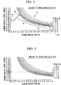
- Fig. 4 shows a graph illustrating the design of the wind turbine blade 1 according to this embodiment.
- the horizontal axis indicates the dimensionless radius
- the vertical axis indicates the dimensionless chord length.
- the dimensionless radius as described above, is the radial position r of the blade section from the center of rotation divided by the blade radius R of the wind turbine blade 1 (r/R).
- the blade radius is half the diameter (blade diameter) of a locus circle traced by the blade tip when the wind turbine blade 1 rotates.
- the dimensionless chord length is the chord length c of the blade section divided by the blade radius R (c/R).
- Fig. 4 shows a plurality of curves (thin lines) with constant design lift coefficient CLdesign obtained by equation (3) above.
- a curve with constant design lift coefficient satisfies equation (3) above and therefore gives the optimum chord length (vertical axis) at the particular design tip speed ratio in terms of aerodynamic characteristics.
- the design tip speed ratio is 8.0 to 8.5, and the Reynolds number is 3,000,000 to 10,000,000.
- the wind turbine blade 1 includes a blade body 3 whose chord length increases from the blade tip 1b toward the blade root 1a.
- the dimensionless radius of the blade body 3 is 0.2 to 0.95.
- the blade body 3 includes a blade tip region 1c located near the blade tip 1b and whose chord length increases gradually, a maximum-chord-length position 1d located near the blade root 1a and having the maximum chord length, and a transition region 1e located between the blade tip region 1c and the maximum-chord-length position 1d.
- the dimensionless radius of the blade tip region 1c is 0.5 to 0.95
- the dimensionless radius of the maximum-chord-length position 1d is (0.25 ⁇ 0.05)
- the dimensionless radius of the transition region 1e is from 0.2 (excluding 0.2) to less than 0.5.
- the blade tip region 1c has a substantially constant first design lift coefficient (in this embodiment, 1.15).
- the first design lift coefficient of the blade tip region 1c is set to a practical upper limit feasible in terms of the thickness ratio (e.g., about 18%) of the blade tip region 1c, which is a thin portion.
- a higher design lift coefficient which is preferred in terms of aerodynamic characteristics, can be achieved by increasing the curvature, although an increased curvature can result in flow separation and therefore higher loss as an exclusive event; therefore, the design lift coefficient is limited to a certain value.
- the blade tip region 1c which receives a larger wind force and therefore produces a higher output power, delivers the desired aerodynamic characteristics.
- the maximum-chord-length position 1d has a second design lift coefficient (in this embodiment, 1.45) higher than the first design lift coefficient.
- the second design lift coefficient is determined from the maximum chord length, which is limited for reasons such as transportation. For example, as shown in Fig. 4 , if the dimensionless maximum chord length is limited to 0.08 by factors such as the width of the roads where the wind turbine blade 1 is transported, the design lift coefficient for that dimensionless maximum chord length is determined to be 1.45 from the dimensionless radius (0.25 ⁇ 0.05) of the maximum-chord-length position 1d.
- the transition region 1e has a design lift coefficient increasing gradually from the first design lift coefficient (1.15) to the second design lift coefficient (1.45). That is, the blade root side of the blade tip region 1c, which has the first design lift coefficient, is smoothly connected to the maximum-chord-length position 1d, which has the second design lift coefficient. This allows for a reduced range of variation in design lift coefficient if the chord length is increased from the blade tip region 1c to the maximum-chord-length position 1d, thus avoiding a substantial loss of aerodynamic performance.
- the desired aerodynamic characteristics can also be maintained at the thick portion (the portion thicker than the blade tip region 1c, which is the region extending from the transition region 1e to the maximum-chord-length position 1d), which has not been taken into account in the related art.
- Figs. 5 and 6 are graphs used for designing the wind turbine blade 1 shown in Fig. 4 ; therefore, they have the same vertical and horizontal axes and show the same design lift coefficient CLdesign curves as Fig. 4 .
- the dimensionless chord length satisfying the desired design lift coefficient is determined by equation (3).
- the dimensionless chord length that gives a desired design lift coefficient of 1.15 at a dimensionless radial position of 0.6 is 0.04.
- chord length at the maximum-chord-length position (at a dimensionless radial position of about 0.2 to 0.3; in this embodiment, 0.24) 1d is specified at a predetermined maximum value (a dimensionless chord length of about 0.065 to 0.085; in this embodiment, 0.08) for reasons such as transportation. Accordingly, the design lift coefficient at the maximum-chord-length position 1d (second design lift coefficient) is determined (in this embodiment, 1.45).
- chord length near the blade tip (at a dimensionless radial position of about 0.85 to 0.95) is specified at the practical upper limit of the design lift coefficient (in this embodiment, about 1.15 for a thin portion having a thickness ratio of about 18%; first design lift coefficient).
- the design chord length is specified using a smooth line joining the points determined in steps 1 and 2. More specifically, the dimensionless chord length of the blade tip region 1c, where the dimensionless radial position is 0.5 to 0.95, is specified along the curve at a CLdesign of 1.15 so that the design lift coefficient determined in step 2 is maintained.
- combinations of dimensionless radial positions and design lift coefficients of the blade body 3 of the wind turbine blade 1 are specified.
- the solid line shown in Fig. 6 indicates the median dimensionless chord length; in practice, the dimensionless chord length is specified within a predetermined range at each dimensionless radius, and the range is specified within the frame 5 in Fig. 6 .
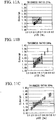
- Figs. 7A, 7B, and 7C show distributions of the design lift coefficient against the dimensionless radial position for the wind turbine blade 1 having the profile defined as above.
- the first design lift coefficient of the blade tip region 1c where the dimensionless radial position is 0.5 to 0.95, is X ⁇ 0.10, where X is the median.
- the second design lift coefficient of the maximum-chord-length position 1d, where the dimensionless radial position is (0.25 ⁇ 0.05), is X+0.3 ⁇ 0.2.
- the design lift coefficient of the transition region 1e, where the dimensionless radial position is from 0.2 (excluding 0.2) to less than 0.5, at the central position (in the figure, at a dimensionless radius of 0.35) between the end of the blade tip region 1c facing the blade root (at a dimensionless radius of 0.5) and the maximum-chord-length position 1d is X+0.15 ⁇ 0.15.
- Fig. 7B shows an example where the range of design lift coefficients is narrower than in Fig. 7A .
- the first design lift coefficient of the blade tip region 1c where the dimensionless radial position is 0.5 to 0.95, is X ⁇ 0.05, where X is the median.
- the second design lift coefficient of the maximum-chord-length position 1d, where the dimensionless radial position is (0.25 ⁇ 0.05), is X+0.3 ⁇ 0.1.
- the design lift coefficient of the transition region 1e, where the dimensionless radial position is from 0.2 (excluding 0.2) to less than 0.5, at the central position (in the figure, at a dimensionless radius of 0.35) between the end of the blade tip region 1c facing the blade root (at a dimensionless radius of 0.5) and the maximum-chord-length position 1d is X+0.15 ⁇ 0.075.
- Fig. 7C shows an example where specific design lift coefficients are applied. Specifically, the first design lift coefficient of the blade tip region 1c, where the dimensionless radial position is 0.5 to 0.95, is 1.15 ⁇ 0.05.
- the design lift coefficient of the transition region 1e, where the dimensionless radial position is from 0.2 (excluding 0.2) to less than 0.5, at the central position (in the figure, at a dimensionless radius of 0.35) between the end of the blade tip region 1c facing the blade root (at a dimensionless radius of 0.5) and the maximum-chord-length position 1d is 1.30 ⁇ 0.075.
- Figs. 8A, 8B, and 8C show distributions of the design lift coefficient against the thickness ratio for the wind turbine blade 1 having the profile defined as in Figs. 4 to 6 .
- the horizontal axes in Figs. 7A, 7B, and 7C indicate the dimensionless radius
- the horizontal axes in Figs. 8A, 8B, and 8C indicate the thickness ratio.
- the thickness ratio is the percentage obtained by dividing the maximum thickness by the chord length.
- the first design lift coefficient of the blade tip region 1c is X ⁇ 0.10, where X is the median.
- the second design lift coefficient of the maximum-chord-length position 1d, where the thickness ratio is 42%, is X+0.3 ⁇ 0.2.
- the design lift coefficient of the transition region 1e, where the dimensionless radial position is from 30% (excluding 30%) to less than 42%, at the central position (in the figure, at a thickness ratio of 36%) between the end of the blade tip region 1c facing the blade root (at a thickness ratio of 30%) and the maximum-chord-length position 1d is X+0.15 ⁇ 0.15.
- Fig. 8B shows an example where the range of design lift coefficients is narrower than in Fig. 8A .
- the first design lift coefficient of the blade tip region 1c where the thickness ratio is 12% to 30%, is X ⁇ 0.05, where X is the median.
- the second design lift coefficient of the maximum-chord-length position 1d, where the thickness ratio is 42%, is X+0.3 ⁇ 0.1.
- the design lift coefficient of the transition region 1e, where the thickness ratio is from 30% (excluding 30%) to less than 42%, at the central position (in the figure, at a thickness ratio of 36%) between the end of the blade tip region 1c facing the blade root (at a thickness ratio of 30%) and the maximum-chord-length position 1d is X+0.15 ⁇ 0.075.
- Fig. 8C shows an example where specific design lift coefficients are applied. Specifically, the first design lift coefficient of the blade tip region 1c, where the thickness ratio is 12% to 30%, is 1.15 ⁇ 0.05.
- the second design lift coefficient of the maximum-chord-length position 1d, where the thickness ratio is 42%, is 1.45 ⁇ 0.1.
- the design lift coefficient of the transition region 1e, where the thickness ratio is from 30% (excluding 30%) to less than 42%, at the central position (in the figure, at a thickness ratio of 36%) between the end of the blade tip region 1c facing the blade root (at a thickness ratio of 30%) and the maximum-chord-length position 1d is 1.30 ⁇ 0.075.
- Y125 which indicates the distance between the suction side and the chord (blade chord) at the leading edge, is determined (Y125-determining step) to define the airfoil shape at each thickness position.
- Y125 is the percentage obtained by dividing the distance from the chord on the suction side, at a 1.25% position, by the chord length, where the position of the leading edge along the chord length is defined as 0% and the position of the trailing edge along the chord length is defined as 100%.
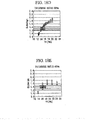
- Figs. 10A, 10B, and 10C show distributions of Y125 against the thickness ratio.
- Y125 in Figs. 10A, 10B, and 10C is specified as in the following table.
- Table 1 ⁇ Thickness ratio 1 42% 1 36% 30% 24% 21% 18% (a) 3.4 ⁇ 0.6 3.0 ⁇ 0.40 27.5 ⁇ 0.25 2.6 ⁇ 0.15 2.575 ⁇ 0.13 2.55 ⁇ 0.1 (b) 3.4 ⁇ 0.4 3.0 ⁇ 0.25 27.5 ⁇ 0.20 2.6 ⁇ 0.15 2.575 ⁇ 0.13 2.55 ⁇ 0.1 (c) 3.4 ⁇ 0.2 3.0 ⁇ 0.20 27.5 ⁇ 0.15 2.6 ⁇ 0.15 2.575 ⁇ 0.13 2.55 ⁇ 0.1
- Y125 is specified within the ranges in (a), preferably within the ranges in (b), and more preferably within the ranges in (c).
- Y125 of the wind turbine blade 1 at each blade section is determined by an interpolation curve passing through Y125 at each thickness ratio in the above table.
- Figs. 10A, 10B, and 10C plot, as squares, the values of Y125 of a wind turbine blade based on an NACA blade in the related art as an example for comparison with this embodiment.
- the wind turbine blade according to this embodiment has different Y125 from the wind turbine blade in the related art.
- Figs. 11A to 11E show data that provides evidence that Y125 gives the desired design lift coefficient.
- Figs. 11A to 11E show results for thickness ratios of 21%, 24%, 30%, 36%, and 42%, respectively. These figures are obtained by numerical simulations with varying Y125.
- a blade section having a higher maximum lift coefficient, a higher maximum lift-to-drag ratio, and a smaller turbulent boundary layer thickness at the trailing edge, as well as the optimum design lift coefficient determined as above.
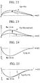
- Fig. 12 shows an airfoil according to this embodiment.
- the airfoil shape is normalized with respect to a chord length C, i.e., the length from a leading edge 6 to a trailing edge 4 on a chord line 7, in a blade element section at each thickness ratio of the wind turbine blade 1.
- ⁇ indicates the wind inflow angle
- CD indicates the drag coefficient
- CL indicates the lift coefficient
- a turbulent boundary layer 5 forms on the suction side from a maximum-thickness position 2 to the trailing edge 4.
- the turbulent boundary layer 5 releases boundary layer vortices, which cause aerodynamic noise. Accordingly, the aerodynamic noise can be reduced by reducing the turbulent boundary layer thickness DSTAR at the trailing edge 4.
- the airfoil shown in the figure is provided in a range of thickness ratios of 12% to 21%.
- This thickness ratio range is defined as the range that functions as the main portion for converting wind force to the rotation of the wind turbine blade.
- the maximum-thickness position 2 is provided in a range of chordwise positions X/C of 0.28 to 0.32 (more preferably, 0.29 to 0.31).
- the maximum-camber position which has the maximum camber, is provided in a range of chordwise positions X/C of 0.45 to 0.55.
- the camber distribution is substantially symmetrical with respect to the maximum-camber position in the chordwise direction.
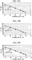
- Figs. 13A to 13D show parameters characterizing the performance of the wind turbine blade with respect to the wind inflow angle ⁇ .
- Fig. 13A shows changes in lift coefficient CL against the wind inflow angle ⁇ .
- the lift coefficient CL increases with increasing wind inflow angle ⁇ and decreases after reaching the maximum, i.e., the maximum lift coefficient CLmax.
- the maximum lift coefficient CLmax is related to improvements in performance at high wind speeds and prevention of stalling, which results from, for example, fluctuations and disturbances in the incoming wind, and a higher maximum lift coefficient CLmax is desirable.
- the maximum lift coefficient CLmax is also a parameter that affects the blade aerodynamic performance during the transition state after the wind turbine reaches the maximum rotational speed and before it reaches the rated output power. As shown in the figure, a higher design lift coefficient CLdesign is desirable for slender blades, such as those of large wind turbines, to deliver high performance.
- Fig. 13B shows changes in lift-to-drag ratio against the wind inflow angle ⁇ .
- the lift-to-drag ratio L/D increases with increasing wind inflow angle ⁇ and decreases after reaching the maximum lift-to-drag ratio L/Dmax.
- the maximum lift-to-drag ratio L/Dmax is a parameter that affects the blade aerodynamic performance during variable-speed operation of the wind turbine (design point), and a higher lift-to-drag ratio L/D is desirable.
- Fig. 13C shows changes in transition position XTR against the wind inflow angle ⁇ .
- the transition position XTR is located substantially in the center of the blade chord at small wind inflow angles ⁇ and shifts toward the leading edge (L.E.) above a certain wind inflow angle ⁇ . This means that the roughness characteristics and the stall characteristics are improved by shifting the transition position XTR forward (toward the leading edge).
- Fig. 13D shows changes in the boundary layer thickness (displacement thickness) DSTAR at the trailing edge against the wind inflow angle ⁇ .
- the boundary layer thickness DSTAR increases with increasing wind inflow angle ⁇ .
- a smaller wind inflow angle ⁇ is desirable because it is the main factor in aerodynamic noise.
- the maximum-thickness position is preferably provided in a range of chordwise positions X/C of 0.28 to 0.32 (more preferably, 0.29 to 0.31).
- the maximum-camber position is preferably provided in a range of chordwise positions X/C of 0.45 to 0.55 so that the camber is midway between forward and backward cambers.
- the camber distribution is preferably substantially symmetrical with respect to the maximum-camber position in the chordwise direction.
- Figs. 14A and 14B show the basis for why the chordwise position X/C of the maximum-thickness position is 0.28 to 0.32 (more preferably, 0.29 to 0.31). These figures plot results obtained by numerical simulations under a plurality of conditions. As shown in Fig. 4 , the chordwise position X/C at least needs to be 32% (0.32) or less to ensure a high range of design lift coefficients CLdesign, i.e., 1.15 ⁇ 0.05. In addition, the chordwise position X/C is preferably located as far forward as possible because the boundary layer thickness DSTAR tends to be smaller (the noise is lower) as the maximum-thickness position is located farther forward.
- the lower limit of the chordwise position X/C is preferably 0.28.
- Figs. 15A and 15B show the basis for why the chordwise position X/C of the maximum-camber position is preferably 0.45 to 0.55 and why the camber distribution is preferably substantially symmetrical with respect to the maximum-camber position in the chordwise direction.
- FIG. 15A shows that the maximum lift coefficient CLmax increases as the maximum-camber position is shifted away from the trailing edge toward the leading edge. That is, a forward camber is preferred in terms of maximum lift coefficient CLmax.
- Fig. 15B shows that the maximum lift-to-drag ratio L/Dmax increases as the maximum-camber position is shifted away from the leading edge toward the trailing edge.
- chordwise position X/C of the maximum-camber position is preferably midway, i.e., 0.45 to 0.55 (preferably, 0.5).
- this embodiment provides the following advantageous effects.
- the wind turbine blade 1 can deliver the desired aerodynamic characteristics under conditions where the upper limit of the chord length near the blade root is limited.
- the aerodynamic performance of the thick portion located closer to the blade root than to the blade tip region 1c can be improved.
- Y125 which correlates with the design lift coefficient
- a blade profile having the desired design lift coefficients can be determined.
- a slender blade with high design lift coefficients can be provided, and therefore, the load on the wind turbine blade can be reduced. This allows the design of a longer wind turbine blade, which results in a higher level of electricity generation.
- the maximum-camber position is located in the center in the chordwise direction, and the camber distribution is symmetrical with respect to the maximum-camber position in the chordwise direction, a wind turbine blade with high performance and low noise can be provided.
- This embodiment differs from the first embodiment in that whereas the first embodiment determines Y125, which indicates the distance between the suction side and the chord (blade chord) at the leading edge, this embodiment determines the blade profile using the suction-side convexity YS of the blade.
- the other points are similar to those of the first embodiment; therefore, a description thereof is omitted.
- the suction-side convexity YS of the blade is determined (YS-determining step) to define the airfoil shape at each thickness position.
- YS as shown in Fig. 16 , is the percentage obtained by dividing the distance from the chord (blade chord) on the suction side, at the maximum-thickness position, by the chord length.
- Figs. 17A, 17B, and 17C show distributions of the suction-side convexity YS against the thickness ratio.
- YS in Figs. 17A, 17B, and 17C is specified as in the following table.
- Table 3 ⁇ Thickness ratio 42% 36% 30% 24% 21% 18% (a) 16.6 ⁇ 3.0 14.6 ⁇ 2.0 13.3 ⁇ 1.2 12.3 ⁇ 0.7 12.0 ⁇ 0.6 11.7 ⁇ 0.5 (b) 16.6 ⁇ 2.0 14.6 ⁇ 1.2 13.3 ⁇ 1.0 12.3 ⁇ 0.7 12.0 ⁇ 0.6 11.7 ⁇ 0.5 (c) 16.6 ⁇ 1.5 14.6 ⁇ 1.0 13.3 ⁇ 0.8 12.3 ⁇ 0.7 12.0 ⁇ 0.6 11.7 ⁇ 0.5
- the suction-side convexity YS is specified within the ranges in (a), preferably within the ranges in (b), and more preferably within the ranges in (c).
- the suction-side convexity YS of the wind turbine blade 1 at each blade section is determined by an interpolation curve passing through the suction-side convexity YS at each thickness ratio in the above table.
- Figs. 17A, 17B, and 17C plot, as squares, the suction-side convexities YS of a wind turbine blade based on an NACA blade in the related art as an example for comparison with this embodiment.
- the wind turbine blade according to this embodiment has different suction-side convexities YS from the wind turbine blade in the related art.
- Figs. 18A to 18E show data that provides evidence that the suction-side convexity YS gives the desired design lift coefficient.
- Figs. 18A to 18E show results for thickness ratios of 21%, 24%, 30%, 36%, and 42%, respectively. These figures are obtained by numerical simulations with varying suction-side convexities YS.
- this embodiment provides the following advantageous effect.
- a blade profile having the desired design lift coefficients can be determined.
- a slender blade with high design lift coefficients can be provided, and therefore, the load on the wind turbine blade can be reduced. This allows the design of a longer wind turbine blade, which results in a higher level of electricity generation.
- This embodiment differs from the second embodiment in that whereas the second embodiment determines the blade profile using the suction-side convexity YS, this embodiment determines the blade profile using the pressure-side convexity YP.
- the other points are similar to those of the first embodiment; therefore, a description thereof is omitted.
- the pressure-side convexity YP of the blade is determined (YP-determining step) to define the airfoil shape at each thickness position.
- YP is the percentage obtained by dividing the distance from the chord (blade chord) on the pressure side, at the maximum-thickness position, by the chord length.
- Figs. 19A, 19B, and 19C show distributions of the pressure-side convexity YP against the thickness ratio.
- YP in Figs. 19A, 19B, and 19C is specified as in the following table.
- Table 4 ⁇ Thickness ratio 42% 36% 30% 24% 21% 18% (a) 25.4 ⁇ 3.0 21.4 ⁇ 2.0 16.7 ⁇ 1.2 11.7 ⁇ 0.7 9.0 ⁇ 0.6 6.3 ⁇ 0.5 (b) 25.4 ⁇ 2.0 21.4 ⁇ 1.2 16.7 ⁇ 1.0 11.7 ⁇ 0.7 9 ⁇ 0 ⁇ 0.6 6.3 ⁇ 0.5 (c) 25.4 ⁇ 1.5 21.4 ⁇ 1.0 16.7 ⁇ 0.8 11.7 ⁇ 0.7 9.0 ⁇ 0.6 6.3 ⁇ 0.5
- the pressure-side convexity YP is specified within the ranges in (a), preferably within the ranges in (b), and more preferably within the ranges in (c).
- the pressure-side convexity YP of the wind turbine blade 1 at each blade section is determined by an interpolation curve passing through the pressure-side convexity YP at each thickness ratio in the above table.
- Figs. 19A, 19B, and 19C plot, as squares, the pressure-side convexities YP of a wind turbine blade based on an NACA blade in the related art as an example for comparison with this embodiment.
- the wind turbine blade according to this embodiment has different pressure-side convexities YP from the wind turbine blade in the related art.
- Figs. 20A to 20E show data that provides evidence that the pressure-side convexity YP gives the desired design lift coefficient.
- Figs. 20A to 20E show results for thickness ratios of 21%, 24%, 30%, 36%, and 42%, respectively. These figures are obtained by numerical simulations with varying pressure-side convexities YP.
- this embodiment provides the following advantageous effect.
- a blade profile having the desired design lift coefficients can be determined.
- a slender blade with high design lift coefficients can be provided, and therefore, the load on the wind turbine blade can be reduced. This allows the design of a longer wind turbine blade, which results in a higher level of electricity generation.
- Figs. 21A to 21D show the effects provided by the first to third embodiments described above.
- blade A is a reference blade used for comparison, whose design lift coefficient is about 0.8 at the blade tip and is not optimized in the lengthwise (radial) direction
- blade B is a blade whose design lift coefficient is 40% higher than that of blade A
- blade C is a blade corresponding to the embodiments, whose design lift coefficient is the same as that of blade B and is optimized in the lengthwise (radial) direction.
- Blade C whose design lift coefficient is optimized in the lengthwise direction, has a 2% higher blade efficiency than blade B and thus generates 1% more electricity than blade B (7.5% more electricity than blade A), as shown in Fig. 21D .
- the wind turbine blade of the present invention is not limited thereto; any interpolation curve passing through the suction-side convexities YS or pressure-side convexities YP shown in Table 1 or 2 at thickness ratios of 21% to 35% may be used. This is because the characteristics of a wind turbine blade are primarily determined in this thickness ratio range.
- the design tip speed ratio is 8.0 to 8.5 in the embodiments described above, the present invention is not limited thereto; it can also be applied to a design tip speed ratio of, for example, 6.0 to 9.0.
- the blade tip region 1c, the transition region 1e, and the maximum-chord-length position are not limited to the ranges of dimensionless radial positions or thickness ratios illustrated in the embodiments; they can be changed as long as the advantages of the present invention are provided.
- This embodiment differs from the embodiments described above in that the suction-side profile or the thickness distribution at each radial position (each thickness ratio) is specified such that it is extended or contracted in the Y direction.
- the other points are similar to those of the first embodiment; therefore, a description thereof is omitted.
- a method for specifying the profile of the wind turbine blade 1 having the desired design lift coefficient at each thickness position (or radial position) after the desired design lift coefficient is determined as in Fig. 8C (design-lift-coefficient determining step) will be described.
- This embodiment is particularly effective in defining the airfoil profile (blade section profile) at each thickness position such that it has substantially the same design lift coefficient.
- the airfoil profile (blade section profile) of the blade body 3 at each thickness position (radial position) is specified such that the airfoil profile has a suction-side profile that is extended or contracted in the Y direction.
- Fig. 22 illustrates a method for determining the suction-side profile.
- the horizontal axis indicates the chordwise position X/C, which is the distance from the leading edge normalized by dividing it by the chord length C
- the vertical axis is a coordinate Y u , which is the distance from the chord line (horizontal axis) normalized by dividing it by the chord length C.
- Figs. 23 to 25 described later, use coordinate systems normalized by dividing them by the chord length C, as does Fig. 22 .
- a suction-side profile specified by a suction surface coordinate (the distance between the chord position and the suction-side profile) Y u1 is a reference suction-side profile
- the airfoil profile (blade section profile) at each thickness position has a suction-side profile that is extended or contracted in the Y direction, a blade profile that delivers comparable aerodynamic performance to the reference suction-side profile can be defined at each thickness position.
- Fig. 23 illustrates a method for determining the thickness distribution.
- the airfoil profile (blade section profile) of the blade body 3 at each thickness position (radial position) is specified such that the airfoil profile has a thickness distribution that is extended or contracted in the Y direction. Specifically, as shown in Fig.
- the airfoil profile (blade section profile) at each thickness position has a thickness distribution that is extended or contracted in the Y direction, a blade profile that delivers comparable aerodynamic performance to the reference thickness distribution can be defined at each thickness position.
- Fig. 24 illustrates a method for determining the pressure-side profile of an airfoil profile (blade section profile).
- a blade profile that delivers comparable aerodynamic performance to the reference suction-side profile can be defined at each thickness position.
- the trailing edge portion extending from the maximum-thickness position to the trailing edge may have a pressure-side profile determined by equation (6) above.
- the trailing edge portion may have a pressure-side profile defined by adding a predetermined amount of adjustment to the pressure-side profile determined by equation (6) above, which serves as a reference pressure-side profile. This is because the pressure-side profile of the trailing edge portion does not greatly affect the continuity of the airfoil profile (blade section profile). Accordingly, relatively high design flexibility is permitted for the pressure-side profile of the trailing edge portion.
- the pressure-side profile of the trailing edge portion can be set to any profile to optimize the design lift coefficient.
- the amount of adjustment Y s can be determined by a quartic function of the chord position x, where the amount of adjustment Y s is 0 at the maximum-thickness position and the trailing edge, and where the first differential of the pressure surface coordinate that gives the pressure-side profile in the chordwise direction is 0.
- the amount of adjustment Y s can be obtained in a simple manner, and therefore, the desired pressure-side profile can be easily determined.
- airfoil profiles (blade section profiles) having the desired design lift coefficients can be determined in the radial direction of the wind turbine blade, which improves the performance of the wind turbine blade.
Applications Claiming Priority (8)
| Application Number | Priority Date | Filing Date | Title |
|---|---|---|---|
| JP2010238039A JP5574915B2 (ja) | 2010-10-22 | 2010-10-22 | 風車翼およびこれを備えた風力発電装置ならびに風車翼の設計方法 |
| JP2010238042A JP5675270B2 (ja) | 2010-10-22 | 2010-10-22 | 風車翼およびこれを備えた風力発電装置ならびに風車翼の設計方法 |
| JP2010238043A JP5433554B2 (ja) | 2010-10-22 | 2010-10-22 | 風車翼およびこれを備えた風力発電装置ならびに風車翼の設計方法 |
| JP2010238038A JP5574914B2 (ja) | 2010-10-22 | 2010-10-22 | 風車翼およびこれを備えた風力発電装置ならびに風車翼の設計方法 |
| JP2010238040A JP5433553B2 (ja) | 2010-10-22 | 2010-10-22 | 風車翼およびこれを備えた風力発電装置ならびに風車翼の設計方法 |
| EP11834441.5A EP2631474B1 (de) | 2010-10-22 | 2011-10-20 | Windturbinenblatt, windturbinengenerator damit und entwurfsverfahren dafür |
| EP16198195.6A EP3179094B1 (de) | 2010-10-22 | 2011-10-20 | Windturbinenblatt, windturbinengenerator damit und entwurfsverfahren dafür |
| PCT/JP2011/074176 WO2012053602A1 (ja) | 2010-10-22 | 2011-10-20 | 風車翼およびこれを備えた風力発電装置ならびに風車翼の設計方法 |
Related Parent Applications (3)
| Application Number | Title | Priority Date | Filing Date |
|---|---|---|---|
| EP11834441.5A Division EP2631474B1 (de) | 2010-10-22 | 2011-10-20 | Windturbinenblatt, windturbinengenerator damit und entwurfsverfahren dafür |
| EP16198195.6A Division-Into EP3179094B1 (de) | 2010-10-22 | 2011-10-20 | Windturbinenblatt, windturbinengenerator damit und entwurfsverfahren dafür |
| EP16198195.6A Division EP3179094B1 (de) | 2010-10-22 | 2011-10-20 | Windturbinenblatt, windturbinengenerator damit und entwurfsverfahren dafür |
Publications (2)
| Publication Number | Publication Date |
|---|---|
| EP3343024A1 true EP3343024A1 (de) | 2018-07-04 |
| EP3343024B1 EP3343024B1 (de) | 2019-05-22 |
Family
ID=45975312
Family Applications (4)
| Application Number | Title | Priority Date | Filing Date |
|---|---|---|---|
| EP16198206.1A Active EP3179095B1 (de) | 2010-10-22 | 2011-10-20 | Windturbinenblatt, windturbinengenerator damit und entwurfsverfahren dafür |
| EP11834441.5A Active EP2631474B1 (de) | 2010-10-22 | 2011-10-20 | Windturbinenblatt, windturbinengenerator damit und entwurfsverfahren dafür |
| EP16198195.6A Revoked EP3179094B1 (de) | 2010-10-22 | 2011-10-20 | Windturbinenblatt, windturbinengenerator damit und entwurfsverfahren dafür |
| EP18152981.9A Revoked EP3343024B1 (de) | 2010-10-22 | 2011-10-20 | Windturbinenblatt, windturbinengenerator damit und entwurfsverfahren dafür |
Family Applications Before (3)
| Application Number | Title | Priority Date | Filing Date |
|---|---|---|---|
| EP16198206.1A Active EP3179095B1 (de) | 2010-10-22 | 2011-10-20 | Windturbinenblatt, windturbinengenerator damit und entwurfsverfahren dafür |
| EP11834441.5A Active EP2631474B1 (de) | 2010-10-22 | 2011-10-20 | Windturbinenblatt, windturbinengenerator damit und entwurfsverfahren dafür |
| EP16198195.6A Revoked EP3179094B1 (de) | 2010-10-22 | 2011-10-20 | Windturbinenblatt, windturbinengenerator damit und entwurfsverfahren dafür |
Country Status (5)
| Country | Link |
|---|---|
| US (1) | US9790795B2 (de) |
| EP (4) | EP3179095B1 (de) |
| KR (1) | KR20130041263A (de) |
| CN (3) | CN103080541B (de) |
| WO (1) | WO2012053602A1 (de) |
Cited By (3)
| Publication number | Priority date | Publication date | Assignee | Title |
|---|---|---|---|---|
| DE102019119027A1 (de) * | 2019-07-12 | 2021-01-14 | Wobben Properties Gmbh | Rotorblatt und Windenergieanlage |
| KR20210023541A (ko) | 2019-08-23 | 2021-03-04 | 두산중공업 주식회사 | 베인과 이를 포함하는 압축기 및 가스 터빈 |
| KR20220015700A (ko) | 2020-07-31 | 2022-02-08 | 두산중공업 주식회사 | 블레이드와 이를 포함하는 압축기 및 가스 터빈 |
Families Citing this family (13)
| Publication number | Priority date | Publication date | Assignee | Title |
|---|---|---|---|---|
| CN102322407B (zh) * | 2011-08-30 | 2013-06-12 | 重庆大学 | 风力机叶片气动外形协同设计方法 |
| CO6860304A1 (es) | 2012-07-13 | 2014-02-10 | Univ Pontificia Bolivariana | Descripción geometrica pala para rotor |
| KR101454260B1 (ko) * | 2013-05-14 | 2014-10-27 | 한국전력공사 | 두께비 35%의 대용량 풍력터빈 블레이드용 에어포일 |
| KR101454261B1 (ko) * | 2013-05-14 | 2014-10-27 | 한국전력공사 | 두께비 40%의 대용량 풍력터빈 블레이드용 에어포일 |
| KR101454259B1 (ko) * | 2013-05-14 | 2014-10-27 | 한국전력공사 | 두께비 30%의 대용량 풍력터빈 블레이드용 에어포일 |
| KR101445106B1 (ko) * | 2013-06-07 | 2014-10-01 | 주식회사 휴먼컴퍼지트 | 풍력 발전기용 블레이드 40% 익형 |
| CN103557122B (zh) * | 2013-07-24 | 2015-12-23 | 李英吉 | 一种10kW风电机组叶片 |
| DE102015012427A1 (de) * | 2015-09-25 | 2017-03-30 | Senvion Gmbh | Rotorblatt mit einem schalloptimierten Profil sowie Verfahren zum Herstellen eines Rotorblatts |
| CN105781905A (zh) * | 2016-03-29 | 2016-07-20 | 西北工业大学 | 一种具有低粗糙度敏感性和高升阻特性的风力机翼型 |
| JP6783212B2 (ja) * | 2017-10-20 | 2020-11-11 | 三菱重工業株式会社 | 風車翼へのボルテックスジェネレータの配置位置決定方法、風車翼アセンブリの製造方法及び風車翼アセンブリ |
| US11781522B2 (en) | 2018-09-17 | 2023-10-10 | General Electric Company | Wind turbine rotor blade assembly for reduced noise |
| CN109899229A (zh) * | 2019-03-27 | 2019-06-18 | 上海电力学院 | 一种低风速高性能风力机叶片 |
| US20230235721A1 (en) * | 2020-06-29 | 2023-07-27 | Vestas Wind Systems A/S | A wind turbine |
Citations (4)
| Publication number | Priority date | Publication date | Assignee | Title |
|---|---|---|---|---|
| EP0675285A1 (de) * | 1994-03-14 | 1995-10-04 | Midwest Research Institute | Blattprofil für windturbine |
| US5474425A (en) * | 1992-03-18 | 1995-12-12 | Advanced Wind Turbines, Inc. | Wind turbine rotor blade |
| EP1152148A1 (de) | 2000-05-01 | 2001-11-07 | Enron Wind Energy Systems Co. | Rotorblattprofile für Windenergieanlagen |
| WO2007010329A1 (en) | 2005-07-15 | 2007-01-25 | Vestas Wind Systems A/S | Wind turbine blade |
Family Cites Families (17)
| Publication number | Priority date | Publication date | Assignee | Title |
|---|---|---|---|---|
| GB647159A (en) * | 1946-09-16 | 1950-12-06 | Maurice Adolph Garbell | Improvements in or relating to a lifting surface and method of designing same |
| US4519746A (en) * | 1981-07-24 | 1985-05-28 | United Technologies Corporation | Airfoil blade |
| EP0113466B1 (de) * | 1982-12-30 | 1988-11-30 | The Boeing Company | Flügel mit verjüngter relativer Profildicke |
| US4611773A (en) * | 1982-12-30 | 1986-09-16 | The Boeing Company | Tapered thickness-chord ratio wing |
| FR2590229B1 (fr) * | 1985-11-19 | 1988-01-29 | Onera (Off Nat Aerospatiale) | Perfectionnements apportes aux helices aeriennes en ce qui concerne le profil de leurs pales |
| US5417548A (en) | 1994-01-14 | 1995-05-23 | Midwest Research Institute | Root region airfoil for wind turbine |
| AU2003237707B2 (en) | 2002-06-05 | 2008-01-10 | Aloys Wobben | Rotor blade for a wind power plant |
| DE10307682A1 (de) | 2002-06-05 | 2004-01-08 | Aloys Wobben | Rotorblatt einer Windenergieanlage |
| JP3935804B2 (ja) | 2002-08-26 | 2007-06-27 | 三菱重工業株式会社 | 翼及びこれを備える風力発電装置 |
| DE10319246A1 (de) | 2003-04-28 | 2004-12-16 | Aloys Wobben | Rotorblatt einer Windenergieanlage |
| US7883324B2 (en) | 2007-01-09 | 2011-02-08 | General Electric Company | Wind turbine airfoil family |
| US8197218B2 (en) | 2007-11-08 | 2012-06-12 | Alliance For Sustainable Energy, Llc | Quiet airfoils for small and large wind turbines |
| DE102008052858B9 (de) * | 2008-10-23 | 2014-06-12 | Senvion Se | Profil eines Rotorblatts und Rotorblatt einer Windenergieanlage |
| US8241000B2 (en) * | 2009-06-16 | 2012-08-14 | Heartland Energy Solutions, LLC. | Wind turbine rotor blade and airfoil section |
| CN101615216B (zh) * | 2009-07-28 | 2011-01-05 | 重庆大学 | 对翼型尾缘进行流线形增厚的方法 |
| DK3835571T3 (da) * | 2010-07-16 | 2023-12-04 | Lm Wind Power As | Vindmøllevinge med smal skulder og relative tykke bæreplansprofiler |
| JP5479388B2 (ja) * | 2011-02-28 | 2014-04-23 | 三菱重工業株式会社 | 風車翼およびこれを備えた風力発電装置 |
-
2011
- 2011-10-20 KR KR1020137004629A patent/KR20130041263A/ko not_active Application Discontinuation
- 2011-10-20 CN CN201180042131.0A patent/CN103080541B/zh active Active
- 2011-10-20 CN CN201510243491.7A patent/CN104929866B/zh active Active
- 2011-10-20 EP EP16198206.1A patent/EP3179095B1/de active Active
- 2011-10-20 US US13/825,912 patent/US9790795B2/en active Active
- 2011-10-20 EP EP11834441.5A patent/EP2631474B1/de active Active
- 2011-10-20 CN CN201510242071.7A patent/CN104929865B/zh active Active
- 2011-10-20 WO PCT/JP2011/074176 patent/WO2012053602A1/ja active Application Filing
- 2011-10-20 EP EP16198195.6A patent/EP3179094B1/de not_active Revoked
- 2011-10-20 EP EP18152981.9A patent/EP3343024B1/de not_active Revoked
Patent Citations (4)
| Publication number | Priority date | Publication date | Assignee | Title |
|---|---|---|---|---|
| US5474425A (en) * | 1992-03-18 | 1995-12-12 | Advanced Wind Turbines, Inc. | Wind turbine rotor blade |
| EP0675285A1 (de) * | 1994-03-14 | 1995-10-04 | Midwest Research Institute | Blattprofil für windturbine |
| EP1152148A1 (de) | 2000-05-01 | 2001-11-07 | Enron Wind Energy Systems Co. | Rotorblattprofile für Windenergieanlagen |
| WO2007010329A1 (en) | 2005-07-15 | 2007-01-25 | Vestas Wind Systems A/S | Wind turbine blade |
Non-Patent Citations (1)
| Title |
|---|
| "Wind Energy Handbook", JOHN WILEY SONS, pages: 378 |
Cited By (7)
| Publication number | Priority date | Publication date | Assignee | Title |
|---|---|---|---|---|
| DE102019119027A1 (de) * | 2019-07-12 | 2021-01-14 | Wobben Properties Gmbh | Rotorblatt und Windenergieanlage |
| WO2021008972A1 (de) | 2019-07-12 | 2021-01-21 | Wobben Properties Gmbh | Rotorblatt und windenergieanlage |
| DE102019119027B4 (de) | 2019-07-12 | 2022-04-28 | Wobben Properties Gmbh | Rotorblatt und Windenergieanlage |
| US11828262B2 (en) | 2019-07-12 | 2023-11-28 | Wobben Properties Gmbh | Rotor blade and wind turbine |
| KR20210023541A (ko) | 2019-08-23 | 2021-03-04 | 두산중공업 주식회사 | 베인과 이를 포함하는 압축기 및 가스 터빈 |
| US11655714B2 (en) | 2019-08-23 | 2023-05-23 | Doosan Enerbility Co., Ltd. | Vane and compressor and gas turbine having the same |
| KR20220015700A (ko) | 2020-07-31 | 2022-02-08 | 두산중공업 주식회사 | 블레이드와 이를 포함하는 압축기 및 가스 터빈 |
Also Published As
| Publication number | Publication date |
|---|---|
| CN104929865B (zh) | 2018-08-31 |
| US9790795B2 (en) | 2017-10-17 |
| EP3179095B1 (de) | 2020-03-04 |
| EP3179094B1 (de) | 2018-07-25 |
| EP3343024B1 (de) | 2019-05-22 |
| KR20130041263A (ko) | 2013-04-24 |
| EP3179094A1 (de) | 2017-06-14 |
| EP2631474B1 (de) | 2016-12-21 |
| CN104929865A (zh) | 2015-09-23 |
| EP2631474A4 (de) | 2015-05-06 |
| CN103080541A (zh) | 2013-05-01 |
| WO2012053602A1 (ja) | 2012-04-26 |
| EP3179095A1 (de) | 2017-06-14 |
| CN103080541B (zh) | 2016-04-20 |
| US20130183159A1 (en) | 2013-07-18 |
| CN104929866A (zh) | 2015-09-23 |
| EP2631474A1 (de) | 2013-08-28 |
| CN104929866B (zh) | 2018-05-22 |
Similar Documents
| Publication | Publication Date | Title |
|---|---|---|
| EP2631474B1 (de) | Windturbinenblatt, windturbinengenerator damit und entwurfsverfahren dafür | |
| US7914259B2 (en) | Wind turbine blades with vortex generators | |
| US10060274B2 (en) | Twisted blade root | |
| EP1152148B1 (de) | Rotorblattprofile für Windenergieanlagen | |
| US8801387B2 (en) | Wind turbine blade and wind turbine generator including the same | |
| US8529211B2 (en) | Wind turbine rotor blade and airfoil section | |
| US20110150664A1 (en) | Aeroacoustic rotor blade for a wind turbine, and wind turbine equipped therewith | |
| US20110052400A1 (en) | Horizontal axis wind turbine (HAWT) | |
| JP5433554B2 (ja) | 風車翼およびこれを備えた風力発電装置ならびに風車翼の設計方法 | |
| CN107923364B (zh) | 成形为增强尾流扩散的转子叶片 | |
| JP5479300B2 (ja) | 風車翼およびこれを備えた風力発電装置ならびに風車翼の設計方法 | |
| EP2682597B1 (de) | Verfahren zur gestaltung eines windturbinenblatts mit winglet | |
| JP5675270B2 (ja) | 風車翼およびこれを備えた風力発電装置ならびに風車翼の設計方法 | |
| JP5574915B2 (ja) | 風車翼およびこれを備えた風力発電装置ならびに風車翼の設計方法 | |
| JP5433553B2 (ja) | 風車翼およびこれを備えた風力発電装置ならびに風車翼の設計方法 | |
| JP5574914B2 (ja) | 風車翼およびこれを備えた風力発電装置ならびに風車翼の設計方法 |
Legal Events
| Date | Code | Title | Description |
|---|---|---|---|
| PUAI | Public reference made under article 153(3) epc to a published international application that has entered the european phase |
Free format text: ORIGINAL CODE: 0009012 |
|
| STAA | Information on the status of an ep patent application or granted ep patent |
Free format text: STATUS: THE APPLICATION HAS BEEN PUBLISHED |
|
| AC | Divisional application: reference to earlier application |
Ref document number: 3179094 Country of ref document: EP Kind code of ref document: P Ref document number: 2631474 Country of ref document: EP Kind code of ref document: P |
|
| AK | Designated contracting states |
Kind code of ref document: A1 Designated state(s): AL AT BE BG CH CY CZ DE DK EE ES FI FR GB GR HR HU IE IS IT LI LT LU LV MC MK MT NL NO PL PT RO RS SE SI SK SM TR |
|
| STAA | Information on the status of an ep patent application or granted ep patent |
Free format text: STATUS: REQUEST FOR EXAMINATION WAS MADE |
|
| 17P | Request for examination filed |
Effective date: 20181218 |
|
| RBV | Designated contracting states (corrected) |
Designated state(s): AL AT BE BG CH CY CZ DE DK EE ES FI FR GB GR HR HU IE IS IT LI LT LU LV MC MK MT NL NO PL PT RO RS SE SI SK SM TR |
|
| GRAP | Despatch of communication of intention to grant a patent |
Free format text: ORIGINAL CODE: EPIDOSNIGR1 |
|
| STAA | Information on the status of an ep patent application or granted ep patent |
Free format text: STATUS: GRANT OF PATENT IS INTENDED |
|
| INTG | Intention to grant announced |
Effective date: 20190129 |
|
| GRAS | Grant fee paid |
Free format text: ORIGINAL CODE: EPIDOSNIGR3 |
|
| GRAA | (expected) grant |
Free format text: ORIGINAL CODE: 0009210 |
|
| STAA | Information on the status of an ep patent application or granted ep patent |
Free format text: STATUS: THE PATENT HAS BEEN GRANTED |
|
| AC | Divisional application: reference to earlier application |
Ref document number: 2631474 Country of ref document: EP Kind code of ref document: P Ref document number: 3179094 Country of ref document: EP Kind code of ref document: P |
|
| AK | Designated contracting states |
Kind code of ref document: B1 Designated state(s): AL AT BE BG CH CY CZ DE DK EE ES FI FR GB GR HR HU IE IS IT LI LT LU LV MC MK MT NL NO PL PT RO RS SE SI SK SM TR |
|
| REG | Reference to a national code |
Ref country code: GB Ref legal event code: FG4D |
|
| REG | Reference to a national code |
Ref country code: CH Ref legal event code: EP |
|
| REG | Reference to a national code |
Ref country code: IE Ref legal event code: FG4D |
|
| REG | Reference to a national code |
Ref country code: DE Ref legal event code: R096 Ref document number: 602011059316 Country of ref document: DE |
|
| REG | Reference to a national code |
Ref country code: AT Ref legal event code: REF Ref document number: 1136429 Country of ref document: AT Kind code of ref document: T Effective date: 20190615 |
|
| REG | Reference to a national code |
Ref country code: NL Ref legal event code: MP Effective date: 20190522 |
|
| REG | Reference to a national code |
Ref country code: LT Ref legal event code: MG4D |
|
| PG25 | Lapsed in a contracting state [announced via postgrant information from national office to epo] |
Ref country code: NL Free format text: LAPSE BECAUSE OF FAILURE TO SUBMIT A TRANSLATION OF THE DESCRIPTION OR TO PAY THE FEE WITHIN THE PRESCRIBED TIME-LIMIT Effective date: 20190522 Ref country code: HR Free format text: LAPSE BECAUSE OF FAILURE TO SUBMIT A TRANSLATION OF THE DESCRIPTION OR TO PAY THE FEE WITHIN THE PRESCRIBED TIME-LIMIT Effective date: 20190522 Ref country code: LT Free format text: LAPSE BECAUSE OF FAILURE TO SUBMIT A TRANSLATION OF THE DESCRIPTION OR TO PAY THE FEE WITHIN THE PRESCRIBED TIME-LIMIT Effective date: 20190522 Ref country code: AL Free format text: LAPSE BECAUSE OF FAILURE TO SUBMIT A TRANSLATION OF THE DESCRIPTION OR TO PAY THE FEE WITHIN THE PRESCRIBED TIME-LIMIT Effective date: 20190522 Ref country code: NO Free format text: LAPSE BECAUSE OF FAILURE TO SUBMIT A TRANSLATION OF THE DESCRIPTION OR TO PAY THE FEE WITHIN THE PRESCRIBED TIME-LIMIT Effective date: 20190822 Ref country code: FI Free format text: LAPSE BECAUSE OF FAILURE TO SUBMIT A TRANSLATION OF THE DESCRIPTION OR TO PAY THE FEE WITHIN THE PRESCRIBED TIME-LIMIT Effective date: 20190522 Ref country code: SE Free format text: LAPSE BECAUSE OF FAILURE TO SUBMIT A TRANSLATION OF THE DESCRIPTION OR TO PAY THE FEE WITHIN THE PRESCRIBED TIME-LIMIT Effective date: 20190522 Ref country code: PT Free format text: LAPSE BECAUSE OF FAILURE TO SUBMIT A TRANSLATION OF THE DESCRIPTION OR TO PAY THE FEE WITHIN THE PRESCRIBED TIME-LIMIT Effective date: 20190922 Ref country code: ES Free format text: LAPSE BECAUSE OF FAILURE TO SUBMIT A TRANSLATION OF THE DESCRIPTION OR TO PAY THE FEE WITHIN THE PRESCRIBED TIME-LIMIT Effective date: 20190522 |
|
| PG25 | Lapsed in a contracting state [announced via postgrant information from national office to epo] |
Ref country code: GR Free format text: LAPSE BECAUSE OF FAILURE TO SUBMIT A TRANSLATION OF THE DESCRIPTION OR TO PAY THE FEE WITHIN THE PRESCRIBED TIME-LIMIT Effective date: 20190823 Ref country code: BG Free format text: LAPSE BECAUSE OF FAILURE TO SUBMIT A TRANSLATION OF THE DESCRIPTION OR TO PAY THE FEE WITHIN THE PRESCRIBED TIME-LIMIT Effective date: 20190822 Ref country code: RS Free format text: LAPSE BECAUSE OF FAILURE TO SUBMIT A TRANSLATION OF THE DESCRIPTION OR TO PAY THE FEE WITHIN THE PRESCRIBED TIME-LIMIT Effective date: 20190522 Ref country code: LV Free format text: LAPSE BECAUSE OF FAILURE TO SUBMIT A TRANSLATION OF THE DESCRIPTION OR TO PAY THE FEE WITHIN THE PRESCRIBED TIME-LIMIT Effective date: 20190522 |
|
| REG | Reference to a national code |
Ref country code: AT Ref legal event code: MK05 Ref document number: 1136429 Country of ref document: AT Kind code of ref document: T Effective date: 20190522 |
|
| PG25 | Lapsed in a contracting state [announced via postgrant information from national office to epo] |
Ref country code: EE Free format text: LAPSE BECAUSE OF FAILURE TO SUBMIT A TRANSLATION OF THE DESCRIPTION OR TO PAY THE FEE WITHIN THE PRESCRIBED TIME-LIMIT Effective date: 20190522 Ref country code: AT Free format text: LAPSE BECAUSE OF FAILURE TO SUBMIT A TRANSLATION OF THE DESCRIPTION OR TO PAY THE FEE WITHIN THE PRESCRIBED TIME-LIMIT Effective date: 20190522 Ref country code: SK Free format text: LAPSE BECAUSE OF FAILURE TO SUBMIT A TRANSLATION OF THE DESCRIPTION OR TO PAY THE FEE WITHIN THE PRESCRIBED TIME-LIMIT Effective date: 20190522 Ref country code: DK Free format text: LAPSE BECAUSE OF FAILURE TO SUBMIT A TRANSLATION OF THE DESCRIPTION OR TO PAY THE FEE WITHIN THE PRESCRIBED TIME-LIMIT Effective date: 20190522 Ref country code: CZ Free format text: LAPSE BECAUSE OF FAILURE TO SUBMIT A TRANSLATION OF THE DESCRIPTION OR TO PAY THE FEE WITHIN THE PRESCRIBED TIME-LIMIT Effective date: 20190522 Ref country code: RO Free format text: LAPSE BECAUSE OF FAILURE TO SUBMIT A TRANSLATION OF THE DESCRIPTION OR TO PAY THE FEE WITHIN THE PRESCRIBED TIME-LIMIT Effective date: 20190522 |
|
| REG | Reference to a national code |
Ref country code: DE Ref legal event code: R026 Ref document number: 602011059316 Country of ref document: DE |
|
| PG25 | Lapsed in a contracting state [announced via postgrant information from national office to epo] |
Ref country code: IT Free format text: LAPSE BECAUSE OF FAILURE TO SUBMIT A TRANSLATION OF THE DESCRIPTION OR TO PAY THE FEE WITHIN THE PRESCRIBED TIME-LIMIT Effective date: 20190522 Ref country code: SM Free format text: LAPSE BECAUSE OF FAILURE TO SUBMIT A TRANSLATION OF THE DESCRIPTION OR TO PAY THE FEE WITHIN THE PRESCRIBED TIME-LIMIT Effective date: 20190522 |
|
| PLBI | Opposition filed |
Free format text: ORIGINAL CODE: 0009260 |
|
| PLAX | Notice of opposition and request to file observation + time limit sent |
Free format text: ORIGINAL CODE: EPIDOSNOBS2 |
|
| PG25 | Lapsed in a contracting state [announced via postgrant information from national office to epo] |
Ref country code: TR Free format text: LAPSE BECAUSE OF FAILURE TO SUBMIT A TRANSLATION OF THE DESCRIPTION OR TO PAY THE FEE WITHIN THE PRESCRIBED TIME-LIMIT Effective date: 20190522 |
|
| 26 | Opposition filed |
Opponent name: LM WP PATENT HOLDING A/S LM WIND POWER A/S Effective date: 20200221 |
|
| PG25 | Lapsed in a contracting state [announced via postgrant information from national office to epo] |
Ref country code: PL Free format text: LAPSE BECAUSE OF FAILURE TO SUBMIT A TRANSLATION OF THE DESCRIPTION OR TO PAY THE FEE WITHIN THE PRESCRIBED TIME-LIMIT Effective date: 20190522 |
|
| PG25 | Lapsed in a contracting state [announced via postgrant information from national office to epo] |
Ref country code: SI Free format text: LAPSE BECAUSE OF FAILURE TO SUBMIT A TRANSLATION OF THE DESCRIPTION OR TO PAY THE FEE WITHIN THE PRESCRIBED TIME-LIMIT Effective date: 20190522 Ref country code: MC Free format text: LAPSE BECAUSE OF FAILURE TO SUBMIT A TRANSLATION OF THE DESCRIPTION OR TO PAY THE FEE WITHIN THE PRESCRIBED TIME-LIMIT Effective date: 20190522 |
|
| REG | Reference to a national code |
Ref country code: CH Ref legal event code: PL |
|
| PLBB | Reply of patent proprietor to notice(s) of opposition received |
Free format text: ORIGINAL CODE: EPIDOSNOBS3 |
|
| PG25 | Lapsed in a contracting state [announced via postgrant information from national office to epo] |
Ref country code: CH Free format text: LAPSE BECAUSE OF NON-PAYMENT OF DUE FEES Effective date: 20191031 Ref country code: LI Free format text: LAPSE BECAUSE OF NON-PAYMENT OF DUE FEES Effective date: 20191031 Ref country code: LU Free format text: LAPSE BECAUSE OF NON-PAYMENT OF DUE FEES Effective date: 20191020 |
|
| REG | Reference to a national code |
Ref country code: BE Ref legal event code: MM Effective date: 20191031 |
|
| PG25 | Lapsed in a contracting state [announced via postgrant information from national office to epo] |
Ref country code: BE Free format text: LAPSE BECAUSE OF NON-PAYMENT OF DUE FEES Effective date: 20191031 |
|
| PG25 | Lapsed in a contracting state [announced via postgrant information from national office to epo] |
Ref country code: IE Free format text: LAPSE BECAUSE OF NON-PAYMENT OF DUE FEES Effective date: 20191020 |
|
| PG25 | Lapsed in a contracting state [announced via postgrant information from national office to epo] |
Ref country code: CY Free format text: LAPSE BECAUSE OF FAILURE TO SUBMIT A TRANSLATION OF THE DESCRIPTION OR TO PAY THE FEE WITHIN THE PRESCRIBED TIME-LIMIT Effective date: 20190522 |
|
| PG25 | Lapsed in a contracting state [announced via postgrant information from national office to epo] |
Ref country code: IS Free format text: LAPSE BECAUSE OF FAILURE TO SUBMIT A TRANSLATION OF THE DESCRIPTION OR TO PAY THE FEE WITHIN THE PRESCRIBED TIME-LIMIT Effective date: 20190922 |
|
| PG25 | Lapsed in a contracting state [announced via postgrant information from national office to epo] |
Ref country code: HU Free format text: LAPSE BECAUSE OF FAILURE TO SUBMIT A TRANSLATION OF THE DESCRIPTION OR TO PAY THE FEE WITHIN THE PRESCRIBED TIME-LIMIT; INVALID AB INITIO Effective date: 20111020 Ref country code: MT Free format text: LAPSE BECAUSE OF FAILURE TO SUBMIT A TRANSLATION OF THE DESCRIPTION OR TO PAY THE FEE WITHIN THE PRESCRIBED TIME-LIMIT Effective date: 20190522 |
|
| RDAF | Communication despatched that patent is revoked |
Free format text: ORIGINAL CODE: EPIDOSNREV1 |
|
| PGFP | Annual fee paid to national office [announced via postgrant information from national office to epo] |
Ref country code: FR Payment date: 20210913 Year of fee payment: 11 |
|
| PGFP | Annual fee paid to national office [announced via postgrant information from national office to epo] |
Ref country code: GB Payment date: 20210907 Year of fee payment: 11 |
|
| APAH | Appeal reference modified |
Free format text: ORIGINAL CODE: EPIDOSCREFNO |
|
| APBM | Appeal reference recorded |
Free format text: ORIGINAL CODE: EPIDOSNREFNO |
|
| APBP | Date of receipt of notice of appeal recorded |
Free format text: ORIGINAL CODE: EPIDOSNNOA2O |
|
| PGFP | Annual fee paid to national office [announced via postgrant information from national office to epo] |
Ref country code: DE Payment date: 20210908 Year of fee payment: 11 |
|
| APBU | Appeal procedure closed |
Free format text: ORIGINAL CODE: EPIDOSNNOA9O |
|
| REG | Reference to a national code |
Ref country code: DE Ref legal event code: R103 Ref document number: 602011059316 Country of ref document: DE Ref country code: DE Ref legal event code: R064 Ref document number: 602011059316 Country of ref document: DE |
|
| RDAG | Patent revoked |
Free format text: ORIGINAL CODE: 0009271 |
|
| STAA | Information on the status of an ep patent application or granted ep patent |
Free format text: STATUS: PATENT REVOKED |
|
| REG | Reference to a national code |
Ref country code: CH Ref legal event code: PL |
|
| REG | Reference to a national code |
Ref country code: FI Ref legal event code: MGE |
|
| 27W | Patent revoked |
Effective date: 20220216 |
|
| GBPR | Gb: patent revoked under art. 102 of the ep convention designating the uk as contracting state |
Effective date: 20220216 |
|
| PG25 | Lapsed in a contracting state [announced via postgrant information from national office to epo] |
Ref country code: MK Free format text: LAPSE BECAUSE OF FAILURE TO SUBMIT A TRANSLATION OF THE DESCRIPTION OR TO PAY THE FEE WITHIN THE PRESCRIBED TIME-LIMIT Effective date: 20190522 |