EP3342993A1 - Engine - Google Patents
Engine Download PDFInfo
- Publication number
- EP3342993A1 EP3342993A1 EP17202355.8A EP17202355A EP3342993A1 EP 3342993 A1 EP3342993 A1 EP 3342993A1 EP 17202355 A EP17202355 A EP 17202355A EP 3342993 A1 EP3342993 A1 EP 3342993A1
- Authority
- EP
- European Patent Office
- Prior art keywords
- oil
- passage
- base
- attaching seat
- cooling water
- Prior art date
- Legal status (The legal status is an assumption and is not a legal conclusion. Google has not performed a legal analysis and makes no representation as to the accuracy of the status listed.)
- Granted
Links
Images




Classifications
-
- F—MECHANICAL ENGINEERING; LIGHTING; HEATING; WEAPONS; BLASTING
- F01—MACHINES OR ENGINES IN GENERAL; ENGINE PLANTS IN GENERAL; STEAM ENGINES
- F01M—LUBRICATING OF MACHINES OR ENGINES IN GENERAL; LUBRICATING INTERNAL COMBUSTION ENGINES; CRANKCASE VENTILATING
- F01M11/00—Component parts, details or accessories, not provided for in, or of interest apart from, groups F01M1/00 - F01M9/00
- F01M11/03—Mounting or connecting of lubricant purifying means relative to the machine or engine; Details of lubricant purifying means
-
- B—PERFORMING OPERATIONS; TRANSPORTING
- B01—PHYSICAL OR CHEMICAL PROCESSES OR APPARATUS IN GENERAL
- B01D—SEPARATION
- B01D35/00—Filtering devices having features not specifically covered by groups B01D24/00 - B01D33/00, or for applications not specifically covered by groups B01D24/00 - B01D33/00; Auxiliary devices for filtration; Filter housing constructions
- B01D35/005—Filters specially adapted for use in internal-combustion engine lubrication or fuel systems
-
- B—PERFORMING OPERATIONS; TRANSPORTING
- B01—PHYSICAL OR CHEMICAL PROCESSES OR APPARATUS IN GENERAL
- B01D—SEPARATION
- B01D35/00—Filtering devices having features not specifically covered by groups B01D24/00 - B01D33/00, or for applications not specifically covered by groups B01D24/00 - B01D33/00; Auxiliary devices for filtration; Filter housing constructions
- B01D35/30—Filter housing constructions
- B01D35/306—Filter mounting adapter
-
- F—MECHANICAL ENGINEERING; LIGHTING; HEATING; WEAPONS; BLASTING
- F01—MACHINES OR ENGINES IN GENERAL; ENGINE PLANTS IN GENERAL; STEAM ENGINES
- F01M—LUBRICATING OF MACHINES OR ENGINES IN GENERAL; LUBRICATING INTERNAL COMBUSTION ENGINES; CRANKCASE VENTILATING
- F01M11/00—Component parts, details or accessories, not provided for in, or of interest apart from, groups F01M1/00 - F01M9/00
- F01M11/02—Arrangements of lubricant conduits
-
- F—MECHANICAL ENGINEERING; LIGHTING; HEATING; WEAPONS; BLASTING
- F01—MACHINES OR ENGINES IN GENERAL; ENGINE PLANTS IN GENERAL; STEAM ENGINES
- F01M—LUBRICATING OF MACHINES OR ENGINES IN GENERAL; LUBRICATING INTERNAL COMBUSTION ENGINES; CRANKCASE VENTILATING
- F01M5/00—Heating, cooling, or controlling temperature of lubricant; Lubrication means facilitating engine starting
- F01M5/002—Cooling
-
- F—MECHANICAL ENGINEERING; LIGHTING; HEATING; WEAPONS; BLASTING
- F01—MACHINES OR ENGINES IN GENERAL; ENGINE PLANTS IN GENERAL; STEAM ENGINES
- F01M—LUBRICATING OF MACHINES OR ENGINES IN GENERAL; LUBRICATING INTERNAL COMBUSTION ENGINES; CRANKCASE VENTILATING
- F01M11/00—Component parts, details or accessories, not provided for in, or of interest apart from, groups F01M1/00 - F01M9/00
- F01M11/03—Mounting or connecting of lubricant purifying means relative to the machine or engine; Details of lubricant purifying means
- F01M2011/031—Mounting or connecting of lubricant purifying means relative to the machine or engine; Details of lubricant purifying means characterised by mounting means
-
- F—MECHANICAL ENGINEERING; LIGHTING; HEATING; WEAPONS; BLASTING
- F01—MACHINES OR ENGINES IN GENERAL; ENGINE PLANTS IN GENERAL; STEAM ENGINES
- F01M—LUBRICATING OF MACHINES OR ENGINES IN GENERAL; LUBRICATING INTERNAL COMBUSTION ENGINES; CRANKCASE VENTILATING
- F01M11/00—Component parts, details or accessories, not provided for in, or of interest apart from, groups F01M1/00 - F01M9/00
- F01M11/03—Mounting or connecting of lubricant purifying means relative to the machine or engine; Details of lubricant purifying means
- F01M2011/031—Mounting or connecting of lubricant purifying means relative to the machine or engine; Details of lubricant purifying means characterised by mounting means
- F01M2011/033—Mounting or connecting of lubricant purifying means relative to the machine or engine; Details of lubricant purifying means characterised by mounting means comprising coolers or heat exchangers
Definitions
- the present invention relates to an engine, and particularly to an engine that does not require additional processing at the time of component mounting, and component mounting work of which is also easy.
- An object of the present invention is to provide an engine that does not require additional processing at the time of component mounting, and component mounting work of which is also easy.
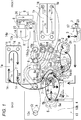
- the engine in an engine with an oil cooler 1 and an oil filter 2, as illustrated in Fig. 1 , the engine includes an oil gallery (3), a base attaching seat (5) provided in an engine frame wall (4), and a base for component mounting (6) attached to the base attaching seat (5), wherein the oil cooler (1) and the oil filter (2) are mounted on the base for component mounting (6), and the base attaching seat (5) is provided with an oil inlet (5a) communicating with an upstream-side passage (3a) of the oil gallery (3), and an oil outlet (5b) communicating with a downstream-side passage (3b) of the oil gallery (3), and as illustrated in Fig.
- the claimed invention exerts the following effects.
- a reason for this is that by mounting the oil cooler 1 and the oil filter 2 on the base for component mounting 6 beforehand in a subline of engine manufacturing, it suffices to only attach the base for component mounting 6 to the base attaching seat 5 in a main line.
- Figs. 1 to 9 are views for describing an engine according to an embodiment of the present invention, and in this embodiment, a vertical water-cooled multi-cylinder diesel engine will be described.
- an installation direction of a crank shaft 10 is defined as a front-back direction, and one thereof is front, and the other is back, and as shown in Fig. 8 , when viewed in a direction parallel to the installation direction of the crank shaft 10, a horizontal direction perpendicular to the front-back direction is defined as a right-left lateral direction, and a left-hand side when viewed from back to front is left, and a right-hand side is right.
- this engine includes a cylinder block 13 in which a cylinder portion 12 is integrally formed above a crank case 11, a cylinder head 14 assembled above the cylinder block 13, a cylinder head cover 15 assembled above the cylinder head 14, a water pump 16 and an oil pump 17 assembled in front of the cylinder block 13, an engine cooling fan 18 disposed in front of the water pump 16, a flywheel housing 19 disposed in back of the cylinder block 13, a flywheel 20 disposed inside the flywheel housing 19, and an oil pan 21 assembled under the cylinder block 13.
- a DPF case 22 containing a DPF is disposed just behind the cylinder head 14, and an SCR case 23 containing an SCR catalyst is disposed just above a back portion of the cylinder head cover 15, and a common rail 24 is disposed on the right side of the cylinder head 14.
- the DPF is an abbreviation of a diesel engine particulate filter, and catches PM in exhaust.
- the PM is an abbreviation of particulate matter.
- the SCR is an abbreviation of selected catalytic reduction.
- this engine includes an oil cooler 1, an oil filter 2, an oil gallery 3, a base attaching seat 5 provided in an engine frame wall 4, and a base for component mounting 6 attached to the base attaching seat 5, wherein the oil cooler 1 and the oil filter 2 are mounted on the base for component mounting 6, the base attaching seat 5 is provided with an oil inlet 5a communicating with an upstream-side passage 3a of the oil gallery 3, and an oil outlet 5b communicating with a downstream-side passage 3b of the oil gallery 3.
- a configuration is such that by attaching the base for component mounting 6 to the base attaching seat 5, engine oil 7 flowing into the oil inlet 5a of the base attaching seat 5 from the upstream-side passage 3a of the oil gallery 3 passes the base for component mounting 6, the oil cooler 1, and the oil filter 2, and flows out of the oil outlet 5b of the base attaching seat 5 to the downstream-side passage 3b of the oil gallery 3.
- the component mounting work becomes easy.
- a reason for this is that by mounting the oil cooler 1 and the oil filter 2 on the base for component mounting 6 beforehand in a subline of engine manufacturing, it suffices to only attach the base for component mounting 6 to the base attaching seat 5 in a main line.
- the base attaching seat 5 is configured so that the oil filter 2 can be attached thereto in place of the base for component mounting 6, and when the oil filter 2 is attached to the base attaching seat 5, the engine oil 7 flowing into the oil inlet 5a of the base attaching seat 5 from the upstream-side passage 3a of the oil gallery 3 passes the oil filter 2, and flows out of the oil outlet 5b of the base attaching seat 5 to the downstream-side passage 3b of the oil gallery 3.
- the base attaching seat 5 can be used as an oil filter attaching seat, and diversion of the cylinder block 13 to a model without the oil cooler 1 becomes easy.
- the oil cooler 1 and the oil filter 2 are disposed above and below, and as shown in Fig. 1 , the oil filter 2 on a lower side is located at a lower position than the oil inlet 5a and the oil outlet 5b of the base attaching seat 5.
- the oil gallery 3 is filled with the engine oil 7 in a short time, and the engine oil 7 is early supplied to a sliding portion 25 of the engine such as a bearing of the crank shaft 10 and the like, which can prevent burning of the sliding portion 25 due to lack of lubrication.
- the oil cooler 1 is formed longitudinally, and includes oil passages 1a, cooling water passages 1b in contact with the oil passages 1a, an oil passage inlet 1c and an oil passage outlet 1d each communicating with each of the oil passages 1a on one end side in a longitudinal direction, and a cooling water passage inlet 1e and a cooling water passage outlet 1f each communicating with each of the cooling water passages 1b on another end side in the longitudinal direction, and is configured such that the engine oil 7 flowing in from the oil passage inlet 1c on the one end side in the longitudinal direction is inverted at an oil passage inversion portion 1g on the other end portion in the longitudinal direction, and flows out of the oil passage outlet 1d on the one end side in the longitudinal direction, while cooling water 8 flowing in from the cooling water passage inlet 1e on the other end side in the longitudinal direction is inverted at a cooling water passage inversion portion 1h on the one end side in the longitudinal direction, and flows out of the cooling water passage outlet 1
- the base for component mounting 6 includes an oil filter attaching seat 6a, an upstream-side oil passage 6b on an upstream side of an oil flow channel with respect to the oil filter attaching seat 6a, and a downstream-side oil passage 6c on a downstream side of the oil flow channel with respect to the oil filter attaching seat 6a, wherein the upstream-side oil passage 6b is formed of a casted hole with a casting surface remaining in an inner circumferential surface thereof, and the downstream-side oil passage 6c is formed of a drilled hole.
- a cooling device of this engine includes a water jacket made up of a cylinder jacket 13a inside the cylinder block 13 and a head jacket 14a inside the cylinder head 14, the water pump 16 configured to pressure-feed the cooling water 8 to the cylinder jacket 13a, a thermostat housing 27 configured to lead out the cooling water 8 flowing into the head jacket 14a from the cylinder jacket 13a, a radiator 26 configured to introduce the cooling water 8 from the thermostat housing 27, and an engine cooling fan 18 configured to introduce engine cooling air 9 to the radiator 26.
- a lubricating device of this engine includes the oil pump 17 disposed in front of the cylinder block 13, the oil gallery 3 internally provided in a cylinder block wall 13b of the cylinder block 13, the base attaching seat 5 provided in an outer surface of the cylinder block wall 13b of the cylinder block 13, the base for component mounting 6 attached to the base attaching seat 5, and the oil cooler 1 and the oil filter 2 mounted on the base for component mounting base 6.
- the base for component mounting 6 includes a seating portion 6d configured to seat the base attaching seat 5 of the cylinder block 13 thereon, an oil cooler attaching seat 6e configured to attach the oil cooler 1 thereto, an oil filter attaching seat 6a configured to attach the oil filter 2 thereto, an upstream-side oil passage 6b, a downstream-side oil passage 6c, an upstream-side cooling water passage 6f, and a downstream-side cooling water passage 6g.
- the oil cooler 1 includes the plurality of oil passages 1a and the plurality of cooling water passages 1b, which are each layered alternately, an oil inlet pipe 1m provided with the oil passage inlets 1c of the oil passages 1a, an oil outlet pipe 1n provided with the oil passage outlets 1d of the oil passages 1a, a cooling water inlet pipe 1p provided with cooling water passage inlets 1e of the cooling water passages 1b, and a cooling water outlet pipe 1q provided with the cooling water passage outlets 1f of the cooling water passages 1b.
- the oil inlet pipe 1m and the oil outlet pipe 1n are disposed vertically on the one end side in the longitudinal direction (a back end side) of the oil passages 1a, and an oil passage partition wall 1r is led out of an inner wall surface on the one end side (the back side) of each of the oil passages 1a to the other end side (a front end side), so that this oil passage partition wall 1r vertically partitions the oil passage 1a, and the oil passage inversion portion 1g is formed on the other end side (the front end side) of the oil passage 1a.
- the engine oil 7 flowing into an upper one end side (an upper back end side) of the oil passage 1a from the oil passage inlet 1c of the oil inlet pipe 1m advances to the other end side (the front end side) inside an upper partition passage, is inverted to the one end side (the back end side) at the oil passage inversion portion 1g, advances to the one end side (the back end side) inside a lower partition passage, and flows out of the oil passage outlet 1d of the oil outlet pipe 1n on a lower one end side (a lower back end side) of the oil passage 1a.
- the cooling water outlet pipe 1q and the cooling water inlet pipe 1p are disposed vertically on the other end side in the longitudinal direction (the front side) of the cooling water passages 1b, and a cooling water passage partition wall 1s is led out of an inner wall surface on the other end side (the front side) of each of the cooling water passages 1b to the one end side (the back side), so that this cooling water passage partition wall 1s vertically partitions the cooling water passage 1b, and the cooling water passage inversion portion 1h is formed on the one end side (the back side) of the cooling water passage 1b.
- the cooling water 8 flowing into a lower other end side (a lower front end side) of the cooling water passage 1b from the cooling water passage inlet 1e of the cooling water inlet pipe 1p advances to the one end side (the back end side) inside a lower partition passage, is inverted to the other end side (the front end side) at the cooling water passage inversion portion 1h, advances to the other end side (the front end side) inside an upper partition passage, and flows out of the cooling water passage outlet 1f of the cooling water outlet pipe 1q on an upper other end side (an upper front end side) of the cooling water passage 1b.
- the oil filter 2 includes a cylindrical cup-shaped casing 2a, a cylindrical filter element 2b disposed concentrically inside the casing 2a, an unpurified oil chamber 2c closer to an outer circumference of the casing 2a partitioned by the filter element 2b, and a purified oil chamber 2d on a central side of the casing 2a.
- the seating portion 6d of the base for component mounting 6 includes an oil inlet chamber 6h closer to an outer circumference, the oil inlet chamber 6h being connected to the oil inlet 5a of the base attaching seat 5, and a base final oil outlet 6m on a central side, the base final oil outlet 6m being connected to the oil outlet 5b of the base attaching seat 5.
- the oil cooler attaching seat 6e includes an oil outlet 6n of the oil inlet chamber 6h into which the oil inlet pipe 1m of the oil cooler 1 is inserted, a reentry oil inlet 6p into which the oil outlet pipe 1n of the oil cooler 1 is inserted, the upstream-side cooling water passage 6f connected to a cooling water discharge hose 13d on a cooling water outlet 13c side of the cylinder jacket 13a, the downstream-side cooling water passage 6g connected to a cooling water suction hose 16a on a wager pump 16 side, the cooling water outlet 6q of the upstream-side cooling water passage 6f into which the cooling water inlet pipe 1p of the oil cooler 1 is inserted, and a cooling water inlet 6r of the downstream-side cooling water passage 6g into which the cooling water outlet pipe 1q of the oil cooler 1 is inserted.
- the oil filter attaching seat 6a includes an oil inlet chamber 6s closer to an outer circumference, and an oil outlet 6t in a central portion, wherein the reentry oil inlet 6p of the oil cooler attaching seat 6e and the oil inlet chamber 6s of the oil filter attaching seat 6a are communicated by the upstream-side oil passage 6b, and the oil inlet chamber 6s is communicated with the unpurified oil chamber 2c of the oil filter 2, the purified oil chamber 2d of the oil filter 2 and the oil outlet 6t of the oil filter attaching seat 6a are communicated, and this oil outlet 6t and the base final oil outlet 6m of the seating portion 6d are communicated by the downstream-side oil passage 6c.
- the engine oil 7 inside the oil pan 21 sequentially passes through the oil pump 17, the upstream-side passage 3a of the oil gallery 3, the oil inlet 5a of the base attaching seat 5, the oil inlet chamber 6h of the seating portion 6d of the base for component mounting 6, the oil outlet 6n, the oil inlet pipe 1m of the oil cooler 1, the oil passage 1a, the oil outlet pipe 1n, the reentry oil inlet 6p of the oil cooler attaching seat 6e, the upstream-side oil passage 6b, the oil inlet chamber 6s of the oil filter attaching seat 6a, the unpurified oil chamber 2c of the oil filter 2, the filter element 2b, the purified oil chamber 2d, the oil outlet 6t of the oil filter attaching seat 6a, the downstream-side oil passage 6c, the base final oil outlet 6m, the oil outlet 5b of the base attaching seat 5, the downstream-side passage 3b of the oil gallery 3, and the sliding portion 25 such as the bearing of the crank shaft 10 and the like to return to the oil
- the cooling water 8 inside the cylinder jacket 13a sequentially passes through the head jacket 14a, the thermostat housing 27, the radiator 26, and the water pump 16 to return to the cylinder jacket 13a, while part of the cooling water 8 sequentially passes through the cooling water outlet 13c of the cylinder jacket 13a, the cooling water discharge hose 13d, the upstream-side cooling water passage 6f of the oil cooler attaching seat 6e, the cooling water inlet pipe 1p of the oil cooler 1, the cooling water passage 1b, the cooling water outlet pipe 1q, the cooling water inlet 6r, the downstream-side cooling water passage 6g, the cooling water suction hose 16a, and the water pump 16 to return to the cylinder jacket 13a.
Landscapes
- Engineering & Computer Science (AREA)
- Mechanical Engineering (AREA)
- General Engineering & Computer Science (AREA)
- Chemical & Material Sciences (AREA)
- Chemical Kinetics & Catalysis (AREA)
- Combustion & Propulsion (AREA)
- Lubrication Of Internal Combustion Engines (AREA)
- Lubrication Details And Ventilation Of Internal Combustion Engines (AREA)
Abstract
Description
- The present invention relates to an engine, and particularly to an engine that does not require additional processing at the time of component mounting, and component mounting work of which is also easy.
- Conventionally, there has been an engine including an oil cooler and an oil filter (e.g., refer to Japanese Patent Application Laid-open No.
2011-58480 Figs. 4A to 4C )). - According to this type of engine, there is an advantage that cooling and purification of engine oil can be performed.
- Problems of the invention of Japanese Patent Application Laid-open No.
2011-58480 - «
Problem 1» Additional processing for a drilled hole at the time of component mounting is required. - When the oil cooler is mounted on an engine, the additional processing for the drilled hole opening a communication passage configured to communicate the oil cooler and the oil filter in a crank case is required.
- «
Problem 2» Component mounting in an engine manufacturing line is complicated. - Since the oil cooler and the oil filter need to be mounted individually on the engine, the component mounting work in the engine manufacturing line is complicated.
- An object of the present invention is to provide an engine that does not require additional processing at the time of component mounting, and component mounting work of which is also easy.
- The matters used to specify the invention according to
claim 1 are as follows. - As illustrated in
Fig. 1 , in an engine with anoil cooler 1 and anoil filter 2,
as illustrated inFig. 1 , the engine includes an oil gallery (3), a base attaching seat (5) provided in an engine frame wall (4), and a base for component mounting (6) attached to the base attaching seat (5), wherein the oil cooler (1) and the oil filter (2) are mounted on the base for component mounting (6), and the base attaching seat (5) is provided with an oil inlet (5a) communicating with an upstream-side passage (3a) of the oil gallery (3), and an oil outlet (5b) communicating with a downstream-side passage (3b) of the oil gallery (3), and
as illustrated inFig. 1 , by attaching the base for component mounting (6) to the base attaching seat (5), engine oil (7) flowing into the oil inlet (5a) of the base attaching seat (5) from the upstream-side passage (3a) of the oil gallery (3) passes the base for component mounting (6), the oil cooler (1), and the oil filter (2), and flows out of the oil outlet (5b) of the base attaching seat (5) to the downstream-side passage (3b) of the oil gallery (3). - The claimed invention exerts the following effects.
- A reason for this is that as illustrated in
Fig. 1 , only attaching the base for component mounting 6 to thebase attaching seat 5 allows theengine oil 7 to pass theoil cooler 1 and theoil filter 2. - A reason for this is that by mounting the
oil cooler 1 and theoil filter 2 on the base for component mounting 6 beforehand in a subline of engine manufacturing, it suffices to only attach the base for component mounting 6 to thebase attaching seat 5 in a main line. -
-
Fig. 1 is a schematic view of a substantial portion of an engine according to an embodiment of the present invention; -
Fig. 2 is a side view of a cylinder block of the engine inFig. 1 ; -
Figs. 3A to 3C are views for describing a base for component mounting used in the engine inFig. 1 ,Fig. 3A being a front view,Fig. 3B being a back view, andFig. 3C being a cross-sectional view along C-C line inFig. 3A ; -
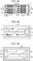
Figs. 4A to 4C are views for describing an oil cooler used in the engine inFig. 1 ,Fig. 4A being a longitudinal section bottom view,Fig. 4B being a cross-sectional view along B-B line inFig. 4A, and Fig. 4C is a cross-sectional view along C-C line inFig. 4A ; -
Fig. 5 is a right side view of the engine inFig. 1 ; -
Fig. 6 is a front view of the engine inFig. 1 ; -
Fig. 7 is a left side view of the engine inFig. 1 ; -
Fig. 8 is a back view of the engine inFig. 1 ; and -
Fig. 9 is a plan view of the engine inFig. 1 . -
Figs. 1 to 9 are views for describing an engine according to an embodiment of the present invention, and in this embodiment, a vertical water-cooled multi-cylinder diesel engine will be described. - An outline of this engine is as follows.
- As shown in
Fig. 5 , an installation direction of acrank shaft 10 is defined as a front-back direction, and one thereof is front, and the other is back, and as shown inFig. 8 , when viewed in a direction parallel to the installation direction of thecrank shaft 10, a horizontal direction perpendicular to the front-back direction is defined as a right-left lateral direction, and a left-hand side when viewed from back to front is left, and a right-hand side is right. - As shown in
Figs. 5 to 9 , this engine includes acylinder block 13 in which acylinder portion 12 is integrally formed above acrank case 11, acylinder head 14 assembled above thecylinder block 13, acylinder head cover 15 assembled above thecylinder head 14, awater pump 16 and anoil pump 17 assembled in front of thecylinder block 13, anengine cooling fan 18 disposed in front of thewater pump 16, aflywheel housing 19 disposed in back of thecylinder block 13, aflywheel 20 disposed inside theflywheel housing 19, and anoil pan 21 assembled under thecylinder block 13. - As shown in
Fig. 5 , aDPF case 22 containing a DPF is disposed just behind thecylinder head 14, and anSCR case 23 containing an SCR catalyst is disposed just above a back portion of thecylinder head cover 15, and acommon rail 24 is disposed on the right side of thecylinder head 14. The DPF is an abbreviation of a diesel engine particulate filter, and catches PM in exhaust. The PM is an abbreviation of particulate matter. The SCR is an abbreviation of selected catalytic reduction. - As shown in
Fig. 1 , this engine includes anoil cooler 1, anoil filter 2, an oil gallery 3, abase attaching seat 5 provided in anengine frame wall 4, and a base forcomponent mounting 6 attached to thebase attaching seat 5, wherein theoil cooler 1 and theoil filter 2 are mounted on the base forcomponent mounting 6, thebase attaching seat 5 is provided with anoil inlet 5a communicating with an upstream-side passage 3a of the oil gallery 3, and anoil outlet 5b communicating with a downstream-side passage 3b of the oil gallery 3. - As shown in
Fig. 1 , a configuration is such that by attaching the base forcomponent mounting 6 to thebase attaching seat 5,engine oil 7 flowing into theoil inlet 5a of thebase attaching seat 5 from the upstream-side passage 3a of the oil gallery 3 passes the base forcomponent mounting 6, theoil cooler 1, and theoil filter 2, and flows out of theoil outlet 5b of thebase attaching seat 5 to the downstream-side passage 3b of the oil gallery 3. - The above-described configuration makes unnecessary additional processing of a drilled hole at the time of component mounting. A reason for this is that as shown in
Fig. 1 , only attaching the base for component mounting 6 to thebase attaching seat 5 allows theengine oil 7 to pass theoil cooler 1 and theoil filter 2. - Moreover, the component mounting work becomes easy. A reason for this is that by mounting the
oil cooler 1 and theoil filter 2 on the base for component mounting 6 beforehand in a subline of engine manufacturing, it suffices to only attach the base for component mounting 6 to thebase attaching seat 5 in a main line. - The
base attaching seat 5 is configured so that theoil filter 2 can be attached thereto in place of the base forcomponent mounting 6, and when theoil filter 2 is attached to thebase attaching seat 5, theengine oil 7 flowing into theoil inlet 5a of thebase attaching seat 5 from the upstream-side passage 3a of the oil gallery 3 passes theoil filter 2, and flows out of theoil outlet 5b of thebase attaching seat 5 to the downstream-side passage 3b of the oil gallery 3. - Therefore, if the
oil cooler 1 is unnecessary, thebase attaching seat 5 can be used as an oil filter attaching seat, and diversion of thecylinder block 13 to a model without theoil cooler 1 becomes easy. - As shown in
Figs. 1 and5 , theoil cooler 1 and theoil filter 2 are disposed above and below, and as shown inFig. 1 , theoil filter 2 on a lower side is located at a lower position than theoil inlet 5a and theoil outlet 5b of thebase attaching seat 5. Thus, even if theengine oil 7 inside the oil gallery 3 flows down to the oil pan after the engine stops, theengine oil 7 inside theoil filter 2 is retained, and at the next engine start time, the oil gallery 3 is filled with theengine oil 7 in a short time, and theengine oil 7 is early supplied to a sliding portion 25 of the engine such as a bearing of thecrank shaft 10 and the like, which can prevent burning of the sliding portion 25 due to lack of lubrication. - As shown in
Fig. 1 andFigs. 4A to 4C , theoil cooler 1 is formed longitudinally, and includesoil passages 1a,cooling water passages 1b in contact with theoil passages 1a, an oil passage inlet 1c and anoil passage outlet 1d each communicating with each of theoil passages 1a on one end side in a longitudinal direction, and a cooling water passage inlet 1e and a coolingwater passage outlet 1f each communicating with each of thecooling water passages 1b on another end side in the longitudinal direction, and is configured such that theengine oil 7 flowing in from the oil passage inlet 1c on the one end side in the longitudinal direction is inverted at an oilpassage inversion portion 1g on the other end portion in the longitudinal direction, and flows out of theoil passage outlet 1d on the one end side in the longitudinal direction, while coolingwater 8 flowing in from the cooling water passage inlet 1e on the other end side in the longitudinal direction is inverted at a cooling waterpassage inversion portion 1h on the one end side in the longitudinal direction, and flows out of the coolingwater passage outlet 1f on the other end side in the longitudinal direction. - This makes long a passage route of the
engine oil 7 and thecooling water 8 inside theoil cooler 1, and promotes heat exchange between theengine oil 7 and thecooling water 8, so that cooling efficiency of theengine oil 7 becomes high. - As shown in
Fig. 1 andFigs. 3A, 3B and 3C , the base for component mounting 6 includes an oilfilter attaching seat 6a, an upstream-side oil passage 6b on an upstream side of an oil flow channel with respect to the oilfilter attaching seat 6a, and a downstream-side oil passage 6c on a downstream side of the oil flow channel with respect to the oilfilter attaching seat 6a, wherein the upstream-side oil passage 6b is formed of a casted hole with a casting surface remaining in an inner circumferential surface thereof, and the downstream-side oil passage 6c is formed of a drilled hole. - This can reduce a manufacturing cost of the base for component mounting 6 because the upstream-
side oil passage 6b can be formed of the casted hole, and further, even if casting sand remaining in the inner circumferential surface of the upstream-side oil passage 6b comes off, this casting sand is caught in theoil filter 2, and does not flow out to the downstream side of the oil flow channel, so that a flaw due to coming-off of the casting sand can be prevented. - As shown in
Fig. 1 , a cooling device of this engine includes a water jacket made up of acylinder jacket 13a inside thecylinder block 13 and ahead jacket 14a inside thecylinder head 14, thewater pump 16 configured to pressure-feed the coolingwater 8 to thecylinder jacket 13a, athermostat housing 27 configured to lead out the coolingwater 8 flowing into thehead jacket 14a from thecylinder jacket 13a, aradiator 26 configured to introduce thecooling water 8 from thethermostat housing 27, and anengine cooling fan 18 configured to introduceengine cooling air 9 to theradiator 26. - As shown in
Figs. 1 and2 , a lubricating device of this engine includes theoil pump 17 disposed in front of thecylinder block 13, the oil gallery 3 internally provided in acylinder block wall 13b of thecylinder block 13, thebase attaching seat 5 provided in an outer surface of thecylinder block wall 13b of thecylinder block 13, the base for component mounting 6 attached to thebase attaching seat 5, and theoil cooler 1 and theoil filter 2 mounted on the base forcomponent mounting base 6. - As shown in
Fig. 1 andFigs. 3A to 3C , the base for component mounting 6 includes aseating portion 6d configured to seat thebase attaching seat 5 of thecylinder block 13 thereon, an oilcooler attaching seat 6e configured to attach theoil cooler 1 thereto, an oilfilter attaching seat 6a configured to attach theoil filter 2 thereto, an upstream-side oil passage 6b, a downstream-side oil passage 6c, an upstream-sidecooling water passage 6f, and a downstream-sidecooling water passage 6g. - As shown in
Fig. 1 andFigs. 4A to 4C , theoil cooler 1 includes the plurality ofoil passages 1a and the plurality of coolingwater passages 1b, which are each layered alternately, anoil inlet pipe 1m provided with theoil passage inlets 1c of theoil passages 1a, anoil outlet pipe 1n provided with theoil passage outlets 1d of theoil passages 1a, a coolingwater inlet pipe 1p provided with coolingwater passage inlets 1e of the coolingwater passages 1b, and a coolingwater outlet pipe 1q provided with the coolingwater passage outlets 1f of the coolingwater passages 1b. - As shown in
Fig. 1 andFigs. 4A to 4C , theoil inlet pipe 1m and theoil outlet pipe 1n are disposed vertically on the one end side in the longitudinal direction (a back end side) of theoil passages 1a, and an oilpassage partition wall 1r is led out of an inner wall surface on the one end side (the back side) of each of theoil passages 1a to the other end side (a front end side), so that this oilpassage partition wall 1r vertically partitions theoil passage 1a, and the oilpassage inversion portion 1g is formed on the other end side (the front end side) of theoil passage 1a. - In this
oil cooler 1, theengine oil 7 flowing into an upper one end side (an upper back end side) of theoil passage 1a from theoil passage inlet 1c of theoil inlet pipe 1m advances to the other end side (the front end side) inside an upper partition passage, is inverted to the one end side (the back end side) at the oilpassage inversion portion 1g, advances to the one end side (the back end side) inside a lower partition passage, and flows out of theoil passage outlet 1d of theoil outlet pipe 1n on a lower one end side (a lower back end side) of theoil passage 1a. - As shown in
Fig. 1 andFigs. 4A to 4C , the coolingwater outlet pipe 1q and the coolingwater inlet pipe 1p are disposed vertically on the other end side in the longitudinal direction (the front side) of the coolingwater passages 1b, and a cooling waterpassage partition wall 1s is led out of an inner wall surface on the other end side (the front side) of each of the coolingwater passages 1b to the one end side (the back side), so that this cooling waterpassage partition wall 1s vertically partitions the coolingwater passage 1b, and the cooling waterpassage inversion portion 1h is formed on the one end side (the back side) of the coolingwater passage 1b. - In this
oil cooler 1, the coolingwater 8 flowing into a lower other end side (a lower front end side) of the coolingwater passage 1b from the coolingwater passage inlet 1e of the coolingwater inlet pipe 1p advances to the one end side (the back end side) inside a lower partition passage, is inverted to the other end side (the front end side) at the cooling waterpassage inversion portion 1h, advances to the other end side (the front end side) inside an upper partition passage, and flows out of the coolingwater passage outlet 1f of the coolingwater outlet pipe 1q on an upper other end side (an upper front end side) of the coolingwater passage 1b. - As shown in
Fig. 1 , theoil filter 2 includes a cylindrical cup-shapedcasing 2a, acylindrical filter element 2b disposed concentrically inside thecasing 2a, anunpurified oil chamber 2c closer to an outer circumference of thecasing 2a partitioned by thefilter element 2b, and a purifiedoil chamber 2d on a central side of thecasing 2a. - As shown in
Fig. 1 andFigs. 3A to 3C , theseating portion 6d of the base for component mounting 6 includes anoil inlet chamber 6h closer to an outer circumference, theoil inlet chamber 6h being connected to theoil inlet 5a of thebase attaching seat 5, and a basefinal oil outlet 6m on a central side, the basefinal oil outlet 6m being connected to theoil outlet 5b of thebase attaching seat 5. - As shown in
Fig. 1 andFigs. 3A to 3C , the oilcooler attaching seat 6e includes anoil outlet 6n of theoil inlet chamber 6h into which theoil inlet pipe 1m of theoil cooler 1 is inserted, areentry oil inlet 6p into which theoil outlet pipe 1n of theoil cooler 1 is inserted, the upstream-sidecooling water passage 6f connected to a coolingwater discharge hose 13d on a coolingwater outlet 13c side of thecylinder jacket 13a, the downstream-sidecooling water passage 6g connected to a coolingwater suction hose 16a on awager pump 16 side, the cooling water outlet 6q of the upstream-sidecooling water passage 6f into which the coolingwater inlet pipe 1p of theoil cooler 1 is inserted, and a coolingwater inlet 6r of the downstream-sidecooling water passage 6g into which the coolingwater outlet pipe 1q of theoil cooler 1 is inserted. - As shown in
Fig. 1 andFigs. 3A to 3C , the oilfilter attaching seat 6a includes anoil inlet chamber 6s closer to an outer circumference, and anoil outlet 6t in a central portion, wherein thereentry oil inlet 6p of the oilcooler attaching seat 6e and theoil inlet chamber 6s of the oilfilter attaching seat 6a are communicated by the upstream-side oil passage 6b, and theoil inlet chamber 6s is communicated with theunpurified oil chamber 2c of theoil filter 2, the purifiedoil chamber 2d of theoil filter 2 and theoil outlet 6t of the oilfilter attaching seat 6a are communicated, and thisoil outlet 6t and the basefinal oil outlet 6m of theseating portion 6d are communicated by the downstream-side oil passage 6c. - As shown in
Fig. 1 , theengine oil 7 inside theoil pan 21 sequentially passes through theoil pump 17, the upstream-side passage 3a of the oil gallery 3, theoil inlet 5a of thebase attaching seat 5, theoil inlet chamber 6h of theseating portion 6d of the base for component mounting 6, theoil outlet 6n, theoil inlet pipe 1m of theoil cooler 1, theoil passage 1a, theoil outlet pipe 1n, thereentry oil inlet 6p of the oilcooler attaching seat 6e, the upstream-side oil passage 6b, theoil inlet chamber 6s of the oilfilter attaching seat 6a, theunpurified oil chamber 2c of theoil filter 2, thefilter element 2b, the purifiedoil chamber 2d, theoil outlet 6t of the oilfilter attaching seat 6a, the downstream-side oil passage 6c, the basefinal oil outlet 6m, theoil outlet 5b of thebase attaching seat 5, the downstream-side passage 3b of the oil gallery 3, and the sliding portion 25 such as the bearing of thecrank shaft 10 and the like to return to theoil pan 21. - As shown in
Fig. 1 , the coolingwater 8 inside thecylinder jacket 13a sequentially passes through thehead jacket 14a, thethermostat housing 27, theradiator 26, and thewater pump 16 to return to thecylinder jacket 13a, while part of the coolingwater 8 sequentially passes through the coolingwater outlet 13c of thecylinder jacket 13a, the coolingwater discharge hose 13d, the upstream-sidecooling water passage 6f of the oilcooler attaching seat 6e, the coolingwater inlet pipe 1p of theoil cooler 1, the coolingwater passage 1b, the coolingwater outlet pipe 1q, the coolingwater inlet 6r, the downstream-sidecooling water passage 6g, the coolingwater suction hose 16a, and thewater pump 16 to return to thecylinder jacket 13a.
Claims (5)
- An engine with an oil cooler 1 and an oil filter 2 comprising:an oil gallery 3;a base attaching seat 5 provided in an engine frame wall 4; anda base for component mounting 6 attached to the base attaching seat 5;wherein the oil cooler 1 and the oil filter 2 are mounted on the base for component mounting 6, and the base attaching seat 5 is provided with an oil inlet 5a communicating with an upstream-side passage 3a of the oil gallery 3, and an oil outlet 5b communicating with a downstream-side passage 3b of the oil gallery 3, andby attaching the base for component mounting 6 to the base attaching seat 5, engine oil 7 flowing into the oil inlet 5a of the base attaching seat 5 from the upstream-side passage 3a of the oil gallery 3 passes the base for component mounting 6, the oil cooler 1, and the oil filter 2, and flows out of the oil outlet 5b of the base attaching seat 5 to the downstream-side passage 3b of the oil gallery 3.
- The engine according to claim 1, wherein the base attaching seat 5 is configured so that the oil filter 2 can be attached thereto in place of the base for component mounting 6, and when the oil filter 2 is attached to the base attaching seat 5, the engine oil 7 flowing into the oil inlet 5a of the base attaching seat 5 from the upstream-side passage 3a of the oil gallery 3 passes the oil filter 2, and flows out of the oil outlet 5b of the base attaching seat 5 to the downstream-side passage 3b of the oil gallery 3.
- The engine according to claim 1 or claim 2, wherein the oil cooler 1 and the oil filter 2 are disposed above and below, and the lower component 2 of these components 1 and 2 is located at a lower position than the oil inlet 5a and the oil outlet 5b of the base attaching seat 5.
- The engine according to any one of claims 1 to 3, wherein the oil cooler 1 is formed longitudinally, and includes oil passages 1a, cooling water passages 1b in contact with the oil passages 1a, an oil passage inlet 1c and an oil passage outlet 1d each communicating with each of the oil passages 1a on one end side in a longitudinal direction, and a cooling water passage inlet 1e and a cooling water passage outlet 1f each communicating with each of the cooling water passages 1b on another end side in the longitudinal direction, and the engine oil 7 flowing in from the oil passage inlet 1c on the one end side in the longitudinal direction is inverted at an oil passage inversion portion 1g on the other end side in the longitudinal direction, and flows out of the oil passage outlet 1d on the one end side in the longitudinal direction, while cooling water 8 flowing in from the cooling water passage inlet 1e on the other end side in the longitudinal direction is inverted at a cooling water passage inversion portion 1h on the one end side in the longitudinal direction, and flows out of the cooling water passage outlet 1f on the other end side in the longitudinal direction.
- The engine according to any one of claims 1 to 4, wherein the base for component mounting 6 includes an oil filter attaching seat 6a, an upstream-side oil passage 6b on an upstream side of an oil flow channel with respect to the oil filter attaching seat 6a, and a downstream-side oil passage 6c on a downstream side of the oil flow channel with respect to the oil filter attaching seat 6a, and the upstream-side oil passage 6b is formed of a casted hole with a casting surface remaining in an inner circumferential surface thereof, and the downstream-side oil passage 6c is formed of a drilled hole.
Applications Claiming Priority (1)
| Application Number | Priority Date | Filing Date | Title |
|---|---|---|---|
| JP2016254811A JP6646569B2 (en) | 2016-12-28 | 2016-12-28 | engine |
Publications (2)
| Publication Number | Publication Date |
|---|---|
| EP3342993A1 true EP3342993A1 (en) | 2018-07-04 |
| EP3342993B1 EP3342993B1 (en) | 2023-12-27 |
Family
ID=60409177
Family Applications (1)
| Application Number | Title | Priority Date | Filing Date |
|---|---|---|---|
| EP17202355.8A Active EP3342993B1 (en) | 2016-12-28 | 2017-11-17 | Engine |
Country Status (4)
| Country | Link |
|---|---|
| US (1) | US10837328B2 (en) |
| EP (1) | EP3342993B1 (en) |
| JP (1) | JP6646569B2 (en) |
| CN (1) | CN108252764B (en) |
Families Citing this family (2)
| Publication number | Priority date | Publication date | Assignee | Title |
|---|---|---|---|---|
| JP7680987B2 (en) * | 2022-06-30 | 2025-05-21 | 株式会社クボタ | engine |
| JP7490713B2 (en) | 2022-06-30 | 2024-05-27 | 株式会社クボタ | Water-cooled engine |
Citations (6)
| Publication number | Priority date | Publication date | Assignee | Title |
|---|---|---|---|---|
| US3830289A (en) * | 1972-05-18 | 1974-08-20 | D Olson | Oil cooler |
| EP0750099A2 (en) * | 1995-06-23 | 1996-12-27 | Isuzu Motors Limited | Thermostat housing for internal combustion engine |
| FR2871516A1 (en) * | 2004-06-15 | 2005-12-16 | Renault Sas | COOLING SYSTEM FOR MOTOR VEHICLE WITH WATER CIRCUIT AND OIL CIRCUIT |
| DE102005011221A1 (en) * | 2005-03-11 | 2006-09-14 | Mann+Hummel Gmbh | Liquid filter-heat exchanger unit |
| DE102005012550A1 (en) * | 2005-03-18 | 2006-09-21 | Mahle International Gmbh | Filter-cooler combination for liquids, in particular lubricating oil of a motor vehicle internal combustion engine |
| JP2011058480A (en) | 2009-09-14 | 2011-03-24 | Kawasaki Heavy Ind Ltd | Crankcase, engine, and method of manufacturing crankcase |
Family Cites Families (50)
| Publication number | Priority date | Publication date | Assignee | Title |
|---|---|---|---|---|
| US3223197A (en) * | 1960-06-08 | 1965-12-14 | Gen Motors Corp | Oil pump and cooler assembly for an internal combustion engine |
| US3353590A (en) * | 1965-07-12 | 1967-11-21 | Holman And Moody Inc | Unitary oil filtering and cooling attachment for internal combustion engines |
| JPS55104511A (en) * | 1979-01-31 | 1980-08-11 | Nissan Motor Co Ltd | Fixing structure for oil filter and oil cooler |
| US4324213A (en) * | 1980-01-21 | 1982-04-13 | Cummins Engine Company, Inc. | Lubrication fluid filtering and cooling assembly |
| US4423708A (en) * | 1981-12-31 | 1984-01-03 | Cummins Engine Company, Inc. | Liquid cooling unit for an internal combustion engine |
| US4426965A (en) * | 1982-02-11 | 1984-01-24 | Cummins Engine Company, Inc. | Unitized oil cooler and filter assembly |
| JPS5996410A (en) * | 1982-11-24 | 1984-06-02 | Honda Motor Co Ltd | Device for lubricating oil passage in internal-combustion engine |
| DE3440064A1 (en) * | 1984-11-02 | 1986-05-07 | Süddeutsche Kühlerfabrik Julius Fr. Behr GmbH & Co KG, 7000 Stuttgart | OIL COOLER |
| DE3803546A1 (en) * | 1987-02-06 | 1988-08-18 | Honda Motor Co Ltd | COOLING SYSTEM FOR WATER COOLING MOTOR OIL OF A MOTOR VEHICLE |
| DE3827570A1 (en) * | 1988-08-13 | 1990-02-15 | Porsche Ag | DEVICE FOR CLEANING LUBRICANT OIL |
| US5006237A (en) * | 1989-08-14 | 1991-04-09 | Jones Floyd B | Spin-on oil filter adaptor for four cylinder continental aircraft engines |
| US5014775A (en) * | 1990-05-15 | 1991-05-14 | Toyo Radiator Co., Ltd. | Oil cooler and manufacturing method thereof |
| US5099912A (en) * | 1990-07-30 | 1992-03-31 | Calsonic Corporation | Housingless oil cooler |
| US5199395A (en) * | 1990-10-18 | 1993-04-06 | Honda Giken Kogyo Kabushiki Kaisha | Four-cycle engine |
| DE69321926T2 (en) * | 1992-12-21 | 1999-04-01 | Calsonic Corp., Tokio/Tokyo | Oil cooler without housing and process for its manufacture |
| US5351664A (en) * | 1993-04-16 | 1994-10-04 | Kohler Co. | Oil cooling device |
| US5647315A (en) * | 1994-10-07 | 1997-07-15 | Yamaha Hatsudoki Kabushiki Kaisha | Lubricating arrangement for engine |
| GB2294091B (en) * | 1994-10-14 | 1999-05-26 | Perkins Ltd | An assembly of auxiliary apparatus for an internal combustion engine |
| US5544699A (en) * | 1995-02-10 | 1996-08-13 | Modine Manufacturing Company | Oil cooler with a self-fastening, self-orienting pressure relief valve |
| US5887561A (en) * | 1996-07-02 | 1999-03-30 | Spurgin; Robert E | Oil cooler for a motorcycle |
| DE19626867A1 (en) * | 1996-07-04 | 1998-01-29 | Daimler Benz Ag | Carrier part that can be flanged onto a crankcase of an internal combustion engine for units for lubricating oil supply and treatment |
| US5771854A (en) * | 1997-01-07 | 1998-06-30 | Ray Barton Racing Engines, Inc. | Oil pump adaptor |
| JPH10196343A (en) * | 1997-01-17 | 1998-07-28 | Kubota Corp | Oil filter mounting device |
| JPH10212919A (en) * | 1997-01-31 | 1998-08-11 | Suzuki Motor Corp | Engine oil filter mounting structure |
| EP1001144B1 (en) * | 1998-11-13 | 2004-01-21 | Denso Corporation | Oil cooler mounting structure |
| JP4077610B2 (en) * | 2001-03-16 | 2008-04-16 | カルソニックカンセイ株式会社 | Housingless oil cooler |
| DE10152363A1 (en) * | 2001-10-24 | 2003-05-08 | Modine Mfg Co | Caseless plate heat exchanger |
| JP4354252B2 (en) * | 2002-10-29 | 2009-10-28 | 川崎重工業株式会社 | Oil cooler and small ship |
| JP4328652B2 (en) * | 2004-03-23 | 2009-09-09 | 株式会社クボタ | Engine lubricating oil cooling and filtration equipment |
| JP4494271B2 (en) * | 2005-03-31 | 2010-06-30 | 富士重工業株式会社 | Oil cooling device for air cooling engine |
| JP2007170361A (en) * | 2005-12-26 | 2007-07-05 | Mazda Motor Corp | Engine oil cooler mounting structure |
| US7621251B1 (en) * | 2006-03-10 | 2009-11-24 | Polaris Industries Inc. | Lubrication cooling system for a vehicle |
| DE102006031608A1 (en) * | 2006-07-06 | 2008-01-17 | Behr Gmbh & Co. Kg | Heat exchanger filter arrangement, in particular for a motor vehicle |
| US20090038580A1 (en) * | 2007-08-06 | 2009-02-12 | Irp,Llc | Oil cooler for motor vehicles |
| JP2009103360A (en) * | 2007-10-23 | 2009-05-14 | Tokyo Roki Co Ltd | Plate stack heat exchanger |
| WO2009054162A1 (en) * | 2007-10-23 | 2009-04-30 | Tokyo Roki Co. Ltd. | Plate-stacking type heat exchanger |
| DE102007052706A1 (en) * | 2007-11-06 | 2009-05-07 | Modine Manufacturing Co., Racine | heat exchangers |
| DE102008031684B4 (en) * | 2008-07-04 | 2020-02-06 | Mahle International Gmbh | cooling device |
| JP5629487B2 (en) * | 2010-04-13 | 2014-11-19 | 東京濾器株式会社 | oil cooler |
| DE102010021990A1 (en) * | 2010-05-29 | 2011-12-01 | Mahle International Gmbh | Filtering and cooling device |
| CN201738976U (en) * | 2010-06-30 | 2011-02-09 | 长城汽车股份有限公司 | Interface device of oil filter |
| US20120090811A1 (en) * | 2010-10-19 | 2012-04-19 | E & D Holdings, LLC | Oil cooler assembly |
| DE202011002197U1 (en) * | 2011-02-01 | 2012-02-02 | Dana Gmbh | heat exchangers |
| US8887688B1 (en) * | 2011-03-22 | 2014-11-18 | Gene Neal | Oil filtering and cooling system for compression ignition engines |
| CN202100295U (en) * | 2011-05-31 | 2012-01-04 | 长城汽车股份有限公司 | Integrated installing seat for oil filter and oil cooler of automobile engine |
| US8875667B2 (en) * | 2012-01-03 | 2014-11-04 | Ford Global Technologies, Llc | Oil cooler |
| CN103670584B (en) * | 2012-09-13 | 2016-08-03 | 北京汽车动力总成有限公司 | Lubricant of Automobile Engine filtering cooling integrated morphology and automobile |
| US10161500B2 (en) * | 2015-03-31 | 2018-12-25 | Amarillo Gear Company Llc | Oil pump plate for in-line filter system |
| KR101745200B1 (en) * | 2015-12-09 | 2017-06-09 | 현대자동차주식회사 | Supplying apparatus of engine oil |
| US10598124B2 (en) * | 2016-04-08 | 2020-03-24 | Yanmar Co., Ltd. | Engine device |
-
2016
- 2016-12-28 JP JP2016254811A patent/JP6646569B2/en active Active
-
2017
- 2017-11-17 EP EP17202355.8A patent/EP3342993B1/en active Active
- 2017-12-07 US US15/834,393 patent/US10837328B2/en active Active
- 2017-12-08 CN CN201711303184.9A patent/CN108252764B/en active Active
Patent Citations (6)
| Publication number | Priority date | Publication date | Assignee | Title |
|---|---|---|---|---|
| US3830289A (en) * | 1972-05-18 | 1974-08-20 | D Olson | Oil cooler |
| EP0750099A2 (en) * | 1995-06-23 | 1996-12-27 | Isuzu Motors Limited | Thermostat housing for internal combustion engine |
| FR2871516A1 (en) * | 2004-06-15 | 2005-12-16 | Renault Sas | COOLING SYSTEM FOR MOTOR VEHICLE WITH WATER CIRCUIT AND OIL CIRCUIT |
| DE102005011221A1 (en) * | 2005-03-11 | 2006-09-14 | Mann+Hummel Gmbh | Liquid filter-heat exchanger unit |
| DE102005012550A1 (en) * | 2005-03-18 | 2006-09-21 | Mahle International Gmbh | Filter-cooler combination for liquids, in particular lubricating oil of a motor vehicle internal combustion engine |
| JP2011058480A (en) | 2009-09-14 | 2011-03-24 | Kawasaki Heavy Ind Ltd | Crankcase, engine, and method of manufacturing crankcase |
Also Published As
| Publication number | Publication date |
|---|---|
| CN108252764B (en) | 2021-12-14 |
| JP6646569B2 (en) | 2020-02-14 |
| EP3342993B1 (en) | 2023-12-27 |
| US10837328B2 (en) | 2020-11-17 |
| JP2018105277A (en) | 2018-07-05 |
| CN108252764A (en) | 2018-07-06 |
| US20180179927A1 (en) | 2018-06-28 |
Similar Documents
| Publication | Publication Date | Title |
|---|---|---|
| JP6438917B2 (en) | Breather device for internal combustion engine | |
| JP4830000B2 (en) | Fluid passage structure of internal combustion engine | |
| US20090194061A1 (en) | Oil Module Comprising An Integrated Cooling Water Channel | |
| EP3342993B1 (en) | Engine | |
| US4497293A (en) | Internal combustion engine of motorcycle | |
| US8757111B2 (en) | Engine assembly including cooling system | |
| EP2052135B1 (en) | Crankcase for an internal combustion engine | |
| JP2013104299A (en) | Internal combustion engine | |
| JP2000045741A (en) | Cylinder head of internal combustion engine | |
| BR0002860A (en) | Improvements in pump housing for internal combustion engines | |
| JP2002256838A (en) | Engine breather structure | |
| RU2012126753A (en) | INTERNAL COMBUSTION ENGINE MODULE, MODULE HOUSING AND INTERNAL COMBUSTION ENGINE | |
| JP4570488B2 (en) | Internal combustion engine cooling structure | |
| JP5880393B2 (en) | Internal combustion engine | |
| JP7103928B2 (en) | Blow-by gas recirculation device | |
| KR101187091B1 (en) | Internal combustion engine with a lubricating, cooling and starting system | |
| JP2005220808A (en) | Blowby-gas treatment device in internal combustion engine for air conditioner | |
| JP6000784B2 (en) | Internal combustion engine | |
| WO2016021587A1 (en) | Internal combustion engine | |
| CN208564675U (en) | A kind of general gasoline engine tank body | |
| JPS59196914A (en) | Lubrication system in internal combustion engines | |
| JP2008255817A (en) | Engine lubrication equipment | |
| RU2008451C1 (en) | Cooling system of internal combustion engine | |
| KR102841743B1 (en) | Cylinder block | |
| CN211778917U (en) | Transmission housing, transmission and vehicle |
Legal Events
| Date | Code | Title | Description |
|---|---|---|---|
| PUAI | Public reference made under article 153(3) epc to a published international application that has entered the european phase |
Free format text: ORIGINAL CODE: 0009012 |
|
| STAA | Information on the status of an ep patent application or granted ep patent |
Free format text: STATUS: THE APPLICATION HAS BEEN PUBLISHED |
|
| AK | Designated contracting states |
Kind code of ref document: A1 Designated state(s): AL AT BE BG CH CY CZ DE DK EE ES FI FR GB GR HR HU IE IS IT LI LT LU LV MC MK MT NL NO PL PT RO RS SE SI SK SM TR |
|
| AX | Request for extension of the european patent |
Extension state: BA ME |
|
| STAA | Information on the status of an ep patent application or granted ep patent |
Free format text: STATUS: REQUEST FOR EXAMINATION WAS MADE |
|
| 17P | Request for examination filed |
Effective date: 20181220 |
|
| RBV | Designated contracting states (corrected) |
Designated state(s): AL AT BE BG CH CY CZ DE DK EE ES FI FR GB GR HR HU IE IS IT LI LT LU LV MC MK MT NL NO PL PT RO RS SE SI SK SM TR |
|
| STAA | Information on the status of an ep patent application or granted ep patent |
Free format text: STATUS: EXAMINATION IS IN PROGRESS |
|
| 17Q | First examination report despatched |
Effective date: 20210531 |
|
| GRAP | Despatch of communication of intention to grant a patent |
Free format text: ORIGINAL CODE: EPIDOSNIGR1 |
|
| STAA | Information on the status of an ep patent application or granted ep patent |
Free format text: STATUS: GRANT OF PATENT IS INTENDED |
|
| INTG | Intention to grant announced |
Effective date: 20230818 |
|
| GRAS | Grant fee paid |
Free format text: ORIGINAL CODE: EPIDOSNIGR3 |
|
| GRAA | (expected) grant |
Free format text: ORIGINAL CODE: 0009210 |
|
| STAA | Information on the status of an ep patent application or granted ep patent |
Free format text: STATUS: THE PATENT HAS BEEN GRANTED |
|
| AK | Designated contracting states |
Kind code of ref document: B1 Designated state(s): AL AT BE BG CH CY CZ DE DK EE ES FI FR GB GR HR HU IE IS IT LI LT LU LV MC MK MT NL NO PL PT RO RS SE SI SK SM TR |
|
| REG | Reference to a national code |
Ref country code: GB Ref legal event code: FG4D |
|
| REG | Reference to a national code |
Ref country code: CH Ref legal event code: EP |
|
| REG | Reference to a national code |
Ref country code: DE Ref legal event code: R096 Ref document number: 602017077870 Country of ref document: DE |
|
| REG | Reference to a national code |
Ref country code: IE Ref legal event code: FG4D |
|
| PG25 | Lapsed in a contracting state [announced via postgrant information from national office to epo] |
Ref country code: GR Free format text: LAPSE BECAUSE OF FAILURE TO SUBMIT A TRANSLATION OF THE DESCRIPTION OR TO PAY THE FEE WITHIN THE PRESCRIBED TIME-LIMIT Effective date: 20240328 |
|
| REG | Reference to a national code |
Ref country code: LT Ref legal event code: MG9D |
|
| PG25 | Lapsed in a contracting state [announced via postgrant information from national office to epo] |
Ref country code: LT Free format text: LAPSE BECAUSE OF FAILURE TO SUBMIT A TRANSLATION OF THE DESCRIPTION OR TO PAY THE FEE WITHIN THE PRESCRIBED TIME-LIMIT Effective date: 20231227 |
|
| PG25 | Lapsed in a contracting state [announced via postgrant information from national office to epo] |
Ref country code: ES Free format text: LAPSE BECAUSE OF FAILURE TO SUBMIT A TRANSLATION OF THE DESCRIPTION OR TO PAY THE FEE WITHIN THE PRESCRIBED TIME-LIMIT Effective date: 20231227 |
|
| PG25 | Lapsed in a contracting state [announced via postgrant information from national office to epo] |
Ref country code: LT Free format text: LAPSE BECAUSE OF FAILURE TO SUBMIT A TRANSLATION OF THE DESCRIPTION OR TO PAY THE FEE WITHIN THE PRESCRIBED TIME-LIMIT Effective date: 20231227 Ref country code: GR Free format text: LAPSE BECAUSE OF FAILURE TO SUBMIT A TRANSLATION OF THE DESCRIPTION OR TO PAY THE FEE WITHIN THE PRESCRIBED TIME-LIMIT Effective date: 20240328 Ref country code: FI Free format text: LAPSE BECAUSE OF FAILURE TO SUBMIT A TRANSLATION OF THE DESCRIPTION OR TO PAY THE FEE WITHIN THE PRESCRIBED TIME-LIMIT Effective date: 20231227 Ref country code: ES Free format text: LAPSE BECAUSE OF FAILURE TO SUBMIT A TRANSLATION OF THE DESCRIPTION OR TO PAY THE FEE WITHIN THE PRESCRIBED TIME-LIMIT Effective date: 20231227 Ref country code: BG Free format text: LAPSE BECAUSE OF FAILURE TO SUBMIT A TRANSLATION OF THE DESCRIPTION OR TO PAY THE FEE WITHIN THE PRESCRIBED TIME-LIMIT Effective date: 20240327 |
|
| REG | Reference to a national code |
Ref country code: NL Ref legal event code: MP Effective date: 20231227 |
|
| REG | Reference to a national code |
Ref country code: AT Ref legal event code: MK05 Ref document number: 1644727 Country of ref document: AT Kind code of ref document: T Effective date: 20231227 |
|
| PG25 | Lapsed in a contracting state [announced via postgrant information from national office to epo] |
Ref country code: NL Free format text: LAPSE BECAUSE OF FAILURE TO SUBMIT A TRANSLATION OF THE DESCRIPTION OR TO PAY THE FEE WITHIN THE PRESCRIBED TIME-LIMIT Effective date: 20231227 |
|
| PG25 | Lapsed in a contracting state [announced via postgrant information from national office to epo] |
Ref country code: SE Free format text: LAPSE BECAUSE OF FAILURE TO SUBMIT A TRANSLATION OF THE DESCRIPTION OR TO PAY THE FEE WITHIN THE PRESCRIBED TIME-LIMIT Effective date: 20231227 Ref country code: RS Free format text: LAPSE BECAUSE OF FAILURE TO SUBMIT A TRANSLATION OF THE DESCRIPTION OR TO PAY THE FEE WITHIN THE PRESCRIBED TIME-LIMIT Effective date: 20231227 Ref country code: NO Free format text: LAPSE BECAUSE OF FAILURE TO SUBMIT A TRANSLATION OF THE DESCRIPTION OR TO PAY THE FEE WITHIN THE PRESCRIBED TIME-LIMIT Effective date: 20240327 Ref country code: NL Free format text: LAPSE BECAUSE OF FAILURE TO SUBMIT A TRANSLATION OF THE DESCRIPTION OR TO PAY THE FEE WITHIN THE PRESCRIBED TIME-LIMIT Effective date: 20231227 Ref country code: LV Free format text: LAPSE BECAUSE OF FAILURE TO SUBMIT A TRANSLATION OF THE DESCRIPTION OR TO PAY THE FEE WITHIN THE PRESCRIBED TIME-LIMIT Effective date: 20231227 Ref country code: HR Free format text: LAPSE BECAUSE OF FAILURE TO SUBMIT A TRANSLATION OF THE DESCRIPTION OR TO PAY THE FEE WITHIN THE PRESCRIBED TIME-LIMIT Effective date: 20231227 |
|
| PG25 | Lapsed in a contracting state [announced via postgrant information from national office to epo] |
Ref country code: IS Free format text: LAPSE BECAUSE OF FAILURE TO SUBMIT A TRANSLATION OF THE DESCRIPTION OR TO PAY THE FEE WITHIN THE PRESCRIBED TIME-LIMIT Effective date: 20240427 |
|
| PG25 | Lapsed in a contracting state [announced via postgrant information from national office to epo] |
Ref country code: AT Free format text: LAPSE BECAUSE OF FAILURE TO SUBMIT A TRANSLATION OF THE DESCRIPTION OR TO PAY THE FEE WITHIN THE PRESCRIBED TIME-LIMIT Effective date: 20231227 Ref country code: CZ Free format text: LAPSE BECAUSE OF FAILURE TO SUBMIT A TRANSLATION OF THE DESCRIPTION OR TO PAY THE FEE WITHIN THE PRESCRIBED TIME-LIMIT Effective date: 20231227 |
|
| PG25 | Lapsed in a contracting state [announced via postgrant information from national office to epo] |
Ref country code: SK Free format text: LAPSE BECAUSE OF FAILURE TO SUBMIT A TRANSLATION OF THE DESCRIPTION OR TO PAY THE FEE WITHIN THE PRESCRIBED TIME-LIMIT Effective date: 20231227 |
|
| PG25 | Lapsed in a contracting state [announced via postgrant information from national office to epo] |
Ref country code: SM Free format text: LAPSE BECAUSE OF FAILURE TO SUBMIT A TRANSLATION OF THE DESCRIPTION OR TO PAY THE FEE WITHIN THE PRESCRIBED TIME-LIMIT Effective date: 20231227 Ref country code: SK Free format text: LAPSE BECAUSE OF FAILURE TO SUBMIT A TRANSLATION OF THE DESCRIPTION OR TO PAY THE FEE WITHIN THE PRESCRIBED TIME-LIMIT Effective date: 20231227 Ref country code: RO Free format text: LAPSE BECAUSE OF FAILURE TO SUBMIT A TRANSLATION OF THE DESCRIPTION OR TO PAY THE FEE WITHIN THE PRESCRIBED TIME-LIMIT Effective date: 20231227 Ref country code: IT Free format text: LAPSE BECAUSE OF FAILURE TO SUBMIT A TRANSLATION OF THE DESCRIPTION OR TO PAY THE FEE WITHIN THE PRESCRIBED TIME-LIMIT Effective date: 20231227 Ref country code: IS Free format text: LAPSE BECAUSE OF FAILURE TO SUBMIT A TRANSLATION OF THE DESCRIPTION OR TO PAY THE FEE WITHIN THE PRESCRIBED TIME-LIMIT Effective date: 20240427 Ref country code: EE Free format text: LAPSE BECAUSE OF FAILURE TO SUBMIT A TRANSLATION OF THE DESCRIPTION OR TO PAY THE FEE WITHIN THE PRESCRIBED TIME-LIMIT Effective date: 20231227 Ref country code: CZ Free format text: LAPSE BECAUSE OF FAILURE TO SUBMIT A TRANSLATION OF THE DESCRIPTION OR TO PAY THE FEE WITHIN THE PRESCRIBED TIME-LIMIT Effective date: 20231227 Ref country code: AT Free format text: LAPSE BECAUSE OF FAILURE TO SUBMIT A TRANSLATION OF THE DESCRIPTION OR TO PAY THE FEE WITHIN THE PRESCRIBED TIME-LIMIT Effective date: 20231227 |
|
| PG25 | Lapsed in a contracting state [announced via postgrant information from national office to epo] |
Ref country code: PL Free format text: LAPSE BECAUSE OF FAILURE TO SUBMIT A TRANSLATION OF THE DESCRIPTION OR TO PAY THE FEE WITHIN THE PRESCRIBED TIME-LIMIT Effective date: 20231227 Ref country code: PT Free format text: LAPSE BECAUSE OF FAILURE TO SUBMIT A TRANSLATION OF THE DESCRIPTION OR TO PAY THE FEE WITHIN THE PRESCRIBED TIME-LIMIT Effective date: 20240429 |
|
| PG25 | Lapsed in a contracting state [announced via postgrant information from national office to epo] |
Ref country code: PT Free format text: LAPSE BECAUSE OF FAILURE TO SUBMIT A TRANSLATION OF THE DESCRIPTION OR TO PAY THE FEE WITHIN THE PRESCRIBED TIME-LIMIT Effective date: 20240429 Ref country code: PL Free format text: LAPSE BECAUSE OF FAILURE TO SUBMIT A TRANSLATION OF THE DESCRIPTION OR TO PAY THE FEE WITHIN THE PRESCRIBED TIME-LIMIT Effective date: 20231227 |
|
| REG | Reference to a national code |
Ref country code: DE Ref legal event code: R097 Ref document number: 602017077870 Country of ref document: DE |
|
| PG25 | Lapsed in a contracting state [announced via postgrant information from national office to epo] |
Ref country code: DK Free format text: LAPSE BECAUSE OF FAILURE TO SUBMIT A TRANSLATION OF THE DESCRIPTION OR TO PAY THE FEE WITHIN THE PRESCRIBED TIME-LIMIT Effective date: 20231227 |
|
| PG25 | Lapsed in a contracting state [announced via postgrant information from national office to epo] |
Ref country code: DK Free format text: LAPSE BECAUSE OF FAILURE TO SUBMIT A TRANSLATION OF THE DESCRIPTION OR TO PAY THE FEE WITHIN THE PRESCRIBED TIME-LIMIT Effective date: 20231227 |
|
| PLBE | No opposition filed within time limit |
Free format text: ORIGINAL CODE: 0009261 |
|
| STAA | Information on the status of an ep patent application or granted ep patent |
Free format text: STATUS: NO OPPOSITION FILED WITHIN TIME LIMIT |
|
| 26N | No opposition filed |
Effective date: 20240930 |
|
| PG25 | Lapsed in a contracting state [announced via postgrant information from national office to epo] |
Ref country code: SI Free format text: LAPSE BECAUSE OF FAILURE TO SUBMIT A TRANSLATION OF THE DESCRIPTION OR TO PAY THE FEE WITHIN THE PRESCRIBED TIME-LIMIT Effective date: 20231227 |
|
| REG | Reference to a national code |
Ref country code: CH Ref legal event code: PL |
|
| PG25 | Lapsed in a contracting state [announced via postgrant information from national office to epo] |
Ref country code: MC Free format text: LAPSE BECAUSE OF FAILURE TO SUBMIT A TRANSLATION OF THE DESCRIPTION OR TO PAY THE FEE WITHIN THE PRESCRIBED TIME-LIMIT Effective date: 20231227 |
|
| PG25 | Lapsed in a contracting state [announced via postgrant information from national office to epo] |
Ref country code: LU Free format text: LAPSE BECAUSE OF NON-PAYMENT OF DUE FEES Effective date: 20241117 |
|
| REG | Reference to a national code |
Ref country code: CH Ref legal event code: PL |
|
| PG25 | Lapsed in a contracting state [announced via postgrant information from national office to epo] |
Ref country code: CH Free format text: LAPSE BECAUSE OF NON-PAYMENT OF DUE FEES Effective date: 20241130 |
|
| REG | Reference to a national code |
Ref country code: BE Ref legal event code: MM Effective date: 20241130 |
|
| PG25 | Lapsed in a contracting state [announced via postgrant information from national office to epo] |
Ref country code: BE Free format text: LAPSE BECAUSE OF NON-PAYMENT OF DUE FEES Effective date: 20241130 |
|
| PGFP | Annual fee paid to national office [announced via postgrant information from national office to epo] |
Ref country code: FR Payment date: 20250930 Year of fee payment: 9 |
|
| PG25 | Lapsed in a contracting state [announced via postgrant information from national office to epo] |
Ref country code: IE Free format text: LAPSE BECAUSE OF NON-PAYMENT OF DUE FEES Effective date: 20241117 |
|
| PGFP | Annual fee paid to national office [announced via postgrant information from national office to epo] |
Ref country code: DE Payment date: 20250930 Year of fee payment: 9 |
|
| PGFP | Annual fee paid to national office [announced via postgrant information from national office to epo] |
Ref country code: GB Payment date: 20251001 Year of fee payment: 9 |
|
| PG25 | Lapsed in a contracting state [announced via postgrant information from national office to epo] |
Ref country code: HU Free format text: LAPSE BECAUSE OF FAILURE TO SUBMIT A TRANSLATION OF THE DESCRIPTION OR TO PAY THE FEE WITHIN THE PRESCRIBED TIME-LIMIT; INVALID AB INITIO Effective date: 20171117 |
|
| PG25 | Lapsed in a contracting state [announced via postgrant information from national office to epo] |
Ref country code: CY Free format text: LAPSE BECAUSE OF FAILURE TO SUBMIT A TRANSLATION OF THE DESCRIPTION OR TO PAY THE FEE WITHIN THE PRESCRIBED TIME-LIMIT; INVALID AB INITIO Effective date: 20171117 |