JP4494271B2 - Oil cooling device for air cooling engine - Google Patents
Oil cooling device for air cooling engine Download PDFInfo
- Publication number
- JP4494271B2 JP4494271B2 JP2005100519A JP2005100519A JP4494271B2 JP 4494271 B2 JP4494271 B2 JP 4494271B2 JP 2005100519 A JP2005100519 A JP 2005100519A JP 2005100519 A JP2005100519 A JP 2005100519A JP 4494271 B2 JP4494271 B2 JP 4494271B2
- Authority
- JP
- Japan
- Prior art keywords
- oil
- engine
- base plate
- plate
- attached
- Prior art date
- Legal status (The legal status is an assumption and is not a legal conclusion. Google has not performed a legal analysis and makes no representation as to the accuracy of the status listed.)
- Expired - Fee Related
Links
Images
Classifications
-
- F—MECHANICAL ENGINEERING; LIGHTING; HEATING; WEAPONS; BLASTING
- F01—MACHINES OR ENGINES IN GENERAL; ENGINE PLANTS IN GENERAL; STEAM ENGINES
- F01M—LUBRICATING OF MACHINES OR ENGINES IN GENERAL; LUBRICATING INTERNAL COMBUSTION ENGINES; CRANKCASE VENTILATING
- F01M5/00—Heating, cooling, or controlling temperature of lubricant; Lubrication means facilitating engine starting
- F01M5/002—Cooling
-
- F—MECHANICAL ENGINEERING; LIGHTING; HEATING; WEAPONS; BLASTING
- F01—MACHINES OR ENGINES IN GENERAL; ENGINE PLANTS IN GENERAL; STEAM ENGINES
- F01M—LUBRICATING OF MACHINES OR ENGINES IN GENERAL; LUBRICATING INTERNAL COMBUSTION ENGINES; CRANKCASE VENTILATING
- F01M11/00—Component parts, details or accessories, not provided for in, or of interest apart from, groups F01M1/00 - F01M9/00
- F01M11/03—Mounting or connecting of lubricant purifying means relative to the machine or engine; Details of lubricant purifying means
- F01M2011/031—Mounting or connecting of lubricant purifying means relative to the machine or engine; Details of lubricant purifying means characterised by mounting means
- F01M2011/033—Mounting or connecting of lubricant purifying means relative to the machine or engine; Details of lubricant purifying means characterised by mounting means comprising coolers or heat exchangers
-
- Y—GENERAL TAGGING OF NEW TECHNOLOGICAL DEVELOPMENTS; GENERAL TAGGING OF CROSS-SECTIONAL TECHNOLOGIES SPANNING OVER SEVERAL SECTIONS OF THE IPC; TECHNICAL SUBJECTS COVERED BY FORMER USPC CROSS-REFERENCE ART COLLECTIONS [XRACs] AND DIGESTS
- Y10—TECHNICAL SUBJECTS COVERED BY FORMER USPC
- Y10S—TECHNICAL SUBJECTS COVERED BY FORMER USPC CROSS-REFERENCE ART COLLECTIONS [XRACs] AND DIGESTS
- Y10S165/00—Heat exchange
- Y10S165/916—Oil cooler
Landscapes
- Engineering & Computer Science (AREA)
- Mechanical Engineering (AREA)
- General Engineering & Computer Science (AREA)
- Lubrication Of Internal Combustion Engines (AREA)
- Lubrication Details And Ventilation Of Internal Combustion Engines (AREA)
Description
本発明はクランクケース内に収容されたエンジンオイルを冷却する空冷エンジンのオイル冷却装置に関する。 The present invention relates to an oil cooling device for an air-cooled engine that cools engine oil accommodated in a crankcase.
エンジン本体のクランクケース内には、エンジン本体における摺動部等の潤滑油要求部に供給されるエンジンオイルが収容されている。全地形走行車(ATV)等の車両用エンジンには、走行風つまり自然風によりエンジンの冷却を行うようにした空冷エンジンがあり、空冷エンジンは走行風のみでエンジンを冷却するためエンジンオイルの油温が高まる傾向があり、特許文献1に記載されるように、エンジンにオイルクーラを装着して、空冷エンジンのエンジンオイルを冷却するようにしている。水冷エンジンにおいても、エンジンオイルを冷却するために、エンジン本体にオイルクーラが装着される場合があり、特許文献2に記載のように、エンジン本体に取り付けられたオイルクーラにこれに積層するようにしてオイルフィルタを取り付けるようにしたオイルクーラがある。
オイルクーラの放熱性を高めるには、オイルクーラに十分に走行風が吹き付けられるようにすることが望ましいが、オイルクーラに積層するようにしてオイルフィルタを取り付けてオイルクーラを介してオイルフィルタを装着するようにすると、走行風がオイルフィルタに邪魔されて十分にオイルクーラに走行風が吹き付けられずに冷却能率を高めることができなくなるおそれがある。これに対して、オイルクーラをエンジンに装着するために、クランクケース内のエンジンオイルをオイルクーラに配管により案内するとともにオイルクーラにより冷却されたエンジンオイルを配管によりオイルフィルタに案内した後、オイルフィルタから配管によりエンジンオイルをクランクケース内に戻すようにすると、冷却風の流れる部分にオイルクーラを配置することができるので、冷却能率を高めることができるが、配管およびコネクターを介してこれらをエンジン本体に連結する必要があり、オイルフィルタを含めたオイル冷却装置が複雑となってエンジンの組立工数がかかるのみでなく、エンジンの製造コストを高めることになる。 In order to improve the heat dissipation of the oil cooler, it is desirable to allow sufficient running air to be blown to the oil cooler, but the oil filter is attached to the oil cooler and the oil filter is attached via the oil cooler. If this is done, there is a risk that the running wind is obstructed by the oil filter and the running wind is not sufficiently blown to the oil cooler, so that the cooling efficiency cannot be increased. On the other hand, in order to mount the oil cooler on the engine, the engine oil in the crankcase is guided to the oil cooler by piping, and the engine oil cooled by the oil cooler is guided to the oil filter by piping, and then the oil filter If the engine oil is returned to the crankcase by piping, the oil cooler can be placed in the part where the cooling air flows, so that the cooling efficiency can be improved, but these are connected to the engine body via the piping and connectors. Therefore, the oil cooling device including the oil filter is complicated, and the number of engine assembly steps is increased, and the manufacturing cost of the engine is increased.
本発明の目的は、空冷エンジンのオイル冷却装置を簡単な構造としつつ所望の冷却能率を得ることができるようにすることにある。 An object of the present invention is to make it possible to obtain a desired cooling efficiency while making an oil cooling device of an air-cooled engine a simple structure.
本発明の空冷エンジンのオイル冷却装置は、クランク軸を支持するクランクケース内に収容されたエンジンオイルを冷却する空冷エンジンのオイル冷却装置であって、前記クランクケースに取り付けられるベースプレート、および当該ベースプレートに突き合わせて取り付けられるとともにオイルフィルタが装着される重合プレートを有し、オイルポンプから吐出されたエンジンオイルが流入する流入口、エンジンオイルが流出する流出溝、および前記流入口と前記流出溝とを連通させる通路溝を前記ベースプレートに形成し、前記流入口に対向する流入溝、前記流出溝に対向する流出口、および前記通路溝と対向してオイル通路を形成する通路溝を前記重合プレートに形成し、前記ベースプレートおよび前記重合プレートに前記オイルフィルタのフィルタ出口が取り付けられる貫通孔を形成し、前記ベースプレートおよび前記重合プレートにそれぞれ放熱フィンを設け、前記オイル通路を形成するそれぞれの通路溝を前記ベースプレートと前記重合プレートのそれぞれに蛇行させて形成し、前記ベースプレートと前記重合プレートのそれぞれに走行風が貫通する複数の通気孔を前記通路溝の相互間に位置させて厚み方向に貫通して形成することを特徴とする。
An oil cooling device for an air-cooled engine of the present invention is an oil cooling device for an air-cooled engine that cools engine oil accommodated in a crankcase that supports a crankshaft, and includes a base plate attached to the crankcase, and the base plate. It has a superposition plate that is mounted in abutment and on which an oil filter is mounted, and has an inflow port through which engine oil discharged from an oil pump flows in, an outflow groove through which engine oil flows out, and communication between the inflow port and the outflow groove A passage groove is formed in the base plate, and an inflow groove facing the inflow port, an outflow port facing the outflow groove, and a passage groove forming an oil passage facing the passage groove are formed in the superposition plate. The oil plate on the base plate and the polymerization plate. Forming a through hole other filter outlet is attached, forming said base plate and said respective radiating fins polymerization plates provided with a respective passage grooves forming the oil passage is serpentine in each of the polymerization plate and the base plate and characterized that you formed through by positioning in the thickness direction between a plurality of vent holes running wind passing through the each of the polymerization plate and the base plate each other of the passage groove.
本発明の空冷エンジンのオイル冷却装置は、前記ベースプレートを前記クランクケースの車両進行方向前面側に取り付けることを特徴とする。 The oil cooling device for an air-cooled engine according to the present invention is characterized in that the base plate is attached to the front side of the crankcase in the vehicle traveling direction.
本発明によれば、ベースプレートと重合プレートとを突き合わせることにより両方のプレート間にエンジンオイルが流れるオイル通路を形成し、これらのプレートにオイルフィルタを装着するようにしたので、オイルフィルタとオイルクーラとを配管により接続することなく、オイルクーラにより冷却されたエンジンオイルを直接オイルクーラに案内することができるとともに、オイルフィルタを取り付けることができる。また、オイルクーラに直接走行風をオイルフィルタに邪魔されることなく吹き付けることができ、オイルクーラの冷却効率を高めることができる。これにより、小型でかつ高い冷却性能を有するオイル冷却装置を低コストで製造することができる。 According to the present invention, an oil passage through which engine oil flows is formed between both plates by abutting the base plate and the polymerization plate, and the oil filter is attached to these plates. The engine oil cooled by the oil cooler can be directly guided to the oil cooler and an oil filter can be attached. Further, the traveling wind can be directly blown onto the oil cooler without being obstructed by the oil filter, and the cooling efficiency of the oil cooler can be improved. Thereby, a small-sized oil cooling device having high cooling performance can be manufactured at low cost.
オイル冷却装置はベースプレートと重合プレートとに形成された通気孔を走行風が貫通して流れるとともに、放熱フィンに沿って流れることにより、それぞれのプレートの放熱性が高められてエンジンオイルの冷却性能を高めることができる。 In the oil cooling device, the running air flows through the ventilation holes formed in the base plate and the polymerization plate and flows along the radiation fins, so that the heat dissipation of each plate is enhanced and the cooling performance of the engine oil is improved. Can be increased.
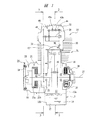
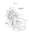
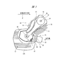
以下、本発明の実施の形態を図面に基づいて詳細に説明する。図1は車両用エンジンの一例を示す概略図であり、図2は図1における2−2線の方向から見たエンジンの概略図であり、図3は図1における3−3線の方向から見たエンジンの概略図である。 Hereinafter, embodiments of the present invention will be described in detail with reference to the drawings. 1 is a schematic view showing an example of a vehicle engine, FIG. 2 is a schematic view of the engine as seen from the direction of line 2-2 in FIG. 1, and FIG. 3 is from the direction of line 3-3 in FIG. It is the schematic of the seen engine.
このエンジン10は全地形走行車に搭載されるエンジンであり、図1に示すように、クランク軸11がクランクケース12に回転自在に装着され、クランクケース12は第1ケース体12aとこれに突き合わせて固定される第2ケース体12bとにより構成されている。クランクケース12の内部にはクランク室13が形成され、クランクケース12の底部はエンジンオイル14を収容するオイルパン15となっている。クランクケース12に設けられたシリンダ16にはピストン17が往復動自在に組み込まれ、ピストン17はコネクティングロッド18によりクランク軸11に連結され、ピストン17の直線往復動によりコネクティングロッド18を介してクランク軸11が回転駆動される。
This
図1に示すように、クランクケース12には発電体ケース19が取り付けられており、発電体ケース19内には発電体21が装着される。発電体21はクランク軸11に取り付けられるアウターロータ21aと、クランクケース12に仕切り板22を介して取り付けられるステータ21bとを有し、エンジン10が駆動されてクランク軸11が回転すると、発電体21により発電された電力が図示しないバッテリに充電される。
As shown in FIG. 1, a
バッテリから供給される電力により図示しないスタータモータが駆動されてエンジンを始動するようになっているが、バッテリの充電不足によってエンジン10をスタータモータにより始動させることができないときに、手動によりエンジン10を始動させるため、図1に示すように、発電体ケース19内にはリコイルスタータ23が設けられている。リコイルスタータ23は発電体ケース19に回転自在に装着されるリコイルプーリ24を有し、リコイルプーリ24に巻き付けられたリコイルロープ25を引き出してリコイルプーリ24を回転させると、リコイルプーリ24に組み込まれた係合部材がクランク軸11に係合してクランク軸11が回転され、エンジンを手動でも始動させることができる。
The starter motor (not shown) is driven by the electric power supplied from the battery to start the engine. However, when the
クランクケース12に固定されるカバー26には、図1に示すように、クランク軸11に同心状となって出力軸27が回転自在に装着されており、クランク軸11と出力軸27との間には遠心クラッチ28が組み込まれている。この遠心クラッチ28はクランク軸11の回転数が所定値以上となると、遠心力によって出力軸27とクランク軸11とを連結し、クランク軸11のトルクが出力軸27に伝達される。出力軸27のトルクは、図示しない変速機等の動力伝達装置を介して駆動輪に伝達される。
As shown in FIG. 1, the
シリンダ16にはシリンダヘッド30が取り付けられ、エンジン10はクランクケース12とシリンダ16とシリンダヘッド30とにより構成されるエンジン本体31に種々のエンジン構成部材を組み付けることにより組み立てられる。シリンダヘッド30にはロッカカバー32が取り付けられており、シリンダヘッド30には、図2に示すように、燃焼室33に開口して吸気ポート34と排気ポート35が形成され、吸気ポート34から燃焼室33に供給された混合気を点火するための点火プラグ36が、図1に示すように、燃焼室33に突出してシリンダヘッド30に取り付けられている。吸気ポート34を開閉する吸気弁37と排気ポート35を開閉する排気弁38がシリンダヘッド30に装着されており、クランク軸11の回転により吸気弁37と排気弁38とをクランク軸11の回転に同期して開閉駆動するために、図1および図3に示すようにシリンダヘッド30に回転自在に装着されたカムシャフト39とクランク軸11にはそれぞれスプロケット41とスプロケット42が固定され、これらのスプロケット41,42にはチェーン43が掛け渡されている。カムシャフト39が回転すると、ロッカシャフト44に設けられたロッカアーム45a,45bを介して吸気弁37と排気弁38とがそれぞれ開閉駆動される。このように、カムシャフト39、ロッカシャフト44およびロッカアーム45a,45b等により動弁機構46が形成されている。
A
図2示すように、クランク軸11に固定された駆動歯車11aに噛み合う被駆動歯車47aが固定されたポンプ駆動軸47が回転自在にクランクケース12に装着され、このポンプ駆動軸47は、図3に示すように、クランクケース12に組み込まれたオイルポンプ48に連結され、このオイルポンプ48により吸引されたエンジンオイル14は、クランク軸11に形成された油路を通ってクランクピンとコネクティングロッド18の嵌合面に供給され、クランクケース12に形成された油路を通ってピストン17とシリンダボアの摺動面に吹き付けられる。さらにエンジンオイル14は、遠心クラッチ28のクラッチシューにクランクケース12に形成された油路を介して供給され、動弁機構46のカムシャフト39等の潤滑油要求部に供給される。
As shown in FIG. 2, a
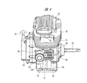
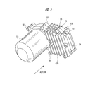
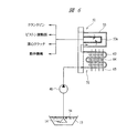
図4は図1〜図3に示したエンジン10の外観を示す正面図であり、図5は図4に示されたオイル冷却ユニットを拡大して示す斜視図であり、図6はオイル冷却ユニットを流れるエンジンオイルの油圧回路を示す概略図である。
4 is a front view showing an appearance of the
図4に示すように、エンジン本体31のクランクケース12には冷却ユニット51が取り付けられており、図2および図3に示されるように、冷却ユニット51はクランクケース12の車両進行方向Fの前面側に取り付けられている。この冷却ユニット51はオイルクーラ52を構成するとともにオイルフィルタ53が取り外し自在に装着されるようになっている。この冷却ユニット51には、図6に示すように、ストレーナ54を通ってオイルポンプ48に流入したエンジンオイル14が供給されるようになっており、エンジンオイル14はオイルクーラ52により冷却された後に、オイルフィルタ53のフィルタエレメント53aにより濾過されて潤滑油要求部に供給される。エンジンオイル14は、クランクピンとコネクティングロッド18の嵌合面に供給され、ピストン17とシリンダボアの摺動面に吹き付けられ、遠心クラッチ28のクラッチシューに供給され、さらに動弁機構46のカムシャフト39等の潤滑油要求部に供給される。
As shown in FIG. 4, a
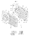
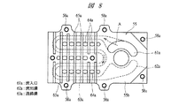
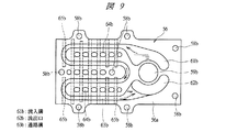
図7は冷却ユニット51を構成するベースプレート55と重合プレート56とを示す分解斜視図であり、図8はベースプレート55を図7における矢印8方向から見た正面図であり、図9は重合プレート56を図7における矢印9方向から見た正面図である。
7 is an exploded perspective view showing the
ベースプレート55はほぼ長方形となっており、内面には図7に示すように平坦な突き当て面55aが形成され、外面には図8に示すようにクランクケース12に取り付けられる平坦な取付面55bが長手方向約半分の領域に形成されている。重合プレート56はベースプレート55に対応した形状となっており、内面には図9に示すように平坦な突き当て面56aが形成され、外面には図7に示すようにフィルタケース嵌合孔57が形成されている。重合プレート56はその突き当て面56aをベースプレート55の突き当て面55aに、シート状のシール材を介して突き当ててベースプレート55に重ね合わされて、これら2枚のプレートにより冷却ユニット51が組み立てられる。ベースプレート55および重合プレート56は、それぞれアルミニウム合金等の軽合金を材料としてダイキャスト等により鋳造されている。
The
重合プレート56をベースプレート55に取り付けるために、ベースプレート55にはねじ孔58aが複数形成され、重合プレート56にはねじ孔58aに対応して貫通孔58bが形成されており、図4および図5に示すように、ねじ部材58をねじ孔58aにねじ結合することにより重合プレート56はベースプレート55に取り付けられる。全てのねじ部材58のうちいずれかのねじ部材がクランクケース12にねじ結合され、冷却ユニット51がクランクケース12に取り付けられる。
In order to attach the
ベースプレート55の取付面55bに対応させてその幅方向中央部には、図7および図8に示すように、オイルフィルタ53のフィルタ出口が取り付けられる円形の貫通孔59aが厚み方向に貫通して形成されており、この貫通孔59aを囲むようにしてベースプレート55には円弧状の流入口61aが厚み方向に貫通して形成されている。この流入口61aにはオイルポンプ48から吐出されたエンジンオイル14が図7に矢印Aで示すように流入するようになっている。この流入口61aに貫通孔59aを介して対向するように流出溝62aがベースプレート55の突き当て面55a側に形成されており、流出溝62aはベースプレート55の厚み方向には貫通することなく底面を有している。流入口61aと流出溝62aの間にはこれらを連通させる通路溝63aが蛇行して形成されており、図7に示すように、通路溝63aはベースプレート55の端部側に2つのターン部を有し、ベースプレート55の長手方向中央部に1つのターン部を有し、これらのターン部を介して連なる4つのストレート部が相互に平行となって長手方向に伸びている。
As shown in FIGS. 7 and 8, a circular through
重合プレート56には、図7および図9に示すように、ベースプレート55の貫通孔59aに対応させて貫通孔59bが形成され、流入口61aに対応させて流入溝61bが重合プレート56の突き当て面56aに形成されている。流入溝61bは重合プレート56の厚み方向には貫通しておらず底面を有している。重合プレート56には、さらに、ベースプレート55の流出溝62aに対応させて流出口62bが形成されており、この流出口62bは重合プレート56の厚み方向に貫通している。図9に示すように、流入溝61bと流出口62bとの間にはこれらを連通させる通路溝63bが通路溝63aに対向して突き当て面56aに形成されており、ベースプレート55と重合プレート56とをシール材を介して突き合わせると、両方の通路溝63a,63bにより、図6に示すように、オイルポンプ48から吐出されたエンジンオイル14をオイルフィルタ53に案内するオイル通路63が冷却ユニット51内に形成される。
As shown in FIGS. 7 and 9, the
ベースプレート55には、図8に示すように、通路溝63aのストレート部相互間に位置させて複数の通気孔64aが厚み方向に貫通して形成されており、通気孔64aは通路溝63aのストレート部に沿って所定の間隔置きに直線状に配列されている。それぞれの通気孔64aに対応させて重合プレート56には、図9に示すように、通気孔64bが形成されており、ベースプレート55と重合プレート56とを突き合わせると、それぞれの通気孔64a,64bにより冷却ユニット51を厚み方向に貫通する複数の通気通路64が図6に示すように形成される。
As shown in FIG. 8, the
図8に示すように、ベースプレート55の外面には、複数の放熱フィン65aが外方に突出するとともにベースプレート55の幅方向に延びて設けられており、同様に、重合プレート56にも、図7に示すように、複数の放熱フィン65bが設けられている。
As shown in FIG. 8, on the outer surface of the
冷却ユニット51はベースプレート55と重合プレート56の2枚のプレートをシール材を介して重ね合わせてねじ部材58により締結することにより形成され、冷却ユニット51にはオイルフィルタ53のケースを嵌合孔57に嵌合させるとともに、オイルフィルタ53のフィルタ出口を貫通孔59a,59bを貫通させてフィルタ出口に設けられた雄ねじをクランクケース12に形成されたねじ孔にねじ結合することにより、取り外し自在にオイルフィルタ53が装着される。このように、冷却ユニット51はオイルフィルタ53をクランクケース12に装着するための部材としても機能する。冷却ユニット51はクランクケース12の車両進行方向全面側に取り付けられるので、車両走行時には走行風が重合プレート55の外面に直接吹き付けられることになり、放熱フィン56bに流れるとともに通気孔64a,64bを貫通して冷却ユニット51とクランクケース12との間の隙間を通った後にクランクケース12に沿って流れる。これにより、冷却ユニット51内の相互に対向し合う通路溝63a,63bにより形成されるオイル通路63内を流れるエンジンオイル14は、走行風により冷却される冷却ユニット51により冷却され、冷却された後にオイルフィルタ53に流入して濾過される。
The cooling
このように、冷却ユニット51は2枚のプレートを重ね合わせることにより形成されているので、厚み寸法を大きくすることなく、放熱効率を高めることができるとともに、オイルフィルタ53を支持する構造となっているので、オイルフィルタ53と、オイルクーラ52とを接続するための配管やコネクターが不要となり、冷却ユニット51を簡単な構造として、その製造コストを低減することができる。
Thus, since the cooling
本発明は前記実施の形態に限定されるものではなく、その要旨を逸脱しない範囲で種々変更可能である。たとえば、実施の形態はバギー車つまり全地形走行車(ATV)用の空冷エンジンを示すが、二輪車等の他の車両用の空冷エンジンとしても本発明を適用することができる。また、通気孔64a,64bによる通気通路64は省略することも可能である。
The present invention is not limited to the above-described embodiment, and various modifications can be made without departing from the scope of the invention. For example, the embodiment shows an air-cooled engine for a buggy vehicle, that is, an all-terrain vehicle (ATV), but the present invention can also be applied to an air-cooled engine for other vehicles such as a motorcycle. Further, the
11 クランク軸
12 クランクケース
14 エンジンオイル
16 シリンダ
48 オイルポンプ
51 冷却ユニット
52 オイルクーラ
53 オイルフィルタ
55 ベースプレート
56 重合プレート
61a 流入口
61b 流入溝
62a 流出溝
62b 流出口
63 オイル通路
63a,63b 通路溝
64a,64b 通気孔
65a,65b 放熱フィン
11
Claims (2)
前記クランクケースに取り付けられるベースプレート、および当該ベースプレートに突き合わせて取り付けられるとともにオイルフィルタが装着される重合プレートを有し、
オイルポンプから吐出されたエンジンオイルが流入する流入口、エンジンオイルが流出する流出溝、および前記流入口と前記流出溝とを連通させる通路溝を前記ベースプレートに形成し、
前記流入口に対向する流入溝、前記流出溝に対向する流出口、および前記通路溝と対向してオイル通路を形成する通路溝を前記重合プレートに形成し、
前記ベースプレートおよび前記重合プレートに前記オイルフィルタのフィルタ出口が取り付けられる貫通孔を形成し、
前記ベースプレートおよび前記重合プレートにそれぞれ放熱フィンを設け、
前記オイル通路を形成するそれぞれの通路溝を前記ベースプレートと前記重合プレートのそれぞれに蛇行させて形成し、
前記ベースプレートと前記重合プレートのそれぞれに走行風が貫通する複数の通気孔を前記通路溝の相互間に位置させて厚み方向に貫通して形成することを特徴とする空冷エンジンのオイル冷却装置。 An oil cooling device for an air-cooled engine that cools engine oil stored in a crankcase that supports a crankshaft,
A base plate that is attached to the crankcase, and a polymerization plate that is attached to the base plate while being attached to the base plate and to which an oil filter is attached;
An inlet into which engine oil discharged from the oil pump flows in, an outflow groove through which engine oil flows out, and a passage groove that connects the inflow port with the outflow groove are formed in the base plate;
An inflow groove facing the inflow port, an outflow port facing the outflow groove, and a passage groove that forms an oil passage facing the passage groove are formed in the superposition plate,
Forming a through hole in which a filter outlet of the oil filter is attached to the base plate and the polymerization plate;
Each of the base plate and the overlapping plate is provided with heat radiation fins ,
Each passage groove forming the oil passage is formed to meander in each of the base plate and the polymerization plate,
Oil cooler for cooling the engine, characterized that you formed through by positioning in the thickness direction therebetween of the base plate and a plurality of vent holes the passage groove running wind passing through the each of the polymerization plate.
Priority Applications (2)
| Application Number | Priority Date | Filing Date | Title |
|---|---|---|---|
| JP2005100519A JP4494271B2 (en) | 2005-03-31 | 2005-03-31 | Oil cooling device for air cooling engine |
| US11/393,049 US7261080B2 (en) | 2005-03-31 | 2006-03-30 | Oil cooling system of an air-cooled engine |
Applications Claiming Priority (1)
| Application Number | Priority Date | Filing Date | Title |
|---|---|---|---|
| JP2005100519A JP4494271B2 (en) | 2005-03-31 | 2005-03-31 | Oil cooling device for air cooling engine |
Publications (2)
| Publication Number | Publication Date |
|---|---|
| JP2006283565A JP2006283565A (en) | 2006-10-19 |
| JP4494271B2 true JP4494271B2 (en) | 2010-06-30 |
Family
ID=37068836
Family Applications (1)
| Application Number | Title | Priority Date | Filing Date |
|---|---|---|---|
| JP2005100519A Expired - Fee Related JP4494271B2 (en) | 2005-03-31 | 2005-03-31 | Oil cooling device for air cooling engine |
Country Status (2)
| Country | Link |
|---|---|
| US (1) | US7261080B2 (en) |
| JP (1) | JP4494271B2 (en) |
Families Citing this family (17)
| Publication number | Priority date | Publication date | Assignee | Title |
|---|---|---|---|---|
| US20090038580A1 (en) * | 2007-08-06 | 2009-02-12 | Irp,Llc | Oil cooler for motor vehicles |
| US8102230B2 (en) * | 2007-10-12 | 2012-01-24 | Eriksen Electric Power Systems As | Inductive coupler connector |
| EP2090499A1 (en) * | 2008-01-25 | 2009-08-19 | GM Global Technology Operations, Inc. | Engine cover with coolings fins |
| JP5100527B2 (en) * | 2008-06-18 | 2012-12-19 | 本田技研工業株式会社 | Engine oil filter device |
| JP4892531B2 (en) * | 2008-09-17 | 2012-03-07 | 本田技研工業株式会社 | Oil passage structure for cooling in vehicle engine |
| US8375917B1 (en) | 2009-07-23 | 2013-02-19 | Gene Neal | Engine oil cooler |
| US20120090811A1 (en) * | 2010-10-19 | 2012-04-19 | E & D Holdings, LLC | Oil cooler assembly |
| US9132464B2 (en) | 2012-06-12 | 2015-09-15 | Martinrea Industries, Inc. | Method for hot stamping metal |
| CN104033206A (en) * | 2014-06-13 | 2014-09-10 | 重庆隆鑫发动机有限公司 | Engine oil radiating structure for internal combustion engine |
| CN104929728A (en) * | 2015-06-29 | 2015-09-23 | 金坛鑫田柴油机有限公司 | Roundabout cooling and filtering type engine oil cooler |
| JP6646569B2 (en) * | 2016-12-28 | 2020-02-14 | 株式会社クボタ | engine |
| US10428705B2 (en) * | 2017-05-15 | 2019-10-01 | Polaris Industries Inc. | Engine |
| US10550754B2 (en) | 2017-05-15 | 2020-02-04 | Polaris Industries Inc. | Engine |
| CN111213024A (en) | 2017-10-26 | 2020-05-29 | 康明斯公司 | Cooled lubricant filter housing |
| USD904227S1 (en) | 2018-10-26 | 2020-12-08 | Polaris Industries Inc. | Headlight of a three-wheeled vehicle |
| US11635005B2 (en) | 2020-08-21 | 2023-04-25 | RB Distribution, Inc. | Oil filter assembly |
| US12078090B1 (en) | 2024-02-29 | 2024-09-03 | Skyward Automotive Products LLC | Oil filter housing and assembly |
Family Cites Families (9)
| Publication number | Priority date | Publication date | Assignee | Title |
|---|---|---|---|---|
| US3800868A (en) * | 1972-04-14 | 1974-04-02 | Curtiss Wright Corp | Heat exchanger |
| JP2803206B2 (en) * | 1989-08-25 | 1998-09-24 | スズキ株式会社 | Lubricating oil cooling system for motorcycle engines |
| JPH04107430U (en) * | 1991-02-27 | 1992-09-17 | 三菱自動車工業株式会社 | Oil pan |
| JPH05215203A (en) * | 1992-01-31 | 1993-08-24 | Suzuki Motor Corp | Automatic transmission |
| US5351664A (en) * | 1993-04-16 | 1994-10-04 | Kohler Co. | Oil cooling device |
| JP2807873B2 (en) | 1996-05-02 | 1998-10-08 | 本田技研工業株式会社 | Automotive oil cooler |
| JP3059421B2 (en) * | 1998-09-14 | 2000-07-04 | 本田技研工業株式会社 | Motorcycle |
| JP2002225574A (en) | 2001-02-01 | 2002-08-14 | Fuji Heavy Ind Ltd | Air-cooled engine cooling structure |
| JP4354252B2 (en) * | 2002-10-29 | 2009-10-28 | 川崎重工業株式会社 | Oil cooler and small ship |
-
2005
- 2005-03-31 JP JP2005100519A patent/JP4494271B2/en not_active Expired - Fee Related
-
2006
- 2006-03-30 US US11/393,049 patent/US7261080B2/en not_active Expired - Fee Related
Also Published As
| Publication number | Publication date |
|---|---|
| JP2006283565A (en) | 2006-10-19 |
| US20060219208A1 (en) | 2006-10-05 |
| US7261080B2 (en) | 2007-08-28 |
Similar Documents
| Publication | Publication Date | Title |
|---|---|---|
| JP4494271B2 (en) | Oil cooling device for air cooling engine | |
| US9638070B2 (en) | Engine | |
| JP4732375B2 (en) | Forced air-cooled internal combustion engine | |
| JP5022355B2 (en) | Water pump mounting structure for water-cooled internal combustion engine | |
| EP2893178B1 (en) | Internal combustion engine having a split crankcase | |
| KR100342968B1 (en) | Swing-typed power unit | |
| JP2007177676A (en) | Air-cooled internal combustion engine having a sensor for detecting engine state | |
| JP3942675B2 (en) | Fluid pump structure in internal combustion engine | |
| KR100367974B1 (en) | Swing-typed power unit | |
| EP2620612B1 (en) | Internal combustion engine and straddle-type vehicle including the same | |
| CN1991148B (en) | Air cooling internal combustion engine with oil temperature sensor | |
| ITTO20060006A1 (en) | INTERNAL COMBUSTION ENGINE. | |
| KR100688221B1 (en) | Auxiliary structure for internal combustion engine | |
| EP2354511B1 (en) | Water-cooled four-cycle engine | |
| TWI551775B (en) | Forced air-cooling type internal combustion engine and saddled vehicle having the same | |
| EP2354512B1 (en) | Water-cooled four-cycle engine | |
| TWI296670B (en) | ||
| JP4937150B2 (en) | Internal combustion engine | |
| WO2003095868A1 (en) | Vehicle with continuously variable transmission | |
| JP2005180261A (en) | Cooling structure for hybrid vehicle power unit | |
| JP2006250128A (en) | Air-cooled engine cylinder head | |
| JP5091754B2 (en) | Cylinder block and engine including cylinder block | |
| JP2001241310A (en) | Four-stroke engine oil pump layout | |
| JP2004011505A (en) | Lubricating oil supply structure of internal combustion engine | |
| JP5135365B2 (en) | Water-cooled four-cycle engine |
Legal Events
| Date | Code | Title | Description |
|---|---|---|---|
| A621 | Written request for application examination |
Free format text: JAPANESE INTERMEDIATE CODE: A621 Effective date: 20071002 |
|
| A977 | Report on retrieval |
Free format text: JAPANESE INTERMEDIATE CODE: A971007 Effective date: 20091218 |
|
| A131 | Notification of reasons for refusal |
Free format text: JAPANESE INTERMEDIATE CODE: A131 Effective date: 20100105 |
|
| A521 | Request for written amendment filed |
Free format text: JAPANESE INTERMEDIATE CODE: A523 Effective date: 20100225 |
|
| TRDD | Decision of grant or rejection written | ||
| A01 | Written decision to grant a patent or to grant a registration (utility model) |
Free format text: JAPANESE INTERMEDIATE CODE: A01 Effective date: 20100323 |
|
| A01 | Written decision to grant a patent or to grant a registration (utility model) |
Free format text: JAPANESE INTERMEDIATE CODE: A01 |
|
| A61 | First payment of annual fees (during grant procedure) |
Free format text: JAPANESE INTERMEDIATE CODE: A61 Effective date: 20100407 |
|
| R150 | Certificate of patent or registration of utility model |
Free format text: JAPANESE INTERMEDIATE CODE: R150 |
|
| FPAY | Renewal fee payment (event date is renewal date of database) |
Free format text: PAYMENT UNTIL: 20130416 Year of fee payment: 3 |
|
| FPAY | Renewal fee payment (event date is renewal date of database) |
Free format text: PAYMENT UNTIL: 20130416 Year of fee payment: 3 |
|
| FPAY | Renewal fee payment (event date is renewal date of database) |
Free format text: PAYMENT UNTIL: 20140416 Year of fee payment: 4 |
|
| R250 | Receipt of annual fees |
Free format text: JAPANESE INTERMEDIATE CODE: R250 |
|
| S531 | Written request for registration of change of domicile |
Free format text: JAPANESE INTERMEDIATE CODE: R313531 |
|
| R350 | Written notification of registration of transfer |
Free format text: JAPANESE INTERMEDIATE CODE: R350 |
|
| R250 | Receipt of annual fees |
Free format text: JAPANESE INTERMEDIATE CODE: R250 |
|
| R250 | Receipt of annual fees |
Free format text: JAPANESE INTERMEDIATE CODE: R250 |
|
| R250 | Receipt of annual fees |
Free format text: JAPANESE INTERMEDIATE CODE: R250 |
|
| S533 | Written request for registration of change of name |
Free format text: JAPANESE INTERMEDIATE CODE: R313533 |
|
| R350 | Written notification of registration of transfer |
Free format text: JAPANESE INTERMEDIATE CODE: R350 |
|
| LAPS | Cancellation because of no payment of annual fees |