EP3342687A1 - Bodywork part comprising an opening adapted to receive a hatch - Google Patents
Bodywork part comprising an opening adapted to receive a hatch Download PDFInfo
- Publication number
- EP3342687A1 EP3342687A1 EP17207894.1A EP17207894A EP3342687A1 EP 3342687 A1 EP3342687 A1 EP 3342687A1 EP 17207894 A EP17207894 A EP 17207894A EP 3342687 A1 EP3342687 A1 EP 3342687A1
- Authority
- EP
- European Patent Office
- Prior art keywords
- hatch
- opening
- lug
- face
- protuberance
- Prior art date
- Legal status (The legal status is an assumption and is not a legal conclusion. Google has not performed a legal analysis and makes no representation as to the accuracy of the status listed.)
- Granted
Links
- 230000002093 peripheral effect Effects 0.000 claims abstract description 37
- 238000003908 quality control method Methods 0.000 claims abstract description 4
- 230000000717 retained effect Effects 0.000 claims description 4
- 238000005096 rolling process Methods 0.000 claims description 3
- 238000005253 cladding Methods 0.000 claims 1
- 238000006073 displacement reaction Methods 0.000 claims 1
- 230000001154 acute effect Effects 0.000 description 13
- 230000005489 elastic deformation Effects 0.000 description 3
- 241000826860 Trapezium Species 0.000 description 2
- 230000000295 complement effect Effects 0.000 description 2
- 238000000034 method Methods 0.000 description 2
- 239000007787 solid Substances 0.000 description 2
- 239000011248 coating agent Substances 0.000 description 1
- 238000000576 coating method Methods 0.000 description 1
- 230000000694 effects Effects 0.000 description 1
- 230000002427 irreversible effect Effects 0.000 description 1
- 238000012423 maintenance Methods 0.000 description 1
- 239000012528 membrane Substances 0.000 description 1
- 238000003825 pressing Methods 0.000 description 1
- 230000002441 reversible effect Effects 0.000 description 1
- 238000010998 test method Methods 0.000 description 1
Images


Classifications
-
- B—PERFORMING OPERATIONS; TRANSPORTING
- B60—VEHICLES IN GENERAL
- B60R—VEHICLES, VEHICLE FITTINGS, OR VEHICLE PARTS, NOT OTHERWISE PROVIDED FOR
- B60R19/00—Wheel guards; Radiator guards, e.g. grilles; Obstruction removers; Fittings damping bouncing force in collisions
- B60R19/02—Bumpers, i.e. impact receiving or absorbing members for protecting vehicles or fending off blows from other vehicles or objects
- B60R19/023—Details
-
- B—PERFORMING OPERATIONS; TRANSPORTING
- B62—LAND VEHICLES FOR TRAVELLING OTHERWISE THAN ON RAILS
- B62D—MOTOR VEHICLES; TRAILERS
- B62D25/00—Superstructure or monocoque structure sub-units; Parts or details thereof not otherwise provided for
- B62D25/24—Superstructure sub-units with access or drainage openings having movable or removable closures; Sealing means therefor
Definitions
- the present invention relates to a bodywork part having an opening adapted to receive a hatch, to a trim assembly comprising such a bodywork part and to a quality test method of such an assembly.
- Such a body part is for example a bumper skin, intended to be arranged opposite a bumper beam front or rear of a motor vehicle.
- Motor vehicles comprising, at the front or rear, a towing ring hidden by a bumper skin.
- An opening is provided in the bodywork part to provide access to the towing eye, so as to be able to tow the motor vehicle in case of failure.
- the opening of the bodywork part is closed by a removable hatch.
- the hatch is retained in the closed position on the bodywork part by at least one latching mechanism, so that the hatch is sufficiently maintained in the opening, but removable.
- the visible face of the hatch must be flush with the visible face of the bodywork part.
- an arrangement of the hatch and the bodywork piece such as a lever force can be exerted on the hatch, around a substantially transverse axis, to tilt disassembly position for its removal.
- Such a hatch accumulates a retaining clip and at least one lug, whose action combines with that of the clip so that the force required to disassemble the hatch is greater than that required to put it in place.
- An object of the present invention is to eliminate the above disadvantages by providing, at lower cost, a bodywork part having an opening adapted to receive a hatch, with a flush position of the hatch on the bodywork part which remains satisfactory despite repeated assembly and disassembly of the hatch.
- Another purpose is to provide a snap-on door whose snap-fastening means are not fragile.
- the object of the invention is a bodywork part having a visible face, said part comprising an opening delimited by a reentrant peripheral rim extending the visible face towards the inside of the opening, a portion of the peripheral rim forming a base for a lug having a projection protruding from said peripheral rim, the body part being characterized in that the base of the lug comprises two thin portions of the peripheral rim, located on either side of the protuberance of the lug and conferring on the base an ability to deform elastically by retracting the protuberance of the lug.
- the hatch can maintain a flush position on the bodywork part, because the lug on the peripheral edge of the opening to help the positioning of the flush hatch recovers and returns to position thanks to the reversible elastic deformations of the base of the ergot.
- the fatigue of the ergot base is less than that of the ergot of the state of the art because the thinned portions of the peripheral edge of the opening allow an elastic deformation of this edge, deformation which allows the base of the lug to retract the protuberance of the lug to release the hatch during assembly and disassembly.
- the protrusion of the lug does not have to be flexible - although this stiffness characteristic is not necessary according to the invention - so that the lug can be relatively solid and solid, which protects it risks of breakage or irreversible deformation.
- the peripheral rim has an inner face defining the opening and an outer face opposite to the inner face and each thinned portion of the rim only results from a recess of the outer face.
- the inner face of the rim which is potentially visible for an attentive observer who scrutinizes the clearance between the hatch and the peripheral edge of the opening, shows no variation in thickness because the troughs of the peripheral edge are found only on the outer face of said peripheral edge, which is turned towards the inside of the bodywork part, in a perfectly invisible zone if the bodywork part is mounted on the vehicle.
- the bodywork part comprises at least two bases, each for a lug having a projection protruding from the peripheral rim.
- These two bases can be arranged symmetrically with respect to each other, to take account of a symmetry of shape of the opening, for example if the latter is trapezoidal and it is preferable to have two pins on two sides of the trapezium to ensure the symmetry of the maintenance in outcrop, rather than a single lug that would be located in an angle of the trapezium.
- the bodywork part comprises at least one bearing surface extending towards the inside of the opening, over part of the contour of the opening and away from the visible face.
- the body part comprises, diametrically opposed on the contour of the opening and recessed from the visible face, two bumps arranged to form together a rolling surface defining a substantially parallel pivot axis on the visible side.
- Such a pivot axis is known and allows the hatch engages, respectively emerges from the opening by a movement comprising a pivoting of the hatch to respectively from its outcropping position.
- the two bumps materialize a surface on which the hatch tilts during this pivoting.
- a particularly advantageous application of the invention is that the bodywork part is a bumper skin.
- the present invention also relates to a trim assembly comprising a bodywork part as described above and a hatch having a visible face, the hatch being movable between a flush position in which the hatch is retained by the lug with the visible face of the hatch and the visible face of the flush bodywork and misalignment positions in which the hatch pushes the lug with the visible face of the hatch and the visible face of the piece of body unclamping, characterized in that the base of the lug is able to deform elastically by retracting the protuberance of the lug when the flap passes into the positions of misalignment and to return to its shape by elastic return when the hatch is located more in the positions of misalignment.
- the hatch comprises an edge provided with an inclined plane serving to support the protuberance of the lug in the flush position of the hatch.
- the contact between the hatch and the protrusion of the lug occurs along a line of contact, which is preferable to a contact between two surfaces whose parallelism is never guaranteed.
- the contact line is in a relatively central zone of the inclined plane, that is to say at a distance from the edges between this inclined plane and the edge of the hatch, so that the edge possibly visible, for a very attentive observer, of the hatch, can not present any mark of wear due to the support of the protuberance of the pin.
- the hatch comprises at least one clip adapted to snap against an inner face of the bodywork part when the hatch is in the outcropping position.
- a clip ensures, as a main thing, fastening of the hatch on the bodywork part, possibly with the help of the support pad.
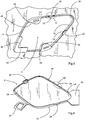
- a front bumper skin 2 which is a body part of a motor vehicle, is shown in the figures.
- This bumper skin 2 is intended to be fixed on a body of a motor vehicle, facing a front or rear bumper beam (not shown).
- This bumper skin 2 has a visible face 4 from the outside with a satisfactory exterior aesthetic appearance, in line with the expectations of car manufacturers.
- the body part 2 can be indifferently any bodywork part of a motor vehicle, in accordance with the execution of the invention.
- the bumper skin 2 has an opening 6 intended to give access to at least one component located in the box facing the opening 6, in particular a towing ring (not shown).
- the opening 6 is configured to be obscured by a hatch 8, for aesthetic purposes, but also to optimize the aerodynamics of the vehicle.
- This opening 6 is through. It therefore opens on the visible side 4 and on an opposite face of the bumper skin 2, not visible to an observer outside the vehicle.
- the opening 6 has a substantially trapezoidal shape.
- the opening 6 has a shape comprising at least one acute angle. It will be noted that the opening 6 and the hatch 8 are of substantially complementary shapes.
- the hatch 8 has a visible face 12 for an observer located outside, intended to seal the opening 6, or to make it invisible for a casual observer.
- the visible face of the hatch 12 and the visible face 4 of the bumper skin 2 have the same aesthetic appearance, that is to say the same coating and / or the same surface state.
- various alternative embodiments are possible and that it is possible to envisage, without limitation, a visible face 12 of the hatch 8 having a different appearance from the visible face 4 of the bumper skin 2.
- the visible face 12 of the hatch 8 is flush with the visible face 4 of the bumper skin 2, to give satisfactory aesthetics and aerodynamics.
- the bumper skin 2 comprises a peripheral rim 14 peripheral to the opening 6.
- This peripheral rim 14 extends the visible face 4 towards the inside of the opening 6.
- the rim 14 has an inner face 16 delimiting the opening 6 and an outer face 18 opposite the inner face 16.
- This peripheral flange 14 comprises two bases 20 each supporting a protrusion 22 of a lug. This protrusion 22 projects from the peripheral rim 14 towards the inside of the opening 6.
- the protrusion 22 comprises a ridge 24 adapted to bear against the hatch 8, in particular against a peripheral edge 26 of the hatch 8.
- the edge 26 of the hatch 8 has a notch 28, inside which the edge 26 is cut in an inclined plane 30 which serves to support the edge 24 of the protrusion 22, as one see him on the figures 7 and 9 .
- the contact between the hatch 8 and the protrusion 22 of the lug occurs at the top of the edge 24, along a line of contact 32.
- This line of contact 32 is in a relatively central area of the plane inclined 30, that is to say at a distance from the visible faces 12 and invisible of the hatch 8, so that an edge 34 (between the edge 26 and the inclined plane 30), possibly visible to a very attentive observer, can not present any wear mark due to the support of the protuberance 22 of the lug.
- the two lugs 20-22 are located on two opposite edges of the opening 8 forming a first acute angle 36 of this opening 8.
- Each base 20 comprises two thinned portions 38 of the peripheral rim 14, located on either side of the protrusion 22.
- Each thinned portion 38 provides flexibility to the base 20, allowing it to deform and retract the protrusion 22 of ergot, under conditions that will be described further.
- Each thinned portion 38 of the flange 14 results from the presence of a recess 40 opening laterally and on the outer face 18 of the peripheral flange 14.
- the recesses 40 are present only on the outer face of the flange 18, so that the inner face 16 the peripheral rim 14 has a regular aesthetic appearance, without reliefs. It is understood that each thinned portion 38 is flexible and deformable due to its small thickness, less than the thickness of the flange 14 to the right of the lug 22 and outside the base 20.
- Each thinned portion 38 forms a blade or flexible membrane with spring or elastic effect.
- the base 20 is capable of deforming elastically when it receives a bias, to retract the protuberance 22 of the lug, and to return to its original shape by springback when this solicitation ceases.
- the bumper skin 2 also comprises a first bearing surface 42 along the peripheral edge 14, in a second acute angle 44 opposite the first acute angle 36.
- the bearing surface 42 is positioned slightly behind the opening 6, towards the inside of the bumper skin 2, to serve as support for the hatch 8 while keeping the latter flush, that is to say with its visible outer face 12 extending the visible outer face 4 bumper skin 2.
- Two other beaches 46 are present in the two obtuse angles 48 of the opening 6.
- Each of the beaches 46 carries a bump 50.
- the two bumps 50 are substantially parallel to each other and materialize a rolling surface for the hatch 8 which thus switches around. of a pivot axis 52 when it is placed on the opening 6 and its withdrawal from the opening 6, as described for example in the document US8985661B2 .
- the tops of the bumps 50 are supported on the non-visible inner face of the hatch, inside its edge 26. When pivoting the hatch 8, the inner face of the hatch rolls or tilts on the bumps 50, between its outcrop position and one of the misalignment positions in which it has one half tucked into the bumper skin and one half out of the bumper skin.
- the hatch 8 has substantially the same trapezoidal shape as the opening 6.
- the hatch 8 At a first acute angle 54, intended to join the first acute angle 36 of the opening 6, the hatch 8 comprises a tail 56 of flat shape intended to bear against the end of the peripheral edge 14 of the opening, to retain the hatch in flush position by preventing it from leaving the opening 6.
- Another acute angle 58 of the hatch 8 is intended to join the second acute angle 44 of the opening 6. At this point, the flush position of the hatch 8 is provided by pressing the edge 26 of the hatch 8 against the bearing area 42.
- the hatch 8 comprises a retaining clip 60 which is shaped to fit at the end of the peripheral rim 14 of the opening, close to the support pad 42, so as to maintain the hatch 8 in support against the support surface 42.
- the figure 9 summarizes the entire device for holding the hatch 8 in the outcropping position, through an IX-IX cutting line comprising three planes P1, P2 and P3. The parts or parts of parts visible in these three planes are included in the intervals P1, P2 and P3 on the figure 9 .
- the protuberances 22 of the pins play the complementary role of keeping the tail 56 bearing against the peripheral edge 14 of the opening 6, by pushing the 8 door to the outside of the bumper skin 2, thanks to the inclined plane 30 on which bears the edge 24 of the protrusion 22, as explained above.
- the hatch 8 is mounted movably between a flush position in which the hatch 8 is retained by the lug 20-22 with the visible face of the hatch 12 and the visible face of the flush bodywork piece 4 and positions of misalignment in which the hatch 8 pushes the pin 20-22 with the visible face of the hatch 12 and the visible face of the bodywork part 4 unclamping.
- the hatch 8 and the bumper skin 2 constitute a dressing unit.
- the covering assembly may also comprise any snap fastening means, possibly different from the clip 60, offering optimal positioning in the outcropping position and / or safety means such as a tongue 62 intended to wedge in a notch (not shown) of the bumper skin 2, so as to avoid the loss of the hatch 8 when disassembled.
- these means can be arranged on the bodywork part 2 and / or on the hatch 8.
- the hatch 8 occupies its flush position closing the opening 6.
- a user and / or a person responsible for performing a quality control of the assembly pushes on the hatch 8 from the outside to the inside of the vehicle in the vicinity of the first acute angle 36.
- the hatch tilts on the bumps 50 about the pivot axis 52 by sinking into the opening 6 in the acute angle 36 and protruding from the opening 6 in the 44.
- the inclined planes 30 push back the edges 24 of the protuberances 22.
- the bases 20 then deform elastically by retracting the protuberances 22.
- the hatch 8 is then in an intermediate position called "half-in-half-out", in which one half of the hatch 8 (that located on the side of the angle 36 relative to the pivot axis 52) enters the bumper skin 2, while the other half (that located on the side of the angle 44 relative to the pivot axis 52) comes out.
- the hatch 8 can then be extracted from the opening.
- the user grasps the hatch 8 and introduces it obliquely into the "half-in-half-out" position, which has just been described.
- the user pushes on the hatch 8 in the vicinity of the second acute angle 44 to pivotally press against the bearing pad 42.
- the inclined planes 30 bear on the protuberances 22 and spread them slightly, if necessary.
- the elastic deformation of the bases 20 allows this recoil of the protuberances 22.
- the clip 60 snaps and the lugs 20-22, bearing against the inclined planes 30, provide, by elastic return of their base 20, bringing into contact the tail 56 with the peripheral edge 14 of the opening 6.
- the hatch 8 returns to its flush position in the opening 6.
- the invention has the advantage that the above operations can be repeated at least five times without irreversibly deforming or breaking at least part of the assembly.
- the user and / or the person in charge of performing a quality control of the assembly performs a simple operation requiring no tools and very little effort to assemble and disassemble the hatch 8 in the opening 6 of the bumper skin 2. Because of the particular configuration of the invention, the mounting and dismounting operation of the hatch 8 does not damage the hatch 8 or the bodywork part 2 and offers a flush positioning with a satisfactory aesthetic appearance, preferably throughout the life of the motor vehicle.
Landscapes
- Engineering & Computer Science (AREA)
- Mechanical Engineering (AREA)
- Chemical & Material Sciences (AREA)
- Combustion & Propulsion (AREA)
- Transportation (AREA)
- Snaps, Bayonet Connections, Set Pins, And Snap Rings (AREA)
- Superstructure Of Vehicle (AREA)
- Connection Of Plates (AREA)
- Vehicle Interior And Exterior Ornaments, Soundproofing, And Insulation (AREA)
Abstract
Pièce de carrosserie (2) ayant une face visible (4), ladite pièce (2) comportant une ouverture (6) délimitée par un rebord périphérique rentrant (14) prolongeant la face visible (4) vers l'intérieur de l'ouverture (6), une portion du rebord périphérique (14) formant une base pour un ergot ayant une protubérance (22) en saillie dudit rebord périphérique (14), caractérisée en ce que la base de l'ergot comprend deux portions amincies du rebord périphérique (14), situées de part et d'autre de la protubérance (22) de l'ergot et conférant à la base une aptitude à se déformer élastiquement en escamotant la protubérance (22) de l'ergot.
Ensemble d'habillage comprenant une pièce de carrosserie (2) et une trappe. Procédé de contrôle qualité d'un tel ensemble.

A trim assembly comprising a body part (2) and a hatch. Quality control method of such an assembly.
Description
La présente invention est relative à une pièce de carrosserie comportant une ouverture apte à recevoir une trappe, à un ensemble d'habillage comportant une telle pièce de carrosserie et à un procédé de test de qualité d'un tel ensemble.The present invention relates to a bodywork part having an opening adapted to receive a hatch, to a trim assembly comprising such a bodywork part and to a quality test method of such an assembly.
Une telle pièce de carrosserie est par exemple une peau de pare-chocs, destinée à être disposée en regard d'une poutre de pare-chocs avant ou arrière de véhicule automobile.Such a body part is for example a bumper skin, intended to be arranged opposite a bumper beam front or rear of a motor vehicle.
On connait des véhicules automobiles comprenant, à l'avant ou à l'arrière, un anneau de remorquage caché par une peau de pare-chocs. Une ouverture est ménagée dans la pièce de carrosserie pour offrir un accès à l'anneau de remorquage, de manière à pouvoir remorquer le véhicule automobile en cas de panne.Motor vehicles are known comprising, at the front or rear, a towing ring hidden by a bumper skin. An opening is provided in the bodywork part to provide access to the towing eye, so as to be able to tow the motor vehicle in case of failure.
Dans un but esthétique, l'ouverture de la pièce de carrosserie est fermée par une trappe amovible. Classiquement, la trappe est retenue en position d'obturation sur la pièce de carrosserie par au moins un mécanisme d'encliquetage, de façon à ce que la trappe soit suffisamment maintenue dans l'ouverture, mais démontable. Dans cette position d'obturation de la trappe, la face visible de la trappe doit affleurer la face visible de la pièce de carrosserie. Pour ce faire, il est connu, par exemple de
Une telle solution ne donne pas entièrement satisfaction. En effet, on constate dans la pratique que l'ergot est trop sollicité à la déformation et se détériore à l'usage. L'ergot, déformé ou cassé, ne peut plus remplir sa fonction et la trappe quitte facilement la position d'affleurement.Such a solution is not entirely satisfactory. Indeed, it is found in practice that the lug is too stressed to the deformation and deteriorates with use. The lug, deformed or broken, can no longer perform its function and the hatch easily leaves the outcrop position.
Un but de la présente invention est de supprimer les inconvénients ci-dessus en fournissant, à moindre coût, une pièce de carrosserie comportant une ouverture apte à recevoir une trappe, avec un positionnement d'affleurement de la trappe sur la pièce de carrosserie qui demeure satisfaisant malgré des montages et démontages répétés de la trappe.An object of the present invention is to eliminate the above disadvantages by providing, at lower cost, a bodywork part having an opening adapted to receive a hatch, with a flush position of the hatch on the bodywork part which remains satisfactory despite repeated assembly and disassembly of the hatch.
Un autre but est de fournir une trappe encliquetable dont les moyens d'encliquetage ne sont pas fragiles.Another purpose is to provide a snap-on door whose snap-fastening means are not fragile.
A cet effet, l'invention a pour objet une pièce de carrosserie ayant une face visible, ladite pièce comportant une ouverture délimitée par un rebord périphérique rentrant prolongeant la face visible vers l'intérieur de l'ouverture, une portion du rebord périphérique formant une base pour un ergot ayant une protubérance en saillie dudit rebord périphérique, la pièce de carrosserie étant caractérisée en ce que la base de l'ergot comprend deux portions amincies du rebord périphérique, situées de part et d'autre de la protubérance de l'ergot et conférant à la base une aptitude à se déformer élastiquement en escamotant la protubérance de l'ergot.For this purpose, the object of the invention is a bodywork part having a visible face, said part comprising an opening delimited by a reentrant peripheral rim extending the visible face towards the inside of the opening, a portion of the peripheral rim forming a base for a lug having a projection protruding from said peripheral rim, the body part being characterized in that the base of the lug comprises two thin portions of the peripheral rim, located on either side of the protuberance of the lug and conferring on the base an ability to deform elastically by retracting the protuberance of the lug.
Grâce à l'invention, la trappe peut conserver un positionnement affleurant sur la pièce de carrosserie, car l'ergot présent sur le bord périphérique de l'ouverture pour aider au positionnement de la trappe à l'affleurement s'escamote et revient en position grâce aux déformations élastiques réversibles de la base de l'ergot. La fatigue de la base de l'ergot est moindre que celle de l'ergot de l'état de la technique car les portions amincies du bord périphérique de l'ouverture autorisent une déformation élastique de ce bord, déformation qui permet à la base de l'ergot d'escamoter la protubérance de l'ergot pour libérer la trappe lors de son montage et de son démontage. De plus, la protubérance de l'ergot n'a pas à être souple - bien que cette caractéristique de rigidité ne soit pas nécessaire selon l'invention -, de sorte que l'ergot peut être relativement massif et solide, ce qui le protège des risques de cassure ou de déformation irréversible.Thanks to the invention, the hatch can maintain a flush position on the bodywork part, because the lug on the peripheral edge of the opening to help the positioning of the flush hatch recovers and returns to position thanks to the reversible elastic deformations of the base of the ergot. The fatigue of the ergot base is less than that of the ergot of the state of the art because the thinned portions of the peripheral edge of the opening allow an elastic deformation of this edge, deformation which allows the base of the lug to retract the protuberance of the lug to release the hatch during assembly and disassembly. In addition, the protrusion of the lug does not have to be flexible - although this stiffness characteristic is not necessary according to the invention - so that the lug can be relatively solid and solid, which protects it risks of breakage or irreversible deformation.
Dans un mode de réalisation particulier de l'invention, le rebord périphérique présente une face intérieure délimitant l'ouverture et une face extérieure opposée à la face intérieure et chaque portion amincie du rebord résulte uniquement d'un évidement de la face extérieure.In a particular embodiment of the invention, the peripheral rim has an inner face defining the opening and an outer face opposite to the inner face and each thinned portion of the rim only results from a recess of the outer face.
Ainsi, la face intérieure du rebord, qui est potentiellement visible pour un observateur attentif qui scruterait le jeu entre la trappe et le bord périphérique de l'ouverture, ne montre aucune variation d'épaisseur, car les creux du bord périphérique ne se trouvent que sur la face extérieure dudit bord périphérique, laquelle est tournée vers l'intérieur de la pièce de carrosserie, en zone parfaitement invisible si la pièce de carrosserie est montée sur le véhicule.Thus, the inner face of the rim, which is potentially visible for an attentive observer who scrutinizes the clearance between the hatch and the peripheral edge of the opening, shows no variation in thickness because the troughs of the peripheral edge are found only on the outer face of said peripheral edge, which is turned towards the inside of the bodywork part, in a perfectly invisible zone if the bodywork part is mounted on the vehicle.
Dans un mode de réalisation avantageux, la pièce de carrosserie comprend au moins deux bases, chacune pour un ergot ayant une protubérance en saillie du rebord périphérique. Ces deux bases peuvent être disposées symétriquement l'une par rapport à l'autre, pour tenir compte d'une symétrie de forme de l'ouverture, par exemple si cette dernière est trapézoïdale et qu'il est préférable de disposer deux ergots sur deux côtés du trapèze pour assurer la symétrie du maintien en affleurement, plutôt qu'un seul ergot qui serait localisé dans un angle du trapèze.In an advantageous embodiment, the bodywork part comprises at least two bases, each for a lug having a projection protruding from the peripheral rim. These two bases can be arranged symmetrically with respect to each other, to take account of a symmetry of shape of the opening, for example if the latter is trapezoidal and it is preferable to have two pins on two sides of the trapezium to ensure the symmetry of the maintenance in outcrop, rather than a single lug that would be located in an angle of the trapezium.
Dans un mode de réalisation de l'invention, la pièce de carrosserie comprend au moins une plage d'appui s'étendant vers l'intérieur de l'ouverture, sur une partie du contour de l'ouverture et en retrait de la face visible.In one embodiment of the invention, the bodywork part comprises at least one bearing surface extending towards the inside of the opening, over part of the contour of the opening and away from the visible face. .
Cette plage d'appui est connue dans l'état de la technique, par exemple dans le document déjà cité
Dans un mode de réalisation de l'invention, la pièce de carrosserie comporte, diamétralement opposées sur le contour de l'ouverture et en retrait de la face visible, deux bosses agencées pour former ensemble une surface de roulement définissant un axe de pivotement sensiblement parallèle à la face visible.In one embodiment of the invention, the body part comprises, diametrically opposed on the contour of the opening and recessed from the visible face, two bumps arranged to form together a rolling surface defining a substantially parallel pivot axis on the visible side.
Un tel axe de pivotement est connu et permet que la trappe s'engage, respectivement se dégage, de l'ouverture par un mouvement comprenant un pivotement de la trappe vers, respectivement depuis, sa position d'affleurement. Les deux bosses matérialisent une surface sur laquelle la trappe bascule pendant ce pivotement.Such a pivot axis is known and allows the hatch engages, respectively emerges from the opening by a movement comprising a pivoting of the hatch to respectively from its outcropping position. The two bumps materialize a surface on which the hatch tilts during this pivoting.
Une application particulièrement avantageuse de l'invention est que la pièce de carrosserie soit une peau de pare-chocs.A particularly advantageous application of the invention is that the bodywork part is a bumper skin.
La présente invention a également pour objet un ensemble d'habillage comprenant une pièce de carrosserie telle que décrite ci-dessus et une trappe ayant une face visible, la trappe étant mobile entre une position d'affleurement dans laquelle la trappe est retenue par l'ergot avec la face visible de la trappe et la face visible de la pièce de carrosserie affleurantes et des positions de désaffleurement dans lesquelles la trappe repousse l'ergot avec la face visible de la trappe et la face visible de la pièce de carrosserie désaffleurantes, caractérisé en ce que la base de l'ergot est apte à se déformer élastiquement en escamotant la protubérance de l'ergot lorsque la trappe passe dans les positions de désaffleurement et à reprendre sa forme par retour élastique lorsque la trappe ne se trouve plus dans les positions de désaffleurement.The present invention also relates to a trim assembly comprising a bodywork part as described above and a hatch having a visible face, the hatch being movable between a flush position in which the hatch is retained by the lug with the visible face of the hatch and the visible face of the flush bodywork and misalignment positions in which the hatch pushes the lug with the visible face of the hatch and the visible face of the piece of body unclamping, characterized in that the base of the lug is able to deform elastically by retracting the protuberance of the lug when the flap passes into the positions of misalignment and to return to its shape by elastic return when the hatch is located more in the positions of misalignment.
Dans un mode de réalisation de l'invention, la trappe comporte un bord muni d'un plan incliné servant d'appui à la protubérance de l'ergot en position d'affleurement de la trappe.In one embodiment of the invention, the hatch comprises an edge provided with an inclined plane serving to support the protuberance of the lug in the flush position of the hatch.
Ainsi, le contact entre la trappe et la protubérance de l'ergot se produit le long d'une ligne de contact, ce qui est préférable à un contact entre deux surfaces dont le parallélisme n'est jamais garanti. En outre, la ligne de contact se trouve dans une zone relativement centrale du plan incliné, c'est-à-dire à distance des arêtes entre ce plan incliné et le bord de la trappe, de sorte que l'arête éventuellement visible, pour un observateur très attentif, de la trappe, ne peut présenter aucune marque d'usure due à l'appui de la protubérance de l'ergot.Thus, the contact between the hatch and the protrusion of the lug occurs along a line of contact, which is preferable to a contact between two surfaces whose parallelism is never guaranteed. In addition, the contact line is in a relatively central zone of the inclined plane, that is to say at a distance from the edges between this inclined plane and the edge of the hatch, so that the edge possibly visible, for a very attentive observer, of the hatch, can not present any mark of wear due to the support of the protuberance of the pin.
Dans un mode de réalisation particulier de l'invention, la trappe comporte au moins un clip apte à s'encliqueter contre une face intérieure de la pièce de carrosserie lorsque la trappe est en position d'affleurement. Un tel clip assure, à titre principal, la fixation de la trappe sur la pièce de carrosserie, éventuellement avec l'aide de la plage d'appui.In a particular embodiment of the invention, the hatch comprises at least one clip adapted to snap against an inner face of the bodywork part when the hatch is in the outcropping position. Such a clip ensures, as a main thing, fastening of the hatch on the bodywork part, possibly with the help of the support pad.
Enfin, l'invention a pour objet un procédé de contrôle de la qualité d'un ensemble tel que décrit ci-dessus, caractérisé en ce qu'il consiste à réitérer la succession d'étapes suivantes au moins cinq fois :
- saisie de la trappe en position d'affleurement,
- déplacement de la trappe en positions de désaffleurement,
- repositionnement de la trappe en position d'affleurement.
- catching the hatch in the outcrop position,
- moving the hatch into the misalignment positions,
- repositioning the hatch in the outcrop position.
Ce procédé ne peut être mis en oeuvre que grâce à l'invention, du fait que la fatigue de l'ergot est très peu prononcée, de sorte que cette fatigue ne peut empêcher l'ergot de résister à un tel traitement, à la différence des solutions de l'état de la technique.This method can be implemented only thanks to the invention, because the ergot fatigue is very little pronounced, so that this fatigue can not prevent the ergot to resist such treatment, unlike solutions of the state of the art.
L'invention sera mieux comprise à la lecture de la description qui va suivre, donnée uniquement à titre d'exemple et faite en référence aux dessins annexés, dans lesquels :
- la
figure 1 est une vue en perspective de trois-quarts avant d'une peau de pare-chocs de véhicule automobile selon l'invention ; - la
figure 2 est une vue avant du détail selon la flèche II de lafigure 1 ; - la
figure 3 est une vue arrière du détail selon la flèche III de lafigure 1 ; - la
figure 4 est une vue arrière du détail selon la flèche IV de lafigure 1 ; - la
figure 5 est une vue du détail V de lafigure 3 ; - la
figure 6 est une vue du détail VI de lafigure 4 ; - la
figure 7 est une vue en coupe selon VII-VII desfigures 5 et 6 ; - la
figure 8 est une vue analogue à lafigure 2 , la trappe obturant l'ouverture ; - la
figure 9 est une vue en coupe selon IX-IX de lafigure 8 .
- the
figure 1 is a perspective view of three-quarters front of a bumper skin of a motor vehicle according to the invention; - the
figure 2 is a front view of the detail according to the arrow II of thefigure 1 ; - the
figure 3 is a rear view of the detail according to the arrow III of thefigure 1 ; - the
figure 4 is a rear view of the detail according to arrow IV of thefigure 1 ; - the
figure 5 is a detail view V of thefigure 3 ; - the
figure 6 is a detail view VI of thefigure 4 ; - the
figure 7 is a sectional view along VII-VII of theFigures 5 and 6 ; - the
figure 8 is a view similar to thefigure 2 , the hatch closing the opening; - the
figure 9 is a sectional view along IX-IX of thefigure 8 .
Une peau de pare-chocs avant 2, qui est une pièce de carrosserie de véhicule automobile, est représentée sur les figures.A
Cette peau de pare-chocs 2 est destinée à être fixée sur une caisse d'un véhicule automobile, en regard d'une poutre de pare-chocs avant ou arrière (non représentés). Cette peau de pare-chocs 2 présente une face visible 4 de l'extérieur avec un aspect esthétique extérieur satisfaisant, conforme aux attentes des constructeurs automobiles.This
Dans d'autres variantes de réalisation non représentées, la pièce de carrosserie 2 peut consister indifféremment en n'importe quelle pièce de carrosserie d'un véhicule automobile, dans le respect de l'exécution de l'invention.In other embodiments not shown, the
La peau de pare-chocs 2 comporte une ouverture 6 destinée à donner accès à au moins un composant situé dans la caisse en regard de l'ouverture 6, notamment un anneau de remorquage (non représenté). L'ouverture 6 est configurée pour être occultée par une trappe 8, dans un but esthétique, mais aussi pour optimiser l'aérodynamisme du véhicule.The
Cette ouverture 6 est traversante. Elle débouche donc sur la face visible 4 et sur une face opposée de la peau de pare-chocs 2, non-visible pour un observateur extérieur au véhicule.This
Dans cet exemple, l'ouverture 6 présente une forme sensiblement trapézoïdale. Préférentiellement, l'ouverture 6 présente une forme comprenant au moins un angle aigu. On notera que l'ouverture 6 et la trappe 8 sont de formes sensiblement complémentaires.In this example, the
La trappe 8 présente une face visible 12 pour un observateur situé à l'extérieur, destinée à obturer l'ouverture 6, voire à la rendre invisible pour un observateur peu attentif.The
De préférence, la face visible de la trappe 12 et la face visible 4 de la peau de pare-chocs 2 présentent un même aspect esthétique, c'est-à-dire un même revêtement et/ou un même état de surface. On notera toutefois que différentes variantes de réalisation sont possibles et qu'on peut envisager, sans limitation, une face visible 12 de la trappe 8 ayant un aspect différent de la face visible 4 de la peau de pare-chocs 2.Preferably, the visible face of the
Selon l'invention, la face visible 12 de la trappe 8 affleure la face visible 4 de la peau de pare-chocs 2, pour donner une esthétique et un aérodynamisme satisfaisants.According to the invention, the
La peau de pare-chocs 2 comprend un rebord rentrant 14 périphérique à l'ouverture 6. Ce rebord périphérique 14 prolonge la face visible 4 vers l'intérieur de l'ouverture 6. Le rebord 14 présente une face intérieure 16 délimitant l'ouverture 6 et une face extérieure 18 opposée à la face intérieure 16. Ce rebord périphérique 14 comprend deux bases 20 supportant chacune une protubérance 22 d'un ergot. Cette protubérance 22 fait saillie du rebord périphérique 14 vers l'intérieur de l'ouverture 6.The
Comme représenté sur la
De façon plus précise, le bord 26 de la trappe 8 comporte une encoche 28, à l'intérieur de laquelle le bord 26 est coupé en un plan incliné 30 qui sert d'appui à l'arête 24 de la protubérance 22, comme on le voit sur les
Ainsi, le contact entre la trappe 8 et la protubérance 22 de l'ergot se produit au sommet de l'arête 24, le long d'une ligne de contact 32. Cette ligne de contact 32 se trouve dans une zone relativement centrale du plan incliné 30, c'est-à-dire à distance des faces visible 12 et invisible de la trappe 8, de sorte qu'une arête 34 (entre le bord 26 et le plan incliné 30), éventuellement visible pour un observateur très attentif, ne peut présenter aucune marque d'usure due à l'appui de la protubérance 22 de l'ergot.Thus, the contact between the
Les deux ergots 20-22 sont localisés sur deux bords opposés de l'ouverture 8 formant un premier angle aigu 36 de cette ouverture 8.The two lugs 20-22 are located on two opposite edges of the
Chaque base 20 comprend deux portions amincies 38 du rebord périphérique 14, situées de part et d'autre de la protubérance 22. Chaque portion amincie 38 apporte une souplesse à la base 20, lui permettant de se déformer et d'escamoter la protubérance 22 de l'ergot, dans des conditions qui seront décrites plus avant.Each
Chaque portion amincie 38 du rebord 14 résulte de la présence d'un évidemment 40 débouchant latéralement et sur la face externe 18 du rebord périphérique 14. Les évidements 40 sont présents uniquement sur la face extérieure du rebord 18, de sorte que la face intérieure 16 du rebord périphérique 14 présente un aspect esthétique régulier, sans reliefs. On comprend que chaque portion amincie 38 est souple et déformable grâce à sa faible épaisseur, inférieure à l'épaisseur du rebord 14 au droit de l'ergot 22 et en dehors de la base 20. Chaque portion amincie 38 forme une lame ou membrane souple à effet ressort ou élastique.Each thinned
Ainsi, grâce aux portions amincies 38, la base 20 est capable de se déformer élastiquement lorsqu'elle reçoit une sollicitation, pour escamoter la protubérance 22 de l'ergot, et de reprendre sa forme initiale par retour élastique lorsque cesse cette sollicitation.Thus, thanks to the thinned
La peau de pare-chocs 2 comporte également une première plage d'appui 42 le long du bord périphérique 14, dans un deuxième angle aigu 44 opposé au premier angle aigu 36. La plage d'appui 42 est positionnée légèrement en retrait de l'ouverture 6, vers l'intérieur de la peau de pare-chocs 2, pour servir d'appui à la trappe 8 en maintenant cette dernière affleurante, c'est-à-dire avec sa face extérieure visible 12 prolongeant la face extérieure visible 4 de la peau de pare-chocs 2.The
Deux autres plages 46 sont présentes dans les deux angles obtus 48 de l'ouverture 6. Chacune des plages 46 porte une bosse 50. Les deux bosses 50 sont sensiblement parallèles entre elles et matérialisent une surface de roulement pour la trappe 8 qui bascule ainsi autour d'un axe de pivotement 52 lors de sa mise en place sur l'ouverture 6 et de son retrait de l'ouverture 6, comme cela est décrit par exemple dans le document
La trappe 8 présente sensiblement la même forme trapézoïdale que l'ouverture 6. À un premier angle aigu 54, destiné à rejoindre le premier angle aigu 36 de l'ouverture 6, la trappe 8 comporte une queue 56 de forme plane destinée à prendre appui contre l'extrémité du bord périphérique 14 de l'ouverture, pour retenir la trappe en position d'affleurement en l'empêchant de sortir de l'ouverture 6.The
Un autre angle aigu 58 de la trappe 8 est destiné à rejoindre le deuxième angle aigu 44 de l'ouverture 6. À cet endroit, la position d'affleurement de la trappe 8 est assurée par appui du bord 26 de la trappe 8 contre la plage d'appui 42.Another
Enfin, la trappe 8 comporte un clip de retenue 60 qui est conformé pour s'arrimer à l'extrémité du rebord périphérique 14 de l'ouverture, à proximité de la plage d'appui 42, de façon à maintenir la trappe 8 en appui contre la plage d'appui 42.Finally, the
La
Ainsi, la trappe 8 est montée mobile entre une position d'affleurement dans laquelle la trappe 8 est retenue par l'ergot 20-22 avec la face visible de la trappe 12 et la face visible de la pièce de carrosserie 4 affleurantes et des positions de désaffleurement dans lesquelles la trappe 8 repousse l'ergot 20-22 avec la face visible de la trappe 12 et la face visible de la pièce de carrosserie 4 désaffleurantes.Thus, the
La trappe 8 et la peau de pare-chocs 2 constituent un ensemble d'habillage.The
On comprend que l'ensemble d'habillage peut aussi comprendre tous moyens de fixation par encliquetage, éventuellement différents du clip 60, offrant un positionnement optimal en position d'affleurement et/ou des moyens de sécurité tels qu'une languette 62 destinée à se coincer dans une encoche (non représentée) de la peau de pare-chocs 2, de façon à éviter la perte de la trappe 8 lorsqu'elle est démontée. Ces moyens peuvent être disposés sur la pièce de carrosserie 2 et/ou sur la trappe 8.It will be understood that the covering assembly may also comprise any snap fastening means, possibly different from the
Le fonctionnement de l'ensemble d'habillage selon l'invention va maintenant être décrit.The operation of the dressing assembly according to the invention will now be described.
Initialement, la trappe 8 occupe sa position d'affleurement obturant l'ouverture 6. Un utilisateur et/ou une personne chargée d'effectuer un contrôle qualité de l'ensemble pousse sur la trappe 8 depuis l'extérieur vers l'intérieur du véhicule, au voisinage du premier angle aigu 36. La trappe bascule sur les bosses 50 autour de l'axe de pivotement 52 en s'enfonçant dans l'ouverture 6 dans l'angle aigu 36 et en dépassant de l'ouverture 6 dans l'angle aigu opposé 44. Pendant ce basculement, les plans inclinés 30 repoussent les arêtes 24 des protubérances 22. Les bases 20 se déforment alors élastiquement en escamotant les protubérances 22.Initially, the
La trappe 8 se trouve alors dans une position intermédiaire dite « moitié rentrée - moitié sortie », dans laquelle une moitié de la trappe 8 (celle située du côté de l'angle 36 par rapport à l'axe de pivotement 52) pénètre dans la peau de pare-chocs 2, tandis que l'autre moitié (celle située du côté de l'angle 44 par rapport à l'axe de pivotement 52) en sort. La trappe 8 peut alors être extraite de l'ouverture.The
Pour remettre la trappe 8 en place, l'utilisateur saisit la trappe 8 et l'introduit de biais dans la position « moitié rentrée - moitié sortie », qui vient d'être décrite. Une fois la trappe dans cette position, l'utilisateur pousse sur la trappe 8 au voisinage du second angle aigu 44 pour la plaquer par pivotement contre la plage d'appui 42. Pendant ce pivotement, les plans inclinés 30 appuient sur les protubérances 22 et les écartent légèrement, si nécessaire. La déformation élastique des bases 20 permet ce recul des protubérances 22. Le clip 60 s'encliquète et les ergots 20-22, en appui contre les plans inclinés 30, assurent, par retour élastique de leur base 20, la mise en contact de la queue 56 avec le bord périphérique 14 de l'ouverture 6. La trappe 8 retrouve sa position d'affleurement dans l'ouverture 6.To replace the
L'invention offre l'avantage que l'on peut répéter les opérations ci-dessus au moins cinq fois, sans déformer irréversiblement ni casser au moins une partie de l'ensemble.The invention has the advantage that the above operations can be repeated at least five times without irreversibly deforming or breaking at least part of the assembly.
Grâce à l'invention, l'utilisateur et/ou la personne chargée d'effectuer un contrôle qualité de l'ensemble effectue une opération simple ne nécessitant pas d'outil et très peu d'effort pour monter et démonter la trappe 8 dans l'ouverture 6 de la peau de pare-chocs 2. Du fait de la configuration particulière de l'invention, l'opération de montage et démontage de la trappe 8 n'endommage ni la trappe 8 ni la pièce de carrosserie 2 et offre un positionnement en affleurement avec un aspect esthétique satisfaisant, de préférence, tout au long de de la durée de vie du véhicule automobile.Thanks to the invention, the user and / or the person in charge of performing a quality control of the assembly performs a simple operation requiring no tools and very little effort to assemble and disassemble the
Claims (10)
Applications Claiming Priority (1)
| Application Number | Priority Date | Filing Date | Title |
|---|---|---|---|
| FR1663533A FR3061463B1 (en) | 2016-12-29 | 2016-12-29 | BODY COMPONENT COMPRISING AN OPENING CAPABLE OF RECEIVING A TRAP. |
Publications (2)
| Publication Number | Publication Date |
|---|---|
| EP3342687A1 true EP3342687A1 (en) | 2018-07-04 |
| EP3342687B1 EP3342687B1 (en) | 2021-07-14 |
Family
ID=58054354
Family Applications (1)
| Application Number | Title | Priority Date | Filing Date |
|---|---|---|---|
| EP17207894.1A Active EP3342687B1 (en) | 2016-12-29 | 2017-12-18 | Bodywork part comprising an opening adapted to receive a hatch |
Country Status (3)
| Country | Link |
|---|---|
| EP (1) | EP3342687B1 (en) |
| FR (1) | FR3061463B1 (en) |
| MA (1) | MA42089A (en) |
Cited By (2)
| Publication number | Priority date | Publication date | Assignee | Title |
|---|---|---|---|---|
| DE102019135805A1 (en) | 2018-12-28 | 2020-07-02 | Compagnie Plastic Omnium Se | Cover for closing an opening in a wall |
| FR3145542A1 (en) * | 2023-02-02 | 2024-08-09 | Psa Automobiles Sa | Shutter for a motor vehicle fairing element. |
Citations (5)
| Publication number | Priority date | Publication date | Assignee | Title |
|---|---|---|---|---|
| DE19625641A1 (en) * | 1995-06-26 | 1997-01-02 | Volvo Ab | Car tank cap cover |
| DE202009012423U1 (en) * | 2009-09-15 | 2011-02-03 | Peguform Gmbh | Mounting system for a cover |
| US20110088228A1 (en) * | 2009-10-15 | 2011-04-21 | Honda Motor Co., Ltd. | Mechanism to secure cover for opening in bumper |
| FR2985488A1 (en) * | 2012-01-05 | 2013-07-12 | Renault Sa | Fixation device for fixing access hatch providing access to towing ring, on e.g. rear shield of car, has clips placed on sides of lever whose deformation causes uprising of clips to release anchoring between clips and window peripheral side |
| US8985661B2 (en) | 2009-02-27 | 2015-03-24 | Rehau Ag + Co | Device having a plastic molded part and a cover |
-
2016
- 2016-12-29 FR FR1663533A patent/FR3061463B1/en not_active Expired - Fee Related
-
2017
- 2017-12-18 MA MA042089A patent/MA42089A/en unknown
- 2017-12-18 EP EP17207894.1A patent/EP3342687B1/en active Active
Patent Citations (5)
| Publication number | Priority date | Publication date | Assignee | Title |
|---|---|---|---|---|
| DE19625641A1 (en) * | 1995-06-26 | 1997-01-02 | Volvo Ab | Car tank cap cover |
| US8985661B2 (en) | 2009-02-27 | 2015-03-24 | Rehau Ag + Co | Device having a plastic molded part and a cover |
| DE202009012423U1 (en) * | 2009-09-15 | 2011-02-03 | Peguform Gmbh | Mounting system for a cover |
| US20110088228A1 (en) * | 2009-10-15 | 2011-04-21 | Honda Motor Co., Ltd. | Mechanism to secure cover for opening in bumper |
| FR2985488A1 (en) * | 2012-01-05 | 2013-07-12 | Renault Sa | Fixation device for fixing access hatch providing access to towing ring, on e.g. rear shield of car, has clips placed on sides of lever whose deformation causes uprising of clips to release anchoring between clips and window peripheral side |
Cited By (3)
| Publication number | Priority date | Publication date | Assignee | Title |
|---|---|---|---|---|
| DE102019135805A1 (en) | 2018-12-28 | 2020-07-02 | Compagnie Plastic Omnium Se | Cover for closing an opening in a wall |
| FR3091222A1 (en) | 2018-12-28 | 2020-07-03 | Compagnie Plastic Omnium | Cover for closing an opening in a wall |
| FR3145542A1 (en) * | 2023-02-02 | 2024-08-09 | Psa Automobiles Sa | Shutter for a motor vehicle fairing element. |
Also Published As
| Publication number | Publication date |
|---|---|
| FR3061463B1 (en) | 2019-05-31 |
| FR3061463A1 (en) | 2018-07-06 |
| MA42089A (en) | 2018-07-04 |
| EP3342687B1 (en) | 2021-07-14 |
Similar Documents
| Publication | Publication Date | Title |
|---|---|---|
| FR2928115A1 (en) | HINGE SYSTEM FOR A FRONT HOOD WITH PEDESTRIAN PROTECTION | |
| EP3300968B1 (en) | Adapter constituting a wiper system | |
| EP2308720A1 (en) | Device for adjusting a lighting and/or signalling device of an automobile and method for installing such a device | |
| EP3342687B1 (en) | Bodywork part comprising an opening adapted to receive a hatch | |
| FR2974602A1 (en) | ASSEMBLY ASSEMBLY OF TWO PARTS OF A MOTOR VEHICLE | |
| CH618095A5 (en) | ||
| EP1725438B1 (en) | Means for fixing a cover flap to a bodywork part, in which the flap is used to cover a hole in the bodywork part from which a mobile element projects, and assembly comprising a cover flap and such fixing means | |
| FR2986141A1 (en) | PROTECTIVE HELMET EQUIPPED WITH A MOBILE FACIAL SCREEN | |
| FR2895939A1 (en) | CROCHET OF RECEPTION OF A JOINT TOURILLON | |
| FR2517214A1 (en) | SECURITY FASTENER FOR MOUNTING ON A SKI TO HOLD A SKI SHOE ON THE LAST | |
| FR2704284A1 (en) | Removable fixing device between a support member and an actuator. | |
| FR2955054A1 (en) | Trimming assembly for use on case of motor vehicle to mask and protect components located inside case, has trap door moved in rotation around axis perpendicular to average plane of opening between locked position and unlocked position | |
| EP2168804A1 (en) | System for precisely mounting a fuel door in an opening made in the metal sheet of an automobile body | |
| FR2721649A1 (en) | Automobile two position door stop | |
| FR2888275A1 (en) | Sliding door centering device for motor vehicle, has male part with finger mounted in hollow body, where projecting length of finger is of specific millimeters, and projection part with housing to receive male part during closing of door | |
| FR2796367A1 (en) | Plug for sealing holes in car bodywork comprises skirt with a peripheral lip which fits against bodywork, series of teeth pivoted on skirt and central button which pushes them outwards that plug is locked in hole | |
| FR2705070A1 (en) | Device for mounting two lighting or signaling devices for a motor vehicle. | |
| EP0517598A1 (en) | Mounting device for lighting or signal device for vehicle with compensation means | |
| EP1160128B1 (en) | Lighting or signalling device for vehicle including two parts fitted by snap-on | |
| EP2723626B1 (en) | Reinforcing device for a lower beam of an opening for positioning a motor vehicle windshield | |
| EP2766624A1 (en) | Device for controlling a cluch | |
| EP3966074B1 (en) | Device for attaching a trim skirt to a rear light housing for motor vehicles, and method for assembly by means of said device | |
| EP2897830B1 (en) | Device for a motor vehicle hatch having an automatic opening, arrangement including the device and motor vehicle including the arrangement | |
| EP1598229A1 (en) | Vehicle roof with a hinged panel | |
| EP1734208B1 (en) | Vehicle trim element arrangement forming gripping handle |
Legal Events
| Date | Code | Title | Description |
|---|---|---|---|
| PUAI | Public reference made under article 153(3) epc to a published international application that has entered the european phase |
Free format text: ORIGINAL CODE: 0009012 |
|
| STAA | Information on the status of an ep patent application or granted ep patent |
Free format text: STATUS: THE APPLICATION HAS BEEN PUBLISHED |
|
| AK | Designated contracting states |
Kind code of ref document: A1 Designated state(s): AL AT BE BG CH CY CZ DE DK EE ES FI FR GB GR HR HU IE IS IT LI LT LU LV MC MK MT NL NO PL PT RO RS SE SI SK SM TR |
|
| AX | Request for extension of the european patent |
Extension state: BA ME |
|
| STAA | Information on the status of an ep patent application or granted ep patent |
Free format text: STATUS: REQUEST FOR EXAMINATION WAS MADE |
|
| 17P | Request for examination filed |
Effective date: 20181220 |
|
| RBV | Designated contracting states (corrected) |
Designated state(s): AL AT BE BG CH CY CZ DE DK EE ES FI FR GB GR HR HU IE IS IT LI LT LU LV MC MK MT NL NO PL PT RO RS SE SI SK SM TR |
|
| STAA | Information on the status of an ep patent application or granted ep patent |
Free format text: STATUS: EXAMINATION IS IN PROGRESS |
|
| 17Q | First examination report despatched |
Effective date: 20200527 |
|
| STAA | Information on the status of an ep patent application or granted ep patent |
Free format text: STATUS: EXAMINATION IS IN PROGRESS |
|
| GRAP | Despatch of communication of intention to grant a patent |
Free format text: ORIGINAL CODE: EPIDOSNIGR1 |
|
| STAA | Information on the status of an ep patent application or granted ep patent |
Free format text: STATUS: GRANT OF PATENT IS INTENDED |
|
| INTG | Intention to grant announced |
Effective date: 20210211 |
|
| RAP1 | Party data changed (applicant data changed or rights of an application transferred) |
Owner name: COMPAGNIE PLASTIC OMNIUM |
|
| GRAS | Grant fee paid |
Free format text: ORIGINAL CODE: EPIDOSNIGR3 |
|
| GRAA | (expected) grant |
Free format text: ORIGINAL CODE: 0009210 |
|
| STAA | Information on the status of an ep patent application or granted ep patent |
Free format text: STATUS: THE PATENT HAS BEEN GRANTED |
|
| AK | Designated contracting states |
Kind code of ref document: B1 Designated state(s): AL AT BE BG CH CY CZ DE DK EE ES FI FR GB GR HR HU IE IS IT LI LT LU LV MC MK MT NL NO PL PT RO RS SE SI SK SM TR |
|
| REG | Reference to a national code |
Ref country code: GB Ref legal event code: FG4D Free format text: NOT ENGLISH |
|
| REG | Reference to a national code |
Ref country code: IE Ref legal event code: FG4D Free format text: LANGUAGE OF EP DOCUMENT: FRENCH |
|
| REG | Reference to a national code |
Ref country code: DE Ref legal event code: R096 Ref document number: 602017042041 Country of ref document: DE |
|
| REG | Reference to a national code |
Ref country code: AT Ref legal event code: REF Ref document number: 1410428 Country of ref document: AT Kind code of ref document: T Effective date: 20210815 |
|
| REG | Reference to a national code |
Ref country code: LT Ref legal event code: MG9D |
|
| REG | Reference to a national code |
Ref country code: NL Ref legal event code: MP Effective date: 20210714 |
|
| REG | Reference to a national code |
Ref country code: AT Ref legal event code: MK05 Ref document number: 1410428 Country of ref document: AT Kind code of ref document: T Effective date: 20210714 |
|
| PG25 | Lapsed in a contracting state [announced via postgrant information from national office to epo] |
Ref country code: RS Free format text: LAPSE BECAUSE OF FAILURE TO SUBMIT A TRANSLATION OF THE DESCRIPTION OR TO PAY THE FEE WITHIN THE PRESCRIBED TIME-LIMIT Effective date: 20210714 Ref country code: SE Free format text: LAPSE BECAUSE OF FAILURE TO SUBMIT A TRANSLATION OF THE DESCRIPTION OR TO PAY THE FEE WITHIN THE PRESCRIBED TIME-LIMIT Effective date: 20210714 Ref country code: HR Free format text: LAPSE BECAUSE OF FAILURE TO SUBMIT A TRANSLATION OF THE DESCRIPTION OR TO PAY THE FEE WITHIN THE PRESCRIBED TIME-LIMIT Effective date: 20210714 Ref country code: AT Free format text: LAPSE BECAUSE OF FAILURE TO SUBMIT A TRANSLATION OF THE DESCRIPTION OR TO PAY THE FEE WITHIN THE PRESCRIBED TIME-LIMIT Effective date: 20210714 Ref country code: BG Free format text: LAPSE BECAUSE OF FAILURE TO SUBMIT A TRANSLATION OF THE DESCRIPTION OR TO PAY THE FEE WITHIN THE PRESCRIBED TIME-LIMIT Effective date: 20211014 Ref country code: LT Free format text: LAPSE BECAUSE OF FAILURE TO SUBMIT A TRANSLATION OF THE DESCRIPTION OR TO PAY THE FEE WITHIN THE PRESCRIBED TIME-LIMIT Effective date: 20210714 Ref country code: PT Free format text: LAPSE BECAUSE OF FAILURE TO SUBMIT A TRANSLATION OF THE DESCRIPTION OR TO PAY THE FEE WITHIN THE PRESCRIBED TIME-LIMIT Effective date: 20211115 Ref country code: NO Free format text: LAPSE BECAUSE OF FAILURE TO SUBMIT A TRANSLATION OF THE DESCRIPTION OR TO PAY THE FEE WITHIN THE PRESCRIBED TIME-LIMIT Effective date: 20211014 Ref country code: NL Free format text: LAPSE BECAUSE OF FAILURE TO SUBMIT A TRANSLATION OF THE DESCRIPTION OR TO PAY THE FEE WITHIN THE PRESCRIBED TIME-LIMIT Effective date: 20210714 Ref country code: FI Free format text: LAPSE BECAUSE OF FAILURE TO SUBMIT A TRANSLATION OF THE DESCRIPTION OR TO PAY THE FEE WITHIN THE PRESCRIBED TIME-LIMIT Effective date: 20210714 Ref country code: ES Free format text: LAPSE BECAUSE OF FAILURE TO SUBMIT A TRANSLATION OF THE DESCRIPTION OR TO PAY THE FEE WITHIN THE PRESCRIBED TIME-LIMIT Effective date: 20210714 |
|
| PG25 | Lapsed in a contracting state [announced via postgrant information from national office to epo] |
Ref country code: PL Free format text: LAPSE BECAUSE OF FAILURE TO SUBMIT A TRANSLATION OF THE DESCRIPTION OR TO PAY THE FEE WITHIN THE PRESCRIBED TIME-LIMIT Effective date: 20210714 Ref country code: LV Free format text: LAPSE BECAUSE OF FAILURE TO SUBMIT A TRANSLATION OF THE DESCRIPTION OR TO PAY THE FEE WITHIN THE PRESCRIBED TIME-LIMIT Effective date: 20210714 Ref country code: GR Free format text: LAPSE BECAUSE OF FAILURE TO SUBMIT A TRANSLATION OF THE DESCRIPTION OR TO PAY THE FEE WITHIN THE PRESCRIBED TIME-LIMIT Effective date: 20211015 |
|
| REG | Reference to a national code |
Ref country code: DE Ref legal event code: R097 Ref document number: 602017042041 Country of ref document: DE |
|
| PG25 | Lapsed in a contracting state [announced via postgrant information from national office to epo] |
Ref country code: DK Free format text: LAPSE BECAUSE OF FAILURE TO SUBMIT A TRANSLATION OF THE DESCRIPTION OR TO PAY THE FEE WITHIN THE PRESCRIBED TIME-LIMIT Effective date: 20210714 |
|
| PLBE | No opposition filed within time limit |
Free format text: ORIGINAL CODE: 0009261 |
|
| STAA | Information on the status of an ep patent application or granted ep patent |
Free format text: STATUS: NO OPPOSITION FILED WITHIN TIME LIMIT |
|
| PG25 | Lapsed in a contracting state [announced via postgrant information from national office to epo] |
Ref country code: SM Free format text: LAPSE BECAUSE OF FAILURE TO SUBMIT A TRANSLATION OF THE DESCRIPTION OR TO PAY THE FEE WITHIN THE PRESCRIBED TIME-LIMIT Effective date: 20210714 Ref country code: SK Free format text: LAPSE BECAUSE OF FAILURE TO SUBMIT A TRANSLATION OF THE DESCRIPTION OR TO PAY THE FEE WITHIN THE PRESCRIBED TIME-LIMIT Effective date: 20210714 Ref country code: RO Free format text: LAPSE BECAUSE OF FAILURE TO SUBMIT A TRANSLATION OF THE DESCRIPTION OR TO PAY THE FEE WITHIN THE PRESCRIBED TIME-LIMIT Effective date: 20210714 Ref country code: EE Free format text: LAPSE BECAUSE OF FAILURE TO SUBMIT A TRANSLATION OF THE DESCRIPTION OR TO PAY THE FEE WITHIN THE PRESCRIBED TIME-LIMIT Effective date: 20210714 Ref country code: CZ Free format text: LAPSE BECAUSE OF FAILURE TO SUBMIT A TRANSLATION OF THE DESCRIPTION OR TO PAY THE FEE WITHIN THE PRESCRIBED TIME-LIMIT Effective date: 20210714 Ref country code: AL Free format text: LAPSE BECAUSE OF FAILURE TO SUBMIT A TRANSLATION OF THE DESCRIPTION OR TO PAY THE FEE WITHIN THE PRESCRIBED TIME-LIMIT Effective date: 20210714 |
|
| 26N | No opposition filed |
Effective date: 20220419 |
|
| PG25 | Lapsed in a contracting state [announced via postgrant information from national office to epo] |
Ref country code: MC Free format text: LAPSE BECAUSE OF FAILURE TO SUBMIT A TRANSLATION OF THE DESCRIPTION OR TO PAY THE FEE WITHIN THE PRESCRIBED TIME-LIMIT Effective date: 20210714 Ref country code: IT Free format text: LAPSE BECAUSE OF FAILURE TO SUBMIT A TRANSLATION OF THE DESCRIPTION OR TO PAY THE FEE WITHIN THE PRESCRIBED TIME-LIMIT Effective date: 20210714 |
|
| REG | Reference to a national code |
Ref country code: CH Ref legal event code: PL |
|
| GBPC | Gb: european patent ceased through non-payment of renewal fee |
Effective date: 20211218 |
|
| REG | Reference to a national code |
Ref country code: BE Ref legal event code: MM Effective date: 20211231 |
|
| PG25 | Lapsed in a contracting state [announced via postgrant information from national office to epo] |
Ref country code: LU Free format text: LAPSE BECAUSE OF NON-PAYMENT OF DUE FEES Effective date: 20211218 Ref country code: IE Free format text: LAPSE BECAUSE OF NON-PAYMENT OF DUE FEES Effective date: 20211218 Ref country code: GB Free format text: LAPSE BECAUSE OF NON-PAYMENT OF DUE FEES Effective date: 20211218 |
|
| PG25 | Lapsed in a contracting state [announced via postgrant information from national office to epo] |
Ref country code: BE Free format text: LAPSE BECAUSE OF NON-PAYMENT OF DUE FEES Effective date: 20211231 |
|
| PG25 | Lapsed in a contracting state [announced via postgrant information from national office to epo] |
Ref country code: LI Free format text: LAPSE BECAUSE OF NON-PAYMENT OF DUE FEES Effective date: 20211231 Ref country code: CH Free format text: LAPSE BECAUSE OF NON-PAYMENT OF DUE FEES Effective date: 20211231 |
|
| PG25 | Lapsed in a contracting state [announced via postgrant information from national office to epo] |
Ref country code: HU Free format text: LAPSE BECAUSE OF FAILURE TO SUBMIT A TRANSLATION OF THE DESCRIPTION OR TO PAY THE FEE WITHIN THE PRESCRIBED TIME-LIMIT; INVALID AB INITIO Effective date: 20171218 |
|
| P01 | Opt-out of the competence of the unified patent court (upc) registered |
Effective date: 20230517 |
|
| PG25 | Lapsed in a contracting state [announced via postgrant information from national office to epo] |
Ref country code: CY Free format text: LAPSE BECAUSE OF FAILURE TO SUBMIT A TRANSLATION OF THE DESCRIPTION OR TO PAY THE FEE WITHIN THE PRESCRIBED TIME-LIMIT Effective date: 20210714 |
|
| PGFP | Annual fee paid to national office [announced via postgrant information from national office to epo] |
Ref country code: FR Payment date: 20231229 Year of fee payment: 7 Ref country code: DE Payment date: 20231214 Year of fee payment: 7 |
|
| PG25 | Lapsed in a contracting state [announced via postgrant information from national office to epo] |
Ref country code: MK Free format text: LAPSE BECAUSE OF FAILURE TO SUBMIT A TRANSLATION OF THE DESCRIPTION OR TO PAY THE FEE WITHIN THE PRESCRIBED TIME-LIMIT Effective date: 20210714 |
|
| VS25 | Lapsed in a validation state [announced via postgrant information from nat. office to epo] |
Ref country code: MA Free format text: LAPSE BECAUSE OF FAILURE TO SUBMIT A TRANSLATION OF THE DESCRIPTION OR TO PAY THE FEE WITHIN THE PRESCRIBED TIME-LIMIT Effective date: 20210714 |