EP3342480A1 - Outil de mélange pour un mélangeur et mélangeur - Google Patents
Outil de mélange pour un mélangeur et mélangeur Download PDFInfo
- Publication number
- EP3342480A1 EP3342480A1 EP17152338.4A EP17152338A EP3342480A1 EP 3342480 A1 EP3342480 A1 EP 3342480A1 EP 17152338 A EP17152338 A EP 17152338A EP 3342480 A1 EP3342480 A1 EP 3342480A1
- Authority
- EP
- European Patent Office
- Prior art keywords
- wings
- mixer
- hub
- mixing tool
- mixing
- Prior art date
- Legal status (The legal status is an assumption and is not a legal conclusion. Google has not performed a legal analysis and makes no representation as to the accuracy of the status listed.)
- Granted
Links
- 239000000126 substance Substances 0.000 claims abstract description 5
- 230000003247 decreasing effect Effects 0.000 claims description 4
- 230000002093 peripheral effect Effects 0.000 claims description 4
- 230000007704 transition Effects 0.000 claims description 4
- 230000007423 decrease Effects 0.000 claims description 2
- 239000000203 mixture Substances 0.000 description 13
- 239000000463 material Substances 0.000 description 6
- 238000004140 cleaning Methods 0.000 description 5
- 230000000694 effects Effects 0.000 description 4
- 238000005520 cutting process Methods 0.000 description 2
- 238000004519 manufacturing process Methods 0.000 description 2
- 238000000034 method Methods 0.000 description 2
- 230000008569 process Effects 0.000 description 2
- 230000008901 benefit Effects 0.000 description 1
- 230000015572 biosynthetic process Effects 0.000 description 1
- 230000008859 change Effects 0.000 description 1
- 238000000465 moulding Methods 0.000 description 1
- 230000009467 reduction Effects 0.000 description 1
Images

Classifications
-
- B—PERFORMING OPERATIONS; TRANSPORTING
- B01—PHYSICAL OR CHEMICAL PROCESSES OR APPARATUS IN GENERAL
- B01F—MIXING, e.g. DISSOLVING, EMULSIFYING OR DISPERSING
- B01F27/00—Mixers with rotary stirring devices in fixed receptacles; Kneaders
- B01F27/05—Stirrers
- B01F27/07—Stirrers characterised by their mounting on the shaft
- B01F27/072—Stirrers characterised by their mounting on the shaft characterised by the disposition of the stirrers with respect to the rotating axis
- B01F27/0726—Stirrers characterised by their mounting on the shaft characterised by the disposition of the stirrers with respect to the rotating axis having stirring elements connected to the stirrer shaft each by a single radial rod, other than open frameworks
- B01F27/07261—Stirrers characterised by their mounting on the shaft characterised by the disposition of the stirrers with respect to the rotating axis having stirring elements connected to the stirrer shaft each by a single radial rod, other than open frameworks of the anchor type, i.e. the stirring elements being connected to the rods by one end and extending parallel to the shaft axis
-
- B—PERFORMING OPERATIONS; TRANSPORTING
- B01—PHYSICAL OR CHEMICAL PROCESSES OR APPARATUS IN GENERAL
- B01F—MIXING, e.g. DISSOLVING, EMULSIFYING OR DISPERSING
- B01F27/00—Mixers with rotary stirring devices in fixed receptacles; Kneaders
- B01F27/05—Stirrers
- B01F27/11—Stirrers characterised by the configuration of the stirrers
- B01F27/113—Propeller-shaped stirrers for producing an axial flow, e.g. shaped like a ship or aircraft propeller
- B01F27/1133—Propeller-shaped stirrers for producing an axial flow, e.g. shaped like a ship or aircraft propeller the impeller being of airfoil or aerofoil type
-
- B—PERFORMING OPERATIONS; TRANSPORTING
- B01—PHYSICAL OR CHEMICAL PROCESSES OR APPARATUS IN GENERAL
- B01F—MIXING, e.g. DISSOLVING, EMULSIFYING OR DISPERSING
- B01F33/00—Other mixers; Mixing plants; Combinations of mixers
- B01F33/35—Mixing after turning the mixing vessel upside down
Definitions
- a generic mixing tool and a generic mixer are for example from the EP 0963242 B1 known.
- Such a mixing tool and a mixer, in particular a container mixer, in which such a mixing tool is used serves in particular for the processing of powdery, semolina and / or granular substances.
- a mixing container filled with mix is closed by a mixer head.
- the mixer head has the mixing tool.
- the actual mixing process takes place, in which the mixing tool usually rotates about a vertical axis in the mixing container.
- Object of the present invention is to provide a mixing tool for a mixer, with a good quality mixing at low temperature inputs and low power consumption and reduction of remaining deposits is possible.
- Another object of the invention is to provide a mixer with low power consumption, which is also easier to clean.
- the first object is achieved by a mixing tool having the features of claim 1.
- the second object is achieved by a mixer with the features of claim 10.
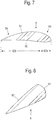
- the vanes are shaped so that their maximum thickness lies in a forward portion of the vanes, viewed in the direction of rotation of the hub.
- the wings are in accordance with a preferred embodiment, an airfoil-shaped, with a convex shaped top with substantially in the direction of rotation of the hub rearwardly decreasing curvature and a bottom, which merges continuously from a convex curved, in the direction of rotation of the hub portion in a concave curved rear portion ,
- the wing-like shape of the wings of such a mixing tool is advantageous in many respects.
- such a mixing tool can achieve good thorough mixing of the mix at a comparatively low running speed.
- Such wings can be positioned at a sufficiently large distance from the bottom of the mixer head, so that even for a cleaning of the mixing tool and the mixer disassembly of the mixing tool is not necessary, which is associated with a large time savings.
- the free ends of the wings each have an angle to the respective wing aligned outer wing.
- the turbulence of the mixed material is reduced during the rotation of the mixing tool, so that thereby a laminar flow is favored, with which the mixed material is mixed, which contributes to the avoidance of deposits on the mixing tool and the side wall of the mixer.
- the outer wings are preferably wedge-shaped, with a convex front surface.
- the outer wings are aligned obliquely tilted to the axis of rotation of the hub.
- the outer wings are preferably mounted at the free end of the wing. Also conceivable is a one-piece molding of the outer wing at the free end of the wing. Also preferably, the wings are mounted on the hub.
- the span of the blades of the mixing tool is dimensioned such that the distance of a radially outer edge of the wings from the side inner wall of the mixer head is between 5% and 60% of the wingspan.
- the distance between the underside of the wings from the bottom of the mixer head is between 1% and 35% of the wingspan.
- the transition between the bottom and the side inner wall is continuous according to a preferred embodiment, in particular formed as a circular peripheral portion, which provides for an additional buoyancy of the mixed material upon rotation of the mixing tool.
- the bottom can be formed as a flat, circular disk-shaped plate, which can be followed by a peripheral side wall as part of the mixer head can be placed on the mixing container.
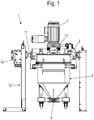
- Fig. 1 is designated by the reference numeral 1 a total of a mixer for powdered, semolina and / or granular substances.
- the mixer 1 in this case essentially has a mixing container 8, on which a mixer head 2 can be placed and with which the mixing container 8 can be closed.
- the mixing container 8 and the mixer head 2 are supported on a stand 12.
- an outlet 9 is provided, through which the ready mixed mix can be removed from the mixing container 8.
- a mixing tool 3 is arranged, which is rotatably supported by a drive 7 parallel to a bottom 21 of the mixer head 2 on a bottom 21 of the mixer head 2 passing through and driven by the drive 7 drive axle 10.
- a hub 4 of the mixing tool 3 is rotatably attached.
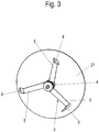
- the mixing tool 3 has three radially or approximately radially to one of the drive axle 10 of the drive 7 corresponding axis of rotation A projecting wings 5.
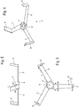
- the vanes 5 are shaped so that their maximum thickness d max in a viewed in the direction of rotation R of the hub 4, front portion 53 of the wings 5 is located. In a rear portion 54 of the wings, the thickness d of the wings slowly decreases.
- the wings 5 are preferably shaped wing-shaped.
- a wing-shaped a shape of the wings is called wing, in which a convex shaped top 51 with substantially in the direction of rotation D.
- the hub 4 is formed decreasing toward the rear curvature and in which a bottom 52 of the wings 5 of a convex curved, in the direction of rotation D of the hub 4 front portion 52a continuously merges into a concavely curved rear portion 52b.
- the wings 5 can be aligned tilted parallel or at an angle to a plane perpendicular to the axis of rotation A of the hub 4.
- the wings 5 are preferably oriented upward by 0 ° to 45 ° to the horizontal.
- the wings 5 are preferably flat. It is also conceivable, the wings 5 bent or kinked form. So it is conceivable, for example, that the wings 5 extend starting from the hub 4 initially aligned parallel or angularly tilted to a plane perpendicular to the axis of rotation A of the hub 4 and bend or bend in a remote from the hub 4 area up or down.
- the wings 5 are preferably aligned parallel and spaced from the bottom 21 of the mixer head 2 in the radial direction.
- the outer wings 6 are preferably wedge-shaped, with a convexly shaped front surface 61 which, viewed in the direction of rotation D of the hub 4 during the mixing process, tapers rearwardly to form a wedge-shaped region 62.
- the outer wings 6 are preferably aligned perpendicular to the longitudinal axis of the wings 5, wherein the convex shaped front surface 61 of the outer wings 6 are preferably tilted by 15 ° to 45 °, in particular by 20 °, tilted backwards from the vertical.
- the arranged on the hub 4 wings 5 are further preferably arranged at the same angular distance from each other.
- the outer wings 6 are preferably mounted at the free end of the wings 5.
- the wings 5 themselves are preferably mounted non-rotatably on the hub 4. It is conceivable in principle but also a one-piece design of the wings 5 with the hub. 4
- outer wings 6 are arranged at a distance from cylindrical side inner walls 22 of the mixer head 2.
- the mixer head 2 is in the in the Figures 2 and 3 embodiments shown pot-shaped, with a flat bottom 21 and a circumferentially adjoining the bottom 21 side inner wall 22nd
- the transition between the bottom 21 and the side inner wall 22 is continuous here, in particular formed as a circular peripheral portion.
- the span of the wings 5 is preferably dimensioned such that the distance between a radially outer edge of the wings 5 from the side inner wall 22 of the mixer head 2 is between 5% and 60% of the span I of the wings 5.
- the distance of the underside 52 of the wings 5 from the bottom 21 of the mixer head 2 is preferably between 1% and 35% of the span I of the wings 5, more preferably between 5% to 15%.
- the wing-shaped formation of the wings 5 also allows a sufficiently large distance between the wings 5 from the bottom 21 of the mixer head 2, to to carry out a cleaning without disassembly of the mixing tool 3 and at the same time to achieve a sufficiently large suction effect during rotation of the mixing tool 3 to thoroughly mix the mixing material to be mixed in the mixer 1, wherein the suction effect caused by the wing shape of the wings 5 at the same time to avoid of deposits on the bottom 21 of the mixer head 2 contributes.
- the bottom 21 of the mixer head 2 is disc-shaped, so that the mixing container 8 can be placed directly on this, so that in this case the circumferentially adjoining the bottom 21 side wall 22 as part of the mixer head 2 can be placed on the mixing container 8 is formed.
- the mixing tool 3 rotated by 180 ° to position a horizontal axis of rotation in the mixer head 2.
Landscapes
- Chemical & Material Sciences (AREA)
- Chemical Kinetics & Catalysis (AREA)
- Engineering & Computer Science (AREA)
- Aviation & Aerospace Engineering (AREA)
- Mixers Of The Rotary Stirring Type (AREA)
Applications Claiming Priority (1)
| Application Number | Priority Date | Filing Date | Title |
|---|---|---|---|
| DE202016107397.9U DE202016107397U1 (de) | 2016-12-27 | 2016-12-27 | Mischwerkzeug für einen Mischer und Mischer |
Publications (2)
| Publication Number | Publication Date |
|---|---|
| EP3342480A1 true EP3342480A1 (fr) | 2018-07-04 |
| EP3342480B1 EP3342480B1 (fr) | 2020-06-17 |
Family
ID=57868082
Family Applications (1)
| Application Number | Title | Priority Date | Filing Date |
|---|---|---|---|
| EP17152338.4A Active EP3342480B1 (fr) | 2016-12-27 | 2017-01-20 | Mélangeur avec outil de mélange |
Country Status (2)
| Country | Link |
|---|---|
| EP (1) | EP3342480B1 (fr) |
| DE (1) | DE202016107397U1 (fr) |
Cited By (2)
| Publication number | Priority date | Publication date | Assignee | Title |
|---|---|---|---|---|
| CN113276301A (zh) * | 2021-05-13 | 2021-08-20 | 江西蒂罗宝实业有限公司 | 一种石英石生产用自动混料装置 |
| DE102020129866A1 (de) | 2020-11-12 | 2022-05-12 | Zeppelin Systems Gmbh | Dichtungsvorrichtung |
Families Citing this family (1)
| Publication number | Priority date | Publication date | Assignee | Title |
|---|---|---|---|---|
| DE202019104870U1 (de) | 2019-09-04 | 2019-09-18 | Dr. Herfeld Gmbh & Co. Kg | Mischmaschine |
Citations (19)
| Publication number | Priority date | Publication date | Assignee | Title |
|---|---|---|---|---|
| US1981392A (en) * | 1932-12-03 | 1934-11-20 | Manganese Bronze & Brass Compa | Propeller and the like |
| DE1089368B (de) * | 1959-03-05 | 1960-09-22 | Kuehnle Kopp Kausch Ag | Umlaufender, mit Gasaustrittsoeffnungen versehener Feinstbegaser fuer faserstoffhaltige Fluessigkeiten |
| DE1278409B (de) * | 1965-10-11 | 1968-09-26 | Weinrich Heinrich Dr Ing | Vorrichtung zum Begasen von Fluessigkeiten |
| DE2135531A1 (en) * | 1970-07-17 | 1972-02-17 | Valmet Oy | Dissolving gas in liquid - esp oxygen in water using blades producing high and low pressures |
| US4135828A (en) * | 1977-11-25 | 1979-01-23 | Cabak James E | Mixing apparatus |
| US4571090A (en) * | 1984-04-11 | 1986-02-18 | General Signal Corp. | Mixing systems |
| EP0211279A2 (fr) * | 1985-07-30 | 1987-02-25 | General Signal Corporation | Appareil de mélange |
| DE8814068U1 (de) * | 1988-11-10 | 1989-01-05 | Dr. Herfeld GmbH & Co KG, 5982 Neuenrade | Mischvorrichtung |
| DE4005219A1 (de) * | 1990-02-20 | 1991-08-22 | Bohle L B Pharmatech Gmbh | Ruehrwerk fuer mischgranulatoren |
| US5158434A (en) * | 1990-07-26 | 1992-10-27 | General Signal Corporation | Mixing impellers and impeller systems for mixing and blending liquids and liquid suspensions having a wide range of viscosities |
| WO1994016804A1 (fr) * | 1993-01-21 | 1994-08-04 | General Signal Corporation | Palette d'agitation resistant a l'erosion |
| DE19848536A1 (de) * | 1998-10-21 | 2000-05-18 | Thyssen Henschel Gmbh | Mischer für pulver-, grieß- und/oder granulatförmige Stoffe |
| EP0963242B1 (fr) | 1997-02-28 | 2001-09-12 | Thyssen Henschel Gmbh | Melangeur pour poudres, granules et/ou autres substances granuleuses |
| US6331070B1 (en) * | 2000-10-30 | 2001-12-18 | Reliance Industries, Inc. | Process and apparatus for particle size reduction and homogeneous blending of ingredients in a fluidized change can mixer |
| US20060092762A1 (en) * | 2004-10-28 | 2006-05-04 | Xerox Corporation | High intensity blending tool with optimized risers for decreased toner agglomeration |
| EP1738862A1 (fr) * | 2005-06-30 | 2007-01-03 | SPX Corporation | Rotor mélangeur et procédé avec des éléments de sommet pré-formés. |
| EP2146092A2 (fr) * | 2008-07-17 | 2010-01-20 | Andreas Lehmkuhl | Eolienne |
| WO2012116883A1 (fr) * | 2011-02-28 | 2012-09-07 | Sulzer Mixpac Ag | Mélangeur dynamique |
| WO2014071993A1 (fr) * | 2012-11-09 | 2014-05-15 | Aktiebolaget Electrolux | Lame de mixeur et mixeur |
Family Cites Families (3)
| Publication number | Priority date | Publication date | Assignee | Title |
|---|---|---|---|---|
| US971409A (en) * | 1909-09-02 | 1910-09-27 | Theodore Roggenbuck | Propeller. |
| GB168586A (en) * | 1920-08-28 | 1922-02-23 | Krupp Ag | A new and improved means for securing on their shafts the stirring arms of stirring apparatus |
| US3397869A (en) * | 1967-05-03 | 1968-08-20 | Atomic Energy Commission Usa | Hydrofoil agitator blade |
-
2016
- 2016-12-27 DE DE202016107397.9U patent/DE202016107397U1/de active Active
-
2017
- 2017-01-20 EP EP17152338.4A patent/EP3342480B1/fr active Active
Patent Citations (20)
| Publication number | Priority date | Publication date | Assignee | Title |
|---|---|---|---|---|
| US1981392A (en) * | 1932-12-03 | 1934-11-20 | Manganese Bronze & Brass Compa | Propeller and the like |
| DE1089368B (de) * | 1959-03-05 | 1960-09-22 | Kuehnle Kopp Kausch Ag | Umlaufender, mit Gasaustrittsoeffnungen versehener Feinstbegaser fuer faserstoffhaltige Fluessigkeiten |
| DE1278409B (de) * | 1965-10-11 | 1968-09-26 | Weinrich Heinrich Dr Ing | Vorrichtung zum Begasen von Fluessigkeiten |
| DE2135531A1 (en) * | 1970-07-17 | 1972-02-17 | Valmet Oy | Dissolving gas in liquid - esp oxygen in water using blades producing high and low pressures |
| US4135828A (en) * | 1977-11-25 | 1979-01-23 | Cabak James E | Mixing apparatus |
| US4571090A (en) * | 1984-04-11 | 1986-02-18 | General Signal Corp. | Mixing systems |
| US4571090B1 (fr) * | 1984-04-11 | 1987-06-02 | ||
| EP0211279A2 (fr) * | 1985-07-30 | 1987-02-25 | General Signal Corporation | Appareil de mélange |
| DE8814068U1 (de) * | 1988-11-10 | 1989-01-05 | Dr. Herfeld GmbH & Co KG, 5982 Neuenrade | Mischvorrichtung |
| DE4005219A1 (de) * | 1990-02-20 | 1991-08-22 | Bohle L B Pharmatech Gmbh | Ruehrwerk fuer mischgranulatoren |
| US5158434A (en) * | 1990-07-26 | 1992-10-27 | General Signal Corporation | Mixing impellers and impeller systems for mixing and blending liquids and liquid suspensions having a wide range of viscosities |
| WO1994016804A1 (fr) * | 1993-01-21 | 1994-08-04 | General Signal Corporation | Palette d'agitation resistant a l'erosion |
| EP0963242B1 (fr) | 1997-02-28 | 2001-09-12 | Thyssen Henschel Gmbh | Melangeur pour poudres, granules et/ou autres substances granuleuses |
| DE19848536A1 (de) * | 1998-10-21 | 2000-05-18 | Thyssen Henschel Gmbh | Mischer für pulver-, grieß- und/oder granulatförmige Stoffe |
| US6331070B1 (en) * | 2000-10-30 | 2001-12-18 | Reliance Industries, Inc. | Process and apparatus for particle size reduction and homogeneous blending of ingredients in a fluidized change can mixer |
| US20060092762A1 (en) * | 2004-10-28 | 2006-05-04 | Xerox Corporation | High intensity blending tool with optimized risers for decreased toner agglomeration |
| EP1738862A1 (fr) * | 2005-06-30 | 2007-01-03 | SPX Corporation | Rotor mélangeur et procédé avec des éléments de sommet pré-formés. |
| EP2146092A2 (fr) * | 2008-07-17 | 2010-01-20 | Andreas Lehmkuhl | Eolienne |
| WO2012116883A1 (fr) * | 2011-02-28 | 2012-09-07 | Sulzer Mixpac Ag | Mélangeur dynamique |
| WO2014071993A1 (fr) * | 2012-11-09 | 2014-05-15 | Aktiebolaget Electrolux | Lame de mixeur et mixeur |
Cited By (3)
| Publication number | Priority date | Publication date | Assignee | Title |
|---|---|---|---|---|
| DE102020129866A1 (de) | 2020-11-12 | 2022-05-12 | Zeppelin Systems Gmbh | Dichtungsvorrichtung |
| EP4026610A1 (fr) | 2020-11-12 | 2022-07-13 | Zeppelin Systems GmbH | Dispositif d'étanchéité |
| CN113276301A (zh) * | 2021-05-13 | 2021-08-20 | 江西蒂罗宝实业有限公司 | 一种石英石生产用自动混料装置 |
Also Published As
| Publication number | Publication date |
|---|---|
| EP3342480B1 (fr) | 2020-06-17 |
| DE202016107397U1 (de) | 2018-03-28 |
Similar Documents
| Publication | Publication Date | Title |
|---|---|---|
| EP2937137B1 (fr) | Machine de mélange | |
| EP1631371B1 (fr) | Dispositif pour le traitement de solides | |
| EP3185732B1 (fr) | Ensemble couteau pour un appareil de cuisine et appareil de cuisine équipé d'un ensemble couteau | |
| DE102009018178A1 (de) | Scher-/Mischwerkzeug | |
| EP1639928B1 (fr) | Ensemble de lames pour un robot ménager a commande électromotrice et robot ménager correspondant | |
| EP3342480B1 (fr) | Mélangeur avec outil de mélange | |
| WO2015067745A1 (fr) | Moyen d'agitation pour fermenteur d'une installation de biogaz et procédé de fabrication d'un moyen d'agitation | |
| EP3789108B1 (fr) | Machine à mélanger industrielle | |
| EP1481721B1 (fr) | Mélangeur | |
| DE2147280B2 (de) | Vorrichtung zum Mischen von schüttbarem Erntegut | |
| DE2643560C2 (de) | Rührvorrichtung | |
| DE3515318A1 (de) | Stiftmuehle fuer mischer | |
| DE3013663C2 (de) | Mischarm | |
| EP0799593B1 (fr) | Outil de mixage pour un appareil de cuisine pour mélanger et mousser de la nourriture | |
| EP2321398B1 (fr) | Cuve à maische pour la fabrication de bière et malaxeur pour cuve à maische | |
| DE102013219061B3 (de) | Mischwerkzeug | |
| DE19504033C2 (de) | Flügelscheibe für Rührwellen | |
| EP2821143B1 (fr) | Mélangeur-couteau pour un hachoir | |
| DE202020100951U1 (de) | Mischer | |
| DE102013202876B3 (de) | Mischwerkzeug | |
| DE202007013977U1 (de) | Rührvorrichtung | |
| EP3883678B1 (fr) | Outil de mélange pour machine de mélange industrielle, ensemble d'outils de mélange comportant de tels outils de mélange et machine de mélange comportant un tel ensemble d'outils de mélange | |
| DE4005219C2 (fr) | ||
| EP0870705B1 (fr) | Conteneur pour le stockage et la distribution dosée de particules de bois telles que copeaux, éclats et sciure | |
| DE20219943U1 (de) | Vorrichtung zum Umwälzen von Flüssigmist und Abwasser in einem Vorratsbehälter |
Legal Events
| Date | Code | Title | Description |
|---|---|---|---|
| PUAI | Public reference made under article 153(3) epc to a published international application that has entered the european phase |
Free format text: ORIGINAL CODE: 0009012 |
|
| STAA | Information on the status of an ep patent application or granted ep patent |
Free format text: STATUS: THE APPLICATION HAS BEEN PUBLISHED |
|
| AK | Designated contracting states |
Kind code of ref document: A1 Designated state(s): AL AT BE BG CH CY CZ DE DK EE ES FI FR GB GR HR HU IE IS IT LI LT LU LV MC MK MT NL NO PL PT RO RS SE SI SK SM TR |
|
| AX | Request for extension of the european patent |
Extension state: BA ME |
|
| STAA | Information on the status of an ep patent application or granted ep patent |
Free format text: STATUS: REQUEST FOR EXAMINATION WAS MADE |
|
| 17P | Request for examination filed |
Effective date: 20181227 |
|
| RBV | Designated contracting states (corrected) |
Designated state(s): AL AT BE BG CH CY CZ DE DK EE ES FI FR GB GR HR HU IE IS IT LI LT LU LV MC MK MT NL NO PL PT RO RS SE SI SK SM TR |
|
| GRAP | Despatch of communication of intention to grant a patent |
Free format text: ORIGINAL CODE: EPIDOSNIGR1 |
|
| STAA | Information on the status of an ep patent application or granted ep patent |
Free format text: STATUS: GRANT OF PATENT IS INTENDED |
|
| INTG | Intention to grant announced |
Effective date: 20200326 |
|
| GRAS | Grant fee paid |
Free format text: ORIGINAL CODE: EPIDOSNIGR3 |
|
| GRAA | (expected) grant |
Free format text: ORIGINAL CODE: 0009210 |
|
| STAA | Information on the status of an ep patent application or granted ep patent |
Free format text: STATUS: THE PATENT HAS BEEN GRANTED |
|
| AK | Designated contracting states |
Kind code of ref document: B1 Designated state(s): AL AT BE BG CH CY CZ DE DK EE ES FI FR GB GR HR HU IE IS IT LI LT LU LV MC MK MT NL NO PL PT RO RS SE SI SK SM TR |
|
| REG | Reference to a national code |
Ref country code: GB Ref legal event code: FG4D Free format text: NOT ENGLISH |
|
| REG | Reference to a national code |
Ref country code: CH Ref legal event code: EP |
|
| REG | Reference to a national code |
Ref country code: DE Ref legal event code: R096 Ref document number: 502017005690 Country of ref document: DE |
|
| REG | Reference to a national code |
Ref country code: IE Ref legal event code: FG4D Free format text: LANGUAGE OF EP DOCUMENT: GERMAN |
|
| REG | Reference to a national code |
Ref country code: AT Ref legal event code: REF Ref document number: 1280631 Country of ref document: AT Kind code of ref document: T Effective date: 20200715 |
|
| PG25 | Lapsed in a contracting state [announced via postgrant information from national office to epo] |
Ref country code: FI Free format text: LAPSE BECAUSE OF FAILURE TO SUBMIT A TRANSLATION OF THE DESCRIPTION OR TO PAY THE FEE WITHIN THE PRESCRIBED TIME-LIMIT Effective date: 20200617 Ref country code: SE Free format text: LAPSE BECAUSE OF FAILURE TO SUBMIT A TRANSLATION OF THE DESCRIPTION OR TO PAY THE FEE WITHIN THE PRESCRIBED TIME-LIMIT Effective date: 20200617 Ref country code: LT Free format text: LAPSE BECAUSE OF FAILURE TO SUBMIT A TRANSLATION OF THE DESCRIPTION OR TO PAY THE FEE WITHIN THE PRESCRIBED TIME-LIMIT Effective date: 20200617 Ref country code: GR Free format text: LAPSE BECAUSE OF FAILURE TO SUBMIT A TRANSLATION OF THE DESCRIPTION OR TO PAY THE FEE WITHIN THE PRESCRIBED TIME-LIMIT Effective date: 20200918 Ref country code: NO Free format text: LAPSE BECAUSE OF FAILURE TO SUBMIT A TRANSLATION OF THE DESCRIPTION OR TO PAY THE FEE WITHIN THE PRESCRIBED TIME-LIMIT Effective date: 20200917 |
|
| REG | Reference to a national code |
Ref country code: LT Ref legal event code: MG4D |
|
| REG | Reference to a national code |
Ref country code: NL Ref legal event code: MP Effective date: 20200617 |
|
| PG25 | Lapsed in a contracting state [announced via postgrant information from national office to epo] |
Ref country code: RS Free format text: LAPSE BECAUSE OF FAILURE TO SUBMIT A TRANSLATION OF THE DESCRIPTION OR TO PAY THE FEE WITHIN THE PRESCRIBED TIME-LIMIT Effective date: 20200617 Ref country code: LV Free format text: LAPSE BECAUSE OF FAILURE TO SUBMIT A TRANSLATION OF THE DESCRIPTION OR TO PAY THE FEE WITHIN THE PRESCRIBED TIME-LIMIT Effective date: 20200617 Ref country code: HR Free format text: LAPSE BECAUSE OF FAILURE TO SUBMIT A TRANSLATION OF THE DESCRIPTION OR TO PAY THE FEE WITHIN THE PRESCRIBED TIME-LIMIT Effective date: 20200617 Ref country code: BG Free format text: LAPSE BECAUSE OF FAILURE TO SUBMIT A TRANSLATION OF THE DESCRIPTION OR TO PAY THE FEE WITHIN THE PRESCRIBED TIME-LIMIT Effective date: 20200917 |
|
| PG25 | Lapsed in a contracting state [announced via postgrant information from national office to epo] |
Ref country code: NL Free format text: LAPSE BECAUSE OF FAILURE TO SUBMIT A TRANSLATION OF THE DESCRIPTION OR TO PAY THE FEE WITHIN THE PRESCRIBED TIME-LIMIT Effective date: 20200617 Ref country code: AL Free format text: LAPSE BECAUSE OF FAILURE TO SUBMIT A TRANSLATION OF THE DESCRIPTION OR TO PAY THE FEE WITHIN THE PRESCRIBED TIME-LIMIT Effective date: 20200617 |
|
| PG25 | Lapsed in a contracting state [announced via postgrant information from national office to epo] |
Ref country code: SM Free format text: LAPSE BECAUSE OF FAILURE TO SUBMIT A TRANSLATION OF THE DESCRIPTION OR TO PAY THE FEE WITHIN THE PRESCRIBED TIME-LIMIT Effective date: 20200617 Ref country code: EE Free format text: LAPSE BECAUSE OF FAILURE TO SUBMIT A TRANSLATION OF THE DESCRIPTION OR TO PAY THE FEE WITHIN THE PRESCRIBED TIME-LIMIT Effective date: 20200617 Ref country code: RO Free format text: LAPSE BECAUSE OF FAILURE TO SUBMIT A TRANSLATION OF THE DESCRIPTION OR TO PAY THE FEE WITHIN THE PRESCRIBED TIME-LIMIT Effective date: 20200617 Ref country code: CZ Free format text: LAPSE BECAUSE OF FAILURE TO SUBMIT A TRANSLATION OF THE DESCRIPTION OR TO PAY THE FEE WITHIN THE PRESCRIBED TIME-LIMIT Effective date: 20200617 Ref country code: PT Free format text: LAPSE BECAUSE OF FAILURE TO SUBMIT A TRANSLATION OF THE DESCRIPTION OR TO PAY THE FEE WITHIN THE PRESCRIBED TIME-LIMIT Effective date: 20201019 Ref country code: ES Free format text: LAPSE BECAUSE OF FAILURE TO SUBMIT A TRANSLATION OF THE DESCRIPTION OR TO PAY THE FEE WITHIN THE PRESCRIBED TIME-LIMIT Effective date: 20200617 |
|
| PG25 | Lapsed in a contracting state [announced via postgrant information from national office to epo] |
Ref country code: IS Free format text: LAPSE BECAUSE OF FAILURE TO SUBMIT A TRANSLATION OF THE DESCRIPTION OR TO PAY THE FEE WITHIN THE PRESCRIBED TIME-LIMIT Effective date: 20201017 Ref country code: SK Free format text: LAPSE BECAUSE OF FAILURE TO SUBMIT A TRANSLATION OF THE DESCRIPTION OR TO PAY THE FEE WITHIN THE PRESCRIBED TIME-LIMIT Effective date: 20200617 Ref country code: PL Free format text: LAPSE BECAUSE OF FAILURE TO SUBMIT A TRANSLATION OF THE DESCRIPTION OR TO PAY THE FEE WITHIN THE PRESCRIBED TIME-LIMIT Effective date: 20200617 |
|
| REG | Reference to a national code |
Ref country code: DE Ref legal event code: R097 Ref document number: 502017005690 Country of ref document: DE |
|
| PLBE | No opposition filed within time limit |
Free format text: ORIGINAL CODE: 0009261 |
|
| STAA | Information on the status of an ep patent application or granted ep patent |
Free format text: STATUS: NO OPPOSITION FILED WITHIN TIME LIMIT |
|
| PG25 | Lapsed in a contracting state [announced via postgrant information from national office to epo] |
Ref country code: DK Free format text: LAPSE BECAUSE OF FAILURE TO SUBMIT A TRANSLATION OF THE DESCRIPTION OR TO PAY THE FEE WITHIN THE PRESCRIBED TIME-LIMIT Effective date: 20200617 |
|
| 26N | No opposition filed |
Effective date: 20210318 |
|
| PG25 | Lapsed in a contracting state [announced via postgrant information from national office to epo] |
Ref country code: SI Free format text: LAPSE BECAUSE OF FAILURE TO SUBMIT A TRANSLATION OF THE DESCRIPTION OR TO PAY THE FEE WITHIN THE PRESCRIBED TIME-LIMIT Effective date: 20200617 |
|
| PG25 | Lapsed in a contracting state [announced via postgrant information from national office to epo] |
Ref country code: MC Free format text: LAPSE BECAUSE OF FAILURE TO SUBMIT A TRANSLATION OF THE DESCRIPTION OR TO PAY THE FEE WITHIN THE PRESCRIBED TIME-LIMIT Effective date: 20200617 |
|
| REG | Reference to a national code |
Ref country code: CH Ref legal event code: PL |
|
| GBPC | Gb: european patent ceased through non-payment of renewal fee |
Effective date: 20210120 |
|
| PG25 | Lapsed in a contracting state [announced via postgrant information from national office to epo] |
Ref country code: LU Free format text: LAPSE BECAUSE OF NON-PAYMENT OF DUE FEES Effective date: 20210120 |
|
| REG | Reference to a national code |
Ref country code: BE Ref legal event code: MM Effective date: 20210131 |
|
| PG25 | Lapsed in a contracting state [announced via postgrant information from national office to epo] |
Ref country code: FR Free format text: LAPSE BECAUSE OF NON-PAYMENT OF DUE FEES Effective date: 20210131 |
|
| REG | Reference to a national code |
Ref country code: DE Ref legal event code: R079 Ref document number: 502017005690 Country of ref document: DE Free format text: PREVIOUS MAIN CLASS: B01F0013000000 Ipc: B01F0033000000 |
|
| PG25 | Lapsed in a contracting state [announced via postgrant information from national office to epo] |
Ref country code: CH Free format text: LAPSE BECAUSE OF NON-PAYMENT OF DUE FEES Effective date: 20210131 Ref country code: LI Free format text: LAPSE BECAUSE OF NON-PAYMENT OF DUE FEES Effective date: 20210131 Ref country code: GB Free format text: LAPSE BECAUSE OF NON-PAYMENT OF DUE FEES Effective date: 20210120 |
|
| PG25 | Lapsed in a contracting state [announced via postgrant information from national office to epo] |
Ref country code: IE Free format text: LAPSE BECAUSE OF NON-PAYMENT OF DUE FEES Effective date: 20210120 |
|
| PG25 | Lapsed in a contracting state [announced via postgrant information from national office to epo] |
Ref country code: IS Free format text: LAPSE BECAUSE OF FAILURE TO SUBMIT A TRANSLATION OF THE DESCRIPTION OR TO PAY THE FEE WITHIN THE PRESCRIBED TIME-LIMIT Effective date: 20201017 |
|
| PG25 | Lapsed in a contracting state [announced via postgrant information from national office to epo] |
Ref country code: BE Free format text: LAPSE BECAUSE OF NON-PAYMENT OF DUE FEES Effective date: 20210131 |
|
| PG25 | Lapsed in a contracting state [announced via postgrant information from national office to epo] |
Ref country code: CY Free format text: LAPSE BECAUSE OF FAILURE TO SUBMIT A TRANSLATION OF THE DESCRIPTION OR TO PAY THE FEE WITHIN THE PRESCRIBED TIME-LIMIT Effective date: 20200617 |
|
| PG25 | Lapsed in a contracting state [announced via postgrant information from national office to epo] |
Ref country code: HU Free format text: LAPSE BECAUSE OF FAILURE TO SUBMIT A TRANSLATION OF THE DESCRIPTION OR TO PAY THE FEE WITHIN THE PRESCRIBED TIME-LIMIT; INVALID AB INITIO Effective date: 20170120 |
|
| PGFP | Annual fee paid to national office [announced via postgrant information from national office to epo] |
Ref country code: AT Payment date: 20240105 Year of fee payment: 8 |
|
| PG25 | Lapsed in a contracting state [announced via postgrant information from national office to epo] |
Ref country code: MK Free format text: LAPSE BECAUSE OF FAILURE TO SUBMIT A TRANSLATION OF THE DESCRIPTION OR TO PAY THE FEE WITHIN THE PRESCRIBED TIME-LIMIT Effective date: 20200617 |
|
| PGFP | Annual fee paid to national office [announced via postgrant information from national office to epo] |
Ref country code: DE Payment date: 20240301 Year of fee payment: 8 |
|
| PGFP | Annual fee paid to national office [announced via postgrant information from national office to epo] |
Ref country code: IT Payment date: 20240131 Year of fee payment: 8 |