EP3341671B1 - Wärmeaustauschvorrichtung zur energierückgewinnung aus verbrennungsdämpfen - Google Patents
Wärmeaustauschvorrichtung zur energierückgewinnung aus verbrennungsdämpfen Download PDFInfo
- Publication number
- EP3341671B1 EP3341671B1 EP16798272.7A EP16798272A EP3341671B1 EP 3341671 B1 EP3341671 B1 EP 3341671B1 EP 16798272 A EP16798272 A EP 16798272A EP 3341671 B1 EP3341671 B1 EP 3341671B1
- Authority
- EP
- European Patent Office
- Prior art keywords
- plates
- fumes
- heat exchange
- box
- outlet
- Prior art date
- Legal status (The legal status is an assumption and is not a legal conclusion. Google has not performed a legal analysis and makes no representation as to the accuracy of the status listed.)
- Active
Links
Images


Classifications
-
- F—MECHANICAL ENGINEERING; LIGHTING; HEATING; WEAPONS; BLASTING
- F28—HEAT EXCHANGE IN GENERAL
- F28F—DETAILS OF HEAT-EXCHANGE AND HEAT-TRANSFER APPARATUS, OF GENERAL APPLICATION
- F28F3/00—Plate-like or laminated elements; Assemblies of plate-like or laminated elements
- F28F3/12—Elements constructed in the shape of a hollow panel, e.g. with channels
- F28F3/14—Elements constructed in the shape of a hollow panel, e.g. with channels by separating portions of a pair of joined sheets to form channels, e.g. by inflation
-
- F—MECHANICAL ENGINEERING; LIGHTING; HEATING; WEAPONS; BLASTING
- F28—HEAT EXCHANGE IN GENERAL
- F28D—HEAT-EXCHANGE APPARATUS, NOT PROVIDED FOR IN ANOTHER SUBCLASS, IN WHICH THE HEAT-EXCHANGE MEDIA DO NOT COME INTO DIRECT CONTACT
- F28D21/00—Heat-exchange apparatus not covered by any of the groups F28D1/00 - F28D20/00
- F28D21/0001—Recuperative heat exchangers
- F28D21/0003—Recuperative heat exchangers the heat being recuperated from exhaust gases
-
- F—MECHANICAL ENGINEERING; LIGHTING; HEATING; WEAPONS; BLASTING
- F28—HEAT EXCHANGE IN GENERAL
- F28F—DETAILS OF HEAT-EXCHANGE AND HEAT-TRANSFER APPARATUS, OF GENERAL APPLICATION
- F28F27/00—Control arrangements or safety devices specially adapted for heat-exchange or heat-transfer apparatus
- F28F27/02—Control arrangements or safety devices specially adapted for heat-exchange or heat-transfer apparatus for controlling the distribution of heat-exchange media between different channels
Definitions
- the present invention relates to a heat exchange device for energy recovery (heat) from combustion fumes and more generally from fluids in the gaseous state having an adequate temperature.
- the present invention relates to a heat exchange device for fumes coming from boilers, steam generators, industrial ovens (and, more generally, from processes in which an effluent in the gaseous state is available for heat exchange) and allows recovery of a part of the heat associated with said fumes which, passing through said device, transfer heat to a second fluid (heat transfer fluid or secondary fluid) which may be in the liquid state and/or two-phase state (liquid and vapor).
- a second fluid heat transfer fluid or secondary fluid
- the transfer of heat from the fumes to the secondary fluid allows the temperature to be increased and, at the same time, the temperature of the fumes to be lowered before they are emitted into the atmosphere.
- heat exchange devices of this type are installed between a boiler and the relative flue and, more generally, on a chimney, and they are able to intercept a part of the energy associated with the gaseous effluent, recover it and reuse it.
- Patent document WO2015004591 describes an apparatus of this type comprising a parallelepiped body having an inlet for the fumes on a face of the parallelepiped, which inside comprises a horizontal heat exchanger and a device for purification of the fumes connected in cascade with each other and an outlet connected to a flue, positioned on the opposite face of the parallelepiped.
- the heat exchanger comprises a plurality of plates, each with a surface with a substantially rectangular shape oriented in the same direction as the fumes.
- Each plate is obtained by two sheets joined together by welding and then subjected to bulging according to a known technique for obtaining channels designed for the passage of the heat transfer fluid; the plurality of plates, enclosed in the parallelepiped body, is lapped externally by the passage of the fumes, thereby creating the heat exchange between the two spaces.
- the heat exchanger of the above-mentioned patent document WO2015004591 has an inlet duct for the heat transfer fluid located on a surface of the parallelepiped and an outlet duct for the fluid located on the opposite surface of the parallelepiped.
- This apparatus is modular in the sense that several parallelepiped bodies may be placed alongside each other.
- the apparatus is constrained to a single positioning, wherein the inlet and outlet of the fumes are located on opposite faces of the same parallelepiped allowing an exclusively linear path for the fumes also due to the presence of the module for purification of the fumes located in cascade with the heat exchanger; the heat transfer fluid is introduced on one face and extracted from the opposite face of the parallelepiped.
- the aim of this invention is to overcome the above-mentioned limitations by proposing a heat exchanger device which is modular and versatile in its installation, in which the inlet and outlet of the fumes can be positioned in various ways.
- An aspect of the present invention concerns a heat exchange device for fumes (gaseous) having the characteristics of the accompanying claim 1.
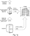
- the device according to the present invention comprises at least one heat exchange module 2 including a plurality of plates 3 each formed by two joined sheets, for example by welding and bulged in order to form inner channels 34 designed for the passage of the heat transfer fluid.
- This module 2 has at least one inlet duct 4 and one outlet duct 5 for the fluid, connected to the channels 34 of the plates through the tubes 35-36.
- the plurality of plates, enclosed in the parallelepiped body, is lapped externally by the passage of the fumes, thereby creating the heat exchange between the two spaces.
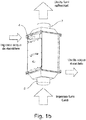
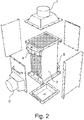
- the device is formed by a box-shaped body, in which is inserted the module, having at least one inlet opening for the fumes 6, 6', 8', which can be operated selectively, located on one of the four faces perpendicular to the plane of parallelism of the plates and at least one outlet opening for the fumes which can also be operated selectively 7 or 7' positioned on any one of the remaining faces in such a way as to form predetermined paths for the fumes inside the module.
- the box-shaped body comprises openable partitions which facilitate the cleaning and inspection operations of the module comprising the plates.
- the inlet opening in some embodiments may be single.
- it can be double, positioned on opposite faces, between the four faces perpendicular to the plane of parallelism of the plates, whilst the single outlet 7 can be positioned on one of the two remaining faces in such a way as to form paths of the fumes which can be selected inside the module.
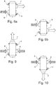
- Figures 3a to 6b , 9 and 10 illustrate nine embodiments of the invention.
- Figure 3a shows an L-shaped path in which the inlet opening 6' is on a vertical side of the box-shaped body and the outlet opening 7 of the fumes is positioned on the top of the box-shaped body.
- the path is an L-shaped path in which the inlet opening 6' is on a vertical side of the box-shaped body but the outlet opening 7 of the fumes is positioned on the bottom of the box-shaped body.
- a path which is visible in Figure 5a is a vertical rectilinear path, in which the inlet and outlet openings of the fumes are positioned on the lower and upper base of the box-shaped body.
- a further path which can be seen in Figures 6a and 6b is a Z-shaped path in which the inlet opening 6' is on a vertical side of the box-shaped body and the outlet opening 7' of the fumes is positioned on the opposite vertical side of the box-shaped body.
- the path of the fumes shown in Figures 9 and 10 is T-shaped with the two inlet openings on the opposite vertical sides 6' and 8' and the outlet opening 7 is positioned on the top ( Figure 9 ) or on the lower base of the box-shaped body ( Figure 10 ).
- the device according to the present invention is modular in the sense that several devices can be positioned both in cascade and parallel to each other. Moreover, several embodiments can be combined together to allow systems to be constructed which can be positioned in spaces that are sometimes even restricted.
- Each plate 3 is made using a pair of sheets 31 and 32 joined together by junction points 33 and closure of the flaps along the edges of the sheets (for example by welding), and subsequent mechanical, pneumatic or hydraulic deformation to distance the two sheets at the points not joined (welded) in order to form spaces/channels 34 inside the plate for the passage of the heat transfer fluid.
- Each plate also comprises at least one tube 35 for introduction of the fluid and at least one tube 36 for extraction of the fluid, preferably positioned close to opposite corners of the plate.
- the plates 33 are in construction terms all identical to each other and as such geometrically congruent, they are assembled in the plurality 3 parallel to each other but, at the same time, asymmetrically, so that each of them is rotated by 180° relative to the axis perpendicular to the plane of parallelism of the plates, with respect to the contiguous plate(s).
- the purpose of this parallel-asymmetric configuration of the plates is to increase the turbulence of the gaseous fluid which passes through the device, with the convex parts of a plate being located in correspondence with concave parts of the contiguous plates ( Figure 8b and 8c ).
- the inlet 35 and outlet 36 tubes of the thermal vector are positioned at different distances (x and y) from the edges (of the plate) contiguous and parallel to the respective tubes 35 and 36, so that following the rotated positioning of two contiguous plates, the same connection tubes are staggered ( Figure 8d ) on the duct allowing the plates to be positioned at a close distance: that is, only in this way can the spacing between two contiguous plates be less than the diameter of the tubes 35 and 36.
- the side by side arrangement of two adjacent plates is such as to make the "bulging" parts of the channels 34 of a plate correspond with the "recessed” parts of the adjacent plates at the junction points 33 ( Figure 8c ).
- the positioning of the tubes 35 or 36 for connection of the plates to the input 4 (or output 5) ducts of the heat exchanger is achieved by means of a bracket 9 which has the purpose of compensating for the various thermal expansions to which the plurality of plates 3 are subjected, which are colder because they are crossed by the heat transfer fluid, and the box-shaped body which is at a higher temperature because it is crossed by the hot fumes.
- the bracket is "omega" shaped with the two arms 91, 92 constrained to the box-shaped body, whilst the tubes 35 or 36 are inserted in openings 93 made in the central part of the bracket. The central portion of the omega is then connected with the hydraulic inlet 4 or outlet 5 duct.
- the bracket 9 therefore allows a minimum distance z to be maintained between the edges of the plurality of plates 3 and the box-shaped body, thereby giving a greater compactness and efficiency of the heat exchange, but simultaneously guaranteeing a greater length z' of the tubes 35 and 36 designed for the absorption of the various thermal expansions between the plates and the box-shaped body.
- the versatility and the modularity of the device according to the present invention allows a fuel saving of up to 15%, compared with the 3-5% of the most common applications. In fact, it transforms the traditional boilers, even the oldest ones, into condensing boilers, recovering also the latent heat of condensation as well as the sensible heat. Moreover, the device according to the present invention neither slows down or obstructs in any way the normal transit of the fumes towards the flue thanks to the smooth geometry of the plates and the absence of roughness.
- this geometry determines a turbulence of the fumes such as to allow a high heat transfer. Thanks to the heat exchange efficiency, the device has smaller dimensions than known devices, which therefore allows the installation even in restricted spaces.
- the maintenance is simplified, fast and economic thanks to the partitions which can be easily removed which make the plates completely accessible. This cleaning is possible without having to dismantle the unit from the system or disassembling the plates.
Landscapes
- Engineering & Computer Science (AREA)
- Physics & Mathematics (AREA)
- Thermal Sciences (AREA)
- Mechanical Engineering (AREA)
- General Engineering & Computer Science (AREA)
- Heat-Exchange Devices With Radiators And Conduit Assemblies (AREA)
Claims (10)
- Wärmeaustauschvorrichtung zum Übertragen von Wärme von Fluiden im gasförmigen Zustand auf Fluide im flüssigen und/oder Dampfzustand und das mindestens ein Wärmetauschermodul (2), einschließlich einer Vielzahl von übereinandergelagerten Platten (3), von denen jede aus zwei Blechen (31,32) besteht, die an Verbindungspunkten (33) miteinander verbunden sind, und die deformiert sind, um Kanäle (34), die ausgelegt sind, ein Wärmetauscherfluid zu enthalten, und Pfade für die Strömung der Dämpfe außerhalb der Platten in thermischem Kontakt miteinander zu erhalten, wobei ein solches Modul mindestens einen Einlasskanal (4) und einen Auslasskanal (5) für das Wärmetauscherfluid, einen kastenförmigen Körper aufweist, in den ein solches Modul eingeführt ist, der mindestens eine Einlassöffnung (6, 6', 8') und mindestens eine Auslassöffnung (7, 7') umfasst,
wobei» die Platten (3) nebeneinander in einer versetzten Anordnung positioniert und in der Vielzahl parallel zueinander, jedoch asymmetrisch angeordnet sind, so dass jede davon, bezogen auf die Achse, die normal zur Parallelismus-Ebene zwischen den Platten selbst steht, in Hinblick auf die benachbarte Platte, um 180° gedreht ist,
wobei die Anordnung von zwei benachbarten Platten (3) nebeneinander so ausgeführt ist, dass die hervortretenden Teile der Kanäle (34) einer Platte (3) in die vertieften Teile der benachbarten Platten (3) an den Verbindungspunkten (33) passen, so dass der Raum zwischen zwei Platten, der den Dampfpfad darstellt, ein wellenförmiger Pfad ist,» jede Platte mindestens ein Zufuhrrohr (35) für das Fluid und mindestens ein Gewinnungsrohr (36) für das Fluid selbst umfasst, die in der Nähe von gegenüberliegenden Ecken der Platte positioniert sind, dadurch gekennzeichnet, dass
sich die mindestens eine Einlassöffnung (6, 6', 8') auf einer der vier Flächen, normal zur Parallelismus-Ebene der Platten (3), befindet und sich die mindestens eine Auslassöffnung (7, 7') auf mindestens einer der übrigen Flächen befindet, wobei sowohl die Einlassöffnung (6, 6', 8') als auch die Auslassöffnung (7, 7') selektiv betätigbar sind,» die Verbindung der Rohre (35, 36) zum Verbinden der Platten mit dem Einlass- und dem Auslasskanal (4, 5) des Tauschers insgesamt mittels einer im Wesentlichen Omega-förmigen Klammer (9) mit zwei Armen (91, 92) erhalten wird, die an dem kastenförmigen Körper fixiert sind, während die Rohre (35 oder 36) in Öffnungen (93), die im Mittelteil der Klammer selbst erhalten werden, eingeführt sind. - Wärmeaustauschvorrichtung nach Anspruch 1, wobei die Einlassöffnung eine Doppelöffnung(6', 8') ist, die auf gegenüberliegenden Flächen der vier Flächen, normal zur Parallelismus-Ebene der Platten, positioniert ist, während der Auslass eine Einzelöffnung (7) ist und auf einer der beiden übrigen Flächen positioniert werden kann.
- Wärmeaustauschvorrichtung nach Anspruch 2, wobei der Pfad der Dämpfe eine "T"-Form aufweist, wobei sich die zwei Einlassöffnungen auf gegenüberliegenden vertikalen Seiten (6' und 8') befinden und der Auslass (7) auf dem kastenförmigen Körper positioniert ist.
- Wärmeaustauschvorrichtung nach Anspruch 2, wobei der Pfad der Dämpfe eine "T"-Form aufweist, wobei sich die zwei Einlassöffnungen auf gegenüberliegenden vertikalen Seiten (6' und 8') befinden und der Auslass (7) auf der unteren Basis des kastenförmigen Körpers positioniert ist.
- Wärmeaustauschvorrichtung nach Anspruch 1, wobei ein Pfad der Dämpfe vertikal geradlinig ist, in dem die Einlass- (6) und die Auslass- (7) Öffnungen der Dämpfe auf einer unteren und oberen Basis des kastenförmigen Körpers positioniert sind.
- Wärmeaustauschvorrichtung nach Anspruch 1, wobei der Pfad der Dämpfe eine "L"-Form aufweist, in der sich die Einlassöffnung (6') auf einer vertikalen Seite des kastenförmigen Körpers befindet und die Auslassöffnung (7) für die Dämpfe auf dem kastenförmigen Körper positioniert ist.
- Wärmeaustauschvorrichtung nach Anspruch 1, wobei der Pfad der Dämpfe eine "Z"-Form aufweist, in der sich die Einlassöffnung (6') auf einer vertikalen Seite des kastenförmigen Körpers befindet und die Auslassöffnung (7) der Dämpfe auf der gegenüberliegenden vertikalen Seite des kastenförmigen Körpers positioniert ist.
- Wärmeaustauschvorrichtung nach Anspruch 1, wobei das Einlass- (35) und das Auslass- (36) Rohr des thermischen Vektors in unterschiedlichen Abständen (x und y) von den Rändern der Platte positioniert sind, so dass dieselben Verbindungsrohre gemäß der gedrehten Positionierung zweier benachbarter Platten versetzt auf dem Kollektor angeordnet sind.
- Wärmeaustauschvorrichtung nach Anspruch 8, wobei der Abstand zwischen zwei benachbarten Platten kleiner sein kann als der Durchmesser der Rohre (35 und 36).
- Wärmeaustauschvorrichtung nach Anspruch 1, wobei ein solcher kastenförmiger Körper öffnungsfähige Abtrennungen umfasst, die Reinigungs- und Prüfvorgänge des die Platten umfassenden Moduls erleichtern.
Priority Applications (1)
| Application Number | Priority Date | Filing Date | Title |
|---|---|---|---|
| PL16798272T PL3341671T3 (pl) | 2015-09-28 | 2016-09-28 | Urządzenie do wymiany ciepła służące do odzyskiwania energii ze spalin |
Applications Claiming Priority (2)
| Application Number | Priority Date | Filing Date | Title |
|---|---|---|---|
| ITUB2015A003951A ITUB20153951A1 (it) | 2015-09-28 | 2015-09-28 | Dispositivo di scambio termico per il recupero energetico da fumi di combustione. |
| PCT/IB2016/055802 WO2017056017A1 (en) | 2015-09-28 | 2016-09-28 | Heat exchange device for energy recovery from combustion fumes |
Publications (2)
| Publication Number | Publication Date |
|---|---|
| EP3341671A1 EP3341671A1 (de) | 2018-07-04 |
| EP3341671B1 true EP3341671B1 (de) | 2019-11-13 |
Family
ID=55237707
Family Applications (1)
| Application Number | Title | Priority Date | Filing Date |
|---|---|---|---|
| EP16798272.7A Active EP3341671B1 (de) | 2015-09-28 | 2016-09-28 | Wärmeaustauschvorrichtung zur energierückgewinnung aus verbrennungsdämpfen |
Country Status (5)
| Country | Link |
|---|---|
| EP (1) | EP3341671B1 (de) |
| ES (1) | ES2773981T3 (de) |
| IT (1) | ITUB20153951A1 (de) |
| PL (1) | PL3341671T3 (de) |
| WO (1) | WO2017056017A1 (de) |
Family Cites Families (4)
| Publication number | Priority date | Publication date | Assignee | Title |
|---|---|---|---|---|
| DE4333904C2 (de) * | 1993-09-27 | 1996-02-22 | Eberhard Dipl Ing Paul | Kanalwärmetauscher |
| IT1401963B1 (it) * | 2010-09-23 | 2013-08-28 | Tenova Spa | Scambiatore di calore per il raffreddamento rapido di fumi di impianti siderurgici, apparato di trattamento di fumi di impianti siderurgici comprendente tale scambiatore di calore e relativo metodo di trattamento. |
| WO2014176676A1 (en) * | 2013-04-29 | 2014-11-06 | Gerald Landry | Energy recovery system and method |
| ITMI20131152A1 (it) * | 2013-07-09 | 2015-01-10 | Thermo Recovery S R L | Apparato per il recupero del calore con modulo di depurazione fumi. |
-
2015
- 2015-09-28 IT ITUB2015A003951A patent/ITUB20153951A1/it unknown
-
2016
- 2016-09-28 WO PCT/IB2016/055802 patent/WO2017056017A1/en not_active Ceased
- 2016-09-28 ES ES16798272T patent/ES2773981T3/es active Active
- 2016-09-28 PL PL16798272T patent/PL3341671T3/pl unknown
- 2016-09-28 EP EP16798272.7A patent/EP3341671B1/de active Active
Non-Patent Citations (1)
| Title |
|---|
| None * |
Also Published As
| Publication number | Publication date |
|---|---|
| ITUB20153951A1 (it) | 2017-03-28 |
| PL3341671T3 (pl) | 2020-11-02 |
| WO2017056017A1 (en) | 2017-04-06 |
| ES2773981T3 (es) | 2020-07-16 |
| EP3341671A1 (de) | 2018-07-04 |
Similar Documents
| Publication | Publication Date | Title |
|---|---|---|
| JP2007192535A (ja) | 熱交換器装置 | |
| JP2017194261A (ja) | 熱交換器 | |
| JP5182570B2 (ja) | 給湯装置 | |
| US20090178779A1 (en) | Heat exchanger | |
| EP3341671B1 (de) | Wärmeaustauschvorrichtung zur energierückgewinnung aus verbrennungsdämpfen | |
| US10247444B2 (en) | Furnace and method for heating air | |
| CN102419122A (zh) | 两相流空气预热器 | |
| CN210180243U (zh) | 一种可拆式烟气换热器 | |
| KR100993035B1 (ko) | 열교환기용 주름관 및 그를 포함한 열교환기 | |
| CN102080935A (zh) | 一种工业废气的余热回收装置 | |
| JP2017072342A (ja) | 排熱回収ボイラ及び排熱回収ボイラのガスシール方法 | |
| KR102210094B1 (ko) | 콘덴싱 보일러용 열교환기 | |
| EP2707670A2 (de) | Wärmetauscher | |
| GB2049126A (en) | Boiler | |
| CN203203440U (zh) | 板式空气预热器 | |
| JP2014190577A (ja) | 排熱ボイラユニット及び排熱ボイラ | |
| US3364992A (en) | Plate type heat-exchangers having corrugated, zig-zag sheet members | |
| CN105737136A (zh) | 一种u形管过热器 | |
| RU202092U1 (ru) | Водонагревательный котёл | |
| US20250052506A1 (en) | Plate heat exhanger arrangement, use of it in exhaust gas heat recovery and method for recovering heat from exhaust gas | |
| RU126814U1 (ru) | Пластинчатый теплообменник | |
| CN202304515U (zh) | 两相流空气预热器 | |
| JP2025014424A (ja) | 熱交換装置 | |
| KR20240079685A (ko) | 전열관 유닛 및 이를 포함하는 폐열회수보일러 | |
| CN205191631U (zh) | 一种燃气化铁炉的叠加式可拆卸管状换热元件 |
Legal Events
| Date | Code | Title | Description |
|---|---|---|---|
| STAA | Information on the status of an ep patent application or granted ep patent |
Free format text: STATUS: UNKNOWN |
|
| STAA | Information on the status of an ep patent application or granted ep patent |
Free format text: STATUS: THE INTERNATIONAL PUBLICATION HAS BEEN MADE |
|
| PUAI | Public reference made under article 153(3) epc to a published international application that has entered the european phase |
Free format text: ORIGINAL CODE: 0009012 |
|
| STAA | Information on the status of an ep patent application or granted ep patent |
Free format text: STATUS: REQUEST FOR EXAMINATION WAS MADE |
|
| 17P | Request for examination filed |
Effective date: 20180327 |
|
| AK | Designated contracting states |
Kind code of ref document: A1 Designated state(s): AL AT BE BG CH CY CZ DE DK EE ES FI FR GB GR HR HU IE IS IT LI LT LU LV MC MK MT NL NO PL PT RO RS SE SI SK SM TR |
|
| AX | Request for extension of the european patent |
Extension state: BA ME |
|
| DAV | Request for validation of the european patent (deleted) | ||
| DAX | Request for extension of the european patent (deleted) | ||
| GRAP | Despatch of communication of intention to grant a patent |
Free format text: ORIGINAL CODE: EPIDOSNIGR1 |
|
| STAA | Information on the status of an ep patent application or granted ep patent |
Free format text: STATUS: GRANT OF PATENT IS INTENDED |
|
| INTG | Intention to grant announced |
Effective date: 20190605 |
|
| GRAS | Grant fee paid |
Free format text: ORIGINAL CODE: EPIDOSNIGR3 |
|
| GRAA | (expected) grant |
Free format text: ORIGINAL CODE: 0009210 |
|
| STAA | Information on the status of an ep patent application or granted ep patent |
Free format text: STATUS: THE PATENT HAS BEEN GRANTED |
|
| AK | Designated contracting states |
Kind code of ref document: B1 Designated state(s): AL AT BE BG CH CY CZ DE DK EE ES FI FR GB GR HR HU IE IS IT LI LT LU LV MC MK MT NL NO PL PT RO RS SE SI SK SM TR |
|
| REG | Reference to a national code |
Ref country code: CH Ref legal event code: EP Ref country code: AT Ref legal event code: REF Ref document number: 1202114 Country of ref document: AT Kind code of ref document: T Effective date: 20191115 |
|
| REG | Reference to a national code |
Ref country code: DE Ref legal event code: R096 Ref document number: 602016024403 Country of ref document: DE |
|
| REG | Reference to a national code |
Ref country code: IE Ref legal event code: FG4D |
|
| REG | Reference to a national code |
Ref country code: NL Ref legal event code: MP Effective date: 20191113 |
|
| REG | Reference to a national code |
Ref country code: LT Ref legal event code: MG4D |
|
| REG | Reference to a national code |
Ref country code: CH Ref legal event code: NV Representative=s name: VALIPAT S.A. C/O BOVARD SA NEUCHATEL, CH |
|
| PG25 | Lapsed in a contracting state [announced via postgrant information from national office to epo] |
Ref country code: NO Free format text: LAPSE BECAUSE OF FAILURE TO SUBMIT A TRANSLATION OF THE DESCRIPTION OR TO PAY THE FEE WITHIN THE PRESCRIBED TIME-LIMIT Effective date: 20200213 Ref country code: GR Free format text: LAPSE BECAUSE OF FAILURE TO SUBMIT A TRANSLATION OF THE DESCRIPTION OR TO PAY THE FEE WITHIN THE PRESCRIBED TIME-LIMIT Effective date: 20200214 Ref country code: NL Free format text: LAPSE BECAUSE OF FAILURE TO SUBMIT A TRANSLATION OF THE DESCRIPTION OR TO PAY THE FEE WITHIN THE PRESCRIBED TIME-LIMIT Effective date: 20191113 Ref country code: LT Free format text: LAPSE BECAUSE OF FAILURE TO SUBMIT A TRANSLATION OF THE DESCRIPTION OR TO PAY THE FEE WITHIN THE PRESCRIBED TIME-LIMIT Effective date: 20191113 Ref country code: LV Free format text: LAPSE BECAUSE OF FAILURE TO SUBMIT A TRANSLATION OF THE DESCRIPTION OR TO PAY THE FEE WITHIN THE PRESCRIBED TIME-LIMIT Effective date: 20191113 Ref country code: SE Free format text: LAPSE BECAUSE OF FAILURE TO SUBMIT A TRANSLATION OF THE DESCRIPTION OR TO PAY THE FEE WITHIN THE PRESCRIBED TIME-LIMIT Effective date: 20191113 Ref country code: PT Free format text: LAPSE BECAUSE OF FAILURE TO SUBMIT A TRANSLATION OF THE DESCRIPTION OR TO PAY THE FEE WITHIN THE PRESCRIBED TIME-LIMIT Effective date: 20200313 Ref country code: FI Free format text: LAPSE BECAUSE OF FAILURE TO SUBMIT A TRANSLATION OF THE DESCRIPTION OR TO PAY THE FEE WITHIN THE PRESCRIBED TIME-LIMIT Effective date: 20191113 Ref country code: BG Free format text: LAPSE BECAUSE OF FAILURE TO SUBMIT A TRANSLATION OF THE DESCRIPTION OR TO PAY THE FEE WITHIN THE PRESCRIBED TIME-LIMIT Effective date: 20200213 |
|
| PG25 | Lapsed in a contracting state [announced via postgrant information from national office to epo] |
Ref country code: HR Free format text: LAPSE BECAUSE OF FAILURE TO SUBMIT A TRANSLATION OF THE DESCRIPTION OR TO PAY THE FEE WITHIN THE PRESCRIBED TIME-LIMIT Effective date: 20191113 Ref country code: RS Free format text: LAPSE BECAUSE OF FAILURE TO SUBMIT A TRANSLATION OF THE DESCRIPTION OR TO PAY THE FEE WITHIN THE PRESCRIBED TIME-LIMIT Effective date: 20191113 Ref country code: IS Free format text: LAPSE BECAUSE OF FAILURE TO SUBMIT A TRANSLATION OF THE DESCRIPTION OR TO PAY THE FEE WITHIN THE PRESCRIBED TIME-LIMIT Effective date: 20200313 |
|
| PG25 | Lapsed in a contracting state [announced via postgrant information from national office to epo] |
Ref country code: AL Free format text: LAPSE BECAUSE OF FAILURE TO SUBMIT A TRANSLATION OF THE DESCRIPTION OR TO PAY THE FEE WITHIN THE PRESCRIBED TIME-LIMIT Effective date: 20191113 |
|
| REG | Reference to a national code |
Ref country code: ES Ref legal event code: FG2A Ref document number: 2773981 Country of ref document: ES Kind code of ref document: T3 Effective date: 20200716 |
|
| PG25 | Lapsed in a contracting state [announced via postgrant information from national office to epo] |
Ref country code: DK Free format text: LAPSE BECAUSE OF FAILURE TO SUBMIT A TRANSLATION OF THE DESCRIPTION OR TO PAY THE FEE WITHIN THE PRESCRIBED TIME-LIMIT Effective date: 20191113 Ref country code: EE Free format text: LAPSE BECAUSE OF FAILURE TO SUBMIT A TRANSLATION OF THE DESCRIPTION OR TO PAY THE FEE WITHIN THE PRESCRIBED TIME-LIMIT Effective date: 20191113 Ref country code: CZ Free format text: LAPSE BECAUSE OF FAILURE TO SUBMIT A TRANSLATION OF THE DESCRIPTION OR TO PAY THE FEE WITHIN THE PRESCRIBED TIME-LIMIT Effective date: 20191113 Ref country code: RO Free format text: LAPSE BECAUSE OF FAILURE TO SUBMIT A TRANSLATION OF THE DESCRIPTION OR TO PAY THE FEE WITHIN THE PRESCRIBED TIME-LIMIT Effective date: 20191113 |
|
| REG | Reference to a national code |
Ref country code: DE Ref legal event code: R097 Ref document number: 602016024403 Country of ref document: DE |
|
| REG | Reference to a national code |
Ref country code: AT Ref legal event code: MK05 Ref document number: 1202114 Country of ref document: AT Kind code of ref document: T Effective date: 20191113 |
|
| PG25 | Lapsed in a contracting state [announced via postgrant information from national office to epo] |
Ref country code: SK Free format text: LAPSE BECAUSE OF FAILURE TO SUBMIT A TRANSLATION OF THE DESCRIPTION OR TO PAY THE FEE WITHIN THE PRESCRIBED TIME-LIMIT Effective date: 20191113 Ref country code: SM Free format text: LAPSE BECAUSE OF FAILURE TO SUBMIT A TRANSLATION OF THE DESCRIPTION OR TO PAY THE FEE WITHIN THE PRESCRIBED TIME-LIMIT Effective date: 20191113 |
|
| PLBE | No opposition filed within time limit |
Free format text: ORIGINAL CODE: 0009261 |
|
| STAA | Information on the status of an ep patent application or granted ep patent |
Free format text: STATUS: NO OPPOSITION FILED WITHIN TIME LIMIT |
|
| 26N | No opposition filed |
Effective date: 20200814 |
|
| PG25 | Lapsed in a contracting state [announced via postgrant information from national office to epo] |
Ref country code: SI Free format text: LAPSE BECAUSE OF FAILURE TO SUBMIT A TRANSLATION OF THE DESCRIPTION OR TO PAY THE FEE WITHIN THE PRESCRIBED TIME-LIMIT Effective date: 20191113 Ref country code: AT Free format text: LAPSE BECAUSE OF FAILURE TO SUBMIT A TRANSLATION OF THE DESCRIPTION OR TO PAY THE FEE WITHIN THE PRESCRIBED TIME-LIMIT Effective date: 20191113 |
|
| REG | Reference to a national code |
Ref country code: BE Ref legal event code: MM Effective date: 20200930 |
|
| PG25 | Lapsed in a contracting state [announced via postgrant information from national office to epo] |
Ref country code: LU Free format text: LAPSE BECAUSE OF NON-PAYMENT OF DUE FEES Effective date: 20200928 |
|
| PG25 | Lapsed in a contracting state [announced via postgrant information from national office to epo] |
Ref country code: BE Free format text: LAPSE BECAUSE OF NON-PAYMENT OF DUE FEES Effective date: 20200930 Ref country code: IE Free format text: LAPSE BECAUSE OF NON-PAYMENT OF DUE FEES Effective date: 20200928 |
|
| PG25 | Lapsed in a contracting state [announced via postgrant information from national office to epo] |
Ref country code: TR Free format text: LAPSE BECAUSE OF FAILURE TO SUBMIT A TRANSLATION OF THE DESCRIPTION OR TO PAY THE FEE WITHIN THE PRESCRIBED TIME-LIMIT Effective date: 20191113 Ref country code: MT Free format text: LAPSE BECAUSE OF FAILURE TO SUBMIT A TRANSLATION OF THE DESCRIPTION OR TO PAY THE FEE WITHIN THE PRESCRIBED TIME-LIMIT Effective date: 20191113 Ref country code: CY Free format text: LAPSE BECAUSE OF FAILURE TO SUBMIT A TRANSLATION OF THE DESCRIPTION OR TO PAY THE FEE WITHIN THE PRESCRIBED TIME-LIMIT Effective date: 20191113 |
|
| PG25 | Lapsed in a contracting state [announced via postgrant information from national office to epo] |
Ref country code: MK Free format text: LAPSE BECAUSE OF FAILURE TO SUBMIT A TRANSLATION OF THE DESCRIPTION OR TO PAY THE FEE WITHIN THE PRESCRIBED TIME-LIMIT Effective date: 20191113 Ref country code: MC Free format text: LAPSE BECAUSE OF FAILURE TO SUBMIT A TRANSLATION OF THE DESCRIPTION OR TO PAY THE FEE WITHIN THE PRESCRIBED TIME-LIMIT Effective date: 20191113 |
|
| PGFP | Annual fee paid to national office [announced via postgrant information from national office to epo] |
Ref country code: DE Payment date: 20240806 Year of fee payment: 9 |
|
| PGFP | Annual fee paid to national office [announced via postgrant information from national office to epo] |
Ref country code: GB Payment date: 20240808 Year of fee payment: 9 |
|
| PGFP | Annual fee paid to national office [announced via postgrant information from national office to epo] |
Ref country code: FR Payment date: 20240808 Year of fee payment: 9 |
|
| PGFP | Annual fee paid to national office [announced via postgrant information from national office to epo] |
Ref country code: PL Payment date: 20240716 Year of fee payment: 9 |
|
| PGFP | Annual fee paid to national office [announced via postgrant information from national office to epo] |
Ref country code: ES Payment date: 20241007 Year of fee payment: 9 |
|
| PGFP | Annual fee paid to national office [announced via postgrant information from national office to epo] |
Ref country code: CH Payment date: 20241001 Year of fee payment: 9 |
|
| PGFP | Annual fee paid to national office [announced via postgrant information from national office to epo] |
Ref country code: IT Payment date: 20250922 Year of fee payment: 10 |