EP3341145B1 - Schwimmende klemmringanordnung - Google Patents
Schwimmende klemmringanordnung Download PDFInfo
- Publication number
- EP3341145B1 EP3341145B1 EP16842982.7A EP16842982A EP3341145B1 EP 3341145 B1 EP3341145 B1 EP 3341145B1 EP 16842982 A EP16842982 A EP 16842982A EP 3341145 B1 EP3341145 B1 EP 3341145B1
- Authority
- EP
- European Patent Office
- Prior art keywords
- clamp ring
- ring assembly
- multiseal
- assembly
- dome die
- Prior art date
- Legal status (The legal status is an assumption and is not a legal conclusion. Google has not performed a legal analysis and makes no representation as to the accuracy of the status listed.)
- Active
Links
- 230000002093 peripheral effect Effects 0.000 claims 3
- 229920001973 fluoroelastomer Polymers 0.000 claims 2
- 239000000463 material Substances 0.000 description 14
- 230000000712 assembly Effects 0.000 description 8
- 238000000429 assembly Methods 0.000 description 8
- 238000004519 manufacturing process Methods 0.000 description 8
- 239000004696 Poly ether ether ketone Substances 0.000 description 2
- 235000013361 beverage Nutrition 0.000 description 2
- 235000012489 doughnuts Nutrition 0.000 description 2
- 235000013305 food Nutrition 0.000 description 2
- 238000000034 method Methods 0.000 description 2
- 229920002530 polyetherether ketone Polymers 0.000 description 2
- 238000007665 sagging Methods 0.000 description 2
- 229910000831 Steel Inorganic materials 0.000 description 1
- 229910052782 aluminium Inorganic materials 0.000 description 1
- XAGFODPZIPBFFR-UHFFFAOYSA-N aluminium Chemical compound [Al] XAGFODPZIPBFFR-UHFFFAOYSA-N 0.000 description 1
- 125000004122 cyclic group Chemical group 0.000 description 1
- 230000001351 cycling effect Effects 0.000 description 1
- 230000007547 defect Effects 0.000 description 1
- 230000013011 mating Effects 0.000 description 1
- 229910052751 metal Inorganic materials 0.000 description 1
- 239000002184 metal Substances 0.000 description 1
- 239000000203 mixture Substances 0.000 description 1
- 230000000284 resting effect Effects 0.000 description 1
- 239000010959 steel Substances 0.000 description 1
- 229920001169 thermoplastic Polymers 0.000 description 1
- 239000004416 thermosoftening plastic Substances 0.000 description 1
- 230000037303 wrinkles Effects 0.000 description 1
Images


Classifications
-
- B—PERFORMING OPERATIONS; TRANSPORTING
- B21—MECHANICAL METAL-WORKING WITHOUT ESSENTIALLY REMOVING MATERIAL; PUNCHING METAL
- B21D—WORKING OR PROCESSING OF SHEET METAL OR METAL TUBES, RODS OR PROFILES WITHOUT ESSENTIALLY REMOVING MATERIAL; PUNCHING METAL
- B21D22/00—Shaping without cutting, by stamping, spinning, or deep-drawing
- B21D22/20—Deep-drawing
- B21D22/30—Deep-drawing to finish articles formed by deep-drawing
-
- B—PERFORMING OPERATIONS; TRANSPORTING
- B21—MECHANICAL METAL-WORKING WITHOUT ESSENTIALLY REMOVING MATERIAL; PUNCHING METAL
- B21D—WORKING OR PROCESSING OF SHEET METAL OR METAL TUBES, RODS OR PROFILES WITHOUT ESSENTIALLY REMOVING MATERIAL; PUNCHING METAL
- B21D22/00—Shaping without cutting, by stamping, spinning, or deep-drawing
- B21D22/20—Deep-drawing
- B21D22/28—Deep-drawing of cylindrical articles using consecutive dies
-
- B—PERFORMING OPERATIONS; TRANSPORTING
- B21—MECHANICAL METAL-WORKING WITHOUT ESSENTIALLY REMOVING MATERIAL; PUNCHING METAL
- B21D—WORKING OR PROCESSING OF SHEET METAL OR METAL TUBES, RODS OR PROFILES WITHOUT ESSENTIALLY REMOVING MATERIAL; PUNCHING METAL
- B21D51/00—Making hollow objects
- B21D51/16—Making hollow objects characterised by the use of the objects
- B21D51/26—Making hollow objects characterised by the use of the objects cans or tins; Closing same in a permanent manner
Definitions
- the present assembly relates generally to assemblies used in the manufacture of metal containers. Particularly, the assembly relates to a clamp ring retainer assembly for use in a bottom forming assembly used in the drawing and forming of the bottom portions of two piece steel and aluminum cans.
- a clamp ring assembly which floats a clamp ring to respond to variations in bodymaker punch locations is disclosed.
- the clamp ring assembly is comprised of an arrangement of components to improve the centering and biasing control of the clamp ring and the inner dome die or dome plug.
- the clamp ring retainer is provided to house a floating clamp ring.
- a biasing assembly comprised of a multifaceted shaped compressible member or multiseal member and a cooperating slide ring are provided in a circumferential channel of the clamp ring for biasing or floating the clamp ring within a can bottom forming assembly.
- the multiseal or formed compressible member has a cross-sectional configuration winch provides stable positioning of the slide ring and the multiseal member within the circumferential channel of the clamp ring.
- An improved dome plug or inner dome die is provided having a tapered side wall that allows clearance between the clamp ring and the dome die when the clamp ring is in its resting position and which aids to center the clamp ring when it is engaged by the
- Exemplary embodiments can improve manufacturing parameters by providing a more evenly distributed clamping force to control material flow as it is formed into the can bottom geometry when there is variation in the alignment of the punch with respect to the bottom former.
- Exemplary embodiments can also provide a larger operating window with respect to punch/bottom former alignment while producing a can meeting desired specifications.
- Exemplary embodiments can also provide spatial control of the clamp ring along and normal to the axis of ram movement to thereby provide for greater can manufacturing quality. production and efficiency.
- a clamp ring assembly may be utilized in can bottom forming assemblies, for example, as disclosed in U.S. Pat. No. 4,936,330 ('330 Patent), entitled Double Action Bottom Former, U.S. Pat. No. 6,490,904 B1 ('904 Patent), entitled Double Action Bottom Former for High Cyclic Operation, U.S. Pat. No. 7,290,428 B2 ('428 Patent), entitled Can Bottom Forming Assembly and in U.S. Pat. No. 7526,937 B2 ('937 Patent), entitled Can Bottom Forming Assembly, all owned via assignment by Applicant.
- the bottom former assemblies of the '330, '904, '428 and '937 Patents are constructed and arranged for cooperating use with a can bodymaker and specifically, the bodymaker punch carrying the can bodies.
- the '330, '904, '428 and '937 Patents disclose dome plug positioning structures for can bottom forming assemblies.
- the '330, '904, '428 and '937 Patents describe can bottom forming processes including the action of the punch or ram of a can bodymaker assembly with respect to a bottom forming assembly.
- Bottom forming assemblies are typically constructed and arranged to cooperate with bodymaker assemblies.
- the bottom former receives can bodies on the rapid cycling bodymaker punch and forms two piece can body bottoms through a drawing and final forming process utilizing a clamp ring and dome plug.
- clamp ring is also known in the industry as a pressure ring, guide ring or outer die.
- dome plug is also known in the industry as an inner dome die or dome post
- the specific manufacture of cans, beverage or food, may determine the use of the particular term.
- the walls of the can body are formed in a bodymaker assembly, the operation of which is described in the '330, '904, '428 and '937 Patents.
- a punch i.e. from the bodymaker structure, carries the can body out of the tool pack to the clamp ring of the bottom forming assembly.
- the clamp ring is constructed and arranged to float to thereby guide the punch to the center of the doming assembly and to re-center upon the exit of the punch. As the punch travels into the bottom forming assembly, the clamp ring structure axially centers the punch with the dome plug.
- the clamp ring When making two piece beverage cans, the clamp ring is used as a draw ring to apply pressure on the can material as it flows into the dome, thus controlling the material flow and preventing defects such as wrinkles.
- the clamp ring acts as a guide member to align grooves in the punch with mating grooves in the inner die or dome plug.
- the exemplary clamp ring assembly provides a more evenly distributed clamping force to control material flow as it is formed into the can bottom geometry when there is misalignment of the bottom former relative to the punch. Specifically, it provides a biasing assembly for the floating clamp ring that provides a higher initial resistive force than prior art clamp rings in order to reduce sagging of the clamp ring which could result in misalignment. Further, the configuration and combination of elements in the biasing assembly provides an increased life and reduced failure of the biasing assembly materials. Further, the configuration of the inner dome die or dome plug further aids in the spatial control of the clamp ring and ram. The clamp ring assembly and improved dome plug can thereby provide a larger operating window with respect to punch/bottom former alignment while producing a can meeting desired specifications.
- the clamp ring assembly may be used in a bottom forming assembly which provides a floating clamp ring to center the ram or punch of a bodymaker and an inner dome die to accommodate greater ram or punch misalignment.
- the clamp ring assembly 10 is shown and described with respect to Figures 1-4a and is shown in use in a bottom forming assembly in Figure 5 .
- the clamp ring assembly 10 is comprised of an arrangement of components to improve the centering and biasing control of the clamp ring 11.
- the clamp ring retainer 12 is shown to house a floating clamp ring 11.
- a floating or biasing assembly 14 comprising a multifaceted compressible shaped member or multi seal member 15 and a cooperating slide ring 16 is provided for biasing or floating the clamp ring 11 within a can bottom forming assembly, the latter being disclosed, for example, in the above referenced '330, '904, '428 and '937 Patents of Applicant.
- An inner dome die 13 is provided having a configuration to center the clamp ring 11 and to thereby further accommodate punch or ram misalignment.
- circumferential channel 17 is shown in clamp ring 11 and which is constructed and arranged to house biasing or floating assembly 14 which is shown comprised of slide ring 16 and cooperating multiseal member 15 which is seated within a circumferential slot of the slide ring 16.
- Slide ring 16 is made of a wear resistant material intended to provide a longer life than the O-ring interface material.
- the slide ring 16 may be constructed of a polyether ether ketone thermoplastic (PEEK) or a like low-wear material.
- Multiseal member 15 is preferably constructed of a flexible compressible material and is constructed and arranged to compress radially.
- the multiseal member 15 may be constructed of a fluoroelaslomeric or like polymeric material. The latter material compositions may be formulated to function in high temperature conditions.
- the multifaceted shaped member or multiseal member 15 is shown having a multi-faceted cross sectional configuration, and is shown seated within the circumferential channel 17 of the clamp ring 11. By being able to compress radially, multiseal member 15 provides flexibility to allow contact from a misaligned punch to move the clamp ring 11 in a direction that improves its axial alignment with the punch and corresponding can body.
- multiseal member 15 is shown in Figure 4 and is utilized with the cooperating slide ring 16, as opposed to an O-ring as it increases the life of the material and prevents spiral failure of the material. Further multiseal member 15 provides greater surface area contact with slide ring 16 thereby providing a higher initial resistive force to reduce sagging of the clamp ring 11, which may result in misalignment.
- the multiseal member 15 is shown in cross-section to have generally flat opposing end portions 30 and 31 and a pair of outwardly extending ridge members 32 and 33 therebetween.
- the configuration of the multiseal member 15 provides a stable positioning of the multifaceted shaped multiseal member 15 within the circumferential channel 17 of the clamp ring 11.
- the combination of the multiseal member 15 and the slide ring 16 preferably has a height whereby the dome plug 13 is aligned when the multiseal member 15 is not in a compressed state and the slide ring 16 touches the wall of the clamp ring retainer 12.
- the cross sectional configuration of the multiseal member 15 shows the ability of the multifaceted shaped ring member to be stable in position when in the compressed and noncompressed state.
- the outwardly or axially extending ridge members 32 and 33 provide stability and allow the top, bottom and mid portions of multiseal member 15 to bulge outwardly when radially compressed, thereby providing for the integrity of the multifaceted shaped ring member structure 15.
- inner dome die 13 is shown having a tapered side wall 18 that allows clearance between clamp ring 11 and dome die 13 when the clamp ring is in its fully extended position prior to the punch, with can body, making contact.
- the clearance is equal to the amount of float designed into the slide ring interface.
- the tapered side wall 18 may be disposed at an angle of approximately 91° with respect to flange 19 of inner dome die 13, with a preferred angle range of approximately 90.5-91.5°, or at an angle range of approximately 0.5-1.5° from the horizontal clamp ring inner wall as shown in Figure 3 .
- Tapered side wall 18 is designed to center clamp ring 11 progressively as the punch, with can body, moves the clamp ring until it is seated against flange 19 of dome die 13. The latter ensures that the final form of the can bottom has the features created by clamp ring 11 concentric with those created by dome die 13.
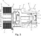
- FIG. 5 shows the clamp ring retainer assembly 10 in use in a can bottom forming assembly 20.
- Clamp ring retainer 12, clamp ring 11 and dome die 13 are shown positioned within lock nut 27 at one end of assembly 20.
- Floating or biasing cooperating assembly 14 is shown positioned within channel 17 of clamp ring 11.
- Inner dome die 13 is shown having flange 19 and tapered side wall 18.
- Can bottom forming assembly 20 generally comprises a cylinder housing 21 forming axial chambers and housing piston 25.
- Cover plate 22 is shown adjacent cylinder housing 21 and donut spring 23.
- Spring end plate 24 is shown positioned adjacent the donut spring 23 and at the opposite end of assembly 20 as the floating clamp ring assembly 10.
- Outer housing 26 and mounting flange 28 are shown for mounting bottom forming assembly 20 with respect to can bodymaking equipment.
- Clamp ring retainer assembly 10 can provide a more even clamping force to control material flow as it is formed into the can bottom geometry when there is misalignment of the punch with respect to the bottom former.
- the assembly 10 facilitates a larger operating window regarding punch/bottom former alignment, while producing a can meeting desired specifications.
Landscapes
- Engineering & Computer Science (AREA)
- Mechanical Engineering (AREA)
- Shaping Metal By Deep-Drawing, Or The Like (AREA)
- Containers Having Bodies Formed In One Piece (AREA)
- Moulds For Moulding Plastics Or The Like (AREA)
- Sealing Devices (AREA)
Claims (12)
- Klemmringanordnung zur Verwendung in einem Dosenbodenformer, wobei die Klemmringanordnung folgendes aufweist:einen Klemmringhalter,einen Klemmring, der einen umlaufenden Kanal und zusammenwirkende Vorspannelemente, die in dem umlaufenden Kanal gelagert sind, besitzt; und eine innere Kuppelmatrize, die einen Flansch besitzt, unddie dadurch gekennzeichnet ist, dass sie eine angeschrägte Seitenwand aufweist.
- Klemmringanordnung gemäß Anspruch 1, wobei die zusammenwirkenden Vorspannelemente des Klemmrings einen Gleitring und ein Mehrfachdichtungselement aufweisen.
- Klemmringanordnung gemäß Anspruch 1, wobei die angeschrägte Seitenwand der inneren Kugelmatrize in einem Winkelbereich von 90,5 bis 91,5° in bezug auf den Flansch angeordnet ist, um dadurch eine leicht konische Form der inneren Kuppelmatrize zu bilden.
- Klemmringanordnung gemäß Anspruch 2, wobei das Mehrfachdichtungselement eine mehrfachfacettierte Querschnittskonfiguration besitzt.
- Klemmringanordnung gemäß Anspruch 4, wobei das Mehrfachdichtungselement aus einem Fluoro-Elastomer aufgebaut ist.
- Klemmringanordnung gemäß Anspruch 2, wobei das Mehrfachdichtungselement deutlich kompressibel in mindestens einer radialen Richtung ist.
- Klemmringanordnung gemäß Anspruch 2, wobei das Mehrfachdichtungselement mindestens zwei im wesentlichen flache einander gegenüberliegende Endabschnitte und mindestens zwei sich axial erstreckende Grat-Elemente aufweist.
- Klemmringanordnung gemäß Anspruch 7, wobei das Mehrfachdichtungselement einen umfangsseitigen Grat besitzt und aus einem Fluoro-Elastomer aufgebaut ist.
- Klemmringanordnung gemäß Anspruch 2, wobei die inneren Kuppelmatrize eine angeschrägte Seitenwand besitzt, um hierdurch einen Freiraum zwischen dem Klemmring und der Kuppelmatrize vorzusehen, wenn der Klemmring sich in einer erstreckten Position befindet.
- Klemmringanordnung gemäß Anspruch 9, wobei die die innere Kuppelmatrize einen Flansch besitzt, und wobei die angeschrägte Seitenwand der inneren Kugelmatrize in einem Winkelbereich von 90,5 bis 91,5° in bezug auf den Flansch angeordnet ist, um dadurch eine leicht konische Form der inneren Kuppelmatrize zu bilden.
- Klemmringanordnung gemäß Anspruch 7, wobei das Mehrfachdichtungselement zwei Endabschnitte und einen Mittelabschnitt und ein Paar beabstandeter umfangsseitiger Grate besitzt, welche den Mittelabschnitt definieren, und wobei die umfangsseitigen Grate in berührender Beziehung in dem umlaufenden Kanal des Klemmrings sind, wenn in unkomprimiertem Zustand, und wobei der Mittelabschnitt aufgebaut und angeordnet ist, sich auswärts zum umlaufenden Kanal hin auszubeulen, wenn in komprimiertem Zustand.
- Klemmringanordnung gemäß Anspruch 10, wobei die angeschrägte Seitenwand der inneren Kugelmatrize in einem Winkel von ungefähr 91 ° in bezug auf den Flansch angeordnet ist.
Applications Claiming Priority (2)
| Application Number | Priority Date | Filing Date | Title |
|---|---|---|---|
| US201562213408P | 2015-09-02 | 2015-09-02 | |
| PCT/US2016/049895 WO2017040780A1 (en) | 2015-09-02 | 2016-09-01 | Floating clamp ring assembly |
Publications (3)
| Publication Number | Publication Date |
|---|---|
| EP3341145A1 EP3341145A1 (de) | 2018-07-04 |
| EP3341145A4 EP3341145A4 (de) | 2019-07-24 |
| EP3341145B1 true EP3341145B1 (de) | 2020-11-11 |
Family
ID=58188334
Family Applications (1)
| Application Number | Title | Priority Date | Filing Date |
|---|---|---|---|
| EP16842982.7A Active EP3341145B1 (de) | 2015-09-02 | 2016-09-01 | Schwimmende klemmringanordnung |
Country Status (7)
| Country | Link |
|---|---|
| US (1) | US10532390B2 (de) |
| EP (1) | EP3341145B1 (de) |
| JP (1) | JP6817293B2 (de) |
| CN (1) | CN107921506B (de) |
| BR (1) | BR112018004036B1 (de) |
| ES (1) | ES2843257T3 (de) |
| WO (1) | WO2017040780A1 (de) |
Families Citing this family (1)
| Publication number | Priority date | Publication date | Assignee | Title |
|---|---|---|---|---|
| GB2561859B (en) * | 2017-04-25 | 2019-04-24 | Crown Packaging Technology Inc | Can base forming |
Family Cites Families (16)
| Publication number | Priority date | Publication date | Assignee | Title |
|---|---|---|---|---|
| US4503702A (en) * | 1983-05-05 | 1985-03-12 | Redicon Corporation | Tapered container and method and apparatus for forming same |
| JPS6132860U (ja) * | 1984-07-31 | 1986-02-27 | 三菱電線工業株式会社 | キヤツプシ−ル |
| JPH026600A (ja) * | 1988-06-24 | 1990-01-10 | Nikka Chem Co Ltd | 水溶性の塑性加工用潤滑剤 |
| US5272902A (en) | 1990-09-06 | 1993-12-28 | Preferred Machining Corporation | Domer assembly for metal containers with nitrogen pressure source |
| US5797292A (en) | 1996-05-01 | 1998-08-25 | Coors Brewing Company | Domer apparatus for a can body making apparatus |
| GB9609407D0 (en) * | 1996-05-04 | 1996-07-10 | Metal Box Plc | Base forming station |
| JPH1095368A (ja) * | 1996-09-20 | 1998-04-14 | Suzuki Motor Corp | 自動車の前部車体構造及びその製作方法 |
| GB9719549D0 (en) * | 1997-09-16 | 1997-11-19 | Metal Box Plc | Base forming |
| GB9726009D0 (en) * | 1997-12-10 | 1998-02-04 | Metal Box Plc | Can base reforming |
| JP2001082606A (ja) * | 1999-09-10 | 2001-03-30 | Ckd Corp | 低摩擦流体圧アクチュエータ |
| US6490904B1 (en) | 2001-05-15 | 2002-12-10 | Mark L. Zauhar | Double action bottom former for high cyclic operation |
| EP1846179B1 (de) * | 2005-02-02 | 2011-10-12 | Mark L. Zauhar | Anordnung zur formung einer dosenunterseite |
| US7526937B2 (en) | 2006-02-02 | 2009-05-05 | Zauhar Mark L | Can bottom forming assembly |
| DE102010000235B4 (de) * | 2010-01-27 | 2012-01-26 | Schuler Pressen Gmbh & Co. Kg | Tiefziehwerkzeug zur Formung von Behälterböden |
| US8713980B2 (en) | 2011-05-31 | 2014-05-06 | Stolle Machinery Company, Llc | Automatic domer positioning in a bodymaker |
| US9550222B2 (en) * | 2012-09-21 | 2017-01-24 | Stolle Machinery Company, Llc | Bodymaker and double action domer assembly with staged piston |
-
2016
- 2016-09-01 WO PCT/US2016/049895 patent/WO2017040780A1/en unknown
- 2016-09-01 BR BR112018004036-3A patent/BR112018004036B1/pt active IP Right Grant
- 2016-09-01 JP JP2018512309A patent/JP6817293B2/ja active Active
- 2016-09-01 ES ES16842982T patent/ES2843257T3/es active Active
- 2016-09-01 US US15/508,320 patent/US10532390B2/en active Active
- 2016-09-01 CN CN201680051076.4A patent/CN107921506B/zh active Active
- 2016-09-01 EP EP16842982.7A patent/EP3341145B1/de active Active
Non-Patent Citations (1)
| Title |
|---|
| None * |
Also Published As
| Publication number | Publication date |
|---|---|
| ES2843257T3 (es) | 2021-07-16 |
| US10532390B2 (en) | 2020-01-14 |
| CN107921506B (zh) | 2020-01-03 |
| JP6817293B2 (ja) | 2021-01-20 |
| CN107921506A (zh) | 2018-04-17 |
| BR112018004036B1 (pt) | 2022-02-01 |
| EP3341145A4 (de) | 2019-07-24 |
| WO2017040780A1 (en) | 2017-03-09 |
| JP2018529524A (ja) | 2018-10-11 |
| BR112018004036A2 (de) | 2018-10-02 |
| EP3341145A1 (de) | 2018-07-04 |
| US20170291209A1 (en) | 2017-10-12 |
Similar Documents
| Publication | Publication Date | Title |
|---|---|---|
| EP2857711B1 (de) | Begrenzungsdruckentlastung für eine gasfeder | |
| US20170106431A1 (en) | Forming die, and undercut forming method | |
| US9630240B2 (en) | Forged material sizing method and apparatus | |
| US10989325B2 (en) | Method for producing an actuator | |
| GB2256610A (en) | Can ends. | |
| KR101695671B1 (ko) | 단조 금형 장치 | |
| JP2018051622A (ja) | バルジ成形装置及びバルジ成形方法 | |
| EP3341145B1 (de) | Schwimmende klemmringanordnung | |
| JPH01104441A (ja) | 等速ジョイント及びその類似物の製造装置 | |
| JP2004074280A (ja) | ダイブレード保持装置及びダイ組立体 | |
| KR100312036B1 (ko) | 플레이트의홀형성방법및홀형성용펀치 | |
| KR102177398B1 (ko) | 단조성형장치 | |
| US20110277288A1 (en) | Tool and die for a riveting tool | |
| KR101623480B1 (ko) | 두께가 상이한 프레스물을 성형하기 위한 프레스 금형장치 및 이에 의해 성형된 프레스 성형물 | |
| JP2010201442A (ja) | ヘリカル内歯ギヤの加工方法及び金型 | |
| KR20190112713A (ko) | 다이어프램 밸브 | |
| JP2006346749A (ja) | 成形体製造装置 | |
| JP2021084130A (ja) | 据え込み加工装置、据え込み加工方法及び据え込み加工品 | |
| US9770752B2 (en) | Manufacturing method of gears for a speed change device and its apparatus | |
| US216730A (en) | Improvement in tools for making spinning-rings | |
| KR20180027409A (ko) | 원통 롤러 베어링, 및 원통 롤러 베어링을 제조하기 위한 방법 | |
| JP4741861B2 (ja) | 鍛造装置におけるパンチの倒れ防止装置 | |
| KR101841233B1 (ko) | 성형제품에 볼트부 또는 너트부 성형을 위한 프레스 금형 | |
| JP2009183974A (ja) | カップ状ブランクの熱間鍛造方法 | |
| KR101615355B1 (ko) | 두께가 상이한 프레스물을 성형하기 위한 프레스 금형장치 및 이에 의해 성형된 프레스 성형물 |
Legal Events
| Date | Code | Title | Description |
|---|---|---|---|
| STAA | Information on the status of an ep patent application or granted ep patent |
Free format text: STATUS: THE INTERNATIONAL PUBLICATION HAS BEEN MADE |
|
| PUAI | Public reference made under article 153(3) epc to a published international application that has entered the european phase |
Free format text: ORIGINAL CODE: 0009012 |
|
| STAA | Information on the status of an ep patent application or granted ep patent |
Free format text: STATUS: REQUEST FOR EXAMINATION WAS MADE |
|
| 17P | Request for examination filed |
Effective date: 20180221 |
|
| AK | Designated contracting states |
Kind code of ref document: A1 Designated state(s): AL AT BE BG CH CY CZ DE DK EE ES FI FR GB GR HR HU IE IS IT LI LT LU LV MC MK MT NL NO PL PT RO RS SE SI SK SM TR |
|
| AX | Request for extension of the european patent |
Extension state: BA ME |
|
| DAV | Request for validation of the european patent (deleted) | ||
| DAX | Request for extension of the european patent (deleted) | ||
| RIC1 | Information provided on ipc code assigned before grant |
Ipc: B21D 22/30 20060101ALI20190306BHEP Ipc: B21D 22/00 20060101AFI20190306BHEP Ipc: B21D 22/28 20060101ALI20190306BHEP Ipc: B21D 51/26 20060101ALI20190306BHEP Ipc: B21D 51/24 20060101ALI20190306BHEP Ipc: B21D 22/20 20060101ALI20190306BHEP Ipc: B21J 13/00 20060101ALI20190306BHEP Ipc: B21D 51/44 20060101ALI20190306BHEP |
|
| A4 | Supplementary search report drawn up and despatched |
Effective date: 20190626 |
|
| RIC1 | Information provided on ipc code assigned before grant |
Ipc: B21D 22/20 20060101ALI20190619BHEP Ipc: B21D 51/26 20060101ALI20190619BHEP Ipc: B21J 13/00 20060101ALI20190619BHEP Ipc: B21D 22/28 20060101ALI20190619BHEP Ipc: B21D 51/44 20060101ALI20190619BHEP Ipc: B21D 22/00 20060101AFI20190619BHEP Ipc: B21D 22/30 20060101ALI20190619BHEP Ipc: B21D 51/24 20060101ALI20190619BHEP |
|
| GRAP | Despatch of communication of intention to grant a patent |
Free format text: ORIGINAL CODE: EPIDOSNIGR1 |
|
| STAA | Information on the status of an ep patent application or granted ep patent |
Free format text: STATUS: GRANT OF PATENT IS INTENDED |
|
| INTG | Intention to grant announced |
Effective date: 20200622 |
|
| GRAS | Grant fee paid |
Free format text: ORIGINAL CODE: EPIDOSNIGR3 |
|
| GRAA | (expected) grant |
Free format text: ORIGINAL CODE: 0009210 |
|
| STAA | Information on the status of an ep patent application or granted ep patent |
Free format text: STATUS: THE PATENT HAS BEEN GRANTED |
|
| AK | Designated contracting states |
Kind code of ref document: B1 Designated state(s): AL AT BE BG CH CY CZ DE DK EE ES FI FR GB GR HR HU IE IS IT LI LT LU LV MC MK MT NL NO PL PT RO RS SE SI SK SM TR |
|
| REG | Reference to a national code |
Ref country code: GB Ref legal event code: FG4D |
|
| REG | Reference to a national code |
Ref country code: CH Ref legal event code: EP |
|
| REG | Reference to a national code |
Ref country code: AT Ref legal event code: REF Ref document number: 1332959 Country of ref document: AT Kind code of ref document: T Effective date: 20201115 |
|
| REG | Reference to a national code |
Ref country code: DE Ref legal event code: R096 Ref document number: 602016047818 Country of ref document: DE |
|
| REG | Reference to a national code |
Ref country code: IE Ref legal event code: FG4D |
|
| REG | Reference to a national code |
Ref country code: NL Ref legal event code: MP Effective date: 20201111 |
|
| REG | Reference to a national code |
Ref country code: AT Ref legal event code: MK05 Ref document number: 1332959 Country of ref document: AT Kind code of ref document: T Effective date: 20201111 |
|
| PG25 | Lapsed in a contracting state [announced via postgrant information from national office to epo] |
Ref country code: GR Free format text: LAPSE BECAUSE OF FAILURE TO SUBMIT A TRANSLATION OF THE DESCRIPTION OR TO PAY THE FEE WITHIN THE PRESCRIBED TIME-LIMIT Effective date: 20210212 Ref country code: FI Free format text: LAPSE BECAUSE OF FAILURE TO SUBMIT A TRANSLATION OF THE DESCRIPTION OR TO PAY THE FEE WITHIN THE PRESCRIBED TIME-LIMIT Effective date: 20201111 Ref country code: NO Free format text: LAPSE BECAUSE OF FAILURE TO SUBMIT A TRANSLATION OF THE DESCRIPTION OR TO PAY THE FEE WITHIN THE PRESCRIBED TIME-LIMIT Effective date: 20210211 Ref country code: RS Free format text: LAPSE BECAUSE OF FAILURE TO SUBMIT A TRANSLATION OF THE DESCRIPTION OR TO PAY THE FEE WITHIN THE PRESCRIBED TIME-LIMIT Effective date: 20201111 Ref country code: PT Free format text: LAPSE BECAUSE OF FAILURE TO SUBMIT A TRANSLATION OF THE DESCRIPTION OR TO PAY THE FEE WITHIN THE PRESCRIBED TIME-LIMIT Effective date: 20210311 |
|
| PG25 | Lapsed in a contracting state [announced via postgrant information from national office to epo] |
Ref country code: SE Free format text: LAPSE BECAUSE OF FAILURE TO SUBMIT A TRANSLATION OF THE DESCRIPTION OR TO PAY THE FEE WITHIN THE PRESCRIBED TIME-LIMIT Effective date: 20201111 Ref country code: AT Free format text: LAPSE BECAUSE OF FAILURE TO SUBMIT A TRANSLATION OF THE DESCRIPTION OR TO PAY THE FEE WITHIN THE PRESCRIBED TIME-LIMIT Effective date: 20201111 Ref country code: BG Free format text: LAPSE BECAUSE OF FAILURE TO SUBMIT A TRANSLATION OF THE DESCRIPTION OR TO PAY THE FEE WITHIN THE PRESCRIBED TIME-LIMIT Effective date: 20210211 Ref country code: PL Free format text: LAPSE BECAUSE OF FAILURE TO SUBMIT A TRANSLATION OF THE DESCRIPTION OR TO PAY THE FEE WITHIN THE PRESCRIBED TIME-LIMIT Effective date: 20201111 Ref country code: LV Free format text: LAPSE BECAUSE OF FAILURE TO SUBMIT A TRANSLATION OF THE DESCRIPTION OR TO PAY THE FEE WITHIN THE PRESCRIBED TIME-LIMIT Effective date: 20201111 Ref country code: IS Free format text: LAPSE BECAUSE OF FAILURE TO SUBMIT A TRANSLATION OF THE DESCRIPTION OR TO PAY THE FEE WITHIN THE PRESCRIBED TIME-LIMIT Effective date: 20210311 |
|
| REG | Reference to a national code |
Ref country code: LT Ref legal event code: MG9D |
|
| PG25 | Lapsed in a contracting state [announced via postgrant information from national office to epo] |
Ref country code: HR Free format text: LAPSE BECAUSE OF FAILURE TO SUBMIT A TRANSLATION OF THE DESCRIPTION OR TO PAY THE FEE WITHIN THE PRESCRIBED TIME-LIMIT Effective date: 20201111 |
|
| REG | Reference to a national code |
Ref country code: ES Ref legal event code: FG2A Ref document number: 2843257 Country of ref document: ES Kind code of ref document: T3 Effective date: 20210716 |
|
| PG25 | Lapsed in a contracting state [announced via postgrant information from national office to epo] |
Ref country code: EE Free format text: LAPSE BECAUSE OF FAILURE TO SUBMIT A TRANSLATION OF THE DESCRIPTION OR TO PAY THE FEE WITHIN THE PRESCRIBED TIME-LIMIT Effective date: 20201111 Ref country code: CZ Free format text: LAPSE BECAUSE OF FAILURE TO SUBMIT A TRANSLATION OF THE DESCRIPTION OR TO PAY THE FEE WITHIN THE PRESCRIBED TIME-LIMIT Effective date: 20201111 Ref country code: SM Free format text: LAPSE BECAUSE OF FAILURE TO SUBMIT A TRANSLATION OF THE DESCRIPTION OR TO PAY THE FEE WITHIN THE PRESCRIBED TIME-LIMIT Effective date: 20201111 Ref country code: LT Free format text: LAPSE BECAUSE OF FAILURE TO SUBMIT A TRANSLATION OF THE DESCRIPTION OR TO PAY THE FEE WITHIN THE PRESCRIBED TIME-LIMIT Effective date: 20201111 Ref country code: SK Free format text: LAPSE BECAUSE OF FAILURE TO SUBMIT A TRANSLATION OF THE DESCRIPTION OR TO PAY THE FEE WITHIN THE PRESCRIBED TIME-LIMIT Effective date: 20201111 Ref country code: RO Free format text: LAPSE BECAUSE OF FAILURE TO SUBMIT A TRANSLATION OF THE DESCRIPTION OR TO PAY THE FEE WITHIN THE PRESCRIBED TIME-LIMIT Effective date: 20201111 |
|
| REG | Reference to a national code |
Ref country code: DE Ref legal event code: R097 Ref document number: 602016047818 Country of ref document: DE |
|
| PG25 | Lapsed in a contracting state [announced via postgrant information from national office to epo] |
Ref country code: DK Free format text: LAPSE BECAUSE OF FAILURE TO SUBMIT A TRANSLATION OF THE DESCRIPTION OR TO PAY THE FEE WITHIN THE PRESCRIBED TIME-LIMIT Effective date: 20201111 |
|
| PLBE | No opposition filed within time limit |
Free format text: ORIGINAL CODE: 0009261 |
|
| STAA | Information on the status of an ep patent application or granted ep patent |
Free format text: STATUS: NO OPPOSITION FILED WITHIN TIME LIMIT |
|
| 26N | No opposition filed |
Effective date: 20210812 |
|
| PG25 | Lapsed in a contracting state [announced via postgrant information from national office to epo] |
Ref country code: IT Free format text: LAPSE BECAUSE OF FAILURE TO SUBMIT A TRANSLATION OF THE DESCRIPTION OR TO PAY THE FEE WITHIN THE PRESCRIBED TIME-LIMIT Effective date: 20201111 Ref country code: AL Free format text: LAPSE BECAUSE OF FAILURE TO SUBMIT A TRANSLATION OF THE DESCRIPTION OR TO PAY THE FEE WITHIN THE PRESCRIBED TIME-LIMIT Effective date: 20201111 Ref country code: NL Free format text: LAPSE BECAUSE OF FAILURE TO SUBMIT A TRANSLATION OF THE DESCRIPTION OR TO PAY THE FEE WITHIN THE PRESCRIBED TIME-LIMIT Effective date: 20201111 |
|
| PG25 | Lapsed in a contracting state [announced via postgrant information from national office to epo] |
Ref country code: SI Free format text: LAPSE BECAUSE OF FAILURE TO SUBMIT A TRANSLATION OF THE DESCRIPTION OR TO PAY THE FEE WITHIN THE PRESCRIBED TIME-LIMIT Effective date: 20201111 |
|
| REG | Reference to a national code |
Ref country code: CH Ref legal event code: PL |
|
| REG | Reference to a national code |
Ref country code: BE Ref legal event code: MM Effective date: 20210930 |
|
| PG25 | Lapsed in a contracting state [announced via postgrant information from national office to epo] |
Ref country code: IS Free format text: LAPSE BECAUSE OF FAILURE TO SUBMIT A TRANSLATION OF THE DESCRIPTION OR TO PAY THE FEE WITHIN THE PRESCRIBED TIME-LIMIT Effective date: 20210311 Ref country code: MC Free format text: LAPSE BECAUSE OF FAILURE TO SUBMIT A TRANSLATION OF THE DESCRIPTION OR TO PAY THE FEE WITHIN THE PRESCRIBED TIME-LIMIT Effective date: 20201111 |
|
| PG25 | Lapsed in a contracting state [announced via postgrant information from national office to epo] |
Ref country code: LU Free format text: LAPSE BECAUSE OF NON-PAYMENT OF DUE FEES Effective date: 20210901 Ref country code: IE Free format text: LAPSE BECAUSE OF NON-PAYMENT OF DUE FEES Effective date: 20210901 Ref country code: BE Free format text: LAPSE BECAUSE OF NON-PAYMENT OF DUE FEES Effective date: 20210930 |
|
| PG25 | Lapsed in a contracting state [announced via postgrant information from national office to epo] |
Ref country code: LI Free format text: LAPSE BECAUSE OF NON-PAYMENT OF DUE FEES Effective date: 20210930 Ref country code: CH Free format text: LAPSE BECAUSE OF NON-PAYMENT OF DUE FEES Effective date: 20210930 |
|
| PG25 | Lapsed in a contracting state [announced via postgrant information from national office to epo] |
Ref country code: HU Free format text: LAPSE BECAUSE OF FAILURE TO SUBMIT A TRANSLATION OF THE DESCRIPTION OR TO PAY THE FEE WITHIN THE PRESCRIBED TIME-LIMIT; INVALID AB INITIO Effective date: 20160901 |
|
| PG25 | Lapsed in a contracting state [announced via postgrant information from national office to epo] |
Ref country code: CY Free format text: LAPSE BECAUSE OF FAILURE TO SUBMIT A TRANSLATION OF THE DESCRIPTION OR TO PAY THE FEE WITHIN THE PRESCRIBED TIME-LIMIT Effective date: 20201111 |
|
| PGFP | Annual fee paid to national office [announced via postgrant information from national office to epo] |
Ref country code: GB Payment date: 20230802 Year of fee payment: 8 |
|
| PGFP | Annual fee paid to national office [announced via postgrant information from national office to epo] |
Ref country code: FR Payment date: 20230929 Year of fee payment: 8 Ref country code: DE Payment date: 20230919 Year of fee payment: 8 |
|
| PGFP | Annual fee paid to national office [announced via postgrant information from national office to epo] |
Ref country code: ES Payment date: 20231003 Year of fee payment: 8 |
|
| PG25 | Lapsed in a contracting state [announced via postgrant information from national office to epo] |
Ref country code: MK Free format text: LAPSE BECAUSE OF FAILURE TO SUBMIT A TRANSLATION OF THE DESCRIPTION OR TO PAY THE FEE WITHIN THE PRESCRIBED TIME-LIMIT Effective date: 20201111 |