EP3340374B1 - Antennenanordnung zur schnellen drahtloskommunikation in einem weiten bereich - Google Patents
Antennenanordnung zur schnellen drahtloskommunikation in einem weiten bereich Download PDFInfo
- Publication number
- EP3340374B1 EP3340374B1 EP18156517.7A EP18156517A EP3340374B1 EP 3340374 B1 EP3340374 B1 EP 3340374B1 EP 18156517 A EP18156517 A EP 18156517A EP 3340374 B1 EP3340374 B1 EP 3340374B1
- Authority
- EP
- European Patent Office
- Prior art keywords
- reflector
- feed
- rear housing
- antenna
- pole
- Prior art date
- Legal status (The legal status is an assumption and is not a legal conclusion. Google has not performed a legal analysis and makes no representation as to the accuracy of the status listed.)
- Active
Links
Images


Classifications
-
- H—ELECTRICITY
- H01—ELECTRIC ELEMENTS
- H01Q—ANTENNAS, i.e. RADIO AERIALS
- H01Q19/00—Combinations of primary active antenna elements and units with secondary devices, e.g. with quasi-optical devices, for giving the antenna a desired directional characteristic
- H01Q19/10—Combinations of primary active antenna elements and units with secondary devices, e.g. with quasi-optical devices, for giving the antenna a desired directional characteristic using reflecting surfaces
- H01Q19/18—Combinations of primary active antenna elements and units with secondary devices, e.g. with quasi-optical devices, for giving the antenna a desired directional characteristic using reflecting surfaces having two or more spaced reflecting surfaces
- H01Q19/19—Combinations of primary active antenna elements and units with secondary devices, e.g. with quasi-optical devices, for giving the antenna a desired directional characteristic using reflecting surfaces having two or more spaced reflecting surfaces comprising one main concave reflecting surface associated with an auxiliary reflecting surface
-
- H—ELECTRICITY
- H01—ELECTRIC ELEMENTS
- H01Q—ANTENNAS, i.e. RADIO AERIALS
- H01Q19/00—Combinations of primary active antenna elements and units with secondary devices, e.g. with quasi-optical devices, for giving the antenna a desired directional characteristic
- H01Q19/10—Combinations of primary active antenna elements and units with secondary devices, e.g. with quasi-optical devices, for giving the antenna a desired directional characteristic using reflecting surfaces
- H01Q19/12—Combinations of primary active antenna elements and units with secondary devices, e.g. with quasi-optical devices, for giving the antenna a desired directional characteristic using reflecting surfaces wherein the surfaces are concave
- H01Q19/13—Combinations of primary active antenna elements and units with secondary devices, e.g. with quasi-optical devices, for giving the antenna a desired directional characteristic using reflecting surfaces wherein the surfaces are concave the primary radiating source being a single radiating element, e.g. a dipole, a slot, a waveguide termination
-
- H—ELECTRICITY
- H01—ELECTRIC ELEMENTS
- H01Q—ANTENNAS, i.e. RADIO AERIALS
- H01Q1/00—Details of, or arrangements associated with, antennas
- H01Q1/12—Supports; Mounting means
-
- H—ELECTRICITY
- H01—ELECTRIC ELEMENTS
- H01Q—ANTENNAS, i.e. RADIO AERIALS
- H01Q1/00—Details of, or arrangements associated with, antennas
- H01Q1/12—Supports; Mounting means
- H01Q1/1207—Supports; Mounting means for fastening a rigid aerial element
-
- H—ELECTRICITY
- H01—ELECTRIC ELEMENTS
- H01Q—ANTENNAS, i.e. RADIO AERIALS
- H01Q1/00—Details of, or arrangements associated with, antennas
- H01Q1/12—Supports; Mounting means
- H01Q1/1207—Supports; Mounting means for fastening a rigid aerial element
- H01Q1/1228—Supports; Mounting means for fastening a rigid aerial element on a boom
-
- H—ELECTRICITY
- H01—ELECTRIC ELEMENTS
- H01Q—ANTENNAS, i.e. RADIO AERIALS
- H01Q13/00—Waveguide horns or mouths; Slot antennas; Leaky-waveguide antennas; Equivalent structures causing radiation along the transmission path of a guided wave
-
- H—ELECTRICITY
- H01—ELECTRIC ELEMENTS
- H01Q—ANTENNAS, i.e. RADIO AERIALS
- H01Q15/00—Devices for reflection, refraction, diffraction or polarisation of waves radiated from an antenna, e.g. quasi-optical devices
- H01Q15/14—Reflecting surfaces; Equivalent structures
- H01Q15/16—Reflecting surfaces; Equivalent structures curved in two dimensions, e.g. paraboloidal
-
- H—ELECTRICITY
- H01—ELECTRIC ELEMENTS
- H01Q—ANTENNAS, i.e. RADIO AERIALS
- H01Q19/00—Combinations of primary active antenna elements and units with secondary devices, e.g. with quasi-optical devices, for giving the antenna a desired directional characteristic
- H01Q19/10—Combinations of primary active antenna elements and units with secondary devices, e.g. with quasi-optical devices, for giving the antenna a desired directional characteristic using reflecting surfaces
- H01Q19/12—Combinations of primary active antenna elements and units with secondary devices, e.g. with quasi-optical devices, for giving the antenna a desired directional characteristic using reflecting surfaces wherein the surfaces are concave
- H01Q19/13—Combinations of primary active antenna elements and units with secondary devices, e.g. with quasi-optical devices, for giving the antenna a desired directional characteristic using reflecting surfaces wherein the surfaces are concave the primary radiating source being a single radiating element, e.g. a dipole, a slot, a waveguide termination
- H01Q19/134—Rear-feeds; Splash plate feeds
-
- H—ELECTRICITY
- H01—ELECTRIC ELEMENTS
- H01Q—ANTENNAS, i.e. RADIO AERIALS
- H01Q19/00—Combinations of primary active antenna elements and units with secondary devices, e.g. with quasi-optical devices, for giving the antenna a desired directional characteristic
- H01Q19/10—Combinations of primary active antenna elements and units with secondary devices, e.g. with quasi-optical devices, for giving the antenna a desired directional characteristic using reflecting surfaces
- H01Q19/18—Combinations of primary active antenna elements and units with secondary devices, e.g. with quasi-optical devices, for giving the antenna a desired directional characteristic using reflecting surfaces having two or more spaced reflecting surfaces
- H01Q19/19—Combinations of primary active antenna elements and units with secondary devices, e.g. with quasi-optical devices, for giving the antenna a desired directional characteristic using reflecting surfaces having two or more spaced reflecting surfaces comprising one main concave reflecting surface associated with an auxiliary reflecting surface
- H01Q19/193—Combinations of primary active antenna elements and units with secondary devices, e.g. with quasi-optical devices, for giving the antenna a desired directional characteristic using reflecting surfaces having two or more spaced reflecting surfaces comprising one main concave reflecting surface associated with an auxiliary reflecting surface with feed supported subreflector
-
- H—ELECTRICITY
- H01—ELECTRIC ELEMENTS
- H01Q—ANTENNAS, i.e. RADIO AERIALS
- H01Q23/00—Antennas with active circuits or circuit elements integrated within them or attached to them
-
- H—ELECTRICITY
- H01—ELECTRIC ELEMENTS
- H01Q—ANTENNAS, i.e. RADIO AERIALS
- H01Q15/00—Devices for reflection, refraction, diffraction or polarisation of waves radiated from an antenna, e.g. quasi-optical devices
- H01Q15/14—Reflecting surfaces; Equivalent structures
- H01Q15/16—Reflecting surfaces; Equivalent structures curved in two dimensions, e.g. paraboloidal
- H01Q15/168—Mesh reflectors mounted on a non-collapsible frame
Definitions
- This disclosure is generally related to a wireless communication system. More specifically, this disclosure is related to an antenna assembly for high-speed, long-range wireless communication.
- optical fibers which permit transmission over longer distances and at higher bandwidths, has revolutionized the telecommunications industry and has played a major role in the advent of the information age.
- optical fibers there are limitations to the application of optical fibers. Because laying optical fibers in the field can require a large initial investment, it is not cost effective to extend the reach of optical fibers to sparsely populated areas, such as rural regions or other remote, hard-to-reach areas.
- a business may want to establish point-to-point links among multiple locations, it may not be economically feasible to lay new fibers.
- wireless radio communication devices and systems provide high-speed data transmission over an air interface, making it an attractive technology for providing network connections to areas that are not yet reached by fibers or cables.
- wireless technologies for long-range, point-to-point connections encounter many problems, such as limited range and poor signal quality.
- WO 98/27608 relates to A dish-reflector is hooked to a fixing-bracket by engaging slots in the reflector on ears of the bracket.
- the ears lie flat with the reflecting surface within pressed-out pockets, and a fitting plugs into a socket of the bracket to secure the reflector from unhooking.
- a nose-portion of the fitting having resilient barbs, extends through an escutcheon plate and an aperture of the reflector to latch in the socket; abutment face of the fitting then bears on the plate to urge the reflector back firmly onto the bracket.
- a microwave-horn receiver and converter unit are carried by a fitting that plugs resiliently into the far-end of the arm.
- WO 2011/119123 relates to a satellite dish connection mechanism that provides fixing of a satellite dish antenna in the position of receiving signals by means of a mounting component connected with the satellite dish and has a connection profile that is connected to the mounting component by passing through the satellite dish and that carries a LNB connector member.
- the antenna assembly includes a reflector comprising a center opening, a feed-antenna subassembly situated in front of the reflector, a rear housing situated behind the reflector, and a pole-mounting bracket comprising a base plate situated between the reflector and the rear housing.
- the feed-antenna subassembly comprises a feed tube that houses at least one of: a transmitter circuit and a receiver circuit.
- the rear housing is coupled to a front side of the reflector via the center opening.
- the rear housing comprises a center cavity, and a back end of the feed tube is inserted in and coupled to the center cavity.
- the base plate of the pole-mounting bracket is coupled to the reflector and the rear housing in such a way that decoupling between the base plate and the reflector requires a prior decoupling between the feed-antenna subassembly and the rear housing and a prior decoupling between the rear housing and the reflector.
- the feed-antenna subassembly further comprises a sub-reflector coupled to at least one of: the transmitter circuit and the receiver circuit.
- the at least one of the transmitter circuit and the receiver circuit is located on a printed circuit board (PCB).
- the PCB further comprises a data port that is physically accessible via a window on the feed tube and a corresponding window on the rear housing.
- the data port is an Ethernet port, and the Ethernet port enables power over Ethernet.
- the feed tube is coupled to the center cavity of the rear housing via a push latch.
- the base plate of the pole-mounting bracket is coupled to the reflector via a slide-latch mechanism.
- the rear housing is coupled to the reflector via a number of push latches that are pushed through the center opening of the reflector.
- the rear housing further comprises an outer shell that is coupled to both the reflector and the base plate of the pole-mounting bracket.
- the outer shell includes a number of extruding studs that are inserted into a number of holes on the reflector via corresponding through holes on the base plate, thereby serving as precision locator pins, accommodating for tolerances in fabrication, and preventing slip between the assembly joints.
- the reflector includes one of: a parabolic dish and a parabolic grid.
- the back plate of the pole-mounting bracket is coupled to a pole clamp for mounting onto a pole, and the pole clamp is configured to rotate within a predetermined range against a pivot point on the back plate.
- the pole-mounted radio includes a wireless receiver and/or transmitter circuit, an L-shaped pole-mounting bracket for mounting the radio onto a pole, a reflector, and a feed antenna.
- the pole-mounting bracket includes a back plate coupled to the pole and a base plate.
- the reflector is attached to the base plate of the pole-mounting bracket via a slide latching mechanism.
- a center opening on the reflector is aligned to a center opening on the base plate.
- the feed antenna passes through center openings on the reflector and the base plate.
- the feed antenna includes a feed tube that houses the receiver and/or transmitter circuit and a supporting housing that supports the feed tube.
- the supporting housing is attached to the reflector via a number of push latches that are pushed through the center openings on the reflector and the base plate.
- the supporting housing further comprises a number of locator pins coupled to both the reflector and base plate, and the locator pins accommodate fabrication tolerance and act as a lock for the slide latching mechanism.
- the feed antenna further includes a sub-reflector coupled to the receiver and/or transmitter circuit.
- a portion of the feed tube is inserted into a center cavity on the supporting housing.
- the portion of the feed tube includes an access window for accessing a data port on a printed circuit board (PCB) enclosed within the feed tube.
- PCB printed circuit board
- the data port is an Ethernet port that enables power over Ethernet.
- the reflector includes one of: a parabolic dish and a parabolic grid.
- the parabolic grid can be attached to the back plate of the pole-mounting bracket in an orientation that includes one of: a first orientation corresponding to a horizontal polarity, and a second orientation corresponding to a vertical polarity.
- Embodiments of the present invention provide an easy-to-install antenna assembly for a high-speed, long-range radio.
- the antenna assembly includes a highly directive reflector, a feed-antenna subassembly that houses electronic components of the radio and a sub-reflector, a rear housing unit, and a pole-mounting bracket.
- the unique self-locking design of the different components of the antenna assembly allows a customer to install the radio system without the need for special tools.
- the antenna assembly can support radios operating at different frequencies.
- the highly directive reflector is a dish reflector.
- the highly directive reflector is a grid reflector.
- FIG. 1 presents an assembly view of an exemplary dish antenna assembly, in accordance with an embodiment of the present invention.
- dish antenna assembly 100 includes a feed-antenna subassembly 110, a dish reflector 120, a pole-mounting bracket 130, and a rear housing 140.
- Feed-antenna subassembly 110 houses the electronic components, including but not limited to transmitting and receiving circuits.
- the transmitting and receiving circuits including filters, amplifiers, modulators, etc., are co-located on a single printed circuit board (PCB).
- Dish reflector 120 is the main antenna reflector of the radio. If the radio is transmitting, dish reflector 120 projects radio waves to the air; if the radio is receiving, dish reflector 120 reflects radio waves collected from the air to a sub-reflector.
- Pole-mounting bracket 130 allows dish antenna assembly to be mounted onto a pole.
- Rear housing 140 provides support to feed-antenna subassembly 110 and locks dish reflector 120 onto pole-mounting bracket 130.
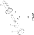
- FIG. 2A presents an assembly view of an exemplary feed-antenna subassembly, in accordance with an embodiment of the present invention.
- feed-antenna subassembly 110 includes a feed cap 112, a sub-reflector 114, a PCB 116, a light divider 118, and a feed body 119.
- Feed cap 112 and feed body 119 form an enclosed cavity and house sub-reflector 114 and PCB 116.
- PCB 116 includes electronics components of the radio, which can include but are not limited to: filters, amplifiers, modulators, demodulators, and network/power interfaces, etc.
- PCB 116 includes an Ethernet interface that provides network connection and power (via power over Ethernet (PoE)) to other radio components on PCB 116.
- Sub-reflector 114 couples to the receiving and transmitting circuitry on PCB 116, and collects radio waves from or reflects radio waves to dish reflector 120.
- feed body 119 is transparent to radio waves. Based on the operating frequency, sub-reflector 114 may have different shapes and sizes.
- other components within feed-antenna subassembly 110 such as feed cap 112 and feed body 119, also vary in size and/or shape according to the operating frequency of the radio. However, the way that feed antenna subassembly 110 coupled to dish reflector 120 and rear housing 140 remains the same.
- sub-reflector 114 not only ensures the radio being compact in size, but also eliminates the need for an external cable to connect the sub-reflector to other radio components, thus obviating the need to tune antenna when transmitting.
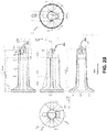
- FIG. 2B illustrates a detailed mechanical drawing of an exemplary feed body, in accordance with an embodiment of the present invention. More specifically, FIG. 2B provides exemplary dimensions of the feed body. In the example shown in FIG. 2B , all lengths are expressed in millimeters.
- the feed body is made of hard plastic material, such as polyvinyl chloride (PVC).
- the top center drawing shows the top view of the feed body.
- the middle center drawing shows the side view of the feed body, and the bottom center drawing shows the cross-sectional view of the feed body along the cutting plane A-A.
- the right and left drawings are the front and back views of the front opening of the feed body, respectively.
- Opening 202 provides physical access to a port, such as an RJ48 port on the PCB enclosed inside the feed body.
- a user can connect an Ethernet cable to the RJ48 port on the PCB, thus providing network connection and power to components on the PCB.
- Push latch 204 includes a portion that extrudes out of the surface of the feed body. This extruded portion latches to an opening in the rear housing, thus coupling the feed body (and, therefore, the feed-antenna subassembly) with the rear housing.
- an L-shaped slit separating push latch 204 from other portions of the feed body acts like a spring, making it possible for push latch 204 to be pushed inward by a person's thumb or by the sidewall of the rear housing.
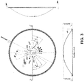
- FIG. 3 illustrates a detailed mechanical drawing of an exemplary dish reflector, in accordance with an embodiment of the present invention.
- the center drawing provides a front view of the dish reflector
- the right-hand drawing provides a side view of the dish reflector
- the bottom drawing provides a cross-sectional view of the dish reflector along cutting plane A-A.
- all lengths are in millimeters and angles are in degrees.
- the dish reflector includes a large center opening 302 and a number of slots 304-308.
- Large center opening 302 is designed in such a way that allows the back end of the feed body to go through large center opening 302 to couple to the rear housing.
- Slots 304-308 enable secure attachment of the pole-mounting bracket.
- a slot is shaped like a deformed L with the back of the L being wider and shorter than the back of a normal L. Note that the inner and outer edges of slots are aligned with latitude lines on the dish to enable rotation of inserted latches.
- the arc length of the base of the L is at least twice that of the back of the L.
- a dish reflector may include additional or fewer slots, or the slots may be located along different latitude lines (in the example shown in FIG. 3 , all slots are located on a same latitude line), as long as the slots enable latching between the pole-mounting bracket and the dish reflector.
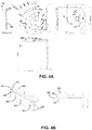
- FIG. 4A illustrates a detailed mechanical drawing of an exemplary pole-mounting bracket, in accordance with an embodiment of the present invention.
- pole-mounting bracket is made of a metal material, such as aluminum or stainless steel.
- the top center drawing shows the front view (looking into the back of the dish reflector in reference to FIG. 1 ) of the pole-mounting bracket.
- the bottom center drawing shows the top view of the pole-mounting bracket, the right-hand drawing shows the left view of the pole-mounting bracket, and the left-hand drawing shows the cross-sectional view of the pole-mounting bracket across cutting plane A-A.
- the pole-mounting bracket is an L-shaped bracket.
- the base of the L is attached to the back surface of the dish reflector.
- FIG. 4A illustrates that the base of the pole-mounting bracket is curved to match the curvature on the dish reflector.
- the base plate of the pole-mounted bracket includes a large center opening 402, and a number of latches 404-408. Note that, compare with the large center opening on the dish reflector, large center opening 402 has a similar shape and a larger size, thus allowing a portion of the rear housing to extrude through large center opening 402 to couple to the front side of the dish reflector.
- the latches (such as latches 404, 406, and 408) on the base plate of the pole-mounting bracket extrude out of the surface of the base plate and tilt slightly toward the base plate.
- Each latch is shaped as a deformed L with a narrower back portion and a wider base portion. The back of the L is attached to the base plate at an angle.
- the locations of the latches correspond to the locations of slots (such as slots 304, 306, and 308) on the dish reflector.
- these latches (which are made of metal) are non-bendable.
- a user can attach the base plate of the pole-mounting bracket to the back of the dish reflector by inserting the latches on the base plate into the L-shaped slots on the dish reflector. More specifically, the latches can be inserted into the slots through the wider portion of the slots (the back of the L). The tilted angle and the wider base of the extruded latches prevent these latches from being able to be inserted into the slots through their narrower portion. Afterwards, the user can rotate the base plate of the pole-mounting bracket against the dish reflector to let the latches (more precisely, the narrower back portion of the L) slide into the narrower portion of the slots.
- the wider base portion of a latch latches to the front surface of the dish reflector, thus preventing the pole-mounting bracket from being pulled away from the reflector.
- a rotation is needed to slide the latches out of the narrow portion of the slots and into the wider portion of the slots on the dish reflector. Note that while attaching the pole-mounting bracket to the reflector dish, one needs to make sure the center openings on these two pieces are aligned.
- FIG. 4A also illustrates that the back plate of the pole-mounting bracket includes a round hole 410 and a curved slot 412. Round hole 410 and curved slot 412 enable coupling between the pole-mounting bracket and a pole clamp via a U-bolt.
- FIG. 4B illustrates an exemplary pole clamp, in accordance with an embodiment of the present invention. The left-hand drawing in FIG. 4B shows the pole clamp in 3-D, and the right-hand drawing shows the side view of the pole clamp.
- the pole clamp includes a U-shaped clamp body 422 and a pair of jaws 424 and 426.
- the U-shaped clamp body 422 further includes a clamp base 434 on one side of the U and a lance 436 on the other.
- Clamp base 434 supports jaws 424 and 426.
- lance 436 acts as a larger washer for to prevent fasteners (not shown in the figure) from scraping paint of the back plate of the pole-mounting bracket, which, once installed, is sandwiched between clamp base 434 and lance 436, via the opening of the U. Note that such a design helps to maintain protections of the pole-mounting bracket from corrosions in an outdoor environment.
- the positions of through holes 428 and 430 correspond to the positions of hole 410 and slot 412 on the back plate of the pole-mounting bracket.
- a U-shaped bolt along with matching nuts can be used to couple the pole clamp and the back plate of the pole-mounting with the ends of the U going through holes 428 and 430 on the pole clamp and corresponding slot 412 and hole 410 on the back plate of the pole-mounting bracket.
- one end of the U-bolt passes through holes 410 and 430 and forms a pivot point, and the other end of the U-bolt passes through hole 430 and slot 412, making it possible for the pole clamp to rotate along slot 412 against the pivot point.
- the bottom of the U of the U-shaped bolt and jaws 424 and 426 form a ring-like structure that can attach to the outer surface of a circular-shaped pole.
- jaws 424 and 426 include step-shaped surfaces for better gripping onto the pole. Because the pole clamp and the U-bolt are clamped onto the pole and form a horizontal plane, the pole-mounting bracket can tilt relative to this horizontal plane in a range that is defined by slot 412.
- the position of slot 432 corresponds to the angle markings on the back plate of the pole-mounting bracket, thus allowing a user to see at what angle the pole-mounting bracket, and thus the antenna, is mounted onto the pole.
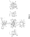
- FIG. 5 illustrates a detailed mechanical drawing of an exemplary rear housing, in accordance with an embodiment of the present invention.
- the rear housing is made of a hard plastic material, such as PVC.
- FIG. 5 shows six different views of the rear housing, including the front view (looking away from the back of the dish reflector in reference to FIG. 1 ) of the rear housing (middle row, second to the left); the bottom view (top row); the top view (bottom row); the right-side view (middle row, far left); the left-side view (middle row, second to the right); and the rear view (middle row, far right) of the rear housing.
- the rear housing includes a center cavity 502.
- the size and shape of center cavity 502 correspond to the back end of the feed body, thus allowing the feed-antenna subassembly to be inserted and snugly fitted into center cavity 502.
- the sidewall of center cavity 502 includes a small opening 504 and large opening 506.
- the location and size of small opening 504 correspond to push latch 204 located on the feed body. When the feed body is inserted into center cavity 502, push latch 204 is pushed into small opening 504 and latches to the sidewall of center cavity 502, thus enabling secure coupling between the feed-antenna subassembly and the rear housing.
- center cavity 502 may also include a number of slots that fit a number of extrusions on the feed body, thus ensuring better fitting and coupling between the back end of the feed body and center cavity 502.
- the rear housing also includes a side cover that fits to slot 508 and covers small opening 504 and large opening 506 while allowing a cable to couple to the RJ48 port on the PCB.
- the rear housing In addition to housing the back end of the feed-antenna subassembly, the rear housing also provides support to the feed-antenna subassembly by attaching itself securely to the dish reflector. In addition, the attachment of the rear housing also locks the coupling between the dish reflector and the pole-mounting bracket. More specifically, the coupling between the rear housing and the dish reflector is provided by a number of push latches, including push latches 512, 514, and 516. Note that a respective push latch, such as push latch 512, can be formed by cutting trenches on both sides of a small rectangular portion of the sidewall of center cavity 502, separating that rectangular portion from the rest of the sidewall. Each latch also has a tapered front end.
- the height of outer shell 510 is designed to be lower than the height of the sidewall of center cavity 502.
- the height difference is determined by the thickness of the base plate of the pole-mounting bracket and the thickness of the dish reflector.
- Outer shell 510 also includes two extruding circular studs 522 and 524.
- circular studs 522 and 524 When pushed against the backside of the dish reflector, circular studs 522 and 524 fit into corresponding holes situated on the base plate of the pole-mounting bracket and holes situated on the dish reflector. Note that once circular studs 522 and 524 are inserted into holes on the base plate of the pole-mounting bracket and holes on the dish reflector, any rotation of the pole-mounting bracket relative to the dish reflector is prevented.
- circular studs 522 and 524 can serve as precision locator pins, which prevent any possible slip between the assembly joints, such as a slip between the dish reflector and the base plate.
- circular studs 522 and 524 Another function of circular studs 522 and 524 is to accommodate for tolerances in the fabrication of the different antenna components.
- the non-circular shape of the center openings and center cavity 502 also help prevent possible slips between the dish reflector and the base plate of the pole-mounting bracket.
- the attachment of the rear housing to the dish reflector via push latches 512-516 serves an additional purpose of locking the pole-mounting bracket to the dish reflector.
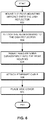
- FIG. 6 presents a flowchart illustrating an exemplary process of assembling a dish antenna assembly, in accordance with an embodiment of the present invention.
- the user first mounts the pole-mounting bracket onto the backside of the dish reflector (operation 602).
- the latches that extrude out of the surface of the base plate of the pole-mounting bracket are inserted into L-shaped slots on the bottom of the dish reflector, and the base plate is then rotated along the slot to allow the narrow back portion of the latches to slide into the narrow portion of the L-shaped slots.
- the user can attach the rear housing to the dish reflector (operation 604).
- the rear housing is attached to the dish reflector by a number of push latches that are pushed through center openings on both the dish reflector and the base plate of the pole-mounting bracket.
- the push latches latch to the edge of the center opening on the dish reflector.
- the number and location of the push latches may be different from the example shown in FIG. 5 .
- a pair of studs on the outer shell of the rear housing is pushed into corresponding holes on both the dish reflector and the base plate, thus locking the relative positions of the base plate and the dish reflector. As a result, one needs to remove the rear housing before decoupling the base plate and the dish reflector.
- the user can insert the back end of the feed-antenna subassembly into the center cavity of the rear housing (operation 606).
- a push latch can be used to securely attach the feed-antenna subassembly to the rear housing.
- a user can then connect a cable, such as an Ethernet cable, to the network/power port (which can include an RJ48 connector) on the PCB housed within the feed-antenna subassembly (operation 608).
- the network/power port is accessible via openings on both the feed body and the rear housing.
- the user can put the side cover of the rear housing in place (operation 610), and the dish antenna is ready to be mounted onto a pole.
- the assembly process includes simple inserting and clicking operations. A user can perform these operations without the need for any tools.
- the dissembly process involves detaching the push latches and can also be performed without using any tools.
- FIG. 7 presents an assembly view of an exemplary grid antenna assembly, in accordance with an embodiment of the present invention.
- grid antenna assembly 700 includes a feed-antenna subassembly 710, a grid reflector 720, a pole-mounting bracket 730, an optional extension tube 740, and a rear housing 750.
- feed-antenna subassembly 710 is similar to that of the feed-antenna subassembly in the dish antenna, except that the size and shape of feed-antenna subassembly 710 are carefully designed to work with grid reflector 720.
- a user can choose feed-antenna subassemblies with different sizes and shapes. These different types of feed-antenna subassemblies are designed to fit into rear housing 750 and/or extension tube 740.
- Grid reflector 720 includes a grill of parallel wires. When the wires are oriented horizontally, a horizontal polarization is achieved; when the wires are oriented vertically, a vertical polarization is achieved. Note that the polarization of a grid antenna needs to match the orientation of its corresponding device (horizontal to horizontal, vertical to vertical). For example, if the transmitting device has a horizontal polarization, the receiving antenna needs to be oriented so that it has a horizontal polarization as well.
- Pole-mounting bracket 730 also has a similar structure to that of the pole-mounting bracket in the dish antenna assembly.
- a slide latch mechanism can be used to attach the base plate of pole-mounting bracket 730 onto grid reflector 720. More specifically, grid reflector 720 includes a mounting bracket having a number of slide bars, and the base plate of pole-mounting bracket 730 includes a number of latches that match the slide bars. A user can slide the base plate of pole-mounting bracket 730 against the mounting bracket on grid reflector 720 to attach pole-mounting bracket 730 to grid reflector 720.
- rear housing 750 is snapped into place on the mounting bracket of grid reflector 720.
- Rear housing 750 is similar to the rear housing in the dish antenna assembly.
- a number of push latches on rear housing 750 latch to the edge of a center opening on the mounting bracket of grid reflector 720 when these push latches are pushed through such a center opening.
- rear housing 750 not only securely attaches to grid reflector 720, but also locks the base plate of pole-mounting bracket 730 to the mounting bracket on grid reflector 720.
- rear housing 750 to the mounting bracket on grid reflector 720 prevents the base plate of pole-mounting bracket 730 from sliding off the mounting bracket on grid reflector 720.
- Rear housing 750 includes a center cavity that houses feed-antenna subassembly 710.
- an extension tube 740 is used for coupling feed-antenna subassembly 710 and rear housing 750.
- extension tube 740 provides additional distance needed between the sub-reflector in feed-antenna subassembly 710 and grid reflector 720.
- extension tube 740 is needed, it is inserted into rear housing 750, and the back end of feed-antenna subassembly 710 is inserted into extension tube 740. Otherwise, the back end of feed-antenna subassembly 710 is directly inserted into rear housing 750.
- push latches can be used to couple feed-antenna subassembly 710 to rear housing 750 or extension tube 740.
- FIG. 8 illustrates the assembled grid antenna viewed from different angles, in accordance with an embodiment of the present invention.
- the middle drawing in the center row illustrates the back view of the grid antenna.
- the middle drawings in the top and bottom rows illustrate the top and bottom views of the grid antenna, respectively.
- the left-hand and right-hand drawings in the middle row illustrate the right-side and left-side views of the grid antenna, respectively.
- the left-hand and right-hand drawings in the top row are isometric views of the grid antenna.
- the grid antenna assembly has a different shape and dimensions compared with the dish antenna assembly, the basic design principle for these two antenna systems is similar. Both systems provide a high-speed, long-range radio that can be used for wireless communication. Various electronic components of the radio system are placed onto a single PCB and the PCB is enclosed in the feed-antenna subassembly. Such a design not only ensures the radio being compact in size, but also eliminates the need for an external cable that connects the sub-reflector and other radio components. The various components, including the reflector, the feed-antenna subassembly, the pole-mounting bracket, and the rear housing, are assembled in such a way that no special hardware is needed.
- the rear housing includes a locking mechanism that can lock the coupling between the pole-mounting bracket and the reflector. Such a locking mechanism is activated when the rear housing is latched onto the reflector, and can only be deactivated by removing the rear housing.
Landscapes
- Physics & Mathematics (AREA)
- Electromagnetism (AREA)
- Aerials With Secondary Devices (AREA)
- Support Of Aerials (AREA)
- Variable-Direction Aerials And Aerial Arrays (AREA)
Claims (13)
- Antennenbaugruppe (100), umfassend:einen Reflektor (120), der eine zentrale Öffnung, eine Befestigungsöffnung, eine konvexe Seite und eine konkave Seite umfasst, wobei die konkave Seite die Vorderseite des Reflektors ist;ein rückseitiges Gehäuse (140), das auf der konvexen Seite des Reflektors angebracht ist, wobei das rückseitige Gehäuse einen zentralen Hohlraum (502) umfasst;eine Einspeiseantennenunterbaugruppe (110), die auf der konkaven Seite des Reflektors angebracht ist, wobei die Einspeiseantennenunterbaugruppe eine Einspeiseröhre umfasst, wobei ein proximales Ende der Einspeiseröhre funktionsfähig ist, um in den zentralen Hohlraum des rückseitigen Gehäuses eingefügt und mit diesem verbunden zu werden, wobei der Reflektor zwischen der Einspeiseantennenunterbaugruppe und dem rückseitigen Gehäuse angebracht ist; undeinen Transceiver-Schaltkreis, der innerhalb der Einspeiseröhre angebracht ist, wobei der Transceiver-Schaltkreis mit einem Datenanschluss verbunden ist, der von einer proximalen Seite der Einspeiseantennenunterbaugruppe zugänglich ist, wobei die Antennenbaugruppe so konfiguriert ist, dass, wenn die Einspeiseantennenunterbaugruppe an die konkave Seite des Reflektors montiert wird, der Datenanschluss auf der konvexen Seite des Reflektors freigelegt wird,dadurch gekennzeichnet, dassdas rückseitige Gehäuse außerdem einen Schieberiegel (204) umfasst, der funktionsfähig ist, um die Befestigungsöffnung des Reflektors zu durchqueren und in die Vorderseite des Reflektors einzugreifen.
- Antennenbaugruppe nach Anspruch 1, wobei der Transceiver-Schaltkreis eine gedruckte Leiterplatte (Printed Circuit Board, PCB) für einen Sender- und Empfängerschaltkreis umfasst, und wobei der Datenanschluss auf die PCB montiert ist.
- Antennenbaugruppe nach Anspruch 1, wobei der Transceiver-Schaltkreis konfiguriert ist zum Empfangen einer Stromversorgung über den Datenanschluss.
- Antennenbaugruppe nach Anspruch 1, wobei der Datenanschluss einen Ethernet-Anschluss aufweist und wobei der Ethernet-Anschluss konfiguriert ist, um eine Stromversorgung über Ethernet zu erlauben.
- Antennenbaugruppe nach Anspruch 1, die außerdem einen Unterreflektor innerhalb der Einspeiseröhre in der Nähe des distalen Endes der Einspeiseantennenunterbaugruppe umfasst.
- Antennenbaugruppe nach Anspruch 1, die außerdem einen Einspeisedeckel an einem distalen Ende der Einspeiseantennenunterbaugruppe umfasst.
- Antennenbaugruppe nach Anspruch 1, wobei die Einspeiseantennenunterbaugruppe außerdem einen Schieberiegel umfasst, der konfiguriert ist, um den zentralen Hohlraum des rückseitigen Gehäuses zu durchqueren und in einer Riegelöffnung des rückseitigen Gehäuses einzugreifen.
- Antennenbaugruppe nach Anspruch 7, die so konfiguriert ist, dass für ein Entfernen der Einspeiseantennenunterbaugruppe und des rückseitigen Gehäuses ein vorheriges Entriegeln des Schieberiegels von dem rückseitigen Gehäuse erforderlich ist.
- Antennenbaugruppe nach Anspruch 1, wobei die zentrale Öffnung des Reflektors eine Form aufweist, die mit einem Profil des proximalen Endes des rückseitigen Gehäuses übereinstimmt.
- Antennenbaugruppe nach Anspruch 1, die so konfiguriert ist, dass das Einfügen des Schieberiegels in die Befestigungsöffnung verhindert, dass das rückseitige Gehäuse von dem Reflektor abgetrennt wird.
- Antennenbaugruppe nach Anspruch 1, die außerdem umfasst:
eine Stabmontagehalterung, die eine Basisplatte und eine Rückplatte umfasst, wobei die Rückplatte mindestens einen Klammerschlitz aufweist, wobei die Basisplatte zwischen dem Reflektor und dem rückseitigen Gehäuse angebracht ist, und wobei die Basisplatte funktionsfähig ist, um mit dem Reflektor in einer Weise verbunden zu werden, dass für ein Abtrennen der Basisplatte von dem Reflektor zuvor ein Abtrennen der Einspeiseantennenunterbaugruppe von dem rückseitigen Gehäuse erforderlich ist. - Antennenbaugruppe nach Anspruch 11, die außerdem umfasst:
eine Stabklammer zum Montieren eines Reflektors an einen Stab, wobei ein Bolzen der Stabklammer in den Klammerschlitz eingefügt wird. - Antennenbaugruppe nach Anspruch 11, wobei der Klammerschlitz eine lang gestreckte Form mit einer Krümmung aufweist, die erlaubt, dass die Stabklammer innerhalb eines vorbestimmten Bereichs in Bezug auf einen Drehpunkt der Rückplatte entlang des Klammerschlitzes gedreht wird.
Priority Applications (1)
| Application Number | Priority Date | Filing Date | Title |
|---|---|---|---|
| PL18156517T PL3340374T3 (pl) | 2012-04-06 | 2013-04-04 | Zespół anteny do komunikacji bezprzewodowej o dużym zasiągu, z wysoką szybkością |
Applications Claiming Priority (5)
| Application Number | Priority Date | Filing Date | Title |
|---|---|---|---|
| US201261621396P | 2012-04-06 | 2012-04-06 | |
| US201261621401P | 2012-04-06 | 2012-04-06 | |
| US13/839,473 US9225071B2 (en) | 2012-04-06 | 2013-03-15 | Antenna assembly for long-range high-speed wireless communications |
| EP13716932.2A EP2834879B8 (de) | 2012-04-06 | 2013-04-04 | Antennenanordnung für schnelle drahtlose kommunikation in einem weiten bereich |
| PCT/US2013/035214 WO2013152158A1 (en) | 2012-04-06 | 2013-04-04 | Antenna assembly for long-range high-speed wireless communication |
Related Parent Applications (2)
| Application Number | Title | Priority Date | Filing Date |
|---|---|---|---|
| EP13716932.2A Division EP2834879B8 (de) | 2012-04-06 | 2013-04-04 | Antennenanordnung für schnelle drahtlose kommunikation in einem weiten bereich |
| EP13716932.2A Division-Into EP2834879B8 (de) | 2012-04-06 | 2013-04-04 | Antennenanordnung für schnelle drahtlose kommunikation in einem weiten bereich |
Publications (2)
| Publication Number | Publication Date |
|---|---|
| EP3340374A1 EP3340374A1 (de) | 2018-06-27 |
| EP3340374B1 true EP3340374B1 (de) | 2020-05-27 |
Family
ID=48128629
Family Applications (2)
| Application Number | Title | Priority Date | Filing Date |
|---|---|---|---|
| EP13716932.2A Active EP2834879B8 (de) | 2012-04-06 | 2013-04-04 | Antennenanordnung für schnelle drahtlose kommunikation in einem weiten bereich |
| EP18156517.7A Active EP3340374B1 (de) | 2012-04-06 | 2013-04-04 | Antennenanordnung zur schnellen drahtloskommunikation in einem weiten bereich |
Family Applications Before (1)
| Application Number | Title | Priority Date | Filing Date |
|---|---|---|---|
| EP13716932.2A Active EP2834879B8 (de) | 2012-04-06 | 2013-04-04 | Antennenanordnung für schnelle drahtlose kommunikation in einem weiten bereich |
Country Status (19)
| Country | Link |
|---|---|
| US (3) | US9225071B2 (de) |
| EP (2) | EP2834879B8 (de) |
| CN (3) | CN103384030B (de) |
| AR (1) | AR094133A1 (de) |
| BR (1) | BR112014024803B1 (de) |
| CY (2) | CY1120519T1 (de) |
| DK (1) | DK2834879T3 (de) |
| ES (2) | ES2671242T3 (de) |
| HR (1) | HRP20180892T1 (de) |
| HU (1) | HUE037561T2 (de) |
| LT (2) | LT3340374T (de) |
| PL (2) | PL2834879T3 (de) |
| PT (1) | PT2834879T (de) |
| RS (1) | RS57391B1 (de) |
| SI (1) | SI2834879T1 (de) |
| SM (1) | SMT201800283T1 (de) |
| TR (1) | TR201807560T4 (de) |
| TW (1) | TWI577080B (de) |
| WO (1) | WO2013152158A1 (de) |
Families Citing this family (33)
| Publication number | Priority date | Publication date | Assignee | Title |
|---|---|---|---|---|
| US8836601B2 (en) | 2013-02-04 | 2014-09-16 | Ubiquiti Networks, Inc. | Dual receiver/transmitter radio devices with choke |
| US9496620B2 (en) | 2013-02-04 | 2016-11-15 | Ubiquiti Networks, Inc. | Radio system for long-range high-speed wireless communication |
| US9634373B2 (en) | 2009-06-04 | 2017-04-25 | Ubiquiti Networks, Inc. | Antenna isolation shrouds and reflectors |
| US9225071B2 (en) * | 2012-04-06 | 2015-12-29 | Ubiquiti Networks, Inc. | Antenna assembly for long-range high-speed wireless communications |
| US9543635B2 (en) | 2013-02-04 | 2017-01-10 | Ubiquiti Networks, Inc. | Operation of radio devices for long-range high-speed wireless communication |
| US20160218406A1 (en) | 2013-02-04 | 2016-07-28 | John R. Sanford | Coaxial rf dual-polarized waveguide filter and method |
| US9397820B2 (en) | 2013-02-04 | 2016-07-19 | Ubiquiti Networks, Inc. | Agile duplexing wireless radio devices |
| US9531067B2 (en) | 2013-02-08 | 2016-12-27 | Ubiquiti Networks, Inc. | Adjustable-tilt housing with flattened dome shape, array antenna, and bracket mount |
| USD744986S1 (en) | 2013-09-06 | 2015-12-08 | Ubiquiti Networks, Inc. | Wireless transmission station |
| US9191037B2 (en) | 2013-10-11 | 2015-11-17 | Ubiquiti Networks, Inc. | Wireless radio system optimization by persistent spectrum analysis |
| WO2015076887A1 (en) * | 2013-11-19 | 2015-05-28 | Commscope Technologies Llc | Feed assembly interconnection |
| USD803817S1 (en) | 2014-01-31 | 2017-11-28 | Ubiquiti Networks, Inc. | Duplex, point-to-point wireless radio antenna system |
| EP3114884B1 (de) | 2014-03-07 | 2019-10-23 | Ubiquiti Inc. | Cloud-vorrichtung-identifizierung und -authentifizierung |
| WO2015134755A2 (en) | 2014-03-07 | 2015-09-11 | Ubiquiti Networks, Inc. | Devices and methods for networked living and work spaces |
| US9368870B2 (en) | 2014-03-17 | 2016-06-14 | Ubiquiti Networks, Inc. | Methods of operating an access point using a plurality of directional beams |
| EP3127187B1 (de) | 2014-04-01 | 2020-11-11 | Ubiquiti Inc. | Antennenanordnung |
| CN106233797B (zh) | 2014-06-30 | 2019-12-13 | 优倍快网络公司 | 无线电设备对准工具及方法 |
| US9893398B2 (en) | 2014-10-14 | 2018-02-13 | RF elements s.r.o. | Quick connect waveguide coupler using pertubations rotatably movable through slots between a locked position and an unlocked position |
| ES2868348T3 (es) * | 2014-10-14 | 2021-10-21 | Ubiquiti Inc | Cubiertas de aislamiento de señal y reflectores para antena |
| US9847584B2 (en) * | 2014-12-02 | 2017-12-19 | Ubiquiti Networks, Inc. | Multi-panel antenna system |
| WO2016134751A1 (en) * | 2015-02-24 | 2016-09-01 | Fraunhofer-Gesellschaft zur Förderung der angewandten Forschung e.V. | Integrated transceiver with focusing antenna |
| USD800100S1 (en) | 2015-05-01 | 2017-10-17 | Ubiquiti Networks, Inc. | Multiple panel reflector dish antenna |
| WO2017044924A1 (en) | 2015-09-11 | 2017-03-16 | Ubiquiti Networks, Inc. | Compact public address access point apparatuses |
| CN106299586B (zh) * | 2016-08-23 | 2018-10-09 | 中国电子科技集团公司第二十九研究所 | 一种用于阵列化天线单元装卸定位的快锁结构、天线单元及安装基座 |
| WO2018191383A1 (en) * | 2017-04-11 | 2018-10-18 | Carpe Diem Technologies, Inc. | System and method of manufacturing a cylindrical nanoimprint lithography master |
| US10587031B2 (en) | 2017-05-04 | 2020-03-10 | RF Elements SRO | Quick coupling assemblies |
| US10778333B2 (en) | 2017-05-17 | 2020-09-15 | RF elements s.r.o. | Modular electromagnetic antenna assemblies and methods of assembling and/or disassembling |
| DE102017116077B4 (de) * | 2017-07-17 | 2019-11-21 | Reel Reinheimer Elektronik Gmbh | Verbindungsvorrichtung an Antennengehäusen |
| US10651523B2 (en) | 2018-04-12 | 2020-05-12 | Transtector Systems, Inc. | Waveguide connector assembly having bearings engageable by a movable sleeve to allow or prevent axial movement of the connector assembly, and an antenna and a polarizer, respectively formed therefrom |
| US10847892B2 (en) * | 2019-03-18 | 2020-11-24 | Antenna World Inc. | Wide band log periodic reflector antenna for cellular and Wifi |
| CN111673445A (zh) * | 2020-07-06 | 2020-09-18 | 一飞智控(天津)科技有限公司 | 一种无人机天线装配方法、装置及使用的拧紧工装 |
| KR102405344B1 (ko) * | 2021-05-14 | 2022-06-07 | 가온미디어 주식회사 | 밀리미터파 수신을 위한 옥외 설치형 안테나 장치 |
| CN115000674B (zh) * | 2021-09-07 | 2023-04-28 | 荣耀终端有限公司 | 一种电子设备 |
Family Cites Families (21)
| Publication number | Priority date | Publication date | Assignee | Title |
|---|---|---|---|---|
| US2478913A (en) * | 1944-02-07 | 1949-08-16 | Stromberg Carlson Co | Dipole antenna |
| WO1992021159A1 (en) * | 1991-05-13 | 1992-11-26 | Thomson Consumer Electronics S.A. | Radiowave antenna system |
| US5760749A (en) * | 1994-03-17 | 1998-06-02 | Fujitsu Limited | Antenna integral-type transmitter/receiver system |
| US5508712A (en) * | 1994-03-28 | 1996-04-16 | P-Com, Inc. | Self-aligning wave guide interface |
| JP2853658B2 (ja) | 1996-06-04 | 1999-02-03 | 日本電気株式会社 | アンテナ支持構造 |
| GB9626144D0 (en) * | 1996-12-17 | 1997-02-05 | Lenson Heath Triax Limited | Antennas |
| US6507324B2 (en) * | 2001-02-06 | 2003-01-14 | Harris Broadband Wireless Access, Inc. | Antenna quick connect/disconnect system and method |
| US6685383B2 (en) * | 2001-11-02 | 2004-02-03 | Radio Frequency Systems Inc. | Antenna and radio interface |
| US6714171B2 (en) * | 2002-06-14 | 2004-03-30 | Centurion Wireless Technologies, Inc. | Antenna mounting apparatuses and methods |
| JP4167506B2 (ja) * | 2003-02-03 | 2008-10-15 | 株式会社村上開明堂 | ディスプレイの方向調整装置 |
| US6985120B2 (en) * | 2003-07-25 | 2006-01-10 | Andrew Corporation | Reflector antenna with injection molded feed assembly |
| US7212172B2 (en) * | 2004-06-30 | 2007-05-01 | Harris Stratex Networks Operating Corporation | System and method for a radio/antenna interface |
| CN100517864C (zh) * | 2005-09-29 | 2009-07-22 | 广东南方通信建设股份有限公司 | 移动通信基站使用的天线 |
| US7800551B2 (en) * | 2006-06-27 | 2010-09-21 | Mccown James Charles | Passive parabolic antenna, wireless communication system and method of boosting signal strength of a subscriber module antenna |
| CN201204785Y (zh) * | 2008-05-22 | 2009-03-04 | 纬创资通股份有限公司 | 散热器的固定装置 |
| US8466847B2 (en) * | 2009-06-04 | 2013-06-18 | Ubiquiti Networks, Inc. | Microwave system |
| TR201002243A2 (tr) * | 2010-03-24 | 2010-12-21 | Sab Elektroni̇k Maki̇na Ve Dayanikli Tüketi̇m Mallari Sanayi̇ Ti̇caret Anoni̇m Şi̇rketi̇ | Çanak anten bağlantısında yenilik. |
| US8674885B2 (en) * | 2010-08-31 | 2014-03-18 | Siklu Communication ltd. | Systems for interfacing waveguide antenna feeds with printed circuit boards |
| US9240626B2 (en) * | 2011-07-21 | 2016-01-19 | Pro Brand International, Inc. | Snap attachment for reflector mounting |
| US9225071B2 (en) * | 2012-04-06 | 2015-12-29 | Ubiquiti Networks, Inc. | Antenna assembly for long-range high-speed wireless communications |
| US20130313208A1 (en) * | 2012-05-24 | 2013-11-28 | Microelectronics Technology, Inc. | Outdoor unit system and holder for outdoor unit |
-
2013
- 2013-03-15 US US13/839,473 patent/US9225071B2/en active Active
- 2013-04-03 TW TW102112160A patent/TWI577080B/zh active
- 2013-04-03 CN CN201310116485.6A patent/CN103384030B/zh active Active
- 2013-04-03 CN CN201610592840.0A patent/CN106257751A/zh active Pending
- 2013-04-03 CN CN201320166344.0U patent/CN203398307U/zh not_active Withdrawn - After Issue
- 2013-04-04 PL PL13716932T patent/PL2834879T3/pl unknown
- 2013-04-04 SI SI201331058T patent/SI2834879T1/sl unknown
- 2013-04-04 DK DK13716932.2T patent/DK2834879T3/en active
- 2013-04-04 LT LTEP18156517.7T patent/LT3340374T/lt unknown
- 2013-04-04 PL PL18156517T patent/PL3340374T3/pl unknown
- 2013-04-04 PT PT137169322T patent/PT2834879T/pt unknown
- 2013-04-04 HU HUE13716932A patent/HUE037561T2/hu unknown
- 2013-04-04 LT LTEP13716932.2T patent/LT2834879T/lt unknown
- 2013-04-04 RS RS20180663A patent/RS57391B1/sr unknown
- 2013-04-04 HR HRP20180892TT patent/HRP20180892T1/hr unknown
- 2013-04-04 SM SM20180283T patent/SMT201800283T1/it unknown
- 2013-04-04 ES ES13716932.2T patent/ES2671242T3/es active Active
- 2013-04-04 TR TR2018/07560T patent/TR201807560T4/tr unknown
- 2013-04-04 EP EP13716932.2A patent/EP2834879B8/de active Active
- 2013-04-04 ES ES18156517T patent/ES2805953T3/es active Active
- 2013-04-04 EP EP18156517.7A patent/EP3340374B1/de active Active
- 2013-04-04 BR BR112014024803-6A patent/BR112014024803B1/pt active IP Right Grant
- 2013-04-04 WO PCT/US2013/035214 patent/WO2013152158A1/en not_active Ceased
- 2013-04-08 AR ARP130101132A patent/AR094133A1/es active IP Right Grant
-
2015
- 2015-12-02 US US14/957,483 patent/US10243275B2/en active Active
-
2018
- 2018-06-06 CY CY20181100588T patent/CY1120519T1/el unknown
-
2019
- 2019-02-14 US US16/276,236 patent/US10418718B2/en active Active
-
2020
- 2020-07-13 CY CY20201100644T patent/CY1123402T1/el unknown
Non-Patent Citations (1)
| Title |
|---|
| None * |
Also Published As
Similar Documents
| Publication | Publication Date | Title |
|---|---|---|
| EP3340374B1 (de) | Antennenanordnung zur schnellen drahtloskommunikation in einem weiten bereich | |
| EP2710743B1 (de) | Fusioniertes netzwerk innerhalb eines gebäudes | |
| EP2710691B1 (de) | Fernsteckdosenvorrichtung | |
| US6174205B1 (en) | Communication card extension and adapter port | |
| EP3227957B1 (de) | Antennensystem mit mehreren paneelen | |
| US5714963A (en) | Antenna-to-radio quick-connect support device | |
| US6525620B1 (en) | Capacitive signal coupling device | |
| WO2012158581A2 (en) | Antenna assembly for converged in-building network | |
| JP2005503049A (ja) | モジュール型二指向性アンテナ | |
| EP3832795B1 (de) | Antennenvorrichtung für basisstation und adapter dafür | |
| US6473043B1 (en) | Antenna assembly | |
| US6373438B1 (en) | Antenna assembly with improved mechanical antenna casing | |
| JP3064212B2 (ja) | アンテナ装置 | |
| US6940472B2 (en) | Universal antenna adapter | |
| JP2017143403A (ja) | 偏波共用アンテナ | |
| KR100527328B1 (ko) | 위성 라디오용 입출력 커넥터 | |
| CN115550253A (zh) | 基于介质透镜天线的路由器 | |
| FI113591B (fi) | Antennijärjestely |
Legal Events
| Date | Code | Title | Description |
|---|---|---|---|
| PUAI | Public reference made under article 153(3) epc to a published international application that has entered the european phase |
Free format text: ORIGINAL CODE: 0009012 |
|
| STAA | Information on the status of an ep patent application or granted ep patent |
Free format text: STATUS: THE APPLICATION HAS BEEN PUBLISHED |
|
| AC | Divisional application: reference to earlier application |
Ref document number: 2834879 Country of ref document: EP Kind code of ref document: P |
|
| AK | Designated contracting states |
Kind code of ref document: A1 Designated state(s): AL AT BE BG CH CY CZ DE DK EE ES FI FR GB GR HR HU IE IS IT LI LT LU LV MC MK MT NL NO PL PT RO RS SE SI SK SM TR |
|
| STAA | Information on the status of an ep patent application or granted ep patent |
Free format text: STATUS: REQUEST FOR EXAMINATION WAS MADE |
|
| 17P | Request for examination filed |
Effective date: 20181112 |
|
| RBV | Designated contracting states (corrected) |
Designated state(s): AL AT BE BG CH CY CZ DE DK EE ES FI FR GB GR HR HU IE IS IT LI LT LU LV MC MK MT NL NO PL PT RO RS SE SI SK SM TR |
|
| GRAP | Despatch of communication of intention to grant a patent |
Free format text: ORIGINAL CODE: EPIDOSNIGR1 |
|
| STAA | Information on the status of an ep patent application or granted ep patent |
Free format text: STATUS: GRANT OF PATENT IS INTENDED |
|
| INTG | Intention to grant announced |
Effective date: 20200107 |
|
| RAP1 | Party data changed (applicant data changed or rights of an application transferred) |
Owner name: UBIQUITI INC. |
|
| GRAS | Grant fee paid |
Free format text: ORIGINAL CODE: EPIDOSNIGR3 |
|
| GRAA | (expected) grant |
Free format text: ORIGINAL CODE: 0009210 |
|
| STAA | Information on the status of an ep patent application or granted ep patent |
Free format text: STATUS: THE PATENT HAS BEEN GRANTED |
|
| AC | Divisional application: reference to earlier application |
Ref document number: 2834879 Country of ref document: EP Kind code of ref document: P |
|
| AK | Designated contracting states |
Kind code of ref document: B1 Designated state(s): AL AT BE BG CH CY CZ DE DK EE ES FI FR GB GR HR HU IE IS IT LI LT LU LV MC MK MT NL NO PL PT RO RS SE SI SK SM TR |
|
| REG | Reference to a national code |
Ref country code: GB Ref legal event code: FG4D |
|
| REG | Reference to a national code |
Ref country code: CH Ref legal event code: EP |
|
| REG | Reference to a national code |
Ref country code: AT Ref legal event code: REF Ref document number: 1275519 Country of ref document: AT Kind code of ref document: T Effective date: 20200615 |
|
| REG | Reference to a national code |
Ref country code: DE Ref legal event code: R096 Ref document number: 602013069540 Country of ref document: DE |
|
| REG | Reference to a national code |
Ref country code: NL Ref legal event code: FP |
|
| REG | Reference to a national code |
Ref country code: SE Ref legal event code: TRGR |
|
| REG | Reference to a national code |
Ref country code: EE Ref legal event code: FG4A Ref document number: E019501 Country of ref document: EE Effective date: 20200710 |
|
| PG25 | Lapsed in a contracting state [announced via postgrant information from national office to epo] |
Ref country code: IS Free format text: LAPSE BECAUSE OF FAILURE TO SUBMIT A TRANSLATION OF THE DESCRIPTION OR TO PAY THE FEE WITHIN THE PRESCRIBED TIME-LIMIT Effective date: 20200927 Ref country code: PT Free format text: LAPSE BECAUSE OF FAILURE TO SUBMIT A TRANSLATION OF THE DESCRIPTION OR TO PAY THE FEE WITHIN THE PRESCRIBED TIME-LIMIT Effective date: 20200928 Ref country code: FI Free format text: LAPSE BECAUSE OF FAILURE TO SUBMIT A TRANSLATION OF THE DESCRIPTION OR TO PAY THE FEE WITHIN THE PRESCRIBED TIME-LIMIT Effective date: 20200527 Ref country code: NO Free format text: LAPSE BECAUSE OF FAILURE TO SUBMIT A TRANSLATION OF THE DESCRIPTION OR TO PAY THE FEE WITHIN THE PRESCRIBED TIME-LIMIT Effective date: 20200827 Ref country code: GR Free format text: LAPSE BECAUSE OF FAILURE TO SUBMIT A TRANSLATION OF THE DESCRIPTION OR TO PAY THE FEE WITHIN THE PRESCRIBED TIME-LIMIT Effective date: 20200828 |
|
| REG | Reference to a national code |
Ref country code: SK Ref legal event code: T3 Ref document number: E 35093 Country of ref document: SK |
|
| PG25 | Lapsed in a contracting state [announced via postgrant information from national office to epo] |
Ref country code: BG Free format text: LAPSE BECAUSE OF FAILURE TO SUBMIT A TRANSLATION OF THE DESCRIPTION OR TO PAY THE FEE WITHIN THE PRESCRIBED TIME-LIMIT Effective date: 20200827 Ref country code: RS Free format text: LAPSE BECAUSE OF FAILURE TO SUBMIT A TRANSLATION OF THE DESCRIPTION OR TO PAY THE FEE WITHIN THE PRESCRIBED TIME-LIMIT Effective date: 20200527 Ref country code: HR Free format text: LAPSE BECAUSE OF FAILURE TO SUBMIT A TRANSLATION OF THE DESCRIPTION OR TO PAY THE FEE WITHIN THE PRESCRIBED TIME-LIMIT Effective date: 20200527 |
|
| REG | Reference to a national code |
Ref country code: AT Ref legal event code: MK05 Ref document number: 1275519 Country of ref document: AT Kind code of ref document: T Effective date: 20200527 |
|
| PG25 | Lapsed in a contracting state [announced via postgrant information from national office to epo] |
Ref country code: AL Free format text: LAPSE BECAUSE OF FAILURE TO SUBMIT A TRANSLATION OF THE DESCRIPTION OR TO PAY THE FEE WITHIN THE PRESCRIBED TIME-LIMIT Effective date: 20200527 |
|
| PG25 | Lapsed in a contracting state [announced via postgrant information from national office to epo] |
Ref country code: RO Free format text: LAPSE BECAUSE OF FAILURE TO SUBMIT A TRANSLATION OF THE DESCRIPTION OR TO PAY THE FEE WITHIN THE PRESCRIBED TIME-LIMIT Effective date: 20200527 Ref country code: SM Free format text: LAPSE BECAUSE OF FAILURE TO SUBMIT A TRANSLATION OF THE DESCRIPTION OR TO PAY THE FEE WITHIN THE PRESCRIBED TIME-LIMIT Effective date: 20200527 Ref country code: DK Free format text: LAPSE BECAUSE OF FAILURE TO SUBMIT A TRANSLATION OF THE DESCRIPTION OR TO PAY THE FEE WITHIN THE PRESCRIBED TIME-LIMIT Effective date: 20200527 Ref country code: AT Free format text: LAPSE BECAUSE OF FAILURE TO SUBMIT A TRANSLATION OF THE DESCRIPTION OR TO PAY THE FEE WITHIN THE PRESCRIBED TIME-LIMIT Effective date: 20200527 |
|
| REG | Reference to a national code |
Ref country code: ES Ref legal event code: FG2A Ref document number: 2805953 Country of ref document: ES Kind code of ref document: T3 Effective date: 20210216 |
|
| REG | Reference to a national code |
Ref country code: DE Ref legal event code: R097 Ref document number: 602013069540 Country of ref document: DE |
|
| PLBE | No opposition filed within time limit |
Free format text: ORIGINAL CODE: 0009261 |
|
| STAA | Information on the status of an ep patent application or granted ep patent |
Free format text: STATUS: NO OPPOSITION FILED WITHIN TIME LIMIT |
|
| PGFP | Annual fee paid to national office [announced via postgrant information from national office to epo] |
Ref country code: IT Payment date: 20210310 Year of fee payment: 9 Ref country code: CZ Payment date: 20210318 Year of fee payment: 9 Ref country code: LU Payment date: 20210324 Year of fee payment: 9 Ref country code: MC Payment date: 20210329 Year of fee payment: 9 |
|
| 26N | No opposition filed |
Effective date: 20210302 |
|
| PG25 | Lapsed in a contracting state [announced via postgrant information from national office to epo] |
Ref country code: SI Free format text: LAPSE BECAUSE OF FAILURE TO SUBMIT A TRANSLATION OF THE DESCRIPTION OR TO PAY THE FEE WITHIN THE PRESCRIBED TIME-LIMIT Effective date: 20200527 |
|
| PGFP | Annual fee paid to national office [announced via postgrant information from national office to epo] |
Ref country code: BE Payment date: 20210316 Year of fee payment: 9 Ref country code: TR Payment date: 20210329 Year of fee payment: 9 |
|
| PGFP | Annual fee paid to national office [announced via postgrant information from national office to epo] |
Ref country code: SE Payment date: 20210413 Year of fee payment: 9 Ref country code: IE Payment date: 20210409 Year of fee payment: 9 Ref country code: ES Payment date: 20210505 Year of fee payment: 9 |
|
| PGFP | Annual fee paid to national office [announced via postgrant information from national office to epo] |
Ref country code: MT Payment date: 20210422 Year of fee payment: 9 |
|
| PGFP | Annual fee paid to national office [announced via postgrant information from national office to epo] |
Ref country code: LT Payment date: 20220308 Year of fee payment: 10 |
|
| PGFP | Annual fee paid to national office [announced via postgrant information from national office to epo] |
Ref country code: EE Payment date: 20220325 Year of fee payment: 10 |
|
| PGFP | Annual fee paid to national office [announced via postgrant information from national office to epo] |
Ref country code: CY Payment date: 20220404 Year of fee payment: 10 |
|
| PG25 | Lapsed in a contracting state [announced via postgrant information from national office to epo] |
Ref country code: CZ Free format text: LAPSE BECAUSE OF NON-PAYMENT OF DUE FEES Effective date: 20220404 |
|
| REG | Reference to a national code |
Ref country code: SE Ref legal event code: EUG |
|
| REG | Reference to a national code |
Ref country code: BE Ref legal event code: MM Effective date: 20220430 |
|
| PG25 | Lapsed in a contracting state [announced via postgrant information from national office to epo] |
Ref country code: SE Free format text: LAPSE BECAUSE OF NON-PAYMENT OF DUE FEES Effective date: 20220405 Ref country code: MC Free format text: LAPSE BECAUSE OF NON-PAYMENT OF DUE FEES Effective date: 20220502 Ref country code: LU Free format text: LAPSE BECAUSE OF NON-PAYMENT OF DUE FEES Effective date: 20220404 |
|
| PG25 | Lapsed in a contracting state [announced via postgrant information from national office to epo] |
Ref country code: BE Free format text: LAPSE BECAUSE OF NON-PAYMENT OF DUE FEES Effective date: 20220430 |
|
| PG25 | Lapsed in a contracting state [announced via postgrant information from national office to epo] |
Ref country code: IE Free format text: LAPSE BECAUSE OF NON-PAYMENT OF DUE FEES Effective date: 20220404 |
|
| PG25 | Lapsed in a contracting state [announced via postgrant information from national office to epo] |
Ref country code: IT Free format text: LAPSE BECAUSE OF NON-PAYMENT OF DUE FEES Effective date: 20220404 |
|
| REG | Reference to a national code |
Ref country code: ES Ref legal event code: FD2A Effective date: 20230606 |
|
| PG25 | Lapsed in a contracting state [announced via postgrant information from national office to epo] |
Ref country code: HU Free format text: LAPSE BECAUSE OF FAILURE TO SUBMIT A TRANSLATION OF THE DESCRIPTION OR TO PAY THE FEE WITHIN THE PRESCRIBED TIME-LIMIT; INVALID AB INITIO Effective date: 20130404 Ref country code: ES Free format text: LAPSE BECAUSE OF NON-PAYMENT OF DUE FEES Effective date: 20220405 |
|
| REG | Reference to a national code |
Ref country code: LT Ref legal event code: MM4D Effective date: 20230404 |
|
| REG | Reference to a national code |
Ref country code: EE Ref legal event code: MM4A Ref document number: E019501 Country of ref document: EE Effective date: 20230430 |
|
| PG25 | Lapsed in a contracting state [announced via postgrant information from national office to epo] |
Ref country code: LT Free format text: LAPSE BECAUSE OF NON-PAYMENT OF DUE FEES Effective date: 20230404 Ref country code: EE Free format text: LAPSE BECAUSE OF NON-PAYMENT OF DUE FEES Effective date: 20230430 Ref country code: CY Free format text: LAPSE BECAUSE OF NON-PAYMENT OF DUE FEES Effective date: 20230404 |
|
| PG25 | Lapsed in a contracting state [announced via postgrant information from national office to epo] |
Ref country code: MK Free format text: LAPSE BECAUSE OF FAILURE TO SUBMIT A TRANSLATION OF THE DESCRIPTION OR TO PAY THE FEE WITHIN THE PRESCRIBED TIME-LIMIT Effective date: 20200527 |
|
| PG25 | Lapsed in a contracting state [announced via postgrant information from national office to epo] |
Ref country code: TR Free format text: LAPSE BECAUSE OF NON-PAYMENT OF DUE FEES Effective date: 20220404 Ref country code: MT Free format text: LAPSE BECAUSE OF FAILURE TO SUBMIT A TRANSLATION OF THE DESCRIPTION OR TO PAY THE FEE WITHIN THE PRESCRIBED TIME-LIMIT Effective date: 20200527 |
|
| PGFP | Annual fee paid to national office [announced via postgrant information from national office to epo] |
Ref country code: NL Payment date: 20250314 Year of fee payment: 13 |
|
| PGFP | Annual fee paid to national office [announced via postgrant information from national office to epo] |
Ref country code: LV Payment date: 20250304 Year of fee payment: 13 |
|
| PGFP | Annual fee paid to national office [announced via postgrant information from national office to epo] |
Ref country code: FR Payment date: 20250310 Year of fee payment: 13 Ref country code: PL Payment date: 20250314 Year of fee payment: 13 |
|
| PGFP | Annual fee paid to national office [announced via postgrant information from national office to epo] |
Ref country code: SK Payment date: 20250312 Year of fee payment: 13 Ref country code: GB Payment date: 20250306 Year of fee payment: 13 |
|
| PGFP | Annual fee paid to national office [announced via postgrant information from national office to epo] |
Ref country code: DE Payment date: 20250305 Year of fee payment: 13 |
|
| PGFP | Annual fee paid to national office [announced via postgrant information from national office to epo] |
Ref country code: CH Payment date: 20250501 Year of fee payment: 13 |