EP3340257A1 - Insulated wire - Google Patents
Insulated wire Download PDFInfo
- Publication number
- EP3340257A1 EP3340257A1 EP17176008.5A EP17176008A EP3340257A1 EP 3340257 A1 EP3340257 A1 EP 3340257A1 EP 17176008 A EP17176008 A EP 17176008A EP 3340257 A1 EP3340257 A1 EP 3340257A1
- Authority
- EP
- European Patent Office
- Prior art keywords
- flame
- layer
- retardant
- thickness
- electrical insulating
- Prior art date
- Legal status (The legal status is an assumption and is not a legal conclusion. Google has not performed a legal analysis and makes no representation as to the accuracy of the status listed.)
- Granted
Links
Images

Classifications
-
- H—ELECTRICITY
- H01—ELECTRIC ELEMENTS
- H01B—CABLES; CONDUCTORS; INSULATORS; SELECTION OF MATERIALS FOR THEIR CONDUCTIVE, INSULATING OR DIELECTRIC PROPERTIES
- H01B7/00—Insulated conductors or cables characterised by their form
- H01B7/17—Protection against damage caused by external factors, e.g. sheaths or armouring
- H01B7/29—Protection against damage caused by extremes of temperature or by flame
- H01B7/295—Protection against damage caused by extremes of temperature or by flame using material resistant to flame
-
- H—ELECTRICITY
- H01—ELECTRIC ELEMENTS
- H01B—CABLES; CONDUCTORS; INSULATORS; SELECTION OF MATERIALS FOR THEIR CONDUCTIVE, INSULATING OR DIELECTRIC PROPERTIES
- H01B7/00—Insulated conductors or cables characterised by their form
- H01B7/02—Disposition of insulation
-
- H—ELECTRICITY
- H01—ELECTRIC ELEMENTS
- H01B—CABLES; CONDUCTORS; INSULATORS; SELECTION OF MATERIALS FOR THEIR CONDUCTIVE, INSULATING OR DIELECTRIC PROPERTIES
- H01B7/00—Insulated conductors or cables characterised by their form
- H01B7/02—Disposition of insulation
- H01B7/0208—Cables with several layers of insulating material
Definitions
- the invention relates to an insulated wire.
- Insulated wires used for wiring in rolling stocks or vehicles, etc. are required to have not only insulating properties but also flame retardancy so as not to be burnt easily in the event of fire.
- a flame retardant is mixed to cover layers of the insulated wires.
- JP-A-2010-97881 discloses an insulated wire in which a cover layer is formed by laminating a flame-retardant layer containing a flame retardant on the outer surface of an insulation layer having insulating properties.
- insulated wires are required to have a smaller diameter in view of, e.g., weight reduction.
- weight reduction e.g., weight reduction
- an insulated wire can be provided that has a reduced diameter while satisfying high insulating properties and high flame retardancy.
- the inventors studied the insulated wire structure which allows a diameter to be reduced while achieving high insulating properties and high flame retardancy.
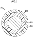
- FIG.2 is a cross sectional view showing a conventional insulated wire taken perpendicular to the longitudinal direction thereof.
- An insulated wire 200 having a conventional structure has a conductor 210, an insulation layer 220 arranged around the conductor 210, and a flame-retardant layer 230 arranged around the insulation layer 220 and containing a flame retardant.
- an additive having (some) flame retardancy e.g., an inorganic filler such as calcium carbonate or clay
- an additive having (some) flame retardancy e.g., an inorganic filler such as calcium carbonate or clay
- a polymer composition constituting the insulation layer 220 so that the insulation layer 220 per se can have some flame retardancy.
- the insulating properties of the polymer composition constituting the insulation layer 220 is lower than the insulating properties of a base polymer used to form the polymer composition.
- a base polymer of the polymer composition constituting the insulation layer 220 is, e.g., polyethylene
- a volume resistivity of the base polymer is, e.g., of the order of about 1x10 16 ⁇ cm.
- a flame-retardant additive, etc. is then mixed to the polymer composition, and this reduces a volume resistivity of the polymer composition constituting the insulation layer 220 down to the order of about 1x10 1 4 ⁇ cm.
- the inventors examined if the thinner flame-retardant layer 230 can be provided to reduce a diameter of the insulated wire 200. However, only by reducing the thickness of the flame-retardant layer 230 (without changing the thickness of the insulation layer 220 ), the insulated wire 200 cannot have high flame retardancy.
- the thinner insulation layer 220 can be provided.
- the insulated wire 200 cannot have high insulating properties. Therefore, it was examined if the amount of a flame-retardant additive, etc., mixed to the insulation layer 220 can be reduced so that the insulating properties of the polymer composition constituting the insulation layer 220 are increased closer to high insulating properties of the base polymer.
- the insulation layer 220 cannot have sufficient flame retardancy.
- the inventors conceived a new structure in which the insulation layer 220 is divided into a flame-retardant layer containing a flame-retardant additive and arranged on the inner side (on the conductor side) and an insulation layer containing a reduced amount of flame-retardant additive, etc., and arranged on the outer side (on the opposite side to the conductor).
- the insulation layer containing a reduced amount of flame-retardant additive, etc. is referred to as "high-electrical insulating layer”.
- the flame-retardant layer arranged on the inner side of the high-electrical insulating layer is referred to as “inner flame-retardant layer” and a flame-retardant layer arranged on the outer side of high-electrical insulating layer is referred to as “outer flame-retardant layer”.
- the high-electrical insulating layer is formed of a polymer composition of which insulating properties is enhanced (a decrease in insulating properties is suppressed) by reducing the mixed amount of flame-retardant additive, etc.
- the thickness of the high-electrical insulating layer required to obtain desired insulating properties can be reduced.
- the thickness of the easily combustible high-electrical insulating layer can be reduced, it is possible to reduce the thicknesses of the inner flame-retardant layer and the outer flame-retardant layer, i.e., to reduce the thickness of the combined flame-retardant layer.
- the volume resistivity of the polymer composition constituting the high-electrical insulating layer can be significantly increased to, e.g., about 100 times higher than the volume resistivity of the polymer composition originally used to form the insulation layer 220.
- reducing the thickness of the insulation layer by increasing the volume resistivity while achieving desired insulating properties is easier way than reducing the thickness of the flame-retardant layer.
- conductors have a twisted wire structure formed by twisting strands and thus have bumps and recesses on a surface thereof. If the high-electrical insulating layer is arranged directly on the conductor, the high-electrical insulating layer is likely to be broken due to electric field concentration caused by the bumps and recesses on the surface of the conductor and the thickness of the high-electrical insulating layer thus should not be reduced. Since the inner flame-retardant layer, which is arranged directly on the conductor and covers the bumps and recesses, serves as a bump-and-recess smoothing layer, the high-electrical insulating layer which is arranged on the inner flame-retardant layer can have a reduced thickness.
- the wire structure which allows for diameter reduction while achieving high insulating properties and high flame retardancy, is thus obtained.
- Such wire structure is preferably applied to, e.g., a thin insulated wire which has an outer diameter (a cross-sectional diameter) of not more than 3 mm.
- the insulating properties of insulated wire are evaluated by, e.g., a DC stability test which is described later. Flame retardancy of insulated wire is evaluated by, e.g., VFT or VTFT which are also described later.
- the intended use of the insulated wire is not specifically limited and is, e.g., for rolling stocks, vehicles or medical application.
- FIG.1 is a cross sectional view showing an example of the structure of the insulated wire 100 taken perpendicular to the longitudinal direction thereof.
- the insulated wire 100 has a conductor 110 and a cover layer 120 arranged around the conductor 110.
- the conductor 110 used here can be, e.g., a twisted wire formed by twisting plural strands (metal wires).
- the strand can be, e.g., a copper wire, a copper alloy wire, an aluminum wire, a gold wire or a silver wire, etc., or may be a wire of which outer surface is plated with a metal such as tin or nickel.
- the outer diameter (the cross-sectional diameter) of the conductor 110 is, e.g., not less than 0.70 mm and not more than 1.70 mm.
- the outer diameter (the cross-sectional diameter) of the strand is, e.g., not less than 0.10 mm and not more than 0.30 mm.
- the material, structure and size, etc., of the conductor 110 can be appropriately selected according to the characteristics required for the conductor 110 of the insulated wire 100.
- the cover layer 120 has a laminated structure 150 composed of an inner flame-retardant layer 131 arranged around the conductor 110, a high-electrical insulating layer 140 arranged around the inner flame-retardant layer 131, and an outer flame-retardant layer 132 arranged around the high-electrical insulating layer 140.
- the combined flame-retardant layer 130 is composed of the inner flame-retardant layer 131 and the outer flame-retardant layer 132.
- the inner flame-retardant layer 131 i.e., a flame-retardant layer 131 arranged on the inner side (on the conductor 110 side) of the high-electrical insulating layer 140, is formed of a polymer composition (A) containing a flame retardant.
- the inner flame-retardant layer 131 is formed by, e.g., extruding the polymer composition (A) on the outer surface of the conductor 110.
- a base polymer of the polymer composition (A) is e.g. a polyolefin resin.
- the polyolefin resin used here can be, e.g., a polyethylene-based resin, etc.
- the polyethylene-based resin used here include polyethylene such as low-density polyethylene (LDPE), linear low-density polyethylene (LLDPE) and high-density polyethylene (HDPE), ethylene-vinyl acetate copolymer (EVA), ethylene-ethyl acrylate copolymer, ethylene-methyl acrylate copolymer and ethylene-glycidyl methacrylate copolymer, etc.
- LDPE low-density polyethylene
- LLDPE linear low-density polyethylene
- HDPE high-density polyethylene
- EVA ethylene-vinyl acetate copolymer
- EVA ethylene-ethyl acrylate copolymer
- the base polymer of the polymer composition (A) preferably contains, e.g., EVA.
- EVA is preferable since its relatively high filler acceptability allows a flame retardant to be added easily and the resin per se has some flame retardancy.
- the flame retardant added to the polymer composition (A) is preferably a halogen-free flame retardant since it does not produce toxic gas, and for example, a metal hydroxide can be preferably used.
- a metal hydroxide it is possible to use, e.g., magnesium hydroxide, aluminum hydroxide, calcium hydroxide and these metal hydroxides with dissolved nickel. These flame retardants may be used alone or in a combination of two or more.
- the flame retardant is preferably surface-treated with, e.g., a silane coupling agent, a titanate-based coupling agent, fatty acid such as stearic acid, fatty acid salt such as stearate, or fatty acid metal such as calcium stearate to control mechanical characteristics (a balance between tensile strength and elongation) of the inner flame-retardant layer 131.
- the amount of the flame retardant to be mixed is preferably, e.g., not less than 100 parts by mass and not more than 250 parts by mass with respect to 100 parts by mass of the base polymer. When the mixed amount is less than 100 parts by mass, desired high flame retardancy may not be obtained. When the mixed amount is more than 250 parts by mass, mechanical characteristics of the inner flame-retardant layer 131 may decrease, resulting in a decrease in elongation percentage.
- the inner flame-retardant layer 131 is preferably formed of the cross-linked polymer composition (A) to improve flame retardancy and heat resistance.
- the crosslinking method can be, e.g., radiation crosslinking, chemical crosslinking or silane crosslinking, etc.
- the polymer composition (A) may contain a crosslinking aid or a cross-linking agent so as to be well cross-linked.
- radiation crosslinking is preferable to cross-link the high-electrical insulating layer 140 as described later, it is efficient to cross-link the inner flame-retardant layer 131 by radiation crosslinking at the same time as radiation crosslinking of the high-electrical insulating layer 140, i.e., in the same process as radiation crosslinking of the high-electrical insulating layer 140.
- the inner flame-retardant layer 131 is, e.g., an electrical insulating layer formed of the polymer composition (A) with a volume resistivity of about 1x10 14 ⁇ cm (or more).
- the volume resistivity of the polymer composition (A) is defined as the volume resistivity of the cross-linked polymer composition (A).
- the polymer composition (A) may contain, if required, other additives, e.g., carbon fiber, talc and clay, etc., as long as the characteristics of the inner flame-retardant layer 131 are not impaired.
- other additives e.g., carbon fiber, talc and clay, etc.
- the high-electrical insulating layer 140 is formed of a polymer composition (B) having a volume resistivity of not less than 1x10 16 ⁇ cm.
- the high-electrical insulating layer 140 is formed by, e.g., extruding the polymer composition (B) on the outer surface of the inner flame-retardant layer 131.
- a base polymer of the polymer composition (B) is a polymer having a volume resistivity of not less than 1x10 16 ⁇ cm, e.g., polyolefin resin, etc.
- the polyolefin resin used here can be, e.g., polyethylene such as LDPE, LLDPE or HDPE. These polyolefin resins may be used alone or in combination of two or more.
- the base polymer of the polymer composition (B) preferably contains, e.g., polyethylene.
- Polyethylene is preferable since its volume resistivity can be improved by cross-linking.
- the polyethylene used here may be any of LDPE, LLDPE and HDPE. LDPE may be used since it is easily cross-linked.
- the high-electrical insulating layer 140 is preferably formed of the cross-linked polymer composition (B) to improve the volume resistivity
- the crosslinking method can be, e.g., radiation crosslinking, chemical crosslinking or silane crosslinking, etc.
- the polymer composition (B) may contain a crosslinking aid or a cross-linking agent so as to be well cross-linked. Particularly, radiation crosslinking not requiring addition of additives is preferable to prevent a decrease in electrical insulating properties.
- the volume resistivity of the polymer composition (B) means the volume resistivity of the cross-linked polymer composition (B).
- the polymer composition (B) contain as little additives as possible to suppress as decrease in the volume resistivity, but if required, various additives may be contained a long as the volume resistivity of not less than 1x10 16 ⁇ cm can be maintained.
- the additives include antioxidant and copper inhibitor, etc.
- the polymer composition (B) do not contain, e.g., inorganic filler such as calcium carbonate, clay, talc, silica, wollastonite, zeolite, diatomaceous earth, silica sand, pumice powder, slate powder, alumina, aluminum sulfate, barium sulfate, lithopone, calcium sulfate and molybdenum disulfide, or flame retardant such as metal hydroxide to prevent a decrease in volume resistivity of the polymer composition (B).
- inorganic filler such as calcium carbonate, clay, talc, silica, wollastonite, zeolite, diatomaceous earth, silica sand, pumice powder, slate powder, alumina, aluminum sulfate, barium sulfate, lithopone, calcium sulfate and molybdenum disulfide, or flame retardant such as metal hydroxide to prevent a decrease in volume resistivity of the poly
- the outer flame-retardant layer 132 i.e., a flame-retardant layer 132 arranged on the outer side (on the opposite side to the conductor 110 ) of the high-electrical insulating layer 140, is formed of a polymer composition (C) containing a flame retardant.
- the outer flame-retardant layer 132 is formed by, e.g., extruding the polymer composition (C) on the outer surface of the high-electrical insulating layer 140.
- a base polymer of the polymer composition (C) is, e.g., the same as the base polymer of the polymer composition (A) constituting the inner flame-retardant layer 131, and is preferably, e.g., a polymer containing EVA.
- the base polymer of the polymer composition (C) constituting the outer flame-retardant layer 132 may be the same as or different from the base polymer of the polymer composition (A) constituting the inner flame-retardant layer 131.
- the flame retardant added to the polymer composition (C) is, e.g., the same as that added to the polymer composition (A) constituting the inner flame-retardant layer 131, and is preferably, e.g., a metal hydroxide.
- the amount of the flame retardant to be mixed can be, e.g., the same as the amount of the flame retardant to be mixed to the polymer composition (A) constituting the inner flame-retardant layer 131.
- the flame retardant added to the polymer composition (C) constituting the outer flame-retardant layer 132 may be the same as or different from the flame retardant added to the polymer composition (A) constituting the inner flame-retardant layer 131.
- the amount of the flame retardant mixed in the polymer composition (C) may be the same as or different from that in the polymer composition (A).
- the outer flame-retardant layer 132 is preferably formed of the cross-linked polymer composition (C) to improve flame retardancy and heat resistance.
- the crosslinking method can be, e.g., radiation crosslinking, chemical crosslinking or silane crosslinking, etc.
- the polymer composition (C) may contain a crosslinking aid or a cross-linking agent so as to be well cross-linked.
- radiation crosslinking is preferable to cross-link the high-electrical insulating layer 140, it is efficient to cross-link the outer flame-retardant layer 132 by radiation crosslinking at the same time as radiation crosslinking of the high-electrical insulating layer 140, i.e., in the same process as radiation crosslinking of the high-electrical insulating layer 140.
- the outer flame-retardant layer 132 is, e.g., an electrical insulating layer formed of the polymer composition (C) with a volume resistivity of about 1x10 14 ⁇ cm (or more).
- the volume resistivity of the polymer composition (C) means the volume resistivity of the cross-linked polymer composition (C).
- the polymer composition (C) may contain, if required, other additives, e.g., carbon fiber, talc and clay, etc., as long as the characteristics of the outer flame-retardant layer 132 are not impaired.
- the laminated structure 150 of the cover layer 120 composed of the inner flame-retardant layer 131, the high-electrical insulating layer 140 and the outer flame-retardant layer 132 will be further described.
- the high-electrical insulating layer 140 is configured to receive preferably not less than 80%, more preferably not less than 90%, further preferably not less than 95%, of voltage applied in the thickness direction of the laminated structure 150.
- each of the inner flame-retardant layer 131 and the outer flame-retardant layer 132 can be reduced accordingly.
- insulation breakdown is more likely to occur than in the high-electrical insulating layer 140.
- High insulating properties of the insulated wire 100 can be achieved by reducing voltage applied to the inner flame-retardant layer 131 and the outer flame-retardant layer 132.
- the high-electrical insulating layer 140 is formed thinner than at least one of the inner flame-retardant layer 131 and the outer flame-retardant layer 132.
- the thickness of the combined flame-retardant layer 130 (the inner flame-retardant layer 131 and the outer flame-retardant layer 132 ) can be also reduced.
- the volume resistivity of the polymer composition (B) constituting the high-electrical insulating layer 140 is preferably at least not less than 1x10 16 ⁇ cm, more preferably not less than 1x10 17 ⁇ cm.
- the upper limit of the volume resistivity of the polymer composition (B) is not specifically limited.
- the volume resistivity of the polymer composition (B) constituting the high-electrical insulating layer 140 is preferably not less than 10 times, more preferably not less than 50 times, further preferably not less than 100 times the volume resistivity of the polymer composition (A) constituting the inner flame-retardant layer 131 and that of the polymer composition (C) constituting the outer flame-retardant layer 132.
- the thickness of the high-electrical insulating layer 140 is more preferably not more than half the thickness of the combined flame-retardant layer 130 (the sum of the thickness of the inner flame-retardant layer 131 and the thickness of the outer flame-retardant layer 132 ), further preferably not more than half of at least one of the thickness of the inner flame-retardant layer 131 and the thickness of the outer flame-retardant layer 132.
- the outer diameter (the cross-sectional diameter) of the insulated wire 100 is preferably not more than 3 mm, more preferably not more than 2.5 mm.
- the rated (AC) voltage of the insulated wire 100 is, e.g., not more than 660V ( 600V , as an example). Having a small diameter is also advantageous in that it is easy to simultaneously cross-link the inner flame-retardant layer 131, the high-electrical insulating layer 140 and the outer flame-retardant layer 132 by radiation crosslinking.
- the upper limit of the thickness of the high-electrical insulating layer 140 is, e.g., preferably not more than 0.2 mm, more preferably not more than 0.15 mm.
- the lower limit of the thickness of the high-electrical insulating layer 140 is not specifically limited as long as desired insulating properties are obtained, but not less than 0.05 mm is preferable so that, for example, the high-electrical insulating layer 140 can have a highly uniform thickness and resulting stable insulating properties can be obtained.
- the combined flame-retardant layer 130 is formed to have a well-balanced, sufficiently large thickness which can prevent the high-electrical insulating layer 140 from burning.
- the respective thicknesses of the inner flame-retardant layer 131 and the outer flame-retardant layer 132 can be appropriately changed, if required, in a well-balanced manner so that the combined flame-retardant layer 130 can have a sufficient thickness.
- the outer flame-retardant layer 132 can be thicker than the inner flame-retardant layer 131, the inner flame-retardant layer 131 can be thicker than the outer flame-retardant layer 132, or, the inner flame-retardant layer 131 and the outer flame-retardant layer 132 can have the same thickness.
- the outer flame-retardant layer 132 is preferably thicker than the inner flame-retardant layer 131.
- the thickness of the combined flame-retardant layer 130 is preferably, e.g., not less than double the high-electrical insulating layer 140.
- the upper limit of the thickness of the combined flame-retardant layer 130 is, e.g., preferably not more than 0.4 mm.
- the lower limit of the thickness of the combined flame-retardant layer 130 is not specifically limited as long as it is determined according to the thickness of the high-electrical insulating layer 140 and the flame retardancy can be obtained, but not less than 0.2 mm is preferable to obtain, e.g., stable flame retardancy.
- the inner flame-retardant layer 131 is arranged directly on the conductor 110 (in contact with the conductor 110 ) and covers the bumps and recesses on the surface of the conductor 110, thereby serving as a bump-and-recess smoothing layer to prevent electric field concentration.
- the high-electrical insulating layer 140 which is arranged on the inner flame-retardant layer 131 can have a reduced thickness.
- the thickness of the inner flame-retardant layer 131 here is expressed as a thickness on the bumps of the twist on the surface of the conductor 110 (a thickness of the thinnest portion), i.e., a thickness from the outer diameter of the conductor 110.
- the upper limit of the thickness of the inner flame-retardant layer 131 can be appropriately selected within the thickness range of the combined flame-retardant layer 130, and is not specifically limited.
- the lower limit of the thickness of the inner flame-retardant layer 131 is not specifically limited, but is preferably not less than 0.05 mm so that, for example, the bumps and recesses on the surface of the conductor 110 are sufficiently covered, and also, the inner flame-retardant layer 131 can have a highly uniform thickness and resulting stable flame retardancy can be obtained.
- the upper limit of the thickness of the outer flame-retardant layer 132 can be appropriately selected within the thickness range of the combined flame-retardant layer 130, and is not specifically limited. Meanwhile, the lower limit of the thickness of the outer flame-retardant layer 132 is not specifically limited, but is preferably not less than 0.05 mm so that, for example, the outer flame-retardant layer 132 can have a highly uniform thickness and resulting stable flame retardancy can be obtained.
- another layer is not arranged between the inner flame-retardant layer 131 and the high-electrical insulating layer 140.
- the high-electrical insulating layer 140 is preferably arranged directly on the inner flame-retardant layer 131 (in contact with the inner flame-retardant layer 131 ).
- another layer is not arranged between the high-electrical insulating layer 140 and the outer flame-retardant layer 132.
- the outer flame-retardant layer 132 is preferably arranged directly on the high-electrical insulating layer 140 (in contact with the high-electrical insulating layer 140 ).
- another layer is not arranged around the outer flame-retardant layer 132.
- the outer flame-retardant layer 132 be the outermost layer of the cover layer 120, i.e., the outermost layer of the insulated wire 100.
- the inner flame-retardant layer 131, the high-electrical insulating layer 140 and the outer flame-retardant layer 132 are preferably simultaneously extruded on the conductor 110.
- air dust to be a cause of electric field concentration can be prevented from attaching to a boundary surface between the inner flame-retardant layer 131 and the high-electrical insulating layer 140 and to a boundary surface between the high-electrical insulating layer 140 and the outer flame-retardant layer 132.
- the inner flame-retardant layer 131 may have, if required, a laminated structure composed of plural flame-retardant layers (sub-flame-retardant layers).
- the high-electrical insulating layer 140 may have, if required, a laminated structure composed of plural insulating layers (sub-insulating layers).
- the outer flame-retardant layer 132 may have, if required, a laminated structure composed of plural flame-retardant layers (sub-flame-retardant layers).
- the first embodiment it is possible to reduce a diameter of the insulated wire while achieving high insulating properties and high flame retardancy.
- the insulated wire in the first embodiment can be used alone, and also can be used, if required, in combination with another member, e.g., used as a core of a cable.
- Insulated wires in Examples 1, 2 and Comparative Examples 1 to 4 were made as follows.
- the polymer composition (A) for forming an inner flame-retardant layer, the polymer composition (B) for forming a high-electrical insulating layer and the polymer composition (C) for forming an outer flame-retardant layer were prepared.
- the same polymer composition was prepared as the polymer composition (A) for forming an inner flame-retardant layer and the polymer composition (C) for forming an outer flame-retardant layer.
- As the polymer composition (B) for forming a high-electrical insulating layer three types of polymer compositions (compositions 1 to 3 ) with various volume resistivities were prepared according to the different volume resistivities of the high-electrical insulating layers of the respective samples.
- the mixing proportions for the polymer compositions (A) and (C) are shown in Table 1, and the mixing proportions for the polymer compositions (B) are shown in Table 2.
- Table 1 Polymer compositions (A) and (C) for forming Inner and Outer flame-retardant layers Base polymer EVA 85 Acid-modified polyolefin resin 15 Flame retardant Magnesium hydroxide 200 Colorant FT carbon 2 Lubricant Zinc stearate 1 Parts by mass Table 2 Polymer composition (B) for forming High-electrical insulating layer Composition 1 (Example 1) Composition 2 (Example 2) Composition 3 (Comparative Example 1 to 4) Base polymer High-density polyethylene 100 - - Linear low-density polyethylene - 100 100 Inorganic filler Clay - - 100 Volume resistivity ( ⁇ cm) 1.34E+17 9.48E+16 1.60E+15 Parts by mass
- Conductors having an outer diameter of 1.23 mm were prepared.
- the polymer compositions (A), (B) and (C) were simultaneously extruded on each of the conductors and were cross-linked by electron beam irradiation, thereby forming the inner flame-retardant layer, the high-electrical insulating layer and the outer flame-retardant layer.
- the high-electrical insulating layers of the insulated wires in Examples 1, 2 and Comparative Examples 1 to 4 had different volume resistivities, i.e., were formed of the polymer compositions (B) with different mixing proportions. Also, the outer flame-retardant layer and the high-electrical insulating layer were formed in various thicknesses. The volume resistivity was the same between the inner flame-retardant layer and the outer flame-retardant layer, and was fixed for all of Examples 1, 2 and Comparative Examples 1 to 4. The thickness of the inner flame-retardant layer was also fixed.
- Table 3 shows the configuration of the insulated wires of Examples 1, 2 and Comparative Examples 1 to 4; volume resistivity of the polymer composition used to form the flame-retardant layer (volume resistivity of the flame-retardant layer), volume resistivity of the polymer composition used to form the high-electrical insulating layer (volume resistivity of the high-electrical insulating layer), thickness of the high-electrical insulating layer, thickness of the inner flame-retardant layer and thickness of the outer flame-retardant layer.
- Table 3 also shows a voltage sharing rate in the laminated structure composed of the inner flame-retardant layer, the high-electrical insulating layer and the outer flame-retardant layer, i.e., a ratio of resistance of the high-electrical insulating layer to the sum of resistance of the inner flame-retardant layer, resistance of the high-electrical insulating layer and resistance of the outer flame-retardant layer, in the thickness direction of the laminated structure.
- Insulating properties (electrical characteristics) and flame retardancy of the insulated wires in Examples 1, 2 and Comparative Examples 1 to 4 were evaluated as follows. Table 3 shows the evaluation results.
- VFT vertical flame test
- VTFT vertical tray flame test
- VFT was conducted in accordance with the Test for vertical flame propagation for a single insulated wire or cable specified by EN 60332-1-2.
- 600 mm-long insulated wires were held vertical and a flame was applied thereto for 60 seconds.
- the wires passed the test ( ⁇ : excellent) when the fire was extinguished within 30 seconds after removing the flame, the wires passed the test ( ⁇ : acceptable) when the fire was extinguished within 60 seconds, and the wires failed the test ( ⁇ ) when the fire was not extinguished within 60 seconds.
- VTFT was conducted in accordance with the Test for vertical flame spread of vertically mounted bunched wires (Flame propagation in bunched cables) specified by EN 50266-2-4.
- seven 3.5- meter insulated wires were twisted into one bundle, and eleven bundles were vertically arranged at equal intervals and were burnt for 20 minutes. Then, a char length from the lower end after self-extinction was measured.
- the wires with a char length of not more than 1.5 m were regarded as "Pass ( ⁇ : excellent)", those with a char length of not more than 2.5 m were regarded as "Pass ( ⁇ : acceptable)", and those with a char length of more than 2.5 m were regarded as "Fail ( ⁇ )".
- the volume resistivity of the flame-retardant layer was 4x10 14 ⁇ cm in both Examples 1 and 2
- the volume resistivity of the high-electrical insulating layer was 1.34x10 17 ⁇ cm in Example 1 and 9.48x10 16 ⁇ cm in Example 2
- the voltage sharing rate of the high-electrical insulating layer 140 was 98.9% in Example 1 and 99.1 % in Example 2.
- the thickness of the inner flame-retardant layer was 0.1 mm in both Examples 1 and 2
- the thickness of the outer flame-retardant layer was 0.3 mm in both Examples 1 and 2.
- the thickness of the high-electrical insulating layer was 0.11 mm in Example 1 and 0.18 mm in Example 2.
- the insulated wires in Examples 1 and 2 passed both the electrical characteristic and flame retardant tests since the volume resistivity of the high-electrical insulating layer was not less than 1x10 16 ⁇ cm, the voltage sharing rate of the high-electrical insulating layer was not less than 80 %, and furthermore, the high-electrical insulating layer was thinner than at least one of the inner flame-retardant layer and the outer flame-retardant layer.
- the voltage sharing rate of the high-electrical insulating layer not only just satisfied the condition of not less than 80 %, but also achieved the conditions of not less than 90 % and not less than 95 %.
- the thickness of the combined flame-retardant layer (the inner flame-retardant layer and the outer flame-retardant layer) was 0.4 mm in both Examples 1 and 2, and the thickness of the high-electrical insulating layer was not more than half the thickness of the combined flame-retardant layer (specifically, not more than 0.2 mm) in both Examples 1 and 2.
- Example 1 since the thickness of the high-electrical insulating layer was not more than half of at least one of the thickness of the inner flame-retardant layer and the thickness of the outer flame-retardant layer (more specifically, not more than 0.15 mm), higher flame retardancy and smaller diameter than Example 2 were obtained.
- Example 1 since the volume resistivity of the high-electrical insulating layer was not less than 1x10 17 ⁇ cm, it was possible to obtain the thinner high-electrical insulating layer than Example 2.
- a ratio of the volume resistivity of the high-electrical insulating layer to the volume resistivity of the flame-retardant layer was 335 times in Example 1 and 237 times in Example 2, and the conditions of 10 times, not less than 50 times, and not less than 100 times were satisfied in both Examples 1 and 2.
- the volume resistivity of the flame-retardant layer was 4x10 14 ⁇ cm in both Comparative Examples 1 and 2, the volume resistivity of the high-electrical insulating layer was 1.60x10 15 ⁇ cm in both Comparative Examples 1 and 2.
- the voltage sharing rate of the high-electrical insulating layer 140 was 52.4 % in Comparative Example 1 and 66.7 % in Comparative Example 2.
- the thickness of the inner flame-retardant layer was 0.1 mm in both Comparative Examples 1 and 2, and the thickness of the outer flame-retardant layer was 0.3 mm in both Comparative Examples 1 and 2.
- the thickness of the high-electrical insulating layer was 0.11 mm in Comparative Example 1 and 0.2 mm in Comparative Example 2.
- the insulated wires in Comparative Examples 1 and 2 failed the electrical characteristic test since the volume resistivity of the high-electrical insulating layer was less than 1x10 16 ⁇ cm and the voltage sharing rate of the high-electrical insulating layer was less than 80 %.
- the samples passed the flame retardant test since the high-electrical insulating layer was thinner than at least one of the inner flame-retardant layer and the outer flame-retardant layer. Meanwhile, the ratio of the volume resistivity of the high-electrical insulating layer to the volume resistivity of the flame-retardant layer was 4 times in both Comparative Examples 1 and 2, which is less than 10 times.
- the volume resistivity of the flame-retardant layer was 4x10 14 ⁇ cm in both Comparative Examples 3 and 4, the volume resistivity of the high-electrical insulating layer was 1.60x10 15 ⁇ cm in both Comparative Examples 3 and 4.
- the voltage sharing rate of the high-electrical insulating layer 140 was 68.8% in Comparative Example 3 and 74.2% in Comparative Example 4.
- the thickness of the inner flame-retardant layer was 0.1 mm in both Comparative Examples 3 and 4, and the thickness of the outer flame-retardant layer was 0.1 mm in Comparative Example 3 and 0.15 mm in Comparative Example 4.
- the thickness of the high-electrical insulating layer was 0.11 mm in Comparative Example 3 and 0.18 mm in Comparative Example 4.
- the insulated wires in Comparative Examples 3 and 4 failed electrical characteristic test since the volume resistivity of the high-electrical insulating layer was less than 1x10 16 ⁇ cm and the voltage sharing rate of the high-electrical insulating layer was less than 80 %. Furthermore, the samples also failed the flame retardant test since the high-electrical insulating layer was thicker than both the inner flame-retardant layer and the outer flame-retardant layer. Meanwhile, the ratio of the volume resistivity of the high-electrical insulating layer to the volume resistivity of the flame-retardant layer was 4 times in both Comparative Examples 3 and 4, which is less than 10 times.
- the inventors studied the insulated wire structure which allows a diameter to be reduced while achieving high insulating properties and high flame retardancy.
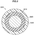
- FIG.5 is a cross sectional view showing a conventional insulated wire taken perpendicular to the longitudinal direction thereof.
- a insulated wire 2200 having a conventional structure has a conductor 2210, an insulation layer 2220 arranged around the conductor 2210, and a flame-retardant layer 2230 arranged around the insulation layer 2220 and containing a flame retardant.
- an additive having (some) flame retardancy e.g., an inorganic filler such as calcium carbonate or clay
- an additive having (some) flame retardancy e.g., an inorganic filler such as calcium carbonate or clay
- a polymer composition constituting the insulation layer 2220 so that the insulation layer 2220 per se has some flame retardancy.
- the insulating properties of the polymer composition constituting the insulation layer 2220 is lower than the insulating properties of a base polymer used to form the polymer composition.
- a base polymer of the polymer composition constituting the insulation layer 2220 is, e.g., polyethylene
- a volume resistivity of the base polymer is, e.g., of the order of about 1x10 16 ⁇ cm.
- a flame-retardant additive, etc. is then mixed to the polymer composition, and this reduces a volume resistivity of the polymer composition constituting the insulation layer 2220 down to the order of about 1x10 14 ⁇ cm.
- the inventors examined if the thinner flame-retardant layer 2230 can be provided to reduce a diameter of the insulated wire 2200. However, only by reducing the thickness of the flame-retardant layer 2230 (without changing the thickness of the insulation layer 2220 ), the insulated wire 2200 cannot have high flame retardancy.
- the thinner insulation layer 2220 can be provided.
- the insulated wire 2200 cannot have high insulating properties. Therefore, it was examined if the amount of a flame-retardant additive, etc., mixed to the insulation layer 2220 can be reduced so that the insulating properties of the polymer composition constituting the insulation layer 2220 can be increased closer to high insulating properties of the base polymer to allow the thickness of the insulation layer 2220 required to obtain desired insulating properties to be reduced.
- the conductor 2210 has a twisted wire structure formed by twisting strands and thus has bumps and recesses on a surface thereof. Therefore, insulation breakdown is likely to occur in the insulation layer 2220 due to electric field concentration caused by the bumps and recesses on the surface of the conductor 2210, and the insulation layer 2220 needs to be thick to some extent to improve voltage-resistant characteristics. Thus, the thickness of the insulation layer 2220 should not be simply reduced.
- the inventors conceived a new structure using an insulation layer containing a reduced amount of flame-retardant additive, etc., and a semiconducting layer containing a conductive agent and arranged directly on the conductor at the same time on the inner side (on the conductor side) of such insulation layer.
- the insulation layer containing a reduced amount of flame-retardant additive, etc. is referred to as "high-electrical insulating layer”.
- the thickness of the high-electrical insulating layer required to obtain desired insulating properties can be reduced.
- the semiconducting layer which covers the bumps and recesses on the conductor surface serves as a bump-and-recess smoothing layer
- the high-electrical insulating layer which is arranged on the semiconducting layer can have a reduced thickness.
- the thickness of the easily combustible high-electrical insulating layer can be reduced, the thicknesses of the flame-retardant layer required to obtain desired flame retardancy can be also reduced.
- the volume resistivity of the polymer composition constituting the high-electrical insulating layer can be significantly increased to, e.g., about 100 times higher than the volume resistivity of the polymer composition originally used to form the insulation layer 2220.
- reducing the thickness of the insulation layer by increasing the volume resistivity while achieving desired insulating properties is easier way than reducing the thickness of the flame-retardant layer.
- the wire structure which allows for diameter reduction while achieving high insulating properties and high flame retardancy, is thus obtained.
- Such wire structure is preferably applied to, e.g., a thin insulated wire which has an outer diameter (a cross-sectional diameter) of not more than 7 mm.
- the insulating properties of insulated wire are evaluated by, e.g., a DC stability test which is described later. Flame retardancy of insulated wire is evaluated by, e.g., VFT or VTFT which are also described later.
- the intended use of the insulated wire is not specifically limited and is, e.g., for rolling stocks, vehicles or medical application.
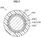
- FIG.3 is a cross sectional view showing an example of the structure of the insulated wire 2100 taken perpendicular to the longitudinal direction thereof.
- the insulated wire 2100 has a conductor 2110 and a cover layer 2120 arranged around the conductor 2110.
- the conductor 2110 used here can be, e.g., a twisted wire formed by twisting plural strands (metal wires).
- the strand can be, e.g., a copper wire, a copper alloy wire, an aluminum wire, a gold wire or a silver wire, etc., or may be a wire of which outer surface is plated with a metal such as tin or nickel.
- the outer diameter (the cross-sectional diameter) of the conductor 2110 is, e.g., not less than 1 mm and not more than 6 mm.
- the outer diameter (the cross-sectional diameter) of the strand is, e.g., not less than 0.1 mm and not more than 0.5 mm.
- the material, structure and size, etc., of the conductor 2110 can be appropriately selected according to the characteristics required for the conductor 2110 of the insulated wire 2100.
- the cover layer 2120 has a laminated structure 2160 composed of a semiconducting layer 2130 arranged around the conductor 2110, a high-electrical insulating layer 2140 arranged around the semiconducting layer 2130, and a flame-retardant layer 2150 arranged around the high-electrical insulating layer 2140.
- the semiconducting layer 2130 is formed of a polymer composition (A) containing a conductive agent and having a volume resistivity of not more than 1x10 9 ⁇ cm.
- the semiconducting layer 2130 is formed by, e.g., extruding the polymer composition (A) on the outer surface of the conductor 2110.
- a base polymer of the polymer composition (A) is, e.g., a polyolefin resin, etc.
- the polyolefin resin used here can be, e.g., a polyethylene-based resin, etc.
- the polyethylene-based resin used here include polyethylene such as low-density polyethylene (LDPE), linear low-density polyethylene (LLDPE), high-density polyethylene (HDPE), ethylene-vinyl acetate copolymer (EVA), ethylene-ethyl acrylate copolymer, ethylene-methyl acrylate copolymer, ethylene-glycidyl methacrylate copolymer, ethylene-butene copolymer, ethylene-butene hexene terpolymer, ethylene propylene diene terpolymer (EPDM), ethylene-octene copolymer (EOR), ethylene-propylene copolymer (EPR), ethylene-styrene
- the base polymer of the polymer composition (A) preferably contains, e.g., EVA.
- EVA is preferable since its relatively high filler acceptability allows a conductive agent to be added easily and the resin per se has some flame retardancy.
- the VA content of EVA is, e.g., preferably not less than 15 % in view of filler acceptability, and is, e.g., preferably not more than 80 % in view of manufacturability such as stickiness.
- Examples of the conductive agent mixed in the polymer composition (A) include carbon black and carbon nanotube, etc., and it is possible to suitably use, e.g., carbon black.
- Examples of the carbon black used here include furnace black, channel black, acetylene black and thermal black, etc., and acetylene black can be preferably used since high conductivity can be imparted with a small amount.
- These conductive agents may be used alone or in combination of two or more.
- the amount of conductive agent to be mixed is not specifically limited as long as the polymer composition (A) constituting the semiconducting layer 2130 has a volume resistivity of not more than 1x10 9 ⁇ cm.
- the amount of carbon black mixed per 100 parts by mass of the base polymer is not less than 30 parts by mass.
- the mixed amount of the conductive agent be not excessive since it causes a decrease in, e.g., mechanical characteristics of the semiconducting layer 2130 and a resulting decrease in elongation percentage.
- the amount of carbon black mixed per 100 parts by mass of the base polymer is not more than 150 parts by mass.
- the semiconducting layer 2130 is preferably formed of the cross-linked polymer composition (A) to improve heat resistance.
- the crosslinking method can be, e.g., radiation crosslinking, chemical crosslinking or silane crosslinking, etc.
- the polymer composition (A) may contain a crosslinking aid or a cross-linking agent so as to be well cross-linked. Since radiation crosslinking is preferable to cross-link the high-electrical insulating layer 2140 as described later, it is efficient to cross-link the semiconducting layer 2130 by radiation crosslinking at the same time as radiation crosslinking of the high-electrical insulating layer 2140, i.e., in the same process as radiation crosslinking of the high-electrical insulating layer 2140.
- the volume resistivity of the polymer composition (A) is defined as the volume resistivity of the cross-linked polymer composition (A).
- the polymer composition (A) may contain, if required, other additives, e.g., flame retardant, antioxidant, copper inhibitor, reinforcing agent and process oil, etc., as long as the characteristics of the semiconducting layer 2130 are not impaired.
- additives e.g., flame retardant, antioxidant, copper inhibitor, reinforcing agent and process oil, etc.
- the high-electrical insulating layer 2140 is formed of a polymer composition (B) having a volume resistivity of not less than 1x10 16 ⁇ cm.
- the high-electrical insulating layer 2140 is formed by, e.g., extruding the polymer composition (B) on the outer surface of the semiconducting layer 2130.
- a base polymer of the polymer composition (B) is a polymer having a volume resistivity of not less than 1x10 16 ⁇ cm, e.g., polyolefin resin, etc.
- the polyolefin resin used here can be, e.g., polyethylene such as LDPE, LLDPE or HDPE. These polyolefin resins may be used alone or in combination of two or more.
- the base polymer of the polymer composition (B) preferably contains, e.g., polyethylene.
- Polyethylene is preferable since its volume resistivity can be improved by cross-linking.
- the polyethylene used here may be any of LDPE, LLDPE and HDPE. LDPE may be used since it is easily cross-linked.
- the high-electrical insulating layer 2140 is preferably formed of the cross-linked polymer composition (B) to improve the volume resistivity
- the crosslinking method can be, e.g., radiation crosslinking, chemical crosslinking or silane crosslinking, etc.
- the polymer composition (B) may contain a crosslinking aid or a cross-linking agent so as to be well cross-linked. Particularly, radiation crosslinking not requiring addition of additives is preferable to prevent a decrease in electrical insulating properties.
- the volume resistivity of the polymer composition (B) means the volume resistivity of the cross-linked polymer composition (B).
- the polymer composition (B) contain as little additives as possible to suppress a decrease in the volume resistivity, but if required, various additives may be contained as long as the volume resistivity of not less than 1x10 16 ⁇ cm can be maintained.
- the additives include antioxidant and copper inhibitor, etc.
- the polymer composition (B) do not contain, e.g., inorganic filler such as calcium carbonate, clay, talc, silica, wollastonite, zeolite, diatomaceous earth, silica sand, pumice powder, slate powder, alumina, aluminum sulfate, barium sulfate, lithopone, calcium sulfate and molybdenum disulfide, or flame retardant such as metal hydroxide to prevent a decrease in volume resistivity of the polymer composition (B).
- inorganic filler such as calcium carbonate, clay, talc, silica, wollastonite, zeolite, diatomaceous earth, silica sand, pumice powder, slate powder, alumina, aluminum sulfate, barium sulfate, lithopone, calcium sulfate and molybdenum disulfide, or flame retardant such as metal hydroxide to prevent a decrease in volume resistivity of the poly
- the flame-retardant layer 2150 is formed of a polymer composition (C) containing a flame retardant.
- the flame-retardant layer 2150 is formed by, e.g., extruding the polymer composition (C) on the outer surface of the high-electrical insulating layer 2140.
- a base polymer of the polymer composition (C) is, e.g., a polyolefin resin, etc.
- the polyolefin resin used here can be, e.g., a polyethylene-based resin, etc.
- the polyethylene-based resin used here include polyethylene such as LDPE, LLDPE and HDPE, EVA, ethylene-ethyl acrylate copolymer, ethylene-methyl acrylate copolymer, ethylene-glycidyl methacrylate copolymer, ethylene-butene copolymer, ethylene-butene hexene terpolymer, ethylene propylene diene terpolymer (EPDM), ethylene-octene copolymer (EOR), ethylene-propylene copolymer (EPR), ethylene-styrene copolymer, styrene-butadiene copolymer, and these polymers modified with and acid such as maleic acid.
- the base polymer of the polymer composition (C) preferably contains, e.g., EVA.
- EVA is preferable since its relatively high filler acceptability allows a flame retardant to be added easily and the resin per se has some flame retardancy.
- the VA content of EVA is, e.g., preferably not less than 15 % in view of filler acceptability, and is, e.g., preferably not more than 60% to suppress a decrease in low-temperature performance.
- the flame retardant added to the polymer composition (C) is preferably a halogen-free flame retardant since it does not produce toxic gas, and for example, a metal hydroxide can be preferably used.
- a metal hydroxide it is possible to use, e.g., magnesium hydroxide, aluminum hydroxide, calcium hydroxide and these metal hydroxides with dissolved nickel. These flame retardants may be used alone or in a combination of two or more.
- the flame retardant is preferably surface-treated with, e.g., a silane coupling agent, a titanate-based coupling agent, fatty acid such as stearic acid, fatty acid salt such as stearate, or fatty acid metal such as calcium stearate to control mechanical characteristics (a balance between tensile strength and elongation) of the flame-retardant layer 2150.
- a silane coupling agent e.g., a titanate-based coupling agent
- fatty acid such as stearic acid
- fatty acid salt such as stearate
- fatty acid metal such as calcium stearate
- the amount of the flame retardant to be mixed is preferably, e.g., not less than 100 parts by mass and not more than 250 parts by mass with respect to 100 parts by mass of the base polymer.
- the mixed amount is less than 100 parts by mass, desired high flame retardancy may not be obtained.
- the mixed amount is more than 250 parts by mass, mechanical characteristics of the flame-retardant layer 2150 may decrease, resulting in a decrease in elongation percentage.
- the flame-retardant layer 2150 is preferably formed of the cross-linked polymer composition (C) to improve flame retardancy and heat resistance.
- the crosslinking method can be, e.g., radiation crosslinking, chemical crosslinking or silane crosslinking, etc.
- the polymer composition (C) may contain a crosslinking aid or a cross-linking agent so as to be well cross-linked.
- radiation crosslinking is preferable to cross-link the high-electrical insulating layer 2140, it is efficient to cross-link the flame-retardant layer 2150 by radiation crosslinking at the same time as radiation crosslinking of the high-electrical insulating layer 2140, i.e., in the same process as radiation crosslinking of the high-electrical insulating layer 2140.
- the flame-retardant layer 2150 is, e.g., an electrical insulating layer formed of the polymer composition (C) with a volume resistivity of about 1x10 14 ⁇ cm (not less than 1x10 13 ⁇ cm, or not less than 1x10 14 ⁇ cm).
- the volume resistivity of the polymer composition (C) means the volume resistivity of the cross-linked polymer composition (C).
- the polymer composition (C) may contain, if required, other additives, e.g., antioxidant, copper inhibitor, lubricant, inorganic filler, compatibilizing agent, stabilizer, carbon black and colorant, etc., as long as the characteristics of the flame-retardant layer 2150 are not impaired.
- additives e.g., antioxidant, copper inhibitor, lubricant, inorganic filler, compatibilizing agent, stabilizer, carbon black and colorant, etc.
- the laminated structure 2160 of the cover layer 2120 composed of the semiconducting layer 2130, the high-electrical insulating layer 2140 and the flame-retardant layer 2150 will be further described.
- the high-electrical insulating layer 2140 is formed thinner than the flame-retardant layer 2150. This reduces the thickness of the laminated structure 2160 and thus reduces the diameter of the insulated wire 2100, and at the same time, high flame retardancy is achieved since flammability of the laminated structure 2160 due to having the high-electrical insulating layer 2140 is reduced by the flame-retardant layer 2150.
- the volume resistivity of the polymer composition (B) constituting the high-electrical insulating layer 2140 is preferably not less than 1x10 16 ⁇ cm, more preferably not less than 1x10 17 ⁇ cm.
- the upper limit of the volume resistivity of the polymer composition (B) is not specifically limited.
- the thickness of the high-electrical insulating layer 2140 is more preferably not more than half the thickness of the flame-retardant layer 2150, further preferably not more than one-third of the thickness of the flame-retardant layer 2150.
- the semiconducting layer 2130 is arranged directly on the conductor 2110 (in contact with the conductor 2110 ) and covers the bumps and recesses on the surface of the conductor 2110, thereby serving as a bump-and-recess smoothing layer to prevent electric field concentration.
- the high-electrical insulating layer 2140 which is arranged on the semiconducting layer 2130 can have a reduced thickness.
- the volume resistivity of the polymer composition (A) constituting the semiconducting layer 2130 is preferably not more than 1x10 9 ⁇ cm. Meanwhile, the lower limit of the volume resistivity of the polymer composition (A) is not specifically limited.
- the semiconducting layer 2130 needs to cover the bumps and recesses on the surface of the conductor 2110 (needs to fill the recesses to provide a smooth surface), but the semiconducting layer 2130 can have a desired small thickness.
- the thickness of the semiconducting layer 2130 here is expressed as a thickness on the bumps of the twist on the surface of the conductor 2110 (a thickness of the thinnest portion), i.e., a thickness from the outer diameter of the conductor 2110.
- the thickness of the semiconducting layer 2130 is preferably smaller than the thickness of the flame-retardant layer 2150, more preferably not more than half the thickness of the flame-retardant layer 2150, and further preferably not more than one-third of the thickness of the flame-retardant layer 2150.
- the thickness of a laminated portion of the semiconducting layer 2130 and the high-electrical insulating layer 2140 i.e., the sum of the thickness of the semiconducting layer 2130 and the thickness of the high-electrical insulating layer 2140 is more preferably smaller than the thickness of the flame-retardant layer 2150, further preferably not more than two-third of the thickness of the flame-retardant layer 2150.
- the high-electrical insulating layer 2140 is configured to receive preferably not less than 80 %, more preferably not less than 90 %, further preferably not less than 95 %, of voltage applied in the thickness direction of a laminated portion of the high-electrical insulating layer 2140 and the flame-retardant layer 2150.
- voltage applied to the flame-retardant layer 2150 can be reduced accordingly.
- insulation breakdown is more likely to occur than in the high-electrical insulating layer 2140.
- High insulating properties of the insulated wire 2100 can be achieved by reducing voltage applied to the flame-retardant layer 2150.
- the volume resistivity of the polymer composition (B) constituting the high-electrical insulating layer 2140 is preferably not less than 1x10 16 ⁇ cm, more preferably not less than 1x10 17 ⁇ cm.
- the volume resistivity of the polymer composition (B) constituting the high-electrical insulating layer 2140 is preferably not less than 10 times, more preferably not less than 50 times, further preferably not less than 100 times the volume resistivity of the polymer composition (C) constituting the flame-retardant layer 2150.
- the outer diameter (the cross-sectional diameter) of the insulated wire 2100 is preferably not more than 7 mm.
- the rated (AC) voltage of the insulated wire 2100 is, e.g., not more than 3600 V. Having a small diameter is also advantageous in that it is easy to simultaneously cross-link semiconducting layer 2130, the high-electrical insulating layer 2140 and the flame-retardant layer 2150 by radiation crosslinking.
- the upper limit of the thickness of the semiconducting layer 2130 (on the bumps of the twist on the surface of the conductor 2110, the thickness of the thinnest portion) is preferably, e.g., not more than 0.10 mm.
- the lower limit of the thickness of the semiconducting layer 2130 is not specifically limited as long as the bumps and recesses on the surface of the conductor 2110 are covered, but not less than 0.05 mm is preferable so that, for example, the semiconducting layer 2130 can have a highly uniform thickness and resulting stable voltage-resistant characteristics can be obtained.
- the thickness of the portion located above the recesses of the twist on the surface of the conductor 2110 and filling the recesses is preferably not less than half the strand outer diameter.
- the upper limit of the thickness of the high-electrical insulating layer 2140 is, e.g., preferably not more than 0.15 mm, more preferably not more than 0.10 mm.
- the lower limit of the thickness of the high-electrical insulating layer 2140 is not specifically limited as long as desired insulating properties are obtained, but not less than 0.05 mm is preferable so that, for example, the high-electrical insulating layer 2140 can have a highly uniform thickness and resulting stable insulating properties can be obtained.
- the upper limit of the thickness of the flame-retardant layer 2150 is, e.g., preferably not more than 0.30 mm.
- the lower limit of the thickness of the flame-retardant layer 2150 is not specifically limited as long as it is determined according to the thickness of the high-electrical insulating layer 2140 (and the semiconducting layer 2130 ) and flame retardancy can be obtained, but not less than 0.10 mm is preferable so that, for example, the flame-retardant layer 2150 can have a highly uniform thickness and resulting stable flame retardancy can be obtained.
- another layer is not arranged between the semiconducting layer 2130 and the high-electrical insulating layer 2140.
- the high-electrical insulating layer 2140 is preferably arranged directly on the semiconducting layer 2130 (in contact with the semiconducting layer 2130 ).
- another layer is not arranged between the high-electrical insulating layer 2140 and the flame-retardant layer 2150.
- the flame-retardant layer 2150 is preferably arranged directly on the high-electrical insulating layer 2140 (in contact with the high-electrical insulating layer 2140 ).
- another layer is not arranged around the flame-retardant layer 2150. In other words, it is preferable that the flame-retardant layer 2150 be the outermost layer of the cover layer 2120, i.e., the outermost layer of the insulated wire 2100.
- the semiconducting layer 2130, the high-electrical insulating layer 2140 and the flame-retardant layer 2150 are preferably simultaneously extruded on the conductor 2110.
- air dust to be a cause of electric field concentration can be prevented from attaching to a boundary surface between the semiconducting layer 2130 and the high-electrical insulating layer 2140 and to a boundary surface between the high-electrical insulating layer 2140 and the flame-retardant layer 2150.
- the semiconducting layer 2130 may have, if required, a laminated structure composed of plural semiconducting layers (sub-semiconducting layers).
- the high-electrical insulating layer 2140 may have, if required, a laminated structure composed of plural insulating layers (sub-insulating layers).
- the flame-retardant layer 2150 may have, if required, a laminated structure composed of plural flame-retardant layers (sub-flame-retardant layers).
- the second embodiment it is possible to reduce a diameter of the insulated wire while achieving high insulating properties and high flame retardancy.
- the insulated wire in the second embodiment can be used alone, and also can be used, if required, in combination with another member, e.g., used as a core of a cable.
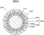
- FIG.4 is a cross sectional view showing an example of the structure of the insulated wire 2100 in another embodiment taken perpendicular to the longitudinal direction thereof.
- the cover layer 2120 arranged around the conductor 2110 has the laminated structure 2160 composed of the semiconducting layer 2130, a flame-retardant layer 2150 a arranged around the semiconducting layer 2130, the high-electrical insulating layer 2140 arranged around the flame-retardant layer 2150 a (arranged around the semiconducting layer 2130 via the flame-retardant layer 2150 a), and a flame-retardant layer 2150 b arranged around the high-electrical insulating layer 2140.
- the combined flame-retardant layer 2150 is composed of the flame-retardant layer 2150 a and the flame-retardant layer 2150 b.
- the flame-retardant layer 2150 has the flame-retardant layer 2150 a arranged on the inner side (on the conductor 2110 side) of the high-electrical insulating layer 2140, in addition to the flame-retardant layer 2150 b arranged on the outer side (on the opposite side to the conductor 2110 ) of the high-electrical insulating layer 2140.
- the flame-retardant layer 2150a is formed of a polymer composition containing a flame retardant in the same manner as the flame-retardant layer 2150 b and is formed by, e.g., extruding the polymer composition on the outer surface of the semiconducting layer 2130.
- the flame-retardant layer 2150 may have such a configuration, if required, to further increase, e.g., flame retardancy.
- the flame-retardant layer 2150 can be arranged only on the outer side of the high-electrical insulating layer 2140 or can be arranged on both the outer and inner sides of the high-electrical insulating layer 2140.
- the flame-retardant layer 2150 is preferably arranged at least on the outer side (on the outer surface) of the high-electrical insulating layer 2140.
- Insulated wires having the laminated structure shown in FIG.3 were made as Examples 3 to 5 and Comparative Examples 5 to 7 by the following procedure.
- the polymer composition (A) for forming a semiconducting layer, the polymer composition (B) for forming a high-electrical insulating layer and the polymer composition (C) for forming a flame-retardant layer were prepared.
- the mixing proportions for the polymer compositions (A) to (C) are shown in Tables 4 to 7.
- Conductors having an outer diameter of 1.23 mm were prepared.
- the polymer compositions (A), (B) and (C) were simultaneously extruded on each of the conductors and were cross-linked by electron beam irradiation to form the semiconducting layer, the high-electrical insulating layer and the flame-retardant layer, thereby obtaining each insulated wire.
- the semiconducting layer, the high-electrical insulating layer and the flame-retardant layer were formed in various thicknesses.
- the semiconducting layer was not formed. Table 7 shows the thickness of each layer and the total thickness of the cover layer.
- Insulating properties (electrical characteristics) and flame retardancy of the insulated wires in Examples 3 to 5 and Comparative Examples 5 to 7 were evaluated as follows. Table 7 shows the evaluation results.
- VFT vertical flame test
- VTFT vertical tray flame test
- VFT was conducted in accordance with the Test for vertical flame propagation for a single insulated wire or cable specified by EN 60332-1-2.
- 600 mm-long insulated wires were held vertical and a flame was applied thereto for 60 seconds.
- the wires passed the test ( ⁇ ) when the fire was extinguished within 60 seconds after removing the flame, and the wires failed the test ( ⁇ ) when the fire was not extinguished within 60 seconds.
- VTFT was conducted in accordance with the Test for vertical flame spread of vertically mounted bunched wires (Flame propagation in bunched cables) specified by EN 50266-2-4.
- seven 3.5 -meter insulated wires were twisted into one bundle, and eleven bundles were vertically arranged at equal intervals and were burnt for 20 minutes. Then, a char length from the lower end after self-extinction was measured.
- the wires with a char length of not more than 2.5 m were regarded as "Pass ( ⁇ ), and those with a char length of more than 2.5 m were regarded as "Fail ( ⁇ )".
- Example 3 the thickness of the semiconducting layer was 0.10 mm, the thickness of the high-electrical insulating layer was 0.11 mm, and the thickness of the flame-retardant layer was 0.29 mm.
- Example 4 the thickness of the semiconducting layer was 0.05 mm, the thickness of the high-electrical insulating layer was 0.15 mm, and the thickness of the flame-retardant layer was 0.30 mm.
- Example 5 the thickness of the semiconducting layer was 0.10 mm, the thickness of the high-electrical insulating layer was 0.08 mm, and the thickness of the flame-retardant layer was 0.29 mm.
- the thickness of the high-electrical insulating layer was not more than half the thickness of the flame-retardant layer in Examples 3 to 5, and specifically not more than one-third of the thickness of the flame-retardant layer in Example 5.
- the thickness of the semiconducting layer was not more than half the thickness of the flame-retardant layer in Examples 3 to 5, and specifically not more than one-third of the thickness of the flame-retardant layer in Example 4.
- the sum of the thickness of the semiconducting layer and the thickness of the high-electrical insulating layer was smaller than the thickness of the flame-retardant layer in Examples 3 to 5, and specifically not more than two-third of the thickness of the flame-retardant layer in Examples 4 and 5.
- the high-electrical insulating layer was thinner than the semiconducting layer.
- Comparative Example 5 the semiconducting layer was not formed, the thickness of the high-electrical insulating layer was 0.11 mm, and the thickness of the flame-retardant layer was 0.4 mm.
- Comparative Example 6 the thickness of the semiconducting layer was 0.10 mm, the thickness of the high-electrical insulating layer was 0.20 mm, and the thickness of the flame-retardant layer was 0.20 mm.
- Comparative Example 7 the thickness of the semiconducting layer was 0.20 mm, the thickness of the high-electrical insulating layer was 0.10 mm, and the thickness of the flame-retardant layer was 0.20 mm.
- the insulated wire in Comparative Example 5 had good flame retardancy due to having a thin high-electrical insulating layer, but failed the insulating property test since the semiconducting layer was not formed.
- the insulated wires in Comparative Examples 6 and 7 passed the insulating property test due to having the semiconducting layer, but failed the flam retardant test since the thickness of the high-electrical insulating layer was the same as the thickness of the flame-retardant layer in Comparative Example 6 and the thickness of the semiconducting layer was the same as the thickness of the flame-retardant layer in Comparative Example 7.
- insulated wires were made so that the respective layers had the same thicknesses as those in Example 5, but the polymer composition (A) to form the semiconducting layer, the polymer composition (B) to form the high-electrical insulating layer and the polymer composition (C) to form the flame-retardant layer were prepared with various mixing proportions.
- the similar characteristics as those described in Examples 3 to 5 were obtained.
- one of the insulated wires had a high-electrical insulating layer formed of the polymer composition (B) having a volume resistivity of the order of 10 16 ⁇ cm, and this shows that the polymer composition (B) having a volume resistivity of not less than 1x10 16 ⁇ cm can be used.
- one of the insulated wires had a semiconducting layer formed of the polymer composition (A) having a volume resistivity of the order of 10 8 ⁇ cm, and this shows that the polymer composition (A) having a volume resistivity of not more than 1x10 9 ⁇ cm can be used.
- An insulated wire comprising:
- the insulated wire defined by [18] or [19], wherein the thickness of the semiconducting layer is more preferably not more than half the thickness of the flame-retardant layer, further preferably not more than one-third of the thickness of the flame-retardant layer.
- the insulated wire defined by any one of [18] to [20], wherein the sum of the thickness of the semiconducting layer and the thickness of the high-electrical insulating layer is preferably smaller than the thickness of the flame-retardant layer, more preferably not more than two-third of the thickness of the flame-retardant layer.
- the insulated wire defined by any one of [18] to [21], wherein the high-electrical insulating layer receives preferably not less than 80 %, more preferably not less than 90 %, further preferably not less than 95 % of voltage applied in a thickness direction of a laminated portion of the high-electrical insulating layer and the flame-retardant layer.
- the insulated wire defined by any one of [18] to [22], wherein the polymer composition (B) has a volume resistivity of not less than 1x10 17 ⁇ cm.
- the insulated wire defined by any one of [18] to [23], wherein the volume resistivity of the polymer composition (B) constituting the high-electrical insulating layer is preferably not less than 10 times, more preferably not less than 50 times, further preferably not less than 100 times the volume resistivity of the polymer composition (C) constituting the flame-retardant layer.
- the insulated wire defined by any one of [18] to [24], wherein the outer diameter of the insulated wire is not more than 7 mm.
- the insulated wire defined by any one of [18] to [25], wherein the thickness of the semiconducting layer is not more than 0.10 mm.
- the insulated wire defined by any one of [18] to [26], wherein the thickness of the high-electrical insulating layer is preferably not more than 0.15 mm, more preferably not more than 0.10 mm.
- the insulated wire defined by any one of [18] to [27], wherein the thickness of the flame-retardant layer is not more than 0.30 mm.
- the insulated wire defined by any one of [18] to [28], wherein the semiconducting layer is arranged directly on the conductor (in contact with the conductor).
- the insulated wire defined by any one of [18] to [29], wherein the high-electrical insulating layer is arranged directly on the semiconducting layer (in contact with the semiconducting layer).
- the insulated wire defined by any one of [18] to [30], wherein the flame-retardant layer is also arranged between the semiconducting layer and the high-electrical insulating layer.
- the insulated wire defined by any one of [18] to [31], wherein the flame-retardant layer is arranged directly on the high-electrical insulating layer (in contact with the high-electrical insulating layer).
- the insulated wire defined by any one of [18] to [32], wherein the flame-retardant layer is the outermost layer of the insulated wire.
- the insulated wire defined by any one of [18] to [33], wherein the conductor is a twisted wire formed by twisting plural strands.
- the insulated wire defined by any one of [18] to [34], wherein the flame-retardant layer is an electrical insulating layer formed of the polymer composition (C) having a volume resistivity of not less than 1x10 13 ⁇ cm or not less than 1x10 14 ⁇ cm.
Landscapes
- Insulated Conductors (AREA)
Abstract
Description
- The invention relates to an insulated wire.
- Insulated wires used for wiring in rolling stocks or vehicles, etc., are required to have not only insulating properties but also flame retardancy so as not to be burnt easily in the event of fire. Thus, a flame retardant is mixed to cover layers of the insulated wires. For example,
JP-A-2010-97881 - In recent years, insulated wires are required to have a smaller diameter in view of, e.g., weight reduction. However, it is not easy to reduce a diameter while achieving high insulating properties and high flame retardancy.
- It is an object of the invention to provide an insulated wire that has a reduced diameter while satisfying high insulating properties and high flame retardancy.
- [1] According to an embodiment of the invention, an insulated wire comprises:
- a conductor; and
- a cover layer arranged around the conductor,
- wherein the cover layer comprises a laminated structure formed by laminating an inner flame-retardant layer, a high-electrical insulating layer and an outer flame-retardant layer,
- wherein the inner flame-retardant layer is arranged around the conductor and comprises a polymer composition (A) comprising a flame retardant,
- wherein the high-electrical insulating layer is arranged around the inner flame-retardant layer and comprises a polymer composition (B) having a volume resistivity of not less than 1x10¹⁶ Ωcm,
- wherein the outer flame-retardant layer is arranged around the high-electrical insulating layer and comprises a polymer composition (C) comprising a flame retardant,
- wherein the high-electrical insulating layer receives not less than 80% of voltage applied in a thickness direction of the laminated structure, and
- wherein the thickness of the high-electrical insulating layer is smaller than at least one of the thickness of the inner flame-retardant layer and the thickness of the outer flame-retardant layer.
- [2] According to another embodiment of the invention, an insulated wire comprises:
- a conductor; and
- a cover layer arranged around the conductor,
- wherein the cover layer comprises a semiconducting layer, a high-electrical insulating layer and a flame-retardant layer,
- wherein the semiconducting layer is arranged around the conductor and comprises a polymer composition (A) comprising a conductive agent and having a volume resistivity of not more than 1x10⁹ Ωcm,
- wherein the high-electrical insulating layer is arranged around the semiconducting layer and comprises a polymer composition (B) having a volume resistivity of not less than 1X10¹⁶ Ωcm,
- wherein the flame-retardant layer is arranged at least around the high-electrical insulating layer and comprises a polymer composition (C) comprising a flame retardant, and
- wherein the thickness of the high-electrical insulating layer and the thickness of the semiconducting layer are each smaller than the thickness of the flame-retardant layer.
- According to an embodiment of the invention, an insulated wire can be provided that has a reduced diameter while satisfying high insulating properties and high flame retardancy.
- Next, the present invention will be explained in more detail in conjunction with appended drawings, wherein:
-
FIG.1 is a cross sectional view showing an insulated wire in the first embodiment of the present invention taken perpendicular to the longitudinal direction thereof; -
FIG.2 is a cross sectional view showing a conventional insulated wire taken perpendicular to the longitudinal direction thereof; -
FIG.3 is a cross sectional view showing an insulated wire in the second embodiment of the invention taken perpendicular to the longitudinal direction thereof; -
FIG.4 is a cross sectional view showing an insulated wire in another embodiment taken perpendicular to the longitudinal direction thereof; and -
FIG.5 is a cross sectional view showing a conventional insulated wire taken perpendicular to the longitudinal direction thereof. - The inventors studied the insulated wire structure which allows a diameter to be reduced while achieving high insulating properties and high flame retardancy.
- A conventional wire structure will be firstly described, and the concept of the wire structure in the first embodiment of the present invention will be then described.
FIG.2 is a cross sectional view showing a conventional insulated wire taken perpendicular to the longitudinal direction thereof. - An insulated
wire 200 having a conventional structure has aconductor 210, aninsulation layer 220 arranged around theconductor 210, and a flame-retardant layer 230 arranged around theinsulation layer 220 and containing a flame retardant. - In case of the insulated
wire 200 which has a conventional structure, an additive having (some) flame retardancy (e.g., an inorganic filler such as calcium carbonate or clay) is mixed in a polymer composition constituting theinsulation layer 220 so that theinsulation layer 220 per se can have some flame retardancy. - Since a flame-retardant additive, etc. is mixed, the insulating properties of the polymer composition constituting the
insulation layer 220 is lower than the insulating properties of a base polymer used to form the polymer composition. When the base polymer of the polymer composition constituting theinsulation layer 220 is, e.g., polyethylene, a volume resistivity of the base polymer is, e.g., of the order of about 1x10¹⁶ Ωcm. A flame-retardant additive, etc., is then mixed to the polymer composition, and this reduces a volume resistivity of the polymer composition constituting theinsulation layer 220 down to the order of about 1x10 14 Ωcm. - The inventors examined if the thinner flame-
retardant layer 230 can be provided to reduce a diameter of the insulatedwire 200. However, only by reducing the thickness of the flame-retardant layer 230 (without changing the thickness of the insulation layer 220), the insulatedwire 200 cannot have high flame retardancy. - Then, it was examined if the
thinner insulation layer 220 can be provided. However, when simply reducing the thickness of theinsulation layer 220, the insulatedwire 200 cannot have high insulating properties. Therefore, it was examined if the amount of a flame-retardant additive, etc., mixed to theinsulation layer 220 can be reduced so that the insulating properties of the polymer composition constituting theinsulation layer 220 are increased closer to high insulating properties of the base polymer. However, when simply reducing the amount of the flame-retardant additive, etc., mixed to theinsulation layer 220, theinsulation layer 220 cannot have sufficient flame retardancy. - Based on the above, the inventors conceived a new structure in which the
insulation layer 220 is divided into a flame-retardant layer containing a flame-retardant additive and arranged on the inner side (on the conductor side) and an insulation layer containing a reduced amount of flame-retardant additive, etc., and arranged on the outer side (on the opposite side to the conductor). Hereinafter, the insulation layer containing a reduced amount of flame-retardant additive, etc., is referred to as "high-electrical insulating layer". Then, the flame-retardant layer arranged on the inner side of the high-electrical insulating layer is referred to as "inner flame-retardant layer" and a flame-retardant layer arranged on the outer side of high-electrical insulating layer is referred to as "outer flame-retardant layer". - In such a structure, when the high-electrical insulating layer is formed of a polymer composition of which insulating properties is enhanced (a decrease in insulating properties is suppressed) by reducing the mixed amount of flame-retardant additive, etc., the thickness of the high-electrical insulating layer required to obtain desired insulating properties can be reduced. In addition, it is also possible to obtain desired flame retardancy by the inner flame-retardant layer and the outer flame-retardant layer. Furthermore, since the thickness of the easily combustible high-electrical insulating layer can be reduced, it is possible to reduce the thicknesses of the inner flame-retardant layer and the outer flame-retardant layer, i.e., to reduce the thickness of the combined flame-retardant layer.
- By reducing the mixed amount of flame-retardant additive, etc., the volume resistivity of the polymer composition constituting the high-electrical insulating layer can be significantly increased to, e.g., about 100 times higher than the volume resistivity of the polymer composition originally used to form the
insulation layer 220. Thus, reducing the thickness of the insulation layer by increasing the volume resistivity while achieving desired insulating properties is easier way than reducing the thickness of the flame-retardant layer. - In general, conductors have a twisted wire structure formed by twisting strands and thus have bumps and recesses on a surface thereof. If the high-electrical insulating layer is arranged directly on the conductor, the high-electrical insulating layer is likely to be broken due to electric field concentration caused by the bumps and recesses on the surface of the conductor and the thickness of the high-electrical insulating layer thus should not be reduced. Since the inner flame-retardant layer, which is arranged directly on the conductor and covers the bumps and recesses, serves as a bump-and-recess smoothing layer, the high-electrical insulating layer which is arranged on the inner flame-retardant layer can have a reduced thickness.
- The wire structure, which allows for diameter reduction while achieving high insulating properties and high flame retardancy, is thus obtained.
- Such wire structure is preferably applied to, e.g., a thin insulated wire which has an outer diameter (a cross-sectional diameter) of not more than 3 mm. The insulating properties of insulated wire are evaluated by, e.g., a DC stability test which is described later. Flame retardancy of insulated wire is evaluated by, e.g., VFT or VTFT which are also described later. The intended use of the insulated wire is not specifically limited and is, e.g., for rolling stocks, vehicles or medical application.
- Next, an
insulated wire 100 in the first embodiment of the invention will be described in reference toFIG.1. FIG.1 is a cross sectional view showing an example of the structure of theinsulated wire 100 taken perpendicular to the longitudinal direction thereof. - The
insulated wire 100 has aconductor 110 and acover layer 120 arranged around theconductor 110. - The
conductor 110 used here can be, e.g., a twisted wire formed by twisting plural strands (metal wires). The strand can be, e.g., a copper wire, a copper alloy wire, an aluminum wire, a gold wire or a silver wire, etc., or may be a wire of which outer surface is plated with a metal such as tin or nickel. The outer diameter (the cross-sectional diameter) of theconductor 110 is, e.g., not less than 0.70 mm and not more than 1.70 mm. The outer diameter (the cross-sectional diameter) of the strand is, e.g., not less than 0.10 mm and not more than 0.30 mm. The material, structure and size, etc., of theconductor 110 can be appropriately selected according to the characteristics required for theconductor 110 of theinsulated wire 100. - The
cover layer 120 has alaminated structure 150 composed of an inner flame-retardant layer 131 arranged around theconductor 110, a high-electricalinsulating layer 140 arranged around the inner flame-retardant layer 131, and an outer flame-retardant layer 132 arranged around the high-electricalinsulating layer 140. The combined flame-retardant layer 130 is composed of the inner flame-retardant layer 131 and the outer flame-retardant layer 132. - The inner flame-
retardant layer 131, i.e., a flame-retardant layer 131 arranged on the inner side (on theconductor 110 side) of the high-electricalinsulating layer 140, is formed of a polymer composition (A) containing a flame retardant. The inner flame-retardant layer 131 is formed by, e.g., extruding the polymer composition (A) on the outer surface of theconductor 110. - A base polymer of the polymer composition (A) is e.g. a polyolefin resin. The polyolefin resin used here can be, e.g., a polyethylene-based resin, etc. Examples of the polyethylene-based resin used here include polyethylene such as low-density polyethylene (LDPE), linear low-density polyethylene (LLDPE) and high-density polyethylene (HDPE), ethylene-vinyl acetate copolymer (EVA), ethylene-ethyl acrylate copolymer, ethylene-methyl acrylate copolymer and ethylene-glycidyl methacrylate copolymer, etc. These polyolefin resins may be used alone or in combination of two or more.
- The base polymer of the polymer composition (A) preferably contains, e.g., EVA. EVA is preferable since its relatively high filler acceptability allows a flame retardant to be added easily and the resin per se has some flame retardancy.
- The flame retardant added to the polymer composition (A) is preferably a halogen-free flame retardant since it does not produce toxic gas, and for example, a metal hydroxide can be preferably used. As the metal hydroxide, it is possible to use, e.g., magnesium hydroxide, aluminum hydroxide, calcium hydroxide and these metal hydroxides with dissolved nickel. These flame retardants may be used alone or in a combination of two or more.
- The flame retardant is preferably surface-treated with, e.g., a silane coupling agent, a titanate-based coupling agent, fatty acid such as stearic acid, fatty acid salt such as stearate, or fatty acid metal such as calcium stearate to control mechanical characteristics (a balance between tensile strength and elongation) of the inner flame-
retardant layer 131. The amount of the flame retardant to be mixed is preferably, e.g., not less than 100 parts by mass and not more than 250 parts by mass with respect to 100 parts by mass of the base polymer. When the mixed amount is less than 100 parts by mass, desired high flame retardancy may not be obtained. When the mixed amount is more than 250 parts by mass, mechanical characteristics of the inner flame-retardant layer 131 may decrease, resulting in a decrease in elongation percentage. - The inner flame-
retardant layer 131 is preferably formed of the cross-linked polymer composition (A) to improve flame retardancy and heat resistance. The crosslinking method can be, e.g., radiation crosslinking, chemical crosslinking or silane crosslinking, etc. The polymer composition (A) may contain a crosslinking aid or a cross-linking agent so as to be well cross-linked. Since radiation crosslinking is preferable to cross-link the high-electricalinsulating layer 140 as described later, it is efficient to cross-link the inner flame-retardant layer 131 by radiation crosslinking at the same time as radiation crosslinking of the high-electricalinsulating layer 140, i.e., in the same process as radiation crosslinking of the high-electricalinsulating layer 140. - The inner flame-
retardant layer 131 is, e.g., an electrical insulating layer formed of the polymer composition (A) with a volume resistivity of about 1x10¹⁴ Ωcm (or more). In this regard, where the inner flame-retardant layer 131 is formed of the cross-linked polymer composition (A), the volume resistivity of the polymer composition (A) is defined as the volume resistivity of the cross-linked polymer composition (A). - The polymer composition (A) may contain, if required, other additives, e.g., carbon fiber, talc and clay, etc., as long as the characteristics of the inner flame-
retardant layer 131 are not impaired. - The high-electrical
insulating layer 140 is formed of a polymer composition (B) having a volume resistivity of not less than 1x10¹⁶ Ωcm. The high-electricalinsulating layer 140 is formed by, e.g., extruding the polymer composition (B) on the outer surface of the inner flame-retardant layer 131. - A base polymer of the polymer composition (B) is a polymer having a volume resistivity of not less than 1x10¹⁶ Ωcm, e.g., polyolefin resin, etc. The polyolefin resin used here can be, e.g., polyethylene such as LDPE, LLDPE or HDPE. These polyolefin resins may be used alone or in combination of two or more.
- The base polymer of the polymer composition (B) preferably contains, e.g., polyethylene. Polyethylene is preferable since its volume resistivity can be improved by cross-linking. The polyethylene used here may be any of LDPE, LLDPE and HDPE. LDPE may be used since it is easily cross-linked.
- The high-electrical
insulating layer 140 is preferably formed of the cross-linked polymer composition (B) to improve the volume resistivity The crosslinking method can be, e.g., radiation crosslinking, chemical crosslinking or silane crosslinking, etc. The polymer composition (B) may contain a crosslinking aid or a cross-linking agent so as to be well cross-linked. Particularly, radiation crosslinking not requiring addition of additives is preferable to prevent a decrease in electrical insulating properties. - When the high-electrical
insulating layer 140 is formed of the cross-linked polymer composition (B), the volume resistivity of the polymer composition (B) means the volume resistivity of the cross-linked polymer composition (B). - It is preferable that the polymer composition (B) contain as little additives as possible to suppress as decrease in the volume resistivity, but if required, various additives may be contained a long as the volume resistivity of not less than 1x10¹⁶ Ωcm can be maintained. Examples of the additives include antioxidant and copper inhibitor, etc.
- It is preferable that the polymer composition (B) do not contain, e.g., inorganic filler such as calcium carbonate, clay, talc, silica, wollastonite, zeolite, diatomaceous earth, silica sand, pumice powder, slate powder, alumina, aluminum sulfate, barium sulfate, lithopone, calcium sulfate and molybdenum disulfide, or flame retardant such as metal hydroxide to prevent a decrease in volume resistivity of the polymer composition (B).
- The outer flame-
retardant layer 132, i.e., a flame-retardant layer 132 arranged on the outer side (on the opposite side to the conductor 110) of the high-electricalinsulating layer 140, is formed of a polymer composition (C) containing a flame retardant. The outer flame-retardant layer 132 is formed by, e.g., extruding the polymer composition (C) on the outer surface of the high-electricalinsulating layer 140. - A base polymer of the polymer composition (C) is, e.g., the same as the base polymer of the polymer composition (A) constituting the inner flame-
retardant layer 131, and is preferably, e.g., a polymer containing EVA. The base polymer of the polymer composition (C) constituting the outer flame-retardant layer 132 may be the same as or different from the base polymer of the polymer composition (A) constituting the inner flame-retardant layer 131. - The flame retardant added to the polymer composition (C) is, e.g., the same as that added to the polymer composition (A) constituting the inner flame-
retardant layer 131, and is preferably, e.g., a metal hydroxide. The amount of the flame retardant to be mixed can be, e.g., the same as the amount of the flame retardant to be mixed to the polymer composition (A) constituting the inner flame-retardant layer 131. The flame retardant added to the polymer composition (C) constituting the outer flame-retardant layer 132 may be the same as or different from the flame retardant added to the polymer composition (A) constituting the inner flame-retardant layer 131. Likewise, the amount of the flame retardant mixed in the polymer composition (C) may be the same as or different from that in the polymer composition (A). - The outer flame-
retardant layer 132 is preferably formed of the cross-linked polymer composition (C) to improve flame retardancy and heat resistance. The crosslinking method can be, e.g., radiation crosslinking, chemical crosslinking or silane crosslinking, etc. The polymer composition (C) may contain a crosslinking aid or a cross-linking agent so as to be well cross-linked. Since radiation crosslinking is preferable to cross-link the high-electricalinsulating layer 140, it is efficient to cross-link the outer flame-retardant layer 132 by radiation crosslinking at the same time as radiation crosslinking of the high-electricalinsulating layer 140, i.e., in the same process as radiation crosslinking of the high-electricalinsulating layer 140. - The outer flame-
retardant layer 132 is, e.g., an electrical insulating layer formed of the polymer composition (C) with a volume resistivity of about 1x10¹⁴ Ωcm (or more). In this regard, when the outer flame-retardant layer 132 is formed of the cross-linked polymer composition (C), the volume resistivity of the polymer composition (C) means the volume resistivity of the cross-linked polymer composition (C). - The polymer composition (C) may contain, if required, other additives, e.g., carbon fiber, talc and clay, etc., as long as the characteristics of the outer flame-
retardant layer 132 are not impaired. - Next, the
laminated structure 150 of thecover layer 120 composed of the inner flame-retardant layer 131, the high-electricalinsulating layer 140 and the outer flame-retardant layer 132 will be further described. - The high-electrical
insulating layer 140 is configured to receive preferably not less than 80%, more preferably not less than 90%, further preferably not less than 95%, of voltage applied in the thickness direction of thelaminated structure 150. - Thus, voltage applied to each of the inner flame-
retardant layer 131 and the outer flame-retardant layer 132 can be reduced accordingly. In the inner flame-retardant layer 131 and the outer flame-retardant layer 132 which contain many additives such as flame retardant, insulation breakdown is more likely to occur than in the high-electricalinsulating layer 140. High insulating properties of theinsulated wire 100 can be achieved by reducing voltage applied to the inner flame-retardant layer 131 and the outer flame-retardant layer 132. - Meanwhile, the high-electrical
insulating layer 140 is formed thinner than at least one of the inner flame-retardant layer 131 and the outer flame-retardant layer 132. - This reduces the thickness of the
laminated structure 150 and thus reduces the diameter of theinsulated wire 100, and at the same time, high flame retardancy is achieved since flammability of thelaminated structure 150 due to having the high-electricalinsulating layer 140 is reduced by the inner flame-retardant layer 131 and the outer flame-retardant layer 132. Along with the thickness reduction of the easily combustible high-electricalinsulating layer 140, the thickness of the combined flame-retardant layer 130 (the inner flame-retardant layer 131 and the outer flame-retardant layer 132) can be also reduced. - In order to form the high-electrical
insulating layer 140 so as to receive not less than 80% of voltage applied to thelaminated structure 150 and also to be thinner than at least one of the inner flame-retardant layer 131 and the outer flame-retardant layer 132, the volume resistivity of the polymer composition (B) constituting the high-electricalinsulating layer 140 is preferably at least not less than 1x10¹⁶ Ωcm, more preferably not less than 1x10¹⁷ Ωcm. The upper limit of the volume resistivity of the polymer composition (B) is not specifically limited. - In order to form the high-electrical
insulating layer 140 so as to receive not less than 80% of voltage applied to thelaminated structure 150 and also to be thinner than at least one of the inner flame-retardant layer 131 and the outer flame-retardant layer 132. the volume resistivity of the polymer composition (B) constituting the high-electricalinsulating layer 140 is preferably not less than 10 times, more preferably not less than 50 times, further preferably not less than 100 times the volume resistivity of the polymer composition (A) constituting the inner flame-retardant layer 131 and that of the polymer composition (C) constituting the outer flame-retardant layer 132. - To reduce the diameter while achieving high flame retardancy, the thickness of the high-electrical
insulating layer 140 is more preferably not more than half the thickness of the combined flame-retardant layer 130 (the sum of the thickness of the inner flame-retardant layer 131 and the thickness of the outer flame-retardant layer 132), further preferably not more than half of at least one of the thickness of the inner flame-retardant layer 131 and the thickness of the outer flame-retardant layer 132. - To be a thin insulated wire, the outer diameter (the cross-sectional diameter) of the
insulated wire 100 is preferably not more than 3 mm, more preferably not more than 2.5 mm. The rated (AC) voltage of theinsulated wire 100 is, e.g., not more than 660V (600V, as an example). Having a small diameter is also advantageous in that it is easy to simultaneously cross-link the inner flame-retardant layer 131, the high-electricalinsulating layer 140 and the outer flame-retardant layer 132 by radiation crosslinking. - In view of diameter reduction, the upper limit of the thickness of the high-electrical
insulating layer 140 is, e.g., preferably not more than 0.2 mm, more preferably not more than 0.15 mm. Meanwhile, the lower limit of the thickness of the high-electricalinsulating layer 140 is not specifically limited as long as desired insulating properties are obtained, but not less than 0.05 mm is preferable so that, for example, the high-electricalinsulating layer 140 can have a highly uniform thickness and resulting stable insulating properties can be obtained. - To obtain flame retardancy of the
insulated wire 100, the combined flame-retardant layer 130 is formed to have a well-balanced, sufficiently large thickness which can prevent the high-electricalinsulating layer 140 from burning. To obtain such thickness, the respective thicknesses of the inner flame-retardant layer 131 and the outer flame-retardant layer 132 can be appropriately changed, if required, in a well-balanced manner so that the combined flame-retardant layer 130 can have a sufficient thickness. For example, the outer flame-retardant layer 132 can be thicker than the inner flame-retardant layer 131, the inner flame-retardant layer 131 can be thicker than the outer flame-retardant layer 132, or, the inner flame-retardant layer 131 and the outer flame-retardant layer 132 can have the same thickness. However, to increase flame retardancy, the outer flame-retardant layer 132 is preferably thicker than the inner flame-retardant layer 131. The thickness of the combined flame-retardant layer 130 is preferably, e.g., not less than double the high-electricalinsulating layer 140. - In view of diameter reduction, the upper limit of the thickness of the combined flame-
retardant layer 130 is, e.g., preferably not more than 0.4 mm. Meanwhile, the lower limit of the thickness of the combined flame-retardant layer 130 is not specifically limited as long as it is determined according to the thickness of the high-electricalinsulating layer 140 and the flame retardancy can be obtained, but not less than 0.2 mm is preferable to obtain, e.g., stable flame retardancy. - The inner flame-
retardant layer 131 is arranged directly on the conductor 110 (in contact with the conductor 110) and covers the bumps and recesses on the surface of theconductor 110, thereby serving as a bump-and-recess smoothing layer to prevent electric field concentration. Thus, the high-electricalinsulating layer 140 which is arranged on the inner flame-retardant layer 131 can have a reduced thickness. The thickness of the inner flame-retardant layer 131 here is expressed as a thickness on the bumps of the twist on the surface of the conductor 110 (a thickness of the thinnest portion), i.e., a thickness from the outer diameter of theconductor 110. - The upper limit of the thickness of the inner flame-
retardant layer 131 can be appropriately selected within the thickness range of the combined flame-retardant layer 130, and is not specifically limited. Meanwhile, the lower limit of the thickness of the inner flame-retardant layer 131 is not specifically limited, but is preferably not less than 0.05 mm so that, for example, the bumps and recesses on the surface of theconductor 110 are sufficiently covered, and also, the inner flame-retardant layer 131 can have a highly uniform thickness and resulting stable flame retardancy can be obtained. - The upper limit of the thickness of the outer flame-
retardant layer 132 can be appropriately selected within the thickness range of the combined flame-retardant layer 130, and is not specifically limited. Meanwhile, the lower limit of the thickness of the outer flame-retardant layer 132 is not specifically limited, but is preferably not less than 0.05 mm so that, for example, the outer flame-retardant layer 132 can have a highly uniform thickness and resulting stable flame retardancy can be obtained. - In view of diameter reduction, preferably, another layer is not arranged between the inner flame-
retardant layer 131 and the high-electricalinsulating layer 140. In other words, the high-electricalinsulating layer 140 is preferably arranged directly on the inner flame-retardant layer 131 (in contact with the inner flame-retardant layer 131). Likewise, preferably, another layer is not arranged between the high-electricalinsulating layer 140 and the outer flame-retardant layer 132. In other words, the outer flame-retardant layer 132 is preferably arranged directly on the high-electrical insulating layer 140 (in contact with the high-electrical insulating layer 140). Furthermore, preferably, another layer is not arranged around the outer flame-retardant layer 132. In other words, it is preferable that the outer flame-retardant layer 132 be the outermost layer of thecover layer 120, i.e., the outermost layer of theinsulated wire 100. - The inner flame-
retardant layer 131, the high-electricalinsulating layer 140 and the outer flame-retardant layer 132 are preferably simultaneously extruded on theconductor 110. In this case, air dust to be a cause of electric field concentration can be prevented from attaching to a boundary surface between the inner flame-retardant layer 131 and the high-electricalinsulating layer 140 and to a boundary surface between the high-electricalinsulating layer 140 and the outer flame-retardant layer 132. - Alternatively, the inner flame-
retardant layer 131 may have, if required, a laminated structure composed of plural flame-retardant layers (sub-flame-retardant layers). Likewise, the high-electricalinsulating layer 140 may have, if required, a laminated structure composed of plural insulating layers (sub-insulating layers). Also, the outer flame-retardant layer 132 may have, if required, a laminated structure composed of plural flame-retardant layers (sub-flame-retardant layers). - As described above, in the first embodiment, it is possible to reduce a diameter of the insulated wire while achieving high insulating properties and high flame retardancy.
- The insulated wire in the first embodiment can be used alone, and also can be used, if required, in combination with another member, e.g., used as a core of a cable.
- The invention will be described in more detail below in reference to Examples. However, the invention is not limited thereto.
- Insulated wires in Examples 1, 2 and Comparative Examples 1 to 4 were made as follows.
- The polymer composition (A) for forming an inner flame-retardant layer, the polymer composition (B) for forming a high-electrical insulating layer and the polymer composition (C) for forming an outer flame-retardant layer were prepared. The same polymer composition was prepared as the polymer composition (A) for forming an inner flame-retardant layer and the polymer composition (C) for forming an outer flame-retardant layer. As the polymer composition (B) for forming a high-electrical insulating layer, three types of polymer compositions (compositions 1 to 3) with various volume resistivities were prepared according to the different volume resistivities of the high-electrical insulating layers of the respective samples. The mixing proportions for the polymer compositions (A) and (C) are shown in Table 1, and the mixing proportions for the polymer compositions (B) are shown in Table 2.
Table 1 Polymer compositions (A) and (C) for forming Inner and Outer flame-retardant layers Base polymer EVA 85 Acid-modified polyolefin resin 15 Flame retardant Magnesium hydroxide 200 Colorant FT carbon 2 Lubricant Zinc stearate 1 Table 2 Polymer composition (B) for forming High-electrical insulating layer Composition 1 (Example 1) Composition 2 (Example 2) Composition 3 (Comparative Example 1 to 4) Base polymer High-density polyethylene 100 - - Linear low-density polyethylene - 100 100 Inorganic filler Clay - - 100 Volume resistivity (Ωcm) 1.34E+17 9.48E+16 1.60E+15 - Conductors having an outer diameter of 1.23 mm (each formed by twisting thirty-seven 0.18 mm-diameter tin-plated copper strands) were prepared. The polymer compositions (A), (B) and (C) were simultaneously extruded on each of the conductors and were cross-linked by electron beam irradiation, thereby forming the inner flame-retardant layer, the high-electrical insulating layer and the outer flame-retardant layer.
- The high-electrical insulating layers of the insulated wires in Examples 1, 2 and Comparative Examples 1 to 4 had different volume resistivities, i.e., were formed of the polymer compositions (B) with different mixing proportions. Also, the outer flame-retardant layer and the high-electrical insulating layer were formed in various thicknesses. The volume resistivity was the same between the inner flame-retardant layer and the outer flame-retardant layer, and was fixed for all of Examples 1, 2 and Comparative Examples 1 to 4. The thickness of the inner flame-retardant layer was also fixed.
- Table 3 shows the configuration of the insulated wires of Examples 1, 2 and Comparative Examples 1 to 4; volume resistivity of the polymer composition used to form the flame-retardant layer (volume resistivity of the flame-retardant layer), volume resistivity of the polymer composition used to form the high-electrical insulating layer (volume resistivity of the high-electrical insulating layer), thickness of the high-electrical insulating layer, thickness of the inner flame-retardant layer and thickness of the outer flame-retardant layer.
- Table 3 also shows a voltage sharing rate in the laminated structure composed of the inner flame-retardant layer, the high-electrical insulating layer and the outer flame-retardant layer, i.e., a ratio of resistance of the high-electrical insulating layer to the sum of resistance of the inner flame-retardant layer, resistance of the high-electrical insulating layer and resistance of the outer flame-retardant layer, in the thickness direction of the laminated structure.
Table 3 Example 1 Example 2 Comparative Example 1 Comparative Example 2 Comparative Example 3 Comparative Example 4 Volume resistivity of flame-retardant layer (Ωcm) 4.00E+14 4.00E+14 4.00E+14 4.00E+14 4.00E+14 4.00E+14 Volume resistivity of high-electrical insulating layer (Ωcm) 1.34E+17 9.48E+16 1.60E+15 1.60E+14 1.60E+14 1.60E+14 Thickness of high-electrical insulating layer (mm) 0.11 0.18 0.11 0.2 0.11 0.18 Thickness of inner flame-retardant layer (mm) 0.1 0.1 0.1 0.1 0.1 0.1 Thickness of outer flame-retardant layer (mm) 0.3 0.3 0.3 0.3 0.1 0.15 Voltage sharing rate (%) 98.9 99.1 52.4 66.7 68.8 74.2 DC stability test (hour) Not less than 240 Not less than 240 108 67 112 119 Flame retardancy VFT ⊚ ⊚ ⊚ ⊚ × × VTFT ⊚ ○ ⊚ ○ × × Overall evaluation ○ ○ × × × × - Insulating properties (electrical characteristics) and flame retardancy of the insulated wires in Examples 1, 2 and Comparative Examples 1 to 4 were evaluated as follows. Table 3 shows the evaluation results.
- To evaluate electrical characteristics, i.e., insulation reliability, of the insulated wires, a DC stability test was conducted by applying 300V DC voltage to the insulated wires in 3% NaCl solution at 85°C in accordance with EN 50305.6.7. The wires with no short-circuit for 10 days, i.e., time to short-circuit of not less than 240 hours, were regarded as "Pass", and those short-circuited within 10 days, i.e., time to short-circuit of less than 240 hours, were regarded as "Fail".
- Flame-retardancy of the insulated wires was evaluated by the following flame tests (vertical flame test: VFT and vertical tray flame test: VTFT).
- VFT was conducted in accordance with the Test for vertical flame propagation for a single insulated wire or cable specified by EN 60332-1-2. In detail, 600 mm-long insulated wires were held vertical and a flame was applied thereto for 60 seconds. The wires passed the test (⊚: excellent) when the fire was extinguished within 30 seconds after removing the flame, the wires passed the test (○: acceptable) when the fire was extinguished within 60 seconds, and the wires failed the test (×) when the fire was not extinguished within 60 seconds.
- VTFT was conducted in accordance with the Test for vertical flame spread of vertically mounted bunched wires (Flame propagation in bunched cables) specified by EN 50266-2-4. In detail, seven 3.5-meter insulated wires were twisted into one bundle, and eleven bundles were vertically arranged at equal intervals and were burnt for 20 minutes. Then, a char length from the lower end after self-extinction was measured. The wires with a char length of not more than 1.5 m were regarded as "Pass (⊚: excellent)", those with a char length of not more than 2.5 m were regarded as "Pass (○: acceptable)", and those with a char length of more than 2.5 m were regarded as "Fail (×)".
- The overall evaluation was rated as "Pass (○)" for the insulated wires which passed both the electrical characteristic and flame retardant tests, and the others were rated as "Fail (×)".
- The volume resistivity of the flame-retardant layer was 4x10¹⁴ Ωcm in both Examples 1 and 2, the volume resistivity of the high-electrical insulating layer was 1.34x10¹⁷ Ωcm in Example 1 and 9.48x10¹⁶ Ωcm in Example 2, and the voltage sharing rate of the high-electrical
insulating layer 140 was 98.9% in Example 1 and 99.1% in Example 2. The thickness of the inner flame-retardant layer was 0.1 mm in both Examples 1 and 2, and the thickness of the outer flame-retardant layer was 0.3 mm in both Examples 1 and 2. The thickness of the high-electrical insulating layer was 0.11 mm in Example 1 and 0.18 mm in Example 2. - The insulated wires in Examples 1 and 2 passed both the electrical characteristic and flame retardant tests since the volume resistivity of the high-electrical insulating layer was not less than 1x10¹⁶ Ωcm, the voltage sharing rate of the high-electrical insulating layer was not less than 80%, and furthermore, the high-electrical insulating layer was thinner than at least one of the inner flame-retardant layer and the outer flame-retardant layer. In both Examples 1 and 2, the voltage sharing rate of the high-electrical insulating layer not only just satisfied the condition of not less than 80%, but also achieved the conditions of not less than 90% and not less than 95%.
- The thickness of the combined flame-retardant layer (the inner flame-retardant layer and the outer flame-retardant layer) was 0.4 mm in both Examples 1 and 2, and the thickness of the high-electrical insulating layer was not more than half the thickness of the combined flame-retardant layer (specifically, not more than 0.2 mm) in both Examples 1 and 2. In Example 1, since the thickness of the high-electrical insulating layer was not more than half of at least one of the thickness of the inner flame-retardant layer and the thickness of the outer flame-retardant layer (more specifically, not more than 0.15 mm), higher flame retardancy and smaller diameter than Example 2 were obtained. In Example 1, since the volume resistivity of the high-electrical insulating layer was not less than 1x10¹⁷ Ωcm, it was possible to obtain the thinner high-electrical insulating layer than Example 2.
- Meanwhile, a ratio of the volume resistivity of the high-electrical insulating layer to the volume resistivity of the flame-retardant layer was 335 times in Example 1 and 237 times in Example 2, and the conditions of 10 times, not less than 50 times, and not less than 100 times were satisfied in both Examples 1 and 2.
- The volume resistivity of the flame-retardant layer was 4x10¹⁴ Ωcm in both Comparative Examples 1 and 2, the volume resistivity of the high-electrical insulating layer was 1.60x10¹⁵ Ωcm in both Comparative Examples 1 and 2. The voltage sharing rate of the high-electrical
insulating layer 140 was 52.4% in Comparative Example 1 and 66.7% in Comparative Example 2. The thickness of the inner flame-retardant layer was 0.1 mm in both Comparative Examples 1 and 2, and the thickness of the outer flame-retardant layer was 0.3 mm in both Comparative Examples 1 and 2. The thickness of the high-electrical insulating layer was 0.11 mm in Comparative Example 1 and 0.2 mm in Comparative Example 2. - The insulated wires in Comparative Examples 1 and 2 failed the electrical characteristic test since the volume resistivity of the high-electrical insulating layer was less than 1x10¹⁶ Ωcm and the voltage sharing rate of the high-electrical insulating layer was less than 80%. However, the samples passed the flame retardant test since the high-electrical insulating layer was thinner than at least one of the inner flame-retardant layer and the outer flame-retardant layer. Meanwhile, the ratio of the volume resistivity of the high-electrical insulating layer to the volume resistivity of the flame-retardant layer was 4 times in both Comparative Examples 1 and 2, which is less than 10 times.
- The volume resistivity of the flame-retardant layer was 4x10¹⁴ Ωcm in both Comparative Examples 3 and 4, the volume resistivity of the high-electrical insulating layer was 1.60x10¹⁵ Ωcm in both Comparative Examples 3 and 4. The voltage sharing rate of the high-electrical
insulating layer 140 was 68.8% in Comparative Example 3 and 74.2% in Comparative Example 4. The thickness of the inner flame-retardant layer was 0.1 mm in both Comparative Examples 3 and 4, and the thickness of the outer flame-retardant layer was 0.1 mm in Comparative Example 3 and 0.15 mm in Comparative Example 4. The thickness of the high-electrical insulating layer was 0.11 mm in Comparative Example 3 and 0.18 mm in Comparative Example 4. - The insulated wires in Comparative Examples 3 and 4 failed electrical characteristic test since the volume resistivity of the high-electrical insulating layer was less than 1x10¹⁶ Ωcm and the voltage sharing rate of the high-electrical insulating layer was less than 80%. Furthermore, the samples also failed the flame retardant test since the high-electrical insulating layer was thicker than both the inner flame-retardant layer and the outer flame-retardant layer. Meanwhile, the ratio of the volume resistivity of the high-electrical insulating layer to the volume resistivity of the flame-retardant layer was 4 times in both Comparative Examples 3 and 4, which is less than 10 times.
- Although the invention has been described in reference to the first embodiment, the invention is not limited thereto. It will be obvious for those skilled in the art that various changes, modifications and combinations, etc., can be implemented.
- Preferred embodiments of the invention will be described below.
- [1] An insulated wire, comprising:
- a conductor; and
- a cover layer arranged around the conductor,
- wherein the cover layer comprises a laminated structure formed by laminating an inner flame-retardant layer, a high-electrical insulating layer and an outer flame-retardant layer, the inner flame-retardant layer being arranged around the conductor and comprising a polymer composition (A) containing a flame retardant, the high-electrical insulating layer being arranged around the inner flame-retardant layer and comprising a polymer composition (B) having a volume resistivity of not less than 1x10¹⁶ Ωcm, and the outer flame-retardant layer being arranged around the high-electrical insulating layer and comprising a polymer composition (C) containing a flame retardant, the high-electrical insulating layer receives not less than 80% of voltage applied in a thickness direction of the laminated structure, and the thickness of the high-electrical insulating layer is smaller than at least one of the thickness of the inner flame-retardant layer and the thickness of the outer flame-retardant layer.
- [2] The insulated wire defined by [1], wherein the high-electrical insulating layer receives more preferably not less than 90%, further preferably not less than 95% of the voltage applied in the thickness direction of the laminated structure.
- [3] The insulated wire defined by [1] or [2], wherein the polymer composition (B) has a volume resistivity of not less than 1x10¹⁷ Ωcm.
- [4] The insulated wire defined by any one of [1] to [3], wherein the volume resistivity of the polymer composition (B) constituting the high-electrical insulating layer is preferably not less than 10 times, more preferably not less than 50 times, further preferably not less than 100 times the volume resistivity of the polymer composition (A) constituting the inner flame-retardant layer.
- [5] The insulated wire defined by any one of [1] to [4], wherein the volume resistivity of the polymer composition (B) constituting the high-electrical insulating layer is preferably not less than 10 times, more preferably not less than 50 times, further preferably not less than 100 times the volume resistivity of the polymer composition (C) constituting the outer flame-retardant layer.
- [6] The insulated wire defined by any one of [1] to [5], wherein the thickness of the high-electrical insulating layer is not more than half the sum of the thickness of the inner flame-retardant layer and the thickness of the outer flame-retardant layer.
- [7] The insulated wire defined by any one of [1] to [6], wherein the thickness of the high-electrical insulating layer is not more than half of at least one of the thickness of the inner flame-retardant layer and the thickness of the outer flame-retardant layer.
- [8] The insulated wire defined by any one of [1] to [7], wherein the outer diameter of the insulated wire is preferably not more than 3 mm, more preferably not more than 2.5 mm.
- [9] The insulated wire defined by any one of [1] to [8], wherein the thickness of the high-electrical insulating layer is preferably not more than 0.2 mm, more preferably not more than 0.15 mm.
- [10] The insulated wire defined by any one of [1] to [9], wherein the sum of the thickness of the inner flame-retardant layer and the thickness of the outer flame-retardant layer is not more than 0.4 mm.
- [11] The insulated wire defined by any one of [1] to [10], wherein the inner flame-retardant layer is arranged directly on the conductor (in contact with the conductor).
- [12] The insulated wire defined by any one of [1] to [11], wherein the high-electrical insulating layer is arranged directly on the inner flame-retardant layer (in contact with the inner flame-retardant layer).
- [13] The insulated wire defined by any one of [1] to [12], wherein the outer flame-retardant layer is arranged directly on the high-electrical insulating layer (in contact with the high-electrical insulating layer).
- [14] The insulated wire defined by any one of [1] to [13], wherein the outer flame-retardant layer is the outermost layer of the insulated wire.
- [15] The insulated wire defined by any one of [1] to [14], wherein the conductor is a twisted wire formed by twisting plural strands.
- [16] The insulated wire defined by any one of [1] to [15], wherein the inner flame-retardant layer is an electrical insulating layer formed of the polymer composition (A) having a volume resistivity of not less than 1x10¹⁴ Ωcm.
- [17] The insulated wire defined by any one of [1] to [16], wherein the outer flame-retardant layer is an electrical insulating layer formed of the polymer composition (C) having a volume resistivity of not less than 1x10¹⁴ Ωcm.
- The inventors studied the insulated wire structure which allows a diameter to be reduced while achieving high insulating properties and high flame retardancy.
- A conventional wire structure will be firstly described, and the concept of the wire structure in the second embodiment of the present invention will be then described.
FIG.5 is a cross sectional view showing a conventional insulated wire taken perpendicular to the longitudinal direction thereof. - A
insulated wire 2200 having a conventional structure has aconductor 2210, aninsulation layer 2220 arranged around theconductor 2210, and a flame-retardant layer 2230 arranged around theinsulation layer 2220 and containing a flame retardant. - In case of the
insulated wire 2200 which has a conventional structure, an additive having (some) flame retardancy (e.g., an inorganic filler such as calcium carbonate or clay) is mixed in a polymer composition constituting theinsulation layer 2220 so that theinsulation layer 2220 per se has some flame retardancy. - Since a flame-retardant additive, etc. is mixed, the insulating properties of the polymer composition constituting the
insulation layer 2220 is lower than the insulating properties of a base polymer used to form the polymer composition. When the base polymer of the polymer composition constituting theinsulation layer 2220 is, e.g., polyethylene, a volume resistivity of the base polymer is, e.g., of the order of about 1x10¹⁶ Ωcm. A flame-retardant additive, etc., is then mixed to the polymer composition, and this reduces a volume resistivity of the polymer composition constituting theinsulation layer 2220 down to the order of about 1x10¹⁴ Ωcm. - The inventors examined if the thinner flame-
retardant layer 2230 can be provided to reduce a diameter of theinsulated wire 2200. However, only by reducing the thickness of the flame-retardant layer 2230 (without changing the thickness of the insulation layer 2220), theinsulated wire 2200 cannot have high flame retardancy. - Then, it was examined if the
thinner insulation layer 2220 can be provided. However, when simply reducing the thickness of theinsulation layer 2220, theinsulated wire 2200 cannot have high insulating properties. Therefore, it was examined if the amount of a flame-retardant additive, etc., mixed to theinsulation layer 2220 can be reduced so that the insulating properties of the polymer composition constituting theinsulation layer 2220 can be increased closer to high insulating properties of the base polymer to allow the thickness of theinsulation layer 2220 required to obtain desired insulating properties to be reduced. - In this regard, however, the
conductor 2210 has a twisted wire structure formed by twisting strands and thus has bumps and recesses on a surface thereof. Therefore, insulation breakdown is likely to occur in theinsulation layer 2220 due to electric field concentration caused by the bumps and recesses on the surface of theconductor 2210, and theinsulation layer 2220 needs to be thick to some extent to improve voltage-resistant characteristics. Thus, the thickness of theinsulation layer 2220 should not be simply reduced. - Based on the above, the inventors conceived a new structure using an insulation layer containing a reduced amount of flame-retardant additive, etc., and a semiconducting layer containing a conductive agent and arranged directly on the conductor at the same time on the inner side (on the conductor side) of such insulation layer. Hereinafter, the insulation layer containing a reduced amount of flame-retardant additive, etc., is referred to as "high-electrical insulating layer".
- In such a structure, when using the high-electrical insulating layer of which insulating properties are enhanced (a decrease in insulating properties is suppressed) by reducing the mixed amount of flame-retardant additive, etc., the thickness of the high-electrical insulating layer required to obtain desired insulating properties can be reduced. In addition, since the semiconducting layer which covers the bumps and recesses on the conductor surface serves as a bump-and-recess smoothing layer, the high-electrical insulating layer which is arranged on the semiconducting layer can have a reduced thickness. Furthermore, since the thickness of the easily combustible high-electrical insulating layer can be reduced, the thicknesses of the flame-retardant layer required to obtain desired flame retardancy can be also reduced.
- By reducing the mixed amount of flame-retardant additive, etc., the volume resistivity of the polymer composition constituting the high-electrical insulating layer can be significantly increased to, e.g., about 100 times higher than the volume resistivity of the polymer composition originally used to form the
insulation layer 2220. Thus, reducing the thickness of the insulation layer by increasing the volume resistivity while achieving desired insulating properties is easier way than reducing the thickness of the flame-retardant layer. - The wire structure, which allows for diameter reduction while achieving high insulating properties and high flame retardancy, is thus obtained.
- Such wire structure is preferably applied to, e.g., a thin insulated wire which has an outer diameter (a cross-sectional diameter) of not more than 7 mm. The insulating properties of insulated wire are evaluated by, e.g., a DC stability test which is described later. Flame retardancy of insulated wire is evaluated by, e.g., VFT or VTFT which are also described later. The intended use of the insulated wire is not specifically limited and is, e.g., for rolling stocks, vehicles or medical application.
- Next, an
insulated wire 2100 in the second embodiment of the invention will be described in reference toFIG.3. FIG.3 is a cross sectional view showing an example of the structure of theinsulated wire 2100 taken perpendicular to the longitudinal direction thereof. - The
insulated wire 2100 has aconductor 2110 and acover layer 2120 arranged around theconductor 2110. - The
conductor 2110 used here can be, e.g., a twisted wire formed by twisting plural strands (metal wires). The strand can be, e.g., a copper wire, a copper alloy wire, an aluminum wire, a gold wire or a silver wire, etc., or may be a wire of which outer surface is plated with a metal such as tin or nickel. The outer diameter (the cross-sectional diameter) of theconductor 2110 is, e.g., not less than 1 mm and not more than 6 mm. The outer diameter (the cross-sectional diameter) of the strand is, e.g., not less than 0.1 mm and not more than 0.5 mm. The material, structure and size, etc., of theconductor 2110 can be appropriately selected according to the characteristics required for theconductor 2110 of theinsulated wire 2100. - The
cover layer 2120 has alaminated structure 2160 composed of asemiconducting layer 2130 arranged around theconductor 2110, a high-electricalinsulating layer 2140 arranged around thesemiconducting layer 2130, and a flame-retardant layer 2150 arranged around the high-electricalinsulating layer 2140. - The
semiconducting layer 2130 is formed of a polymer composition (A) containing a conductive agent and having a volume resistivity of not more than 1x10⁹ Ωcm. Thesemiconducting layer 2130 is formed by, e.g., extruding the polymer composition (A) on the outer surface of theconductor 2110. - A base polymer of the polymer composition (A) is, e.g., a polyolefin resin, etc. The polyolefin resin used here can be, e.g., a polyethylene-based resin, etc. Examples of the polyethylene-based resin used here include polyethylene such as low-density polyethylene (LDPE), linear low-density polyethylene (LLDPE), high-density polyethylene (HDPE), ethylene-vinyl acetate copolymer (EVA), ethylene-ethyl acrylate copolymer, ethylene-methyl acrylate copolymer, ethylene-glycidyl methacrylate copolymer, ethylene-butene copolymer, ethylene-butene hexene terpolymer, ethylene propylene diene terpolymer (EPDM), ethylene-octene copolymer (EOR), ethylene-propylene copolymer (EPR), ethylene-styrene copolymer, styrene-butadiene copolymer, and these polymers modified with and acid such as maleic acid. These polyolefin resins may be used alone or in combination of two or more.
- The base polymer of the polymer composition (A) preferably contains, e.g., EVA. EVA is preferable since its relatively high filler acceptability allows a conductive agent to be added easily and the resin per se has some flame retardancy. The VA content of EVA is, e.g., preferably not less than 15% in view of filler acceptability, and is, e.g., preferably not more than 80% in view of manufacturability such as stickiness.
- Examples of the conductive agent mixed in the polymer composition (A) include carbon black and carbon nanotube, etc., and it is possible to suitably use, e.g., carbon black. Examples of the carbon black used here include furnace black, channel black, acetylene black and thermal black, etc., and acetylene black can be preferably used since high conductivity can be imparted with a small amount. These conductive agents may be used alone or in combination of two or more.
- The amount of conductive agent to be mixed is not specifically limited as long as the polymer composition (A) constituting the
semiconducting layer 2130 has a volume resistivity of not more than 1x10⁹ Ωcm. For example, the amount of carbon black mixed per 100 parts by mass of the base polymer is not less than 30 parts by mass. However, it is preferable that the mixed amount of the conductive agent be not excessive since it causes a decrease in, e.g., mechanical characteristics of thesemiconducting layer 2130 and a resulting decrease in elongation percentage. For example, the amount of carbon black mixed per 100 parts by mass of the base polymer is not more than 150 parts by mass. - The
semiconducting layer 2130 is preferably formed of the cross-linked polymer composition (A) to improve heat resistance. The crosslinking method can be, e.g., radiation crosslinking, chemical crosslinking or silane crosslinking, etc. The polymer composition (A) may contain a crosslinking aid or a cross-linking agent so as to be well cross-linked. Since radiation crosslinking is preferable to cross-link the high-electricalinsulating layer 2140 as described later, it is efficient to cross-link thesemiconducting layer 2130 by radiation crosslinking at the same time as radiation crosslinking of the high-electricalinsulating layer 2140, i.e., in the same process as radiation crosslinking of the high-electricalinsulating layer 2140. - When the
semiconducting layer 2130 is formed of the cross-linked polymer composition (A), the volume resistivity of the polymer composition (A) is defined as the volume resistivity of the cross-linked polymer composition (A). - The polymer composition (A) may contain, if required, other additives, e.g., flame retardant, antioxidant, copper inhibitor, reinforcing agent and process oil, etc., as long as the characteristics of the
semiconducting layer 2130 are not impaired. - The high-electrical
insulating layer 2140 is formed of a polymer composition (B) having a volume resistivity of not less than 1x10¹⁶ Ωcm. The high-electricalinsulating layer 2140 is formed by, e.g., extruding the polymer composition (B) on the outer surface of thesemiconducting layer 2130. - A base polymer of the polymer composition (B) is a polymer having a volume resistivity of not less than 1x10¹⁶ Ωcm, e.g., polyolefin resin, etc. The polyolefin resin used here can be, e.g., polyethylene such as LDPE, LLDPE or HDPE. These polyolefin resins may be used alone or in combination of two or more.
- The base polymer of the polymer composition (B) preferably contains, e.g., polyethylene. Polyethylene is preferable since its volume resistivity can be improved by cross-linking. The polyethylene used here may be any of LDPE, LLDPE and HDPE. LDPE may be used since it is easily cross-linked.
- The high-electrical
insulating layer 2140 is preferably formed of the cross-linked polymer composition (B) to improve the volume resistivity The crosslinking method can be, e.g., radiation crosslinking, chemical crosslinking or silane crosslinking, etc. The polymer composition (B) may contain a crosslinking aid or a cross-linking agent so as to be well cross-linked. Particularly, radiation crosslinking not requiring addition of additives is preferable to prevent a decrease in electrical insulating properties. - When the high-electrical
insulating layer 2140 is formed of the cross-linked polymer composition (B), the volume resistivity of the polymer composition (B) means the volume resistivity of the cross-linked polymer composition (B). - It is preferable that the polymer composition (B) contain as little additives as possible to suppress a decrease in the volume resistivity, but if required, various additives may be contained as long as the volume resistivity of not less than 1x10¹⁶ Ωcm can be maintained. Examples of the additives include antioxidant and copper inhibitor, etc.
- It is preferable that the polymer composition (B) do not contain, e.g., inorganic filler such as calcium carbonate, clay, talc, silica, wollastonite, zeolite, diatomaceous earth, silica sand, pumice powder, slate powder, alumina, aluminum sulfate, barium sulfate, lithopone, calcium sulfate and molybdenum disulfide, or flame retardant such as metal hydroxide to prevent a decrease in volume resistivity of the polymer composition (B).
- The flame-
retardant layer 2150 is formed of a polymer composition (C) containing a flame retardant. The flame-retardant layer 2150 is formed by, e.g., extruding the polymer composition (C) on the outer surface of the high-electricalinsulating layer 2140. - A base polymer of the polymer composition (C) is, e.g., a polyolefin resin, etc. The polyolefin resin used here can be, e.g., a polyethylene-based resin, etc. Examples of the polyethylene-based resin used here include polyethylene such as LDPE, LLDPE and HDPE, EVA, ethylene-ethyl acrylate copolymer, ethylene-methyl acrylate copolymer, ethylene-glycidyl methacrylate copolymer, ethylene-butene copolymer, ethylene-butene hexene terpolymer, ethylene propylene diene terpolymer (EPDM), ethylene-octene copolymer (EOR), ethylene-propylene copolymer (EPR), ethylene-styrene copolymer, styrene-butadiene copolymer, and these polymers modified with and acid such as maleic acid. These polyolefin resins may be used alone or in combination of two or more.
- The base polymer of the polymer composition (C) preferably contains, e.g., EVA. EVA is preferable since its relatively high filler acceptability allows a flame retardant to be added easily and the resin per se has some flame retardancy. The VA content of EVA is, e.g., preferably not less than 15% in view of filler acceptability, and is, e.g., preferably not more than 60% to suppress a decrease in low-temperature performance.
- The flame retardant added to the polymer composition (C) is preferably a halogen-free flame retardant since it does not produce toxic gas, and for example, a metal hydroxide can be preferably used. As the metal hydroxide, it is possible to use, e.g., magnesium hydroxide, aluminum hydroxide, calcium hydroxide and these metal hydroxides with dissolved nickel. These flame retardants may be used alone or in a combination of two or more.
- The flame retardant is preferably surface-treated with, e.g., a silane coupling agent, a titanate-based coupling agent, fatty acid such as stearic acid, fatty acid salt such as stearate, or fatty acid metal such as calcium stearate to control mechanical characteristics (a balance between tensile strength and elongation) of the flame-
retardant layer 2150. - The amount of the flame retardant to be mixed is preferably, e.g., not less than 100 parts by mass and not more than 250 parts by mass with respect to 100 parts by mass of the base polymer. When the mixed amount is less than 100 parts by mass, desired high flame retardancy may not be obtained. When the mixed amount is more than 250 parts by mass, mechanical characteristics of the flame-
retardant layer 2150 may decrease, resulting in a decrease in elongation percentage. - The flame-
retardant layer 2150 is preferably formed of the cross-linked polymer composition (C) to improve flame retardancy and heat resistance. The crosslinking method can be, e.g., radiation crosslinking, chemical crosslinking or silane crosslinking, etc. The polymer composition (C) may contain a crosslinking aid or a cross-linking agent so as to be well cross-linked. Since radiation crosslinking is preferable to cross-link the high-electricalinsulating layer 2140, it is efficient to cross-link the flame-retardant layer 2150 by radiation crosslinking at the same time as radiation crosslinking of the high-electricalinsulating layer 2140, i.e., in the same process as radiation crosslinking of the high-electricalinsulating layer 2140. - The flame-
retardant layer 2150 is, e.g., an electrical insulating layer formed of the polymer composition (C) with a volume resistivity of about 1x10¹⁴ Ωcm (not less than 1x10¹³ Ωcm, or not less than 1x10¹⁴ Ωcm). In this regard, when the flame-retardant layer 2150 is formed of the cross-linked polymer composition (C), the volume resistivity of the polymer composition (C) means the volume resistivity of the cross-linked polymer composition (C). - The polymer composition (C) may contain, if required, other additives, e.g., antioxidant, copper inhibitor, lubricant, inorganic filler, compatibilizing agent, stabilizer, carbon black and colorant, etc., as long as the characteristics of the flame-
retardant layer 2150 are not impaired. - Next, the
laminated structure 2160 of thecover layer 2120 composed of thesemiconducting layer 2130, the high-electricalinsulating layer 2140 and the flame-retardant layer 2150 will be further described. - The high-electrical
insulating layer 2140 is formed thinner than the flame-retardant layer 2150. This reduces the thickness of thelaminated structure 2160 and thus reduces the diameter of theinsulated wire 2100, and at the same time, high flame retardancy is achieved since flammability of thelaminated structure 2160 due to having the high-electricalinsulating layer 2140 is reduced by the flame-retardant layer 2150. - In order to form the thin high-electrical
insulating layer 2140 while achieving high insulating properties, the volume resistivity of the polymer composition (B) constituting the high-electricalinsulating layer 2140 is preferably not less than 1x10¹⁶ Ωcm, more preferably not less than 1x10¹⁷ Ωcm. The upper limit of the volume resistivity of the polymer composition (B) is not specifically limited. - To reduce the diameter while achieving high flame retardancy, the thickness of the high-electrical
insulating layer 2140 is more preferably not more than half the thickness of the flame-retardant layer 2150, further preferably not more than one-third of the thickness of the flame-retardant layer 2150. - The
semiconducting layer 2130 is arranged directly on the conductor 2110 (in contact with the conductor 2110) and covers the bumps and recesses on the surface of theconductor 2110, thereby serving as a bump-and-recess smoothing layer to prevent electric field concentration. Thus, the high-electricalinsulating layer 2140 which is arranged on thesemiconducting layer 2130 can have a reduced thickness. To increase conductivity of thesemiconducting layer 2130, the volume resistivity of the polymer composition (A) constituting thesemiconducting layer 2130 is preferably not more than 1x10⁹ Ωcm. Meanwhile, the lower limit of the volume resistivity of the polymer composition (A) is not specifically limited. - The
semiconducting layer 2130 needs to cover the bumps and recesses on the surface of the conductor 2110 (needs to fill the recesses to provide a smooth surface), but thesemiconducting layer 2130 can have a desired small thickness. The thickness of thesemiconducting layer 2130 here is expressed as a thickness on the bumps of the twist on the surface of the conductor 2110 (a thickness of the thinnest portion), i.e., a thickness from the outer diameter of theconductor 2110. - However, too
thick semiconducting layer 2130 prevents diameter reduction and impairs flame retardancy. For this reason, the thickness of thesemiconducting layer 2130 is preferably smaller than the thickness of the flame-retardant layer 2150, more preferably not more than half the thickness of the flame-retardant layer 2150, and further preferably not more than one-third of the thickness of the flame-retardant layer 2150. - To reduce the diameter while achieving high flame retardancy, the thickness of a laminated portion of the
semiconducting layer 2130 and the high-electricalinsulating layer 2140, i.e., the sum of the thickness of thesemiconducting layer 2130 and the thickness of the high-electricalinsulating layer 2140 is more preferably smaller than the thickness of the flame-retardant layer 2150, further preferably not more than two-third of the thickness of the flame-retardant layer 2150. - The high-electrical
insulating layer 2140 is configured to receive preferably not less than 80%, more preferably not less than 90%, further preferably not less than 95%, of voltage applied in the thickness direction of a laminated portion of the high-electricalinsulating layer 2140 and the flame-retardant layer 2150. - Thus, voltage applied to the flame-
retardant layer 2150 can be reduced accordingly. In the flame-retardant layer 2150 which contains many additives such as flame retardant, insulation breakdown is more likely to occur than in the high-electricalinsulating layer 2140. High insulating properties of theinsulated wire 2100 can be achieved by reducing voltage applied to the flame-retardant layer 2150. - In order to form the thin high-electrical
insulating layer 2140 which can receive not less than 80% of voltage applied to the laminated portion of the high-electricalinsulating layer 2140 and the flame-retardant layer 2150, the volume resistivity of the polymer composition (B) constituting the high-electricalinsulating layer 2140 is preferably not less than 1x10¹⁶ Ωcm, more preferably not less than 1x10¹⁷ Ωcm. - In order to form the thin high-electrical
insulating layer 2140 which can receive not less than 80% of voltage applied to the laminated portion of the high-electricalinsulating layer 2140 and the flame-retardant layer 2150, the volume resistivity of the polymer composition (B) constituting the high-electricalinsulating layer 2140 is preferably not less than 10 times, more preferably not less than 50 times, further preferably not less than 100 times the volume resistivity of the polymer composition (C) constituting the flame-retardant layer 2150. - To be a thin insulated wire, the outer diameter (the cross-sectional diameter) of the
insulated wire 2100 is preferably not more than 7 mm. The rated (AC) voltage of theinsulated wire 2100 is, e.g., not more than 3600V. Having a small diameter is also advantageous in that it is easy to simultaneously cross-linksemiconducting layer 2130, the high-electricalinsulating layer 2140 and the flame-retardant layer 2150 by radiation crosslinking. - In view of diameter reduction, the upper limit of the thickness of the semiconducting layer 2130 (on the bumps of the twist on the surface of the
conductor 2110, the thickness of the thinnest portion) is preferably, e.g., not more than 0.10 mm. Meanwhile, the lower limit of the thickness of thesemiconducting layer 2130 is not specifically limited as long as the bumps and recesses on the surface of theconductor 2110 are covered, but not less than 0.05 mm is preferable so that, for example, thesemiconducting layer 2130 can have a highly uniform thickness and resulting stable voltage-resistant characteristics can be obtained. The thickness of the portion located above the recesses of the twist on the surface of theconductor 2110 and filling the recesses is preferably not less than half the strand outer diameter. - In view of diameter reduction, the upper limit of the thickness of the high-electrical
insulating layer 2140 is, e.g., preferably not more than 0.15 mm, more preferably not more than 0.10 mm. Meanwhile, the lower limit of the thickness of the high-electricalinsulating layer 2140 is not specifically limited as long as desired insulating properties are obtained, but not less than 0.05 mm is preferable so that, for example, the high-electricalinsulating layer 2140 can have a highly uniform thickness and resulting stable insulating properties can be obtained. - In view of diameter reduction, the upper limit of the thickness of the flame-
retardant layer 2150 is, e.g., preferably not more than 0.30 mm. Meanwhile, the lower limit of the thickness of the flame-retardant layer 2150 is not specifically limited as long as it is determined according to the thickness of the high-electrical insulating layer 2140 (and the semiconducting layer 2130) and flame retardancy can be obtained, but not less than 0.10 mm is preferable so that, for example, the flame-retardant layer 2150 can have a highly uniform thickness and resulting stable flame retardancy can be obtained. - In view of diameter reduction, preferably, another layer is not arranged between the
semiconducting layer 2130 and the high-electricalinsulating layer 2140. In other words, the high-electricalinsulating layer 2140 is preferably arranged directly on the semiconducting layer 2130 (in contact with the semiconducting layer 2130). Likewise, preferably, another layer is not arranged between the high-electricalinsulating layer 2140 and the flame-retardant layer 2150. In other words, the flame-retardant layer 2150 is preferably arranged directly on the high-electrical insulating layer 2140 (in contact with the high-electrical insulating layer 2140). Furthermore, preferably, another layer is not arranged around the flame-retardant layer 2150. In other words, it is preferable that the flame-retardant layer 2150 be the outermost layer of thecover layer 2120, i.e., the outermost layer of theinsulated wire 2100. - The
semiconducting layer 2130, the high-electricalinsulating layer 2140 and the flame-retardant layer 2150 are preferably simultaneously extruded on theconductor 2110. In this case, air dust to be a cause of electric field concentration can be prevented from attaching to a boundary surface between thesemiconducting layer 2130 and the high-electricalinsulating layer 2140 and to a boundary surface between the high-electricalinsulating layer 2140 and the flame-retardant layer 2150. - Alternatively, the
semiconducting layer 2130 may have, if required, a laminated structure composed of plural semiconducting layers (sub-semiconducting layers). Likewise, the high-electricalinsulating layer 2140 may have, if required, a laminated structure composed of plural insulating layers (sub-insulating layers). Also, the flame-retardant layer 2150 may have, if required, a laminated structure composed of plural flame-retardant layers (sub-flame-retardant layers). - As described above, in the second embodiment, it is possible to reduce a diameter of the insulated wire while achieving high insulating properties and high flame retardancy.
- The insulated wire in the second embodiment can be used alone, and also can be used, if required, in combination with another member, e.g., used as a core of a cable.
- Although the embodiments of the invention have been exemplary and specifically described, the invention is not limited to the above-mentioned embodiments, and can be appropriately changed without departing from the gist of the invention. For example, the following other embodiment can be implemented.
- Next, the
insulated wire 2100 in another embodiment will be described in reference toFIG.4. FIG.4 is a cross sectional view showing an example of the structure of theinsulated wire 2100 in another embodiment taken perpendicular to the longitudinal direction thereof. - In another embodiment of the invention, the
cover layer 2120 arranged around theconductor 2110 has thelaminated structure 2160 composed of thesemiconducting layer 2130, a flame-retardant layer 2150a arranged around thesemiconducting layer 2130, the high-electricalinsulating layer 2140 arranged around the flame-retardant layer 2150a (arranged around thesemiconducting layer 2130 via the flame-retardant layer 2150a), and a flame-retardant layer 2150b arranged around the high-electricalinsulating layer 2140. The combined flame-retardant layer 2150 is composed of the flame-retardant layer 2150a and the flame-retardant layer 2150b. - That is, in the other embodiment, the flame-
retardant layer 2150 has the flame-retardant layer 2150a arranged on the inner side (on theconductor 2110 side) of the high-electricalinsulating layer 2140, in addition to the flame-retardant layer 2150b arranged on the outer side (on the opposite side to the conductor 2110) of the high-electricalinsulating layer 2140. The flame-retardant layer 2150a is formed of a polymer composition containing a flame retardant in the same manner as the flame-retardant layer 2150b and is formed by, e.g., extruding the polymer composition on the outer surface of thesemiconducting layer 2130. The flame-retardant layer 2150 may have such a configuration, if required, to further increase, e.g., flame retardancy. - As such, the flame-
retardant layer 2150 can be arranged only on the outer side of the high-electricalinsulating layer 2140 or can be arranged on both the outer and inner sides of the high-electricalinsulating layer 2140. However, to increase flame retardancy of theinsulated wire 2100, the flame-retardant layer 2150 is preferably arranged at least on the outer side (on the outer surface) of the high-electricalinsulating layer 2140. - The invention will be described in more detail below in reference to Examples. However, the invention is not limited thereto.
- Insulated wires having the laminated structure shown in
FIG.3 were made as Examples 3 to 5 and Comparative Examples 5 to 7 by the following procedure. - The polymer composition (A) for forming a semiconducting layer, the polymer composition (B) for forming a high-electrical insulating layer and the polymer composition (C) for forming a flame-retardant layer were prepared. The mixing proportions for the polymer compositions (A) to (C) are shown in Tables 4 to 7.
Table 4 Polymer composition (A) for forming Semiconducting layer Base polymer EVA 100 Conductive agent Carbon black 50 Antioxidant Phenolic 1.5 Volume resistivity (Ωcm) 7.1E+03 Table 5 Polymer composition (B) for forming High-electrical insulating layer Base polymer High- density polyethylene 100 Antioxidant Phenolic 1 Copper inhibitor Hydrazine 0.5 Volume resistivity (Ωcm) 1.1E+17 Table 6 Polymer composition (C) for forming Flame-retardant layer Base polymer EVA 85 Acid-modified polyolefin resin 15 Flame retardant Magnesium hydroxide 200 Colorant FT carbon 2 Lubricant Zinc stearate 1 Volume resistivity (Ωcm) 4.0E+14 - Conductors having an outer diameter of 1.23 mm (each formed by twisting thirty-seven 0.18 mm-diameter tin-plated copper strands) were prepared. The polymer compositions (A), (B) and (C) were simultaneously extruded on each of the conductors and were cross-linked by electron beam irradiation to form the semiconducting layer, the high-electrical insulating layer and the flame-retardant layer, thereby obtaining each insulated wire.
- In the insulated wires in Examples 3 to 5 and Comparative Examples 5 to 7, the semiconducting layer, the high-electrical insulating layer and the flame-retardant layer were formed in various thicknesses. In Comparative Example 5, the semiconducting layer was not formed. Table 7 shows the thickness of each layer and the total thickness of the cover layer.
Table 7 Example 3 Example 4 Example 5 Comparative Example 5 Comparative Example 6 Comparative Example 7 Thickness of Semiconducting layer (mm) 0.10 0.05 0.10 - 0.10 0.20 Thickness of High-electrical insulating layer (mm) 0.11 0.15 0.08 0.11 0.20 0.10 Thickness of Flame-retardant layer (mm) 0.29 0.30 0.29 0.40 0.20 0.20 Total thickness of Cover layer (mm) 0.50 0.50 0.47 0.41 0.50 0.50 DC stability test ○ ○ ○ × ○ ○ Flame retardancy VFT ○ ○ ○ ○ × ○ VTFT ○ ○ ○ ○ × × Overall Evaluation ○ ○ ○ × × × - Insulating properties (electrical characteristics) and flame retardancy of the insulated wires in Examples 3 to 5 and Comparative Examples 5 to 7 were evaluated as follows. Table 7 shows the evaluation results.
- To evaluate electrical characteristics, i.e., insulation reliability, of the insulated wires, a DC stability test was conducted by applying 300V DC voltage to the insulated wires in 3% NaCl solution at 85°C in accordance with EN 50305.6.7. The wires with no short-circuit for 10 days, i.e., time to short-circuit of not less than 240 hours, were regarded as "Pass (○)", and those short-circuited within 10 days, i.e., time to short-circuit of less than 240 hours, were regarded as "Fail (×)".
- Flame-retardancy of the insulated wires was evaluated by the following flame tests (vertical flame test: VFT and vertical tray flame test: VTFT).
- VFT was conducted in accordance with the Test for vertical flame propagation for a single insulated wire or cable specified by EN 60332-1-2. In detail, 600 mm-long insulated wires were held vertical and a flame was applied thereto for 60 seconds. The wires passed the test (○) when the fire was extinguished within 60 seconds after removing the flame, and the wires failed the test (×) when the fire was not extinguished within 60 seconds.
- VTFT was conducted in accordance with the Test for vertical flame spread of vertically mounted bunched wires (Flame propagation in bunched cables) specified by EN 50266-2-4. In detail, seven 3.5-meter insulated wires were twisted into one bundle, and eleven bundles were vertically arranged at equal intervals and were burnt for 20 minutes. Then, a char length from the lower end after self-extinction was measured. The wires with a char length of not more than 2.5 m were regarded as "Pass (○), and those with a char length of more than 2.5 m were regarded as "Fail (×)".
- The overall evaluation was rated as "Pass (○)" for the insulated wires which passed both the electrical characteristic and flame retardant tests, and the others were rated as "Fail (×)".
- In Example 3, the thickness of the semiconducting layer was 0.10 mm, the thickness of the high-electrical insulating layer was 0.11 mm, and the thickness of the flame-retardant layer was 0.29 mm. In Example 4, the thickness of the semiconducting layer was 0.05 mm, the thickness of the high-electrical insulating layer was 0.15 mm, and the thickness of the flame-retardant layer was 0.30 mm. In Example 5, the thickness of the semiconducting layer was 0.10 mm, the thickness of the high-electrical insulating layer was 0.08 mm, and the thickness of the flame-retardant layer was 0.29 mm.
- In Examples 3 to 5, both flame retardancy and diameter reduction were achieved since the thickness of the high-electrical insulating layer was smaller than the thickness of the flame-retardant layer, and the thickness of the semiconducting layer was also smaller than the thickness of the flame-retardant layer. Good insulating properties were also obtained since the semiconducting layer was formed.
- The thickness of the high-electrical insulating layer was not more than half the thickness of the flame-retardant layer in Examples 3 to 5, and specifically not more than one-third of the thickness of the flame-retardant layer in Example 5. The thickness of the semiconducting layer was not more than half the thickness of the flame-retardant layer in Examples 3 to 5, and specifically not more than one-third of the thickness of the flame-retardant layer in Example 4. The sum of the thickness of the semiconducting layer and the thickness of the high-electrical insulating layer was smaller than the thickness of the flame-retardant layer in Examples 3 to 5, and specifically not more than two-third of the thickness of the flame-retardant layer in Examples 4 and 5. In Example 5, the high-electrical insulating layer was thinner than the semiconducting layer.
- In Comparative Example 5, the semiconducting layer was not formed, the thickness of the high-electrical insulating layer was 0.11 mm, and the thickness of the flame-retardant layer was 0.4 mm. In Comparative Example 6, the thickness of the semiconducting layer was 0.10 mm, the thickness of the high-electrical insulating layer was 0.20 mm, and the thickness of the flame-retardant layer was 0.20 mm. In Comparative Example 7, the thickness of the semiconducting layer was 0.20 mm, the thickness of the high-electrical insulating layer was 0.10 mm, and the thickness of the flame-retardant layer was 0.20 mm.
- The insulated wire in Comparative Example 5 had good flame retardancy due to having a thin high-electrical insulating layer, but failed the insulating property test since the semiconducting layer was not formed.
The insulated wires in Comparative Examples 6 and 7 passed the insulating property test due to having the semiconducting layer, but failed the flam retardant test since the thickness of the high-electrical insulating layer was the same as the thickness of the flame-retardant layer in Comparative Example 6 and the thickness of the semiconducting layer was the same as the thickness of the flame-retardant layer in Comparative Example 7. - Meanwhile, as other examples, insulated wires were made so that the respective layers had the same thicknesses as those in Example 5, but the polymer composition (A) to form the semiconducting layer, the polymer composition (B) to form the high-electrical insulating layer and the polymer composition (C) to form the flame-retardant layer were prepared with various mixing proportions. As a result, the similar characteristics as those described in Examples 3 to 5 were obtained. For example, one of the insulated wires had a high-electrical insulating layer formed of the polymer composition (B) having a volume resistivity of the order of 1016 Ωcm, and this shows that the polymer composition (B) having a volume resistivity of not less than 1x10¹⁶ Ωcm can be used. Meanwhile, for example, one of the insulated wires had a semiconducting layer formed of the polymer composition (A) having a volume resistivity of the order of 108 Ωcm, and this shows that the polymer composition (A) having a volume resistivity of not more than 1x10⁹ Ωcm can be used.
- Although the invention has been described in reference to the second embodiment, the invention is not limited thereto. It will be obvious for those skilled in the art that various changes, modifications and combinations, etc., can be implemented.
- Preferred embodiments of the invention will be described below.
- An insulated wire, comprising:
- a conductor; and
- a cover layer arranged around the conductor,
- wherein the cover layer comprises a semiconducting layer, a high-electrical insulating layer and a flame-retardant layer, the semiconducting layer being arranged around the conductor and comprising a polymer composition (A) containing a conductive agent and having a volume resistivity of not more than 1x10⁹ Ωcm, the high-electrical insulating layer being arranged around the semiconducting layer and comprising a polymer composition (B) having a volume resistivity of not less than 1x10¹⁶ Ωcm, and the flame-retardant layer being arranged at least around the high-electrical insulating layer and comprising a polymer composition (C) containing a flame retardant, and the thickness of the high-electrical insulating layer and the thickness of the semiconducting layer are smaller than the thickness of the flame-retardant layer.
- The insulated wire defined by [18], wherein the thickness of the high-electrical insulating layer is more preferably not more than half the thickness of the flame-retardant layer, further preferably not more than one-third of the thickness of the flame-retardant layer.
- The insulated wire defined by [18] or [19], wherein the thickness of the semiconducting layer is more preferably not more than half the thickness of the flame-retardant layer, further preferably not more than one-third of the thickness of the flame-retardant layer.
- The insulated wire defined by any one of [18] to [20], wherein the sum of the thickness of the semiconducting layer and the thickness of the high-electrical insulating layer is preferably smaller than the thickness of the flame-retardant layer, more preferably not more than two-third of the thickness of the flame-retardant layer.
- The insulated wire defined by any one of [18] to [21], wherein the high-electrical insulating layer receives preferably not less than 80%, more preferably not less than 90%, further preferably not less than 95% of voltage applied in a thickness direction of a laminated portion of the high-electrical insulating layer and the flame-retardant layer.
- The insulated wire defined by any one of [18] to [22], wherein the polymer composition (B) has a volume resistivity of not less than 1x10¹⁷ Ωcm.
- The insulated wire defined by any one of [18] to [23], wherein the volume resistivity of the polymer composition (B) constituting the high-electrical insulating layer is preferably not less than 10 times, more preferably not less than 50 times, further preferably not less than 100 times the volume resistivity of the polymer composition (C) constituting the flame-retardant layer.
- The insulated wire defined by any one of [18] to [24], wherein the outer diameter of the insulated wire is not more than 7 mm.
- The insulated wire defined by any one of [18] to [25], wherein the thickness of the semiconducting layer is not more than 0.10 mm.
- The insulated wire defined by any one of [18] to [26], wherein the thickness of the high-electrical insulating layer is preferably not more than 0.15 mm, more preferably not more than 0.10 mm.
- The insulated wire defined by any one of [18] to [27], wherein the thickness of the flame-retardant layer is not more than 0.30 mm.
- The insulated wire defined by any one of [18] to [28], wherein the semiconducting layer is arranged directly on the conductor (in contact with the conductor).
- The insulated wire defined by any one of [18] to [29], wherein the high-electrical insulating layer is arranged directly on the semiconducting layer (in contact with the semiconducting layer).
- The insulated wire defined by any one of [18] to [30], wherein the flame-retardant layer is also arranged between the semiconducting layer and the high-electrical insulating layer.
- The insulated wire defined by any one of [18] to [31], wherein the flame-retardant layer is arranged directly on the high-electrical insulating layer (in contact with the high-electrical insulating layer).
- The insulated wire defined by any one of [18] to [32], wherein the flame-retardant layer is the outermost layer of the insulated wire.
- The insulated wire defined by any one of [18] to [33], wherein the conductor is a twisted wire formed by twisting plural strands.
- The insulated wire defined by any one of [18] to [34], wherein the flame-retardant layer is an electrical insulating layer formed of the polymer composition (C) having a volume resistivity of not less than 1x10¹³ Ωcm or not less than 1x10¹⁴ Ωcm.
Claims (6)
- An insulated wire, comprising:a conductor; anda cover layer arranged around the conductor,wherein the cover layer comprises a laminated structure formed by laminating an inner flame-retardant layer, a high-electrical insulating layer and an outer flame-retardant layer,wherein the inner flame-retardant layer is arranged around the conductor and comprises a polymer composition (A) comprising a flame retardant,wherein the high-electrical insulating layer is arranged around the inner flame-retardant layer and comprises a polymer composition (B) having a volume resistivity of not less than 1x10¹⁶ Ωcm,wherein the outer flame-retardant layer is arranged around the high-electrical insulating layer and comprises a polymer composition (C) comprising a flame retardant,wherein the high-electrical insulating layer receives not less than 80% of voltage applied in a thickness direction of the laminated structure, andwherein the thickness of the high-electrical insulating layer is smaller than at least one of the thickness of the inner flame-retardant layer and the thickness of the outer flame-retardant layer.
- The insulated wire according to claim 1, wherein the thickness of the high-electrical insulating layer is not more than half the sum of the thickness of the inner flame-retardant layer and the thickness of the outer flame-retardant layer.
- The insulated wire according to claim 1 or 2, wherein the thickness of the high-electrical insulating layer is not more than half of at least one of the thickness of the inner flame-retardant layer and the thickness of the outer flame-retardant layer.
- An insulated wire, comprising:a conductor; anda cover layer arranged around the conductor,wherein the cover layer comprises a semiconducting layer, a high-electrical insulating layer and a flame-retardant layer,wherein the semiconducting layer is arranged around the conductor and comprises a polymer composition (A) comprising a conductive agent and having a volume resistivity of not more than 1x10⁹ Ωcm,wherein the high-electrical insulating layer is arranged around the semiconducting layer and comprises a polymer composition (B) having a volume resistivity of not less than 1x10¹⁶ Ωcm.wherein the flame-retardant layer is arranged at least around the high-electrical insulating layer and comprises a polymer composition (C) comprising a flame retardant, andwherein the thickness of the high-electrical insulating layer and the thickness of the semiconducting layer are each smaller than the thickness of the flame-retardant layer.
- The insulated wire according to claim 4, wherein the thickness of the high-electrical insulating layer is not more than half the thickness of the flame-retardant layer.
- The insulated wire according to claim 4 or 5, wherein the thickness of the semiconducting layer is not more than half the thickness of the flame-retardant layer.
Applications Claiming Priority (2)
| Application Number | Priority Date | Filing Date | Title |
|---|---|---|---|
| JP2016180245A JP6239712B1 (en) | 2016-09-15 | 2016-09-15 | Insulated wire |
| JP2016180246A JP2018045885A (en) | 2016-09-15 | 2016-09-15 | Insulated wire |
Publications (2)
| Publication Number | Publication Date |
|---|---|
| EP3340257A1 true EP3340257A1 (en) | 2018-06-27 |
| EP3340257B1 EP3340257B1 (en) | 2021-04-28 |
Family
ID=59061909
Family Applications (1)
| Application Number | Title | Priority Date | Filing Date |
|---|---|---|---|
| EP17176008.5A Active EP3340257B1 (en) | 2016-09-15 | 2017-06-14 | Insulated wire |
Country Status (2)
| Country | Link |
|---|---|
| EP (1) | EP3340257B1 (en) |
| CN (1) | CN107833688B (en) |
Citations (6)
| Publication number | Priority date | Publication date | Assignee | Title |
|---|---|---|---|---|
| EP1102282A1 (en) * | 1999-11-19 | 2001-05-23 | Studer Draht-und Kabelwerk AG | Electrical cable |
| WO2007048422A1 (en) * | 2005-10-25 | 2007-05-03 | Prysmian Cavi E Sistemi Energia S.R.L. | Energy cable comprising a dielectric fluid and a mixture of thermoplastic polymers |
| JP2010097881A (en) | 2008-10-17 | 2010-04-30 | Hitachi Cable Ltd | Insulation wire |
| US20130196857A1 (en) * | 2010-05-10 | 2013-08-01 | International Superconductivity Technology Center | Superconducting cable |
| US20140370315A1 (en) * | 2013-06-14 | 2014-12-18 | Hitachi Metals, Ltd. | Non-halogen flame retardant electric wire cable |
| EP3048616A1 (en) * | 2013-09-19 | 2016-07-27 | Sumitomo Electric Industries, Ltd. | Halogen-free, flame-retardant insulating electrical wire and flame-retardant insulating tube |
Family Cites Families (7)
| Publication number | Priority date | Publication date | Assignee | Title |
|---|---|---|---|---|
| JPH01302552A (en) * | 1988-05-31 | 1989-12-06 | Hitachi Maxell Ltd | Optical information recording medium |
| JPH02165516A (en) * | 1988-12-16 | 1990-06-26 | Sumitomo Electric Ind Ltd | DC high voltage wire |
| JPH10302552A (en) * | 1997-04-25 | 1998-11-13 | Yazaki Corp | Fire resistant wires and cables |
| JP6376464B2 (en) * | 2014-06-19 | 2018-08-22 | 日立金属株式会社 | Insulated wire |
| JP2016115510A (en) * | 2014-12-15 | 2016-06-23 | 住友電気工業株式会社 | Electrical line, shield wire and multicore cable using it |
| CN204651057U (en) * | 2015-04-23 | 2015-09-16 | 广东胜宇电缆实业有限公司 | A kind of new-type fireproof cable structure |
| EP3264424A1 (en) * | 2016-06-17 | 2018-01-03 | Hitachi Metals, Ltd. | Insulated wire |
-
2017
- 2017-05-27 CN CN201710390899.6A patent/CN107833688B/en active Active
- 2017-06-14 EP EP17176008.5A patent/EP3340257B1/en active Active
Patent Citations (6)
| Publication number | Priority date | Publication date | Assignee | Title |
|---|---|---|---|---|
| EP1102282A1 (en) * | 1999-11-19 | 2001-05-23 | Studer Draht-und Kabelwerk AG | Electrical cable |
| WO2007048422A1 (en) * | 2005-10-25 | 2007-05-03 | Prysmian Cavi E Sistemi Energia S.R.L. | Energy cable comprising a dielectric fluid and a mixture of thermoplastic polymers |
| JP2010097881A (en) | 2008-10-17 | 2010-04-30 | Hitachi Cable Ltd | Insulation wire |
| US20130196857A1 (en) * | 2010-05-10 | 2013-08-01 | International Superconductivity Technology Center | Superconducting cable |
| US20140370315A1 (en) * | 2013-06-14 | 2014-12-18 | Hitachi Metals, Ltd. | Non-halogen flame retardant electric wire cable |
| EP3048616A1 (en) * | 2013-09-19 | 2016-07-27 | Sumitomo Electric Industries, Ltd. | Halogen-free, flame-retardant insulating electrical wire and flame-retardant insulating tube |
Also Published As
| Publication number | Publication date |
|---|---|
| EP3340257B1 (en) | 2021-04-28 |
| CN107833688B (en) | 2021-07-20 |
| CN107833688A (en) | 2018-03-23 |
Similar Documents
| Publication | Publication Date | Title |
|---|---|---|
| EP3264424A1 (en) | Insulated wire | |
| EP3367393B1 (en) | Lan cable | |
| TWI853667B (en) | Marine cable for offshore wind power having an improved water-tree property | |
| US10851227B2 (en) | Resin composition, insulated electric wire and method of manufacturing insulated electric wire | |
| US10872712B2 (en) | Insulated wire | |
| JP6756692B2 (en) | Insulated wire | |
| CN110085366A (en) | The manufacturing method of cable and cable | |
| EP3340257B1 (en) | Insulated wire | |
| EP3524428B1 (en) | Multi-layer insulated wire and method of manufacturing the same | |
| JP6756691B2 (en) | Insulated wire | |
| ES2954249T3 (en) | fireproof electrical cable | |
| JP6896235B2 (en) | Insulated wire | |
| JP6761587B2 (en) | Insulated electric wires for railway vehicles | |
| JP2018045885A (en) | Insulated wire | |
| JP6756693B2 (en) | Insulated wire | |
| JP6239712B1 (en) | Insulated wire | |
| JP7037280B2 (en) | Insulated wire | |
| EP3480829B1 (en) | Insulated electric wire | |
| JP4406942B2 (en) | Non-halogen flame retardant cable | |
| CN109935382B (en) | Insulated wire and cable | |
| CN121565535A (en) | Radiation-resistant cable for nuclear power platform and preparation method thereof | |
| JP2021182464A (en) | Non-halogen flame-retardant heat-resistant wire and non-halogen flame-retardant heat-resistant cable | |
| JP2025179569A (en) | LAN cable | |
| JP6593036B2 (en) | Insulated wire | |
| JP2005344060A (en) | Flame retardant composition and wire excellent in heat resistance and voltage resistance characteristics |
Legal Events
| Date | Code | Title | Description |
|---|---|---|---|
| PUAI | Public reference made under article 153(3) epc to a published international application that has entered the european phase |
Free format text: ORIGINAL CODE: 0009012 |
|
| STAA | Information on the status of an ep patent application or granted ep patent |
Free format text: STATUS: THE APPLICATION HAS BEEN PUBLISHED |
|
| AK | Designated contracting states |
Kind code of ref document: A1 Designated state(s): AL AT BE BG CH CY CZ DE DK EE ES FI FR GB GR HR HU IE IS IT LI LT LU LV MC MK MT NL NO PL PT RO RS SE SI SK SM TR |
|
| AX | Request for extension of the european patent |
Extension state: BA ME |
|
| STAA | Information on the status of an ep patent application or granted ep patent |
Free format text: STATUS: REQUEST FOR EXAMINATION WAS MADE |
|
| 17P | Request for examination filed |
Effective date: 20190102 |
|
| RBV | Designated contracting states (corrected) |
Designated state(s): AL AT BE BG CH CY CZ DE DK EE ES FI FR GB GR HR HU IE IS IT LI LT LU LV MC MK MT NL NO PL PT RO RS SE SI SK SM TR |
|
| STAA | Information on the status of an ep patent application or granted ep patent |
Free format text: STATUS: EXAMINATION IS IN PROGRESS |
|
| 17Q | First examination report despatched |
Effective date: 20191010 |
|
| GRAP | Despatch of communication of intention to grant a patent |
Free format text: ORIGINAL CODE: EPIDOSNIGR1 |
|
| STAA | Information on the status of an ep patent application or granted ep patent |
Free format text: STATUS: GRANT OF PATENT IS INTENDED |
|
| INTG | Intention to grant announced |
Effective date: 20201116 |
|
| GRAS | Grant fee paid |
Free format text: ORIGINAL CODE: EPIDOSNIGR3 |
|
| GRAA | (expected) grant |
Free format text: ORIGINAL CODE: 0009210 |
|
| STAA | Information on the status of an ep patent application or granted ep patent |
Free format text: STATUS: THE PATENT HAS BEEN GRANTED |
|
| AK | Designated contracting states |
Kind code of ref document: B1 Designated state(s): AL AT BE BG CH CY CZ DE DK EE ES FI FR GB GR HR HU IE IS IT LI LT LU LV MC MK MT NL NO PL PT RO RS SE SI SK SM TR |
|
| REG | Reference to a national code |
Ref country code: GB Ref legal event code: FG4D |
|
| REG | Reference to a national code |
Ref country code: CH Ref legal event code: EP |
|
| REG | Reference to a national code |
Ref country code: AT Ref legal event code: REF Ref document number: 1388015 Country of ref document: AT Kind code of ref document: T Effective date: 20210515 |
|
| REG | Reference to a national code |
Ref country code: DE Ref legal event code: R096 Ref document number: 602017037454 Country of ref document: DE |
|
| REG | Reference to a national code |
Ref country code: IE Ref legal event code: FG4D |
|
| REG | Reference to a national code |
Ref country code: LT Ref legal event code: MG9D |
|
| REG | Reference to a national code |
Ref country code: AT Ref legal event code: MK05 Ref document number: 1388015 Country of ref document: AT Kind code of ref document: T Effective date: 20210428 |
|
| PG25 | Lapsed in a contracting state [announced via postgrant information from national office to epo] |
Ref country code: FI Free format text: LAPSE BECAUSE OF FAILURE TO SUBMIT A TRANSLATION OF THE DESCRIPTION OR TO PAY THE FEE WITHIN THE PRESCRIBED TIME-LIMIT Effective date: 20210428 Ref country code: LT Free format text: LAPSE BECAUSE OF FAILURE TO SUBMIT A TRANSLATION OF THE DESCRIPTION OR TO PAY THE FEE WITHIN THE PRESCRIBED TIME-LIMIT Effective date: 20210428 Ref country code: NL Free format text: LAPSE BECAUSE OF FAILURE TO SUBMIT A TRANSLATION OF THE DESCRIPTION OR TO PAY THE FEE WITHIN THE PRESCRIBED TIME-LIMIT Effective date: 20210428 Ref country code: HR Free format text: LAPSE BECAUSE OF FAILURE TO SUBMIT A TRANSLATION OF THE DESCRIPTION OR TO PAY THE FEE WITHIN THE PRESCRIBED TIME-LIMIT Effective date: 20210428 Ref country code: AT Free format text: LAPSE BECAUSE OF FAILURE TO SUBMIT A TRANSLATION OF THE DESCRIPTION OR TO PAY THE FEE WITHIN THE PRESCRIBED TIME-LIMIT Effective date: 20210428 Ref country code: BG Free format text: LAPSE BECAUSE OF FAILURE TO SUBMIT A TRANSLATION OF THE DESCRIPTION OR TO PAY THE FEE WITHIN THE PRESCRIBED TIME-LIMIT Effective date: 20210728 |
|
| PG25 | Lapsed in a contracting state [announced via postgrant information from national office to epo] |
Ref country code: GR Free format text: LAPSE BECAUSE OF FAILURE TO SUBMIT A TRANSLATION OF THE DESCRIPTION OR TO PAY THE FEE WITHIN THE PRESCRIBED TIME-LIMIT Effective date: 20210729 Ref country code: LV Free format text: LAPSE BECAUSE OF FAILURE TO SUBMIT A TRANSLATION OF THE DESCRIPTION OR TO PAY THE FEE WITHIN THE PRESCRIBED TIME-LIMIT Effective date: 20210428 Ref country code: IS Free format text: LAPSE BECAUSE OF FAILURE TO SUBMIT A TRANSLATION OF THE DESCRIPTION OR TO PAY THE FEE WITHIN THE PRESCRIBED TIME-LIMIT Effective date: 20210828 Ref country code: PL Free format text: LAPSE BECAUSE OF FAILURE TO SUBMIT A TRANSLATION OF THE DESCRIPTION OR TO PAY THE FEE WITHIN THE PRESCRIBED TIME-LIMIT Effective date: 20210428 Ref country code: PT Free format text: LAPSE BECAUSE OF FAILURE TO SUBMIT A TRANSLATION OF THE DESCRIPTION OR TO PAY THE FEE WITHIN THE PRESCRIBED TIME-LIMIT Effective date: 20210830 Ref country code: NO Free format text: LAPSE BECAUSE OF FAILURE TO SUBMIT A TRANSLATION OF THE DESCRIPTION OR TO PAY THE FEE WITHIN THE PRESCRIBED TIME-LIMIT Effective date: 20210728 Ref country code: RS Free format text: LAPSE BECAUSE OF FAILURE TO SUBMIT A TRANSLATION OF THE DESCRIPTION OR TO PAY THE FEE WITHIN THE PRESCRIBED TIME-LIMIT Effective date: 20210428 Ref country code: SE Free format text: LAPSE BECAUSE OF FAILURE TO SUBMIT A TRANSLATION OF THE DESCRIPTION OR TO PAY THE FEE WITHIN THE PRESCRIBED TIME-LIMIT Effective date: 20210428 |
|
| REG | Reference to a national code |
Ref country code: NL Ref legal event code: MP Effective date: 20210428 |
|
| REG | Reference to a national code |
Ref country code: DE Ref legal event code: R119 Ref document number: 602017037454 Country of ref document: DE |
|
| PG25 | Lapsed in a contracting state [announced via postgrant information from national office to epo] |
Ref country code: SM Free format text: LAPSE BECAUSE OF FAILURE TO SUBMIT A TRANSLATION OF THE DESCRIPTION OR TO PAY THE FEE WITHIN THE PRESCRIBED TIME-LIMIT Effective date: 20210428 Ref country code: SK Free format text: LAPSE BECAUSE OF FAILURE TO SUBMIT A TRANSLATION OF THE DESCRIPTION OR TO PAY THE FEE WITHIN THE PRESCRIBED TIME-LIMIT Effective date: 20210428 Ref country code: RO Free format text: LAPSE BECAUSE OF FAILURE TO SUBMIT A TRANSLATION OF THE DESCRIPTION OR TO PAY THE FEE WITHIN THE PRESCRIBED TIME-LIMIT Effective date: 20210428 Ref country code: ES Free format text: LAPSE BECAUSE OF FAILURE TO SUBMIT A TRANSLATION OF THE DESCRIPTION OR TO PAY THE FEE WITHIN THE PRESCRIBED TIME-LIMIT Effective date: 20210428 Ref country code: DK Free format text: LAPSE BECAUSE OF FAILURE TO SUBMIT A TRANSLATION OF THE DESCRIPTION OR TO PAY THE FEE WITHIN THE PRESCRIBED TIME-LIMIT Effective date: 20210428 Ref country code: EE Free format text: LAPSE BECAUSE OF FAILURE TO SUBMIT A TRANSLATION OF THE DESCRIPTION OR TO PAY THE FEE WITHIN THE PRESCRIBED TIME-LIMIT Effective date: 20210428 Ref country code: CZ Free format text: LAPSE BECAUSE OF FAILURE TO SUBMIT A TRANSLATION OF THE DESCRIPTION OR TO PAY THE FEE WITHIN THE PRESCRIBED TIME-LIMIT Effective date: 20210428 Ref country code: MC Free format text: LAPSE BECAUSE OF FAILURE TO SUBMIT A TRANSLATION OF THE DESCRIPTION OR TO PAY THE FEE WITHIN THE PRESCRIBED TIME-LIMIT Effective date: 20210428 |
|
| REG | Reference to a national code |
Ref country code: CH Ref legal event code: PL |
|
| PLBE | No opposition filed within time limit |
Free format text: ORIGINAL CODE: 0009261 |
|
| STAA | Information on the status of an ep patent application or granted ep patent |
Free format text: STATUS: NO OPPOSITION FILED WITHIN TIME LIMIT |
|
| REG | Reference to a national code |
Ref country code: BE Ref legal event code: MM Effective date: 20210630 |
|
| PG25 | Lapsed in a contracting state [announced via postgrant information from national office to epo] |
Ref country code: LU Free format text: LAPSE BECAUSE OF NON-PAYMENT OF DUE FEES Effective date: 20210614 |
|
| 26N | No opposition filed |
Effective date: 20220131 |
|
| PG25 | Lapsed in a contracting state [announced via postgrant information from national office to epo] |
Ref country code: LI Free format text: LAPSE BECAUSE OF NON-PAYMENT OF DUE FEES Effective date: 20210630 Ref country code: IE Free format text: LAPSE BECAUSE OF NON-PAYMENT OF DUE FEES Effective date: 20210614 Ref country code: DE Free format text: LAPSE BECAUSE OF NON-PAYMENT OF DUE FEES Effective date: 20220101 Ref country code: CH Free format text: LAPSE BECAUSE OF NON-PAYMENT OF DUE FEES Effective date: 20210630 |
|
| PG25 | Lapsed in a contracting state [announced via postgrant information from national office to epo] |
Ref country code: IS Free format text: LAPSE BECAUSE OF FAILURE TO SUBMIT A TRANSLATION OF THE DESCRIPTION OR TO PAY THE FEE WITHIN THE PRESCRIBED TIME-LIMIT Effective date: 20210828 Ref country code: FR Free format text: LAPSE BECAUSE OF NON-PAYMENT OF DUE FEES Effective date: 20210628 Ref country code: AL Free format text: LAPSE BECAUSE OF FAILURE TO SUBMIT A TRANSLATION OF THE DESCRIPTION OR TO PAY THE FEE WITHIN THE PRESCRIBED TIME-LIMIT Effective date: 20210428 |
|
| PG25 | Lapsed in a contracting state [announced via postgrant information from national office to epo] |
Ref country code: IT Free format text: LAPSE BECAUSE OF FAILURE TO SUBMIT A TRANSLATION OF THE DESCRIPTION OR TO PAY THE FEE WITHIN THE PRESCRIBED TIME-LIMIT Effective date: 20210428 Ref country code: BE Free format text: LAPSE BECAUSE OF NON-PAYMENT OF DUE FEES Effective date: 20210630 |
|
| PG25 | Lapsed in a contracting state [announced via postgrant information from national office to epo] |
Ref country code: CY Free format text: LAPSE BECAUSE OF FAILURE TO SUBMIT A TRANSLATION OF THE DESCRIPTION OR TO PAY THE FEE WITHIN THE PRESCRIBED TIME-LIMIT Effective date: 20210428 |
|
| PG25 | Lapsed in a contracting state [announced via postgrant information from national office to epo] |
Ref country code: HU Free format text: LAPSE BECAUSE OF FAILURE TO SUBMIT A TRANSLATION OF THE DESCRIPTION OR TO PAY THE FEE WITHIN THE PRESCRIBED TIME-LIMIT; INVALID AB INITIO Effective date: 20170614 |
|
| PG25 | Lapsed in a contracting state [announced via postgrant information from national office to epo] |
Ref country code: MK Free format text: LAPSE BECAUSE OF FAILURE TO SUBMIT A TRANSLATION OF THE DESCRIPTION OR TO PAY THE FEE WITHIN THE PRESCRIBED TIME-LIMIT Effective date: 20210428 |
|
| PG25 | Lapsed in a contracting state [announced via postgrant information from national office to epo] |
Ref country code: TR Free format text: LAPSE BECAUSE OF FAILURE TO SUBMIT A TRANSLATION OF THE DESCRIPTION OR TO PAY THE FEE WITHIN THE PRESCRIBED TIME-LIMIT Effective date: 20210428 |
|
| PG25 | Lapsed in a contracting state [announced via postgrant information from national office to epo] |
Ref country code: MT Free format text: LAPSE BECAUSE OF FAILURE TO SUBMIT A TRANSLATION OF THE DESCRIPTION OR TO PAY THE FEE WITHIN THE PRESCRIBED TIME-LIMIT Effective date: 20210428 |
|
| PGFP | Annual fee paid to national office [announced via postgrant information from national office to epo] |
Ref country code: GB Payment date: 20260505 Year of fee payment: 10 |