EP3339908B1 - Verteilte kalman-filter-architektur für die bestimmung der phasenmehrdeutigkeiten - Google Patents
Verteilte kalman-filter-architektur für die bestimmung der phasenmehrdeutigkeiten Download PDFInfo
- Publication number
- EP3339908B1 EP3339908B1 EP16206872.0A EP16206872A EP3339908B1 EP 3339908 B1 EP3339908 B1 EP 3339908B1 EP 16206872 A EP16206872 A EP 16206872A EP 3339908 B1 EP3339908 B1 EP 3339908B1
- Authority
- EP
- European Patent Office
- Prior art keywords
- kalman filter
- gnss
- estimate
- state vector
- carrier range
- Prior art date
- Legal status (The legal status is an assumption and is not a legal conclusion. Google has not performed a legal analysis and makes no representation as to the accuracy of the status listed.)
- Active
Links
- 238000005259 measurement Methods 0.000 claims description 187
- 239000013598 vector Substances 0.000 claims description 103
- 238000000034 method Methods 0.000 claims description 35
- 238000004590 computer program Methods 0.000 claims description 14
- 238000012937 correction Methods 0.000 claims description 13
- 230000001133 acceleration Effects 0.000 claims description 3
- 238000010586 diagram Methods 0.000 description 17
- 239000011159 matrix material Substances 0.000 description 11
- 230000006870 function Effects 0.000 description 9
- 230000008569 process Effects 0.000 description 5
- 238000012545 processing Methods 0.000 description 5
- 238000004364 calculation method Methods 0.000 description 2
- 230000001934 delay Effects 0.000 description 2
- 238000013461 design Methods 0.000 description 2
- 230000010354 integration Effects 0.000 description 2
- 230000003287 optical effect Effects 0.000 description 2
- 238000012546 transfer Methods 0.000 description 2
- 230000007704 transition Effects 0.000 description 2
- 241000238876 Acari Species 0.000 description 1
- 238000013459 approach Methods 0.000 description 1
- 230000008859 change Effects 0.000 description 1
- 238000013500 data storage Methods 0.000 description 1
- 238000000354 decomposition reaction Methods 0.000 description 1
- 230000000694 effects Effects 0.000 description 1
- 238000004519 manufacturing process Methods 0.000 description 1
- 238000012986 modification Methods 0.000 description 1
- 230000004048 modification Effects 0.000 description 1
- 230000000737 periodic effect Effects 0.000 description 1
- 239000004065 semiconductor Substances 0.000 description 1
- 238000000926 separation method Methods 0.000 description 1
Images


Classifications
-
- G—PHYSICS
- G01—MEASURING; TESTING
- G01S—RADIO DIRECTION-FINDING; RADIO NAVIGATION; DETERMINING DISTANCE OR VELOCITY BY USE OF RADIO WAVES; LOCATING OR PRESENCE-DETECTING BY USE OF THE REFLECTION OR RERADIATION OF RADIO WAVES; ANALOGOUS ARRANGEMENTS USING OTHER WAVES
- G01S19/00—Satellite radio beacon positioning systems; Determining position, velocity or attitude using signals transmitted by such systems
- G01S19/01—Satellite radio beacon positioning systems transmitting time-stamped messages, e.g. GPS [Global Positioning System], GLONASS [Global Orbiting Navigation Satellite System] or GALILEO
- G01S19/13—Receivers
- G01S19/35—Constructional details or hardware or software details of the signal processing chain
- G01S19/37—Hardware or software details of the signal processing chain
-
- G—PHYSICS
- G01—MEASURING; TESTING
- G01S—RADIO DIRECTION-FINDING; RADIO NAVIGATION; DETERMINING DISTANCE OR VELOCITY BY USE OF RADIO WAVES; LOCATING OR PRESENCE-DETECTING BY USE OF THE REFLECTION OR RERADIATION OF RADIO WAVES; ANALOGOUS ARRANGEMENTS USING OTHER WAVES
- G01S19/00—Satellite radio beacon positioning systems; Determining position, velocity or attitude using signals transmitted by such systems
- G01S19/38—Determining a navigation solution using signals transmitted by a satellite radio beacon positioning system
- G01S19/39—Determining a navigation solution using signals transmitted by a satellite radio beacon positioning system the satellite radio beacon positioning system transmitting time-stamped messages, e.g. GPS [Global Positioning System], GLONASS [Global Orbiting Navigation Satellite System] or GALILEO
- G01S19/42—Determining position
- G01S19/43—Determining position using carrier phase measurements, e.g. kinematic positioning; using long or short baseline interferometry
- G01S19/44—Carrier phase ambiguity resolution; Floating ambiguity; LAMBDA [Least-squares AMBiguity Decorrelation Adjustment] method
-
- G—PHYSICS
- G01—MEASURING; TESTING
- G01S—RADIO DIRECTION-FINDING; RADIO NAVIGATION; DETERMINING DISTANCE OR VELOCITY BY USE OF RADIO WAVES; LOCATING OR PRESENCE-DETECTING BY USE OF THE REFLECTION OR RERADIATION OF RADIO WAVES; ANALOGOUS ARRANGEMENTS USING OTHER WAVES
- G01S19/00—Satellite radio beacon positioning systems; Determining position, velocity or attitude using signals transmitted by such systems
- G01S19/01—Satellite radio beacon positioning systems transmitting time-stamped messages, e.g. GPS [Global Positioning System], GLONASS [Global Orbiting Navigation Satellite System] or GALILEO
- G01S19/13—Receivers
- G01S19/24—Acquisition or tracking or demodulation of signals transmitted by the system
- G01S19/29—Acquisition or tracking or demodulation of signals transmitted by the system carrier including Doppler, related
Definitions
- the present invention relates to Kalman filters and in particular to distributed Kalman filter architectures for carrier range ambiguity estimation.
- GNSS receivers enable the accurate determination of user position by performing measurements on radio signals transmitted by at least four GNSS satellites.
- the distance to each satellite is determined by first measuring the time it takes for the radio signal to travel from the satellite to the receiver and then, converting this travel time into a corresponding "line-of-sight" distance by multiplying it with the speed of light.
- Ranging measurements performed on the pseudorandom noise (PRN) code modulated onto the satellite signal's radio frequency (RF) carrier are known as pseudorange measurements and can achieve positioning accuracy in the region of metres if biases and error sources are appropriately taken into account.
- pseudorange measurements suffer from degraded accuracy and reliability in challenging multipath environments.
- Performing ranging measurements on the carrier of the satellite signal rather than on its modulation offers greater robustness to multipath.
- These measurements known as carrier phase or carrier range measurements can also be made more precisely and can thus achieve centimetre positioning accuracy if biases and errors are correctly accounted for.
- Errors in the GNSS receiver time can be removed by differencing between satellites whereas errors in the initial satellite phase offset can be removed by differencing between two receivers, i.e. the GNSS receiver and another GNSS receiver, e.g. a reference ground station.
- Some GNSS receivers employ both pseudorange and carrier range measurements to provide redundancy and increase the number of observations for use in position calculations.
- carrier range measurements introduce an ambiguity into the ranging measurement.
- the periodic nature of the transmitted carrier frequency creates an integer ambiguity in the number of cycles between the satellite transmitting the signal and the GNSS receiver, where each cycle of a signal represents the distance travelled in one wavelength of the signal.
- This carrier range ambiguity arises because the GNSS receiver typically aligns a locally generated carrier signal with the incoming intercepted carrier signal to determine the carrier phase offset and this process provides no information on the whole number of signal cycles which have transpired since the signal was transmitted by the satellite. In order to use the carrier phase measurements made by the GNSS receiver as true ranging information, the unknown ambiguity first needs to be determined for each received satellite signal.
- Kalman filter To estimate the ambiguities.
- the Kalman filter employs differences in the pseudorange and carrier phase double difference measurements in addition to changing GNSS receiver-satellite geometry to build up position information which can be subsequently used to converge on the ambiguities. Rather than using double differencing, it is also possible to use single "differenced" measurements in the Kalman filter and estimate the receiver hardware delays.
- Using a Kalman filter to estimate the carrier range ambiguities in this way requires implementing a separate Kalman filter state for each observed carrier range and consequently greatly increases the dimensions of the Kalman filter matrices which in turn increases non-linearly the computational cost of the Kalman filter algorithms. For example, modifying a typical navigation Kalman filter to include estimating the carrier range ambiguities would increase the number of states in the Kalman filter from 8 (3 position states, 3 velocity states and 2 clock states) to 8 + 2 ⁇ C ⁇ M, where C is the number of dual-frequency GNSS constellations; and M represents the number of visible satellite signals per constellation observable at any given time.
- the GNSS receiver is capable of tracking just two GNSS constellations (e.g. GPS and GLONASS)
- the number of states required in the Kalman filter increases from 8 states to 28 states. This poses problems for implementation on GNSS receivers with constrained processing resources.
- an apparatus for determining navigation data using carrier range measurements obtained by a GNSS receiver for a plurality of GNSS satellites comprising: a first Kalman filter configured to determine an a posteriori estimate of a first state vector based at least in part on a first set of GNSS measurements obtained by the, and/or a further, GNSS receiver and an a priori estimate of the first state vector, the first state vector comprising carrier range ambiguity values relating to the plurality of GNSS satellites and a position of the, and/or the further, GNSS receiver; and a second Kalman filter configured to determine an a posteriori estimate of a second state vector, which comprises the navigation data, based at least in part on a second set of GNSS measurements obtained by the, and/or a further, GNSS receiver, an a priori estimate of the second state vector, and carrier range ambiguity data based on the carrier range ambiguity values determined in the a posteriori estimate of the first
- the first Kalman filter is configured to determine the a priori estimate of the first state vector based on at least one of a velocity estimate for the, and/or the further, GNSS receiver and a measure of uncertainty relating to the velocity estimate, each determined by the second Kalman filter.
- the second Kalman filter may be configured to determine the velocity estimate and/or the measure of uncertainty based on data obtained by one or more sensors and that is indicative of motion and/or orientation of the, and/or the further, GNSS receiver
- the second Kalman filter is configured to determine the velocity estimate and/or the measure of uncertainty based on the a priori estimate of the second state vector and one or more measurements obtained by one or more sensors and indicative of a speed of the, or the further, GNSS receiver.
- the first Kalman filter when determining the a posteriori estimate of the first state vector, is configured to determine estimated first measurement residuals for the first Kalman filter based on second measurement residuals for the second Kalman filter.
- the first Kalman filter is further configured to estimate the first measurement residuals based on Kalman filter parameters of the second Kalman filter, at least part of the a priori estimate of the second state vector and at least part of the a priori estimate of the first state vector.
- the first Kalman filter could be configured to determine the a posteriori estimate of the first state vector at a first update rate, and wherein the second Kalman filter is configured to determine the a posteriori estimate of the second state vector at a second update rate.
- the second update rate may be greater than the first update rate.
- the second Kalman filter is configured to determine the a priori estimate of the second state vector based on inertial measurements obtained by one or more inertial sensors and indicative of acceleration and/or angular rate of rotation of the, or the further, GNSS receiver.
- One of the first or second sets of GNSS measurements could comprise at least one GNSS measurement not included in the other of the first or second sets of GNSS measurements.
- the apparatus may comprise two GNSS receivers, and wherein the first and second sets of GNSS measurements each comprise GNSS measurements obtained by the two GNSS receivers.
- the apparatus may further comprise first and second processors, wherein the first processor is configured to implement the first Kalman filter and the second processor is configured to implement the second Kalman filter.
- the apparatus may further comprise further comprising an ambiguity resolution module configured to resolve the carrier range ambiguity values determined in the a posteriori estimate of the first state vector to integers, and wherein the carrier range ambiguity data comprises the resolved integer carrier range ambiguity values.
- the first state vector comprises atmospheric correction values relating to the plurality of GNSS satellites.
- the carrier range ambiguity data may comprise the carrier range ambiguity values and the atmospheric correction values, and wherein the second Kalman filter is configured to adjust the carrier range ambiguity values based on the atmospheric correction values.
- the first Kalman filter is configured to adjust the carrier range ambiguity values based on the atmospheric correction values, and wherein the carrier range ambiguity data comprises the adjusted carrier range ambiguity values.
- Some exemplary apparatus may further comprise one or more further Kalman filters configured to determine an a posteriori estimate of one or more further state vectors based at least in part on further GNSS measurements obtained by the, and/or a further, GNSS receiver and one or more a priori estimates of the one or more further state vectors, the one or more further state vectors comprising further carrier range ambiguity values relating to the plurality of GNSS satellites, and wherein the carrier range ambiguity data is also based on the further carrier range ambiguity values.
- a method for determining navigation data using carrier range measurements obtained by a GNSS receiver for a plurality of GNSS satellites comprising: determining, by a first Kalman filter an a posteriori estimate of a first state vector based at least in part on a first set of GNSS measurements obtained by the, and/or a further, GNSS receiver and an a priori estimate of the first state vector, the first state vector comprising carrier range ambiguity values relating to the plurality of GNSS satellites and a position of the, and/or the further, GNSS receiver; and determining, by a second Kalman filter an a posteriori estimate of a second state vector, which comprises the navigation data, based at least in part on a second set of GNSS measurements obtained by the, and/or a further, GNSS receiver, an a priori estimate of the second state vector, and carrier range ambiguity data based on the carrier range ambiguity values determined in the a posterior
- the first Kalman filter determines the a priori estimate of the first state vector based on at least one of a velocity estimate for the, and/or the further, GNSS receiver and a measure of uncertainty relating to the velocity estimate, each determined by the second Kalman filter.
- the second Kalman filter may determine the velocity estimate and/or the measure of uncertainty based on data obtained by one or more sensors and that is indicative of motion and/or orientation of the, and/or the further, GNSS receiver.
- the second Kalman filter could determine the velocity estimate and/or the measure of uncertainty based on the a priori estimate of the second state vector and one or more measurements obtained by one or more sensors and indicative of a speed of the, or the further, GNSS receiver.
- the first Kalman filter determines estimated first measurement residuals for the first Kalman filter based on second measurement residuals for the second Kalman filter.
- the first Kalman filter estimates the first measurement residuals based on Kalman filter parameters of the second Kalman filter, at least part of the a priori estimate of the second state vector and at least part of the a priori estimate of the first state vector.
- the first Kalman filter determines the a posteriori estimate of the first state vector at a first update rate
- the second Kalman filter determines the a posteriori estimate of the second state vector at a second update rate
- the second update rate might be greater than the first update rate.
- the second Kalman filter can determine the a priori estimate of the second state vector based on inertial measurements obtained by one or more inertial sensors and indicative of acceleration and/or angular rate of rotation of the, or the further, GNSS receiver.
- one of the first or second sets of GNSS measurements comprise at least one GNSS measurement not included in the other of the first or second sets of GNSS measurements.
- the method may further comprise obtaining GNSS measurements using two GNSS receivers, and wherein the first and second sets of GNSS measurements each comprise GNSS measurements obtained by the two GNSS receivers.
- the method may further comprise implementing the first Kalman filter on first processor and implementing the second Kalman filter on a second processor.
- the method may further comprise an ambiguity resolution module resolving the carrier range ambiguity values determined in the a posteriori estimate of the first state vector to integers, and wherein the carrier range ambiguity data comprises the resolved integer carrier range ambiguity values.
- the first state vector comprises atmospheric correction values relating to the plurality of GNSS satellites.
- the carrier range ambiguity data may comprise the carrier range ambiguity values and the atmospheric correction values, and wherein the second Kalman filter adjusts the carrier range ambiguity values based on the atmospheric correction values.
- the first Kalman filter adjusts the carrier range ambiguity values based on the atmospheric correction values, and wherein the carrier range ambiguity data comprises the adjusted carrier range ambiguity values.
- the method may further comprise one or more further Kalman filters determining an a posteriori estimate of one or more further state vectors based at least in part on further GNSS measurements obtained by the, and/or a further, GNSS receiver and one or more a priori estimates of the one or more further state vectors, the one or more further state vectors comprising further carrier range ambiguity values relating to the plurality of GNSS satellites, and wherein the carrier range ambiguity data is also based on the further carrier range ambiguity values.
- a computer program comprising instructions which, when executed on at least one processor, cause the at least one processor to carry out any method disclosed herein.
- a carrier containing the computer program above, wherein the carrier is one of an electronic signal, optical signal, radio signal, or non-transitory computer readable storage medium.
- Described herein are methods for reducing the computational burden of Kalman filters which estimate carrier range ambiguities thus permitting their implementation in resource constrained environments.
- FIG. 1 is a block diagram of an exemplary apparatus capable of outputting a high-precision navigation solution, e.g. from GNSS measurement, without requiring computation intensive implementation.
- the apparatus comprises a first Kalman filter 100 and a second Kalman filter 102.
- the first and second Kalman filters 100, 102 respectively, receive GNSS measurements 104, 106 and GNSS model information 108, 110 which consequently enables the Kalman filters 100, 102 to estimate one or more states of a process as will be discussed herein.
- the first Kalman filter 100 comprises a time update module 112 and a measurement update module 114
- the second Kalman filter 102 comprises a time update module 116 and measurement update module 118.
- the time update module 112 of the first Kalman filter 100 and time update module 116 of the second Kalman filter 102 project forward in time one or more current state estimates along with corresponding error covariance estimates to obtain a priori estimates 120, 122 for the next time step k according to:
- x ⁇ k ⁇ represents the a priori estimate of the one or more states and P k ⁇ represents the a priori estimate of the covariance of each modelled state for the next time step k.
- x ⁇ k -1 in equation (1) denotes the estimate of the one or more Kalman filter states from the previous time step k-1 and A is the state transition matrix which relates the states at the previous time step k-1 to the state at the current time step k.
- An optional control input u k -1 may be present to provide additional information for the state prediction and this is related to the one or more states via the control input matrix B.
- the control input may comprise inertial sensor measurements that can be used to improve one or both of the a priori estimate 120, 122.
- Equation (2) shows that time update modules 112 and 116 predict the error covariance of each state in respective Kalman filters for the next time step k based on the estimates of each error covariance from a previous time step k-1, P k -1 .
- state transition matrix A and its transpose, A T are used in the calculation along with the noise covariance for the process, Q.
- the estimates of the one of more predicted states and the covariances associated with each of these states are termed "a priori" estimates because they occur ahead of measurements for the current time step k. In other words, the estimates are made before any GNSS (and/or optionally speed measurements) measurements are taken into account.
- the a priori estimates 120, 122 predicted in the time update modules 112 and 116 are passed to measurement update modules 114 and 118 of the first and second Kalman filters 100, 102, respectively.
- the difference term z k ⁇ H x ⁇ k ⁇ is the measurement residual for each state, sometimes also known as the measurement innovations.
- the measurement residuals reflect the discrepancy between the predicted measurement H x ⁇ k ⁇ and the actual measurement z k .
- H denotes the measurement matrix, also known as the design matrix, and specifically relates the states in the state vector to the one or more measurements z k .
- the weighting factor Before the measurement residual for each state can be determined, the weighting factor first needs to be computed.
- each measurement update module 114 and 118 need not be performed for each state variable in one step.
- the measurement update could be performed separately for one or more state variables by appropriate decomposition of the state matrix as shown in equations (6) and (7).
- ⁇ and v refer to the states denoting position and velocity, respectively, assuming these states are present in the state vector.
- the process is repeated with the a posteriori estimates at time step k becoming previous a posteriori estimates in the next iteration and consequently they are used to project forward new a priori estimates in the new time step k.
- the Kalman filter recursively conditions the current estimate of the states and covariances on all past measurements. Note at the very first time step when the Kalman filter starts, estimates from a previous iteration are not available and thus initial estimates of the states and covariances for these states need to be fed into the Kalman filters.
- the state vector of the first Kalman filter 100 (the first state vector) comprises an estimate of the carrier range ambiguity for each of a plurality of GNSS satellites from which a first set of GNSS measurements 104 have been received.
- the first state vector also comprises an estimate of a position of a GNSS receiver associated with the apparatus.
- the state vector of the second Kalman filter 102 (the second state vector) comprises an estimate of position, velocity and time (receiver clock offset and drift), also known as PVT 124, for a GNSS receiver associated with the apparatus and is determined based on a second set of GNSS measurements 106.
- exemplary methods and apparatus disclosed herein may use a plurality of GNSS receivers, which may be configured to obtain GNSS measurements from a specific GNSS constellation and/or in a specific band, such as L1 and L2 for the Navstar GPS.
- Each of the first and second sets of GNSS measurements may comprise GNSS measurements from one or more of the plurality of GNSS receivers.
- the positions determined in the first and second state vectors of the first and second Kalman filters may relate to any one of a plurality of GNSS receivers.
- the plurality of GNSS receivers may be considered substantially collocated within the context of an achievable position accuracy and the position of one GNSS receiver may therefore be approximated to be the same as the position of another GNSS receiver.
- the position of the receiver we refer to the position of "the receiver”, but this should be understood as meaning the position of one of a plurality of receivers, where appropriate, or the position of the apparatus in which the plurality of GNSS receivers are located.
- the first and second sets of GNSS measurements 104, 106 may comprise different GNSS measurements. That is, at least one GNSS measurement in the first set of GNSS measurements might not be present in the second set of GNSS measurements and/or vice versa.
- first and second Kalman filters 100, 102 may be implemented on separate processors.
- the separate processors may form part of separate receiver chips that each include a GNSS receiver.
- the receiver chips may be incorporated into an integrated circuit design.
- the second Kalman filter 102 receives carrier range ambiguity data 126, which is based on carrier range ambiguity values estimated in the first Kalman filter 100.
- the second Kalman filter 102 receives the carrier range ambiguity data as measurements into the measurement update module 118.
- the second Kalman filter 102 is therefore able to determine the a posteriori estimate of second state vector based on the carrier range ambiguities without having to estimate them as state variables. This means that the computational burden for implementing the second Kalman filter 102 is significantly reduced over the computational burden for implementing a larger Kalman filter that estimates PVT and the carrier range ambiguities.
- navigation data i.e. PVT 124
- PVT 124 navigation data (i.e. PVT 124) output from the second Kalman filter 102 can be at a rate at which navigation data is required by a user or, for example, by other systems on a vehicle, whereas the carrier range ambiguities, which are fixed (neglecting cycle slips), not required in the navigation data and are computationally intensive to determine, can be determined at a slower rate.
- each of the first and second Kalman filters 100, 102 independently estimates position, in that position is estimated in each Kalman filter using separate time update and measurement update modules. Whilst in some exemplary apparatus discussed below, certain parameters and/or variables may be passed from the second Kalman filter 102 to the first Kalman filter 100, there remains some independence in the time updates and/or measurement updates of each.
- the carrier range ambiguity data 126 need not comprise information pertaining only to the ambiguities of the carrier range measurements.
- the first Kalman filter 100 may estimate parameters in addition to the carrier range ambiguities used in the second Kalman filter 102 to improve estimation of one or more states in the second state vector e.g. position. These parameters however must not change significantly over short time periods, due to the latency between estimation in the first Kalman filter 100 and use in the second Kalman filter 102. They could be used explicitly in the second Kalman filter 102, or combined with the carrier range ambiguities to form a carrier range bias parameter.
- An example would be the estimation of atmospheric effects, for instance slant ionospheric delays using multi-frequency data.
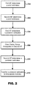
- Figure 2 shows a flow diagram of a method for determining navigation data, e.g. a PVT solution using carrier range measurements obtained by at least one GNSS receiver.
- Figure 2 is described below with reference also to Figure 1 .
- Step 200 The time update module 112 of the first Kalman filter 100 determines a priori estimates 120 of the first state vector x ⁇ k 1 ⁇ and the associated error covariance P k 1 ⁇ .
- the superscript "1" denotes the first Kalman filter 100.
- the a priori estimate of the first state vector x ⁇ k 1 ⁇ is determined using equation (1) and the a priori estimate of the covariance P k 1 ⁇ is determined using equation (2).
- Step 202 The time update module 116 of the second Kalman filter 102 determines a priori estimates 122 of the second state vector x ⁇ k 2 ⁇ and the associated error covariance P k 2 ⁇ .
- the superscript "2" denotes the second Kalman filter.
- the a priori estimates 122 are determined in the second Kalman filter 102 using equations (1) and (2).
- the a priori estimates of the first and/or second state vectors x ⁇ k 1 ⁇ , x ⁇ k 2 ⁇ are determined using measurements obtained by one or more sensors, such as inertial sensors. Inertial sensor measurements may be included in equation (1) as the control input u k -1 , along with an appropriate control input matrix B. It is noted however, that other measurements may be used as the control input u k ⁇ 1 1 , u k ⁇ 1 2 instead of or in addition to the inertial measurements. Further, one or both of the control inputs u k ⁇ 1 1 , u k ⁇ 1 2 may be set to zero if no measurements are used in the determination of the a priori estimates of the first and/or second state vectors.
- Step 204 The measurement update module 114 of the first Kalman filter 100 determines an a posteriori estimate of the first state vector x ⁇ k 1 and the associated error covariance P k 1 . As discussed above, this may be done using equations (3), (4) and (5) using the a priori estimate 120 of the first state vector x ⁇ k 1 ⁇ and the associated a priori estimate of the error covariance P k 1 ⁇ from the time update module 112, along with a first set of GNSS measurements 104, which form at least part of z k 1 and relate to a plurality of GNSS satellites.
- the first set of GNSS measurements 104 may have been obtained by one or more GNSS receivers.
- the measurement update module 114 of the first Kalman filter 100 may also receive GNSS model data 108 relating to the plurality of satellites.
- the GNSS model data 108 may be used to mitigate or remove error sources in the first set of GNSS measurements 104, for example by accounting for atmospheric corrections.
- satellite-satellite differencing techniques may be employed to mitigate or remove error sources from the first set of GNSS measurements.
- the a posteriori estimate of the first state vector comprises at least an estimate of position and an estimate of the carrier range ambiguity for each of the plurality of GNSS satellites. Estimating position in the first state vector allows the use of geometry based techniques for determining the carrier range ambiguities.
- Step 206 Carrier range ambiguity data 126, which in this case comprises the estimated carrier range ambiguities is passed from the measurement update module 114 of the first Kalman filter 100 to the measurement update module 118 of the second Kalman filter 102.
- Step 208 The measurement update module 118 of the second Kalman filter 102 determines an a posteriori estimate of the second state vector x ⁇ k 2 . As with the first Kalman filter 100, this may be done using equations (3), (4) and (5) above using the a priori estimates 122 of the second state vector x ⁇ k 2 ⁇ and the associated a priori estimate of the error covariance P k 2 ⁇ from the time update module 116, along with a second set of GNSS measurements 106, which form part of z k 2 and relate to a plurality of GNSS satellites and the carrier range ambiguity data 126 from step 206.
- the measurement update module 118 may also receive GNSS model data 110, which it may use in a similar way to the first Kalman filter 100 to correct and/or mitigate one or more GNSS error sources.
- the measurement update module 118 receives the carrier range ambiguity data 126 from the measurement update module 114 and these are added to z k 2 along with the second set of GNSS measurements 110.
- the a posteriori estimate of the second state vector may be output as PVT 124.
- Step 210 The measurement update modules 114, 118 transfer the a posteriori estimates x ⁇ k 1 , x ⁇ k 2 to the time update modules 112, 116 respectively, where they are used as x ⁇ k ⁇ 1 1 , and x ⁇ k ⁇ 1 2 for the next iteration of the Kalman filters 100, 102.
- the measurement update modules 114, 118 of the first and/or second Kalman filters 100, 102 may also receive further measurements from one or more sensors, such as a speed sensor or an odometer, that are indicative of a speed of the GNSS receiver (or a vehicle to which the apparatus is fitted).
- sensors such as a speed sensor or an odometer
- a number of revolutions of a wheel of a vehicle also sometimes known as wheel ticks
- a measurement indicative of speed in the first and/or second Kalman filters 100, 102 may be used as a measurement indicative of speed in the first and/or second Kalman filters 100, 102. If such measurements are used then they are added to the measurement vector, z k of the respective Kalman filter.
- the flow diagram shown in Figure 2 is illustrative only and that the various steps of the flow need not be undertaken in that order. It is also noted that the flow diagram of Figure 2 assumes that the first and second Kalman filters 100, 102 are being updated at the same time. However, in exemplary implementations, the first and second Kalman filters 100, 102 may update at a first update rate and a second update rate respectively and the second update rate may be greater than the first. In such cases, the measurement update module 118 of the second Kalman filter 102 uses the most recent carrier range ambiguity data 126 determined by the first Kalman filter 100.
- Figure 3 shows an exemplary apparatus for determining navigation data using carrier range measurements obtained by a GNSS receiver and relating to a plurality of GNSS satellites.
- One or more features of Figure 3 may have the same or a similar function as corresponding features of Figure 1 and these are not explained again in detail here. Where possible, such features are identified by a corresponding reference numeral to that used in Figure 1 , but beginning with a "3" instead of a "1".
- the measurement update in a Kalman filter may be undertaken in two or more steps, such that particular state variables may be determined independently.
- the apparatus of Figure 2 uses this attribute of a Kalman filter as a means for the second Kalman filter 302 to provide velocity data 328, including a velocity estimate, to the first Kalman filter 300.
- the second Kalman filter 302 determines the velocity data 328, which includes a velocity estimate and a measure of the uncertainty (e.g. an estimate of the error covariance) of the velocity estimate based on data obtained by one or more sensors 330, 332 and that is indicative of motion and/or orientation from a time update undertaken in the time update module as described above in connection with equations (1) and (2).
- the velocity data 328 is passed from the second Kalman filter to the time update module 312 of the first Kalman filter 300.
- the time update module 312 of the first Kalman filter 300 may then use the velocity estimate as a control input together with the measure of uncertainty when determining of the a priori estimate 320 of the first state vector.
- ⁇ is the time between updates.
- the first Kalman filter 300 does not need to be extended to support the integration of measurements from one or more sensors 330, 332 (e.g. inertial and/or speed sensors), as they are integrated in the second Kalman filter 302 and velocity data 328 is passed to the secondary filter.
- sensors 330, 332 e.g. inertial and/or speed sensors
- velocity data 328 is passed to the secondary filter.
- modularity is improved because improvements in the second Kalman filter 302, e.g. by using additional sensor measurements, are automatically realised in the first Kalman filter 300 without the need to implement modifications to the first Kalman filter 300.
- Figure 3 shows that the velocity data 328 is determined by the measurement update module 318 of the second Kalman filter 302 and passed to the time update module 312 of the first Kalman filter 300.
- the time update module 316 of the second Kalman filter 302 determines a priori estimates 322 of the second state vector, which may or may not use inertial sensor measurements 330 as a control input, using equation (1) above, and the associated a priori estimate of the error covariance using equation (2) above.
- the measurement update module 318 receives the a priori estimates 322 and speed sensor measurements 332 (e.g. wheel tick data) and performs a velocity measurement update based thereon and using equation 7 (copied below) to produce the velocity data 328, comprising the velocity estimate and optionally the error covariance of the velocity estimate.
- the second set of GNSS measurements 306 are not used in the velocity measurement update.
- the velocity data 328 is passed to the time update module 312 of the first Kalman filter 300.
- the time update module determines the a priori estimates 320 using equations (1) and (2), with the velocity estimate as the control input.
- the time update module 316 of the second Kalman filter 302 may transfer the velocity data 328 to the time update module 312 of the first Kalman filter 300.
- the time update module 316 determines the a priori estimates 322 using the inertial sensor measurements 330 as the control input and passes velocity data 328 from the a priori estimates 322 to the time update module 312 of the first Kalman filter 300.
- the measurement update module 314 of the first Kalman filter 300 determines the a posteriori estimate of the first state vector based on the a priori estimate 320, the first set of GNSS measurements 304 and optionally the GNSS model data 308.
- the carrier range ambiguity data 326 which in this case comprises the carrier range ambiguities for the ranging measurements for each received GNSS satellite signal, is passed to the measurement update module 318 of the second Kalman filter 302.
- the measurement update module 318 determines the a posteriori estimate of the second state vector based on the a priori estimate 322, the speed sensor measurements 332, the second set of GNSS measurements 306, the carrier range ambiguity data 326 and optionally the GNSS model data 310.
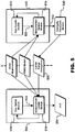
- Figure 4 shows an exemplary apparatus for determining navigation data using carrier range measurements obtained by a GNSS receiver and relating to a plurality of GNSS satellites.
- One or more features of Figure 4 may have the same or a similar function as corresponding features of Figures 1 and 3 and these are not explained again in detail here. Where possible, such features are identified by a corresponding reference numeral to that used in Figure 1 , but beginning with a "4" instead of a "1".
- first Kalman filter 400 and second Kalman filter 402 are independent and estimate independent position solutions via a "position" state in their corresponding state vectors .
- first measurement residuals the measurement residuals of the first Kalman filter
- second measurement residuals the measurement residuals of the second Kalman filter
- the time update module 416 of the second Kalman filter determines a priori estimates 422 of the second state vector, which may or may not include inertial sensor measurements, and an estimate of the covariance for each state in the second state vector.
- the time update module 416 of the second Kalman filter 402 passes an a priori estimate of one or more states from the second state vector to the measurement update module 414 of the first Kalman filter 400.
- the measurement update module 418 of the second Kalman filter 402 determines an a posteriori estimate of the second state vector based on the a priori estimates 422, the second set of GNSS measurements 406, the carrier range ambiguity data 426 previously determined by the first Kalman filter 400 and optionally the GNSS model data 410.
- the measurement update module 418 determines Kalman filter parameters 436 for the second Kalman filter 402 and passes these to the measurement update module 414 of the first Kalman filter 400.
- the Kalman filter parameters comprise the measurement matrix H, of the second Kalman filter 402, the second measurement residuals and the measurement covariance matrix R.
- the a priori estimate of one or more states of the second state vector and the Kalman filter parameters 436 form measurement residual data 438.
- the estimated first measurement residuals may be substituted into equation (3) above by the measurement update module 414 when determining the a posteriori estimate of the first state vector.
- the arrangement shown in Figure 4 reduces the amount of data that is required to be accessed by the first Kalman filter 400.
- the first Kalman filter 400 does not need access to GNSS measurements or GNSS model data.
- the a posteriori estimate of the first Kalman filter 400 is based on GNSS measurements, as those GNSS measurements are used to determine the second measurement residuals, which in turn are used to determine the first measurement residuals.
- the first set of GNSS measurements can be considered the same as the second set of GNSS measurements.
- Figure 5 shows an exemplary apparatus for determining navigation data using carrier range measurements obtained by a GNSS receiver and relating to a plurality of GNSS satellites.
- One or more features of Figure 5 may have the same or a similar function as corresponding features of Figures 1 , 3 and 4 and these are not explained again in detail here. Where possible, such features are identified by a corresponding reference numeral to that used in Figure 1 , but beginning with a "5" instead of a "1".
- the apparatus of Figure 5 includes an ambiguity resolution module 540.
- the ambiguity resolution module 540 may be included in any apparatus disclosed herein, specifically those shown in Figures 1 , 3 and 4 .
- Figure 5 shows the ambiguity resolution module 540 used with the apparatus of Figure 1 , but this is exemplary only.
- the ambiguity resolution module 540 receives float carrier range ambiguity values 542 from the measurement update module 514, which estimates them as part of the a posteriori estimate of the second state vector.
- the ambiguity resolution module resolves the carrier range ambiguity values to integers using any known technique, such as the LAMBDA technique.
- the resolved integer carrier range ambiguity values are passed to the measurement update module 518 of the second Kalman filter as the carrier range ambiguity data 526.
- Exemplary methods and apparatus may include multiple Kalman filters configured to determine an a posteriori estimate of a state vector including carrier range ambiguity values. That is, exemplary methods and apparatus may comprise a plurality of first Kalman filters 100, 300, 400, each implementing a different state model and/or determining the a posteriori estimate of the state vector based on different sets of GNSS measurements.
- a separate Kalman filter can be used to determine carrier range ambiguity values for each of a plurality of GNSS constellations.
- separate Kalman filters can be configured to use different estimation strategies when estimating the carrier range ambiguity values. For example, one Kalman filter may use an aggressive estimation strategy and another may use a more conservative estimation strategy.
- the measurement update module 118, 318, 418 etc. of the second Kalman filter 102, 302, 402 etc. may receive carrier range ambiguity data based on all of the different estimations of the carrier range ambiguity.
- the measurement update module of the second Kalman filter may compare all the estimates of carrier range ambiguities for consistency and not use any that appear incorrect.
- the measurement update module of the second Kalman filter may weight each of the estimations of carrier range ambiguities when using them to determine the a posteriori estimate of the second state vector.
- a computer program may be configured to provide any of the above described methods.
- the computer program may be provided on a computer readable medium.
- the computer program may be a computer program product.
- the product may comprise a non-transitory computer usable storage medium.
- the computer program product may have computer-readable program code embodied in the medium configured to perform the method.
- the computer program product may be configured to cause at least one processor to perform some or all of the method.
- These computer program instructions may be provided to a processor circuit of a general purpose computer circuit, special purpose computer circuit, and/or other programmable data processing circuit to produce a machine, such that the instructions, which execute via the processor of the computer and/or other programmable data processing apparatus, transform and control transistors, values stored in memory locations, and other hardware components within such circuitry to implement the functions/acts specified in the block diagrams and/or flowchart block or blocks, and thereby create means (functionality) and/or structure for implementing the functions/acts specified in the block diagrams and/or flowchart block(s).
- Computer program instructions may also be stored in a computer-readable medium that can direct a computer or other programmable data processing apparatus to function in a particular manner, such that the instructions stored in the computer-readable medium produce an article of manufacture including instructions which implement the functions/acts specified in the block diagrams and/or flowchart block or blocks.
- a tangible, non-transitory computer-readable medium may include an electronic, magnetic, optical, electromagnetic, or semiconductor data storage system, apparatus, or device. More specific examples of the computer-readable medium would include the following: a portable computer diskette, a random access memory (RAM) circuit, a read-only memory (ROM) circuit, an erasable programmable read-only memory (EPROM or Flash memory) circuit, a portable compact disc read-only memory (CD-ROM), and a portable digital video disc read-only memory (DVD/Blu-ray).
- RAM random access memory
- ROM read-only memory
- EPROM or Flash memory erasable programmable read-only memory
- CD-ROM compact disc read-only memory
- DVD/Blu-ray portable digital video disc read-only memory
- the computer program instructions may also be loaded onto a computer and/or other programmable data processing apparatus to cause a series of operational steps to be performed on the computer and/or other programmable apparatus to produce a computer-implemented process such that the instructions which execute on the computer or other programmable apparatus provide steps for implementing the functions/acts specified in the block diagrams and/or flowchart block or blocks.
- the invention may be embodied in hardware and/or in software (including firmware, resident software, micro-code, etc.) that runs on a processor, which may collectively be referred to as "circuitry,” "a module” or variants thereof.
Claims (19)
- Vorrichtung zum Bestimmen von Navigationsdaten (124) unter Verwendung von Trägerbereichsmessungen durch einen GNSS-Empfänger für eine Mehrzahl von GNSS-Satelliten, wobei die Vorrichtung umfasst:einen ersten Kalmanfilter (100), der konfiguriert ist zum Ermitteln einer a-posteriori-Schätzung eines ersten Zustandsvektors basierend zumindest teilweise auf einem ersten Satz von GNSS-Messungen (104) durch den und/oder einen weiteren GNSS-Empfänger und einer a-priori-Schätzung des ersten Zustandsvektors, wobei der erste Zustandsvektor Trägerbereichsmehrdeutigkeitswerte in Bezug auf die Vielzahl von GNSS-Satelliten und eine Position des und/oder des weiteren GNSS-Empfängers umfasst; undeinen zweiten Kalmanfilter (102), der konfiguriert ist zum Ermitteln einer a-posteriori-Schätzung eines zweiten Zustandsvektors, der die Navigationsdaten (124) basierend zumindest teilweise auf einem zweiten Satz von GNSS-Messungen (106), die durch den und/oder einen weiteren GNSS-Empfänger erhalten wurden, einer a-priori-Schätzung des zweiten Zustandsvektors und Trägerbereichsmehrdeutigkeitsdaten (126) basierend auf den Trägerbereichsmehrdeutigkeitswerten, die bei der a-posteriori-Schätzung des ersten Zustandsvektors bestimmt wurden, umfasst.
- Vorrichtung nach Anspruch 1, wobei der erste Kalmanfilter konfiguriert ist zum Bestimmen der a-priori-Schätzung des ersten Zustandsvektors basierend auf zumindest einer von einer Geschwindigkeitsschätzung für den und/oder den weiteren GNSS-Empfänger und ein gewisses Maß an Unsicherheit in Bezug auf die Geschwindigkeitsschätzung, jeweils bestimmt durch den zweiten Kaimanfilter.
- Vorrichtung nach Anspruch 2, wobei der zweite Kalmanfilter konfiguriert ist zum Bestimmen der Geschwindigkeitsschätzung und/oder des Maßes an Unsicherheit basierend auf den Daten, die durch einen oder mehrere Sensoren erhalten wurden und die eine Bewegung und/oder Orientierung des und/oder des weiteren GNSS-Empfängers anzeigen.
- Vorrichtung nach Anspruch 2 oder 3, wobei der zweite Kalmanfilter konfiguriert ist zum Bestimmen der Geschwindigkeitsschätzung und/oder des Maßes an Unsicherheit basierend auf der a-priori-Schätzung des zweiten Zustandsvektors und einer oder mehreren Messungen, die durch einen oder mehrere Sensoren erhalten wurden und eine Geschwindigkeit des oder des weiteren GNSS-Empfängers anzeigen.
- Vorrichtung nach einem der vorhergehenden Ansprüche, wobei, wenn die a-posteriori-Schätzung des ersten Zustandsvektors bestimmt wird, der erste Kalmanfilter konfiguriert ist, um geschätzte erste Messreste für den ersten Kalmanflter basierend auf zweiten Messresten für den zweiten Kalmanfilter zu bestimmen.
- Vorrichtung nach Anspruch 5, wobei der erste Kalmanfilter ferner konfiguriert ist zum Schätzen der ersten Messreste basierend auf Kaimanfilterparametern des zweiten Kaimanfilters, mindestens eines Teils der a-priori-Schätzung des zweiten Zustandsvektors und mindestens eines Teils der a-priori-Schätzung des ersten Zustandsvektors.
- Vorrichtung nach einem der vorhergehenden Ansprüche, wobei der erste Kalmanfilter konfiguriert ist zum Bestimmen der a-posteriori-Schätzung des ersten Zustandsvektors mit einer ersten Aktualisierungsrate und wobei der zweite Kalmanfilter konfiguriert ist, zum Bestimmen der a-posteriori-Schätzung des zweiten Zustandsvektors mit einer zweiten Aktualisierungsrate.
- Vorrichtung nach Anspruch 7, wobei die zweite Aktualisierungsrate größer ist als die erste Aktualisierungsrate.
- Vorrichtung nach einem der vorhergehenden Ansprüche, wobei der zweite Kalmanfilter konfiguriert ist zum Bestimmen der a-priori-Schätzung des zweiten Zustandsvektors basierend auf Trägheitsmessungen, die durch einen oder mehrere Trägheitssensoren erhalten wurden und eine Beschleunigung und/oder Winkeldrehgeschwindigkeit des oder des weiteren GNSS-Empfängers anzeigen.
- Vorrichtung nach einem der vorhergehenden Ansprüche, wobei einer der ersten oder zweiten Sätze von GNSS-Messungen zumindest eine GNSS-Messung umfasst, die nicht in dem anderen der ersten oder zweiten Sätze von GNSS-Messungen enthalten ist.
- Vorrichtung nach einem der vorhergehenden Ansprüche, umfassend zwei GNSS-Empfänger, und wobei der erste und der zweite Satz von GNSS-Messungen jeweils GNSS Messungen umfassen, die durch die beiden GNSS-Empfänger erhalten wurden.
- Vorrichtung nach einem der vorhergehenden Ansprüche, ferner umfassend erste und zweite Prozessoren, wobei der erste Prozessor konfiguriert ist zum Implementieren des ersten Kalmanfilters und der zweite Prozessor konfiguriert ist zum Implementieren des zweiten Kaimanfilters.
- Vorrichtung nach einem der vorhergehenden Ansprüche, ferner umfassend ein Mehrdeutigkeitsauflösungsmodul, das konfiguriert ist zum Auflösen der in der a-posteriori-Schätzung des ersten Zustandsvektors bestimmten Trägerbereichsmehrdeutigkeitswerte auf ganze Zahlen, und wobei die Trägerbereichsmehrdeutigkeitsdaten die aufgelösten ganzzahligen Trägerbereichsmehrdeutigkeitswerte umfassen.
- Vorrichtung nach einem der vorhergehenden Ansprüche, wobei der erste Zustandsvektor atmosphärische Korrekturwerte in Bezug auf die Vielzahl von GNSS Satelliten umfasst.
- Vorrichtung nach Anspruch 14, wobei die Trägerbereichsmehrdeutigkeitsdaten die Trägerbereichsmehrdeutigkeitswerte und die atmosphärischen Korrekturwerte umfassen und wobei der zweite Kalmanfilter konfiguriert ist, um die Trägerbereichsmehrdeutigkeitswerte basierend auf den atmosphärischen Korrekturwerten einzustellen.
- Vorrichtung nach Anspruch 14, wobei der erste Kalmanfilter konfiguriert ist, um die Trägerbereichsmehrdeutigkeitswerte basierend auf den atmosphärischen Korrekturwerten einzustellen, und wobei die Trägerbereichsmehrdeutigkeitsdaten die eingestellten Trägerbereichsmehrdeutigkeitswerte umfassen.
- Vorrichtung nach einem der vorhergehenden Ansprüche, ferner umfassend einen oder mehrere weitere Kalmanfilter, die konfiguriert sind zum Bestimmen einer a-posteriori-Schätzung eines oder mehrerer weiterer Zustandsvektoren basierend zumindest teilweise auf weiteren GNSS-Messungen durch den und/oder einen weiteren GNSS-Empfänger und eine oder mehrere a-priori-Schätzungen des einen oder der mehreren weiteren Zustandsvektoren, wobei der eine oder die mehreren weiteren Zustandsvektoren ferner weitere Trägerbereichsmehrdeutigkeitswerte in Bezug auf die Vielzahl von GNSS-Satelliten umfassen,
und wobei die Trägerbereichsmehrdeutigkeitsdaten auch auf den weiteren Trägerbereichsmehrdeutigkeitswerten basieren. - Verfahren zum Bestimmen von Navigationsdaten unter Verwendung von Trägerbereichsmessungen durch einen GNSS-Empfänger für eine Mehrzahl von GNSS-Satelliten, wobei das Verfahren umfasst:Bestimmen, durch einen ersten Kalmanfilter, einer a-posteriori-Schätzung eines ersten Zustandsvektors, zumindest teilweise basierend auf einem ersten Satz von GNSS-Messungen, die durch den und/oder einen weiteren GNSS-Empfänger erhalten wurden, und einer a-priori-Schätzung des ersten Zustandsvektors, wobei der erste Zustandsvektor Trägerbereichsmehrdeutigkeitswerte in Bezug auf die mehreren GNSS-Satelliten und eine Position des und/oder des weiteren GNSS-Empfängers umfasst; undBestimmen, durch einen zweiten Kalmanfilter, einer a-posteriori-Schätzung eines zweiten Zustandsvektors, der die Navigationsdaten umfasst, zumindest teilweise basierend auf einem zweiten Satz von GNSS-Messungen, die durch den und/oder einen weiteren GNSS-Empfänger erhalten wurden, einer a-priori-Schätzung des zweiten Zustandsvektors und Trägerbereichsmehrdeutigkeitsdaten basierend auf den Trägerbereichsmehrdeutigkeitswerten, die in der a-posteriori-Schätzung des ersten Zustandsvektors bestimmt wurden.
- Computerprogramm, umfassend Anweisungen, die bei Ausführung auf mindestens einem Prozessor den mindestens einen Prozessor dazu veranlassen, das Verfahren nach Anspruch 18 auszuführen.
Priority Applications (4)
| Application Number | Priority Date | Filing Date | Title |
|---|---|---|---|
| EP16206872.0A EP3339908B1 (de) | 2016-12-23 | 2016-12-23 | Verteilte kalman-filter-architektur für die bestimmung der phasenmehrdeutigkeiten |
| JP2017182789A JP6907083B2 (ja) | 2016-12-23 | 2017-09-22 | 搬送波伝播距離のアンビギュイティ推定用分散カルマン・フィルタ・アーキテクチャ |
| US15/784,452 US10564296B2 (en) | 2016-12-23 | 2017-10-16 | Distributed kalman filter architecture for carrier range ambiguity estimation |
| CN201710960851.4A CN108241161B (zh) | 2016-12-23 | 2017-10-16 | 用于载波范围模糊度估计的分布式卡尔曼滤波器架构 |
Applications Claiming Priority (1)
| Application Number | Priority Date | Filing Date | Title |
|---|---|---|---|
| EP16206872.0A EP3339908B1 (de) | 2016-12-23 | 2016-12-23 | Verteilte kalman-filter-architektur für die bestimmung der phasenmehrdeutigkeiten |
Publications (2)
| Publication Number | Publication Date |
|---|---|
| EP3339908A1 EP3339908A1 (de) | 2018-06-27 |
| EP3339908B1 true EP3339908B1 (de) | 2019-10-02 |
Family
ID=57609804
Family Applications (1)
| Application Number | Title | Priority Date | Filing Date |
|---|---|---|---|
| EP16206872.0A Active EP3339908B1 (de) | 2016-12-23 | 2016-12-23 | Verteilte kalman-filter-architektur für die bestimmung der phasenmehrdeutigkeiten |
Country Status (4)
| Country | Link |
|---|---|
| US (1) | US10564296B2 (de) |
| EP (1) | EP3339908B1 (de) |
| JP (1) | JP6907083B2 (de) |
| CN (1) | CN108241161B (de) |
Families Citing this family (14)
| Publication number | Priority date | Publication date | Assignee | Title |
|---|---|---|---|---|
| CN106291645B (zh) * | 2016-07-19 | 2018-08-21 | 东南大学 | 适于高维gnss/ins深耦合的容积卡尔曼滤波方法 |
| CN110865398B (zh) | 2018-08-27 | 2022-03-22 | 腾讯大地通途(北京)科技有限公司 | 定位数据的处理方法及处理装置、终端设备和存储介质 |
| US10871579B2 (en) * | 2018-11-16 | 2020-12-22 | Swift Navigation, Inc. | System and method for satellite positioning |
| GB2579414B (en) * | 2018-11-30 | 2021-11-17 | Thales Holdings Uk Plc | Method and apparatus for determining a position of a vehicle |
| US11119187B2 (en) * | 2019-02-19 | 2021-09-14 | GM Global Technology Operations LLC | Resolution of doppler ambiguity in a radar system through tracking |
| CN114430808A (zh) * | 2019-06-06 | 2022-05-03 | 星盟国际有限公司 | 变化电离层延迟下的单历元伪距定位 |
| CN110824522B (zh) * | 2019-11-07 | 2021-11-23 | 广东星舆科技有限公司 | 双差模糊度的约束方法、存储介质和装置 |
| US11016199B1 (en) | 2019-12-11 | 2021-05-25 | Swift Navigation, Inc. | System and method for validating GNSS ambiguities |
| CN111239787B (zh) * | 2020-02-28 | 2021-02-02 | 同济大学 | 一种集群自主协同中的gnss动态卡尔曼滤波方法 |
| DE102020213769A1 (de) * | 2020-11-02 | 2022-05-05 | Robert Bosch Gesellschaft mit beschränkter Haftung | Verfahren zum Auswerten mindestens eines GNSS-Satellitensignals mit Mehrdeutigkeitsauflösung |
| CN112747742B (zh) * | 2020-12-22 | 2022-10-14 | 上海交通大学 | 一种基于卡尔曼滤波的终端位置自适应更新方法 |
| CN114966786A (zh) | 2021-02-24 | 2022-08-30 | 霍尼韦尔国际公司 | 用于dfmc gnss 模糊度解算的系统和方法 |
| EP4119988A1 (de) * | 2021-07-16 | 2023-01-18 | u-blox AG | Gnss-positionierung mit fixierung von trägerbereichsambiguitäten |
| CN113706854B (zh) * | 2021-08-20 | 2023-03-07 | 北京科技大学 | 一种智能车联网中的车辆协作定位方法 |
Family Cites Families (22)
| Publication number | Priority date | Publication date | Assignee | Title |
|---|---|---|---|---|
| AU642638B2 (en) * | 1989-12-11 | 1993-10-28 | Caterpillar Inc. | Integrated vehicle positioning and navigation system, apparatus and method |
| US5451964A (en) * | 1994-07-29 | 1995-09-19 | Del Norte Technology, Inc. | Method and system for resolving double difference GPS carrier phase integer ambiguity utilizing decentralized Kalman filters |
| US5991691A (en) * | 1997-02-20 | 1999-11-23 | Raytheon Aircraft Corporation | System and method for determining high accuracy relative position solutions between two moving platforms |
| US6246960B1 (en) * | 1998-11-06 | 2001-06-12 | Ching-Fang Lin | Enhanced integrated positioning method and system thereof for vehicle |
| JP4116792B2 (ja) * | 2001-12-19 | 2008-07-09 | 古野電気株式会社 | キャリア位相相対測位装置 |
| US9002565B2 (en) * | 2003-03-20 | 2015-04-07 | Agjunction Llc | GNSS and optical guidance and machine control |
| JP2005164395A (ja) * | 2003-12-02 | 2005-06-23 | Toyota Motor Corp | 搬送波位相式gps測位装置及び方法 |
| CN101287999B (zh) * | 2005-10-03 | 2011-11-02 | 天宝导航有限公司 | 带有时钟差建模的多gnss信号处理 |
| US8587475B2 (en) * | 2008-10-06 | 2013-11-19 | Trimble Navigation Limited | Position estimation methods and apparatus |
| JP5439826B2 (ja) * | 2009-01-26 | 2014-03-12 | セイコーエプソン株式会社 | 位置算出方法及び位置算出装置 |
| DE112010003672T5 (de) * | 2009-09-19 | 2012-12-13 | Trimble Navigation Ltd. | GNSS-Signalverarbeitung mit Rover-Mehrdeutigkeitsfestlegen |
| DE112011100528T5 (de) * | 2010-02-14 | 2012-12-06 | Trimble Navigation Limited | GNSS-Signalverarbeitungmit regionaler Augmentationsnachricht |
| RU2012152265A (ru) * | 2011-06-28 | 2014-10-27 | Владимир Викторович Вейцель | Методы и аппаратура определения направления движения приемника гнсс |
| EP2634593B1 (de) * | 2012-03-02 | 2016-11-09 | U-blox AG | Positionierung mit Hilfe eines lokalen Wellenausbreitungsmodells |
| JP5794646B2 (ja) * | 2013-12-27 | 2015-10-14 | 日本電気株式会社 | 衛星測位システム、測位端末、測位方法、及びプログラム |
| CN103777220B (zh) * | 2014-01-17 | 2016-04-27 | 西安交通大学 | 基于光纤陀螺、速度传感器和gps的实时精确位姿估计方法 |
| CN105510942A (zh) * | 2015-12-27 | 2016-04-20 | 哈尔滨米米米业科技有限公司 | 一种基于卡尔曼滤波的gps单点定位系统 |
| US10203417B2 (en) * | 2016-01-25 | 2019-02-12 | Topcon Positioning Systems, Inc. | Methods and apparatus for estimating motion parameters of GNSS receiver |
| CN105806338B (zh) * | 2016-03-17 | 2018-10-19 | 武汉际上导航科技有限公司 | 基于三向卡尔曼滤波平滑器的gnss/ins组合定位定向算法 |
| CN105929430B (zh) * | 2016-07-14 | 2018-09-21 | 天津市勘察院 | 一种gnss零基线参考站间模糊度快速固定方法 |
| US10274607B2 (en) * | 2016-09-13 | 2019-04-30 | Qualcomm Incorporated | Fast recovery from incorrect carrier phase integer locking |
| CN108680942B (zh) * | 2018-09-07 | 2018-12-07 | 湖南天羿领航科技有限公司 | 一种惯性/多天线gnss组合导航方法及装置 |
-
2016
- 2016-12-23 EP EP16206872.0A patent/EP3339908B1/de active Active
-
2017
- 2017-09-22 JP JP2017182789A patent/JP6907083B2/ja active Active
- 2017-10-16 CN CN201710960851.4A patent/CN108241161B/zh active Active
- 2017-10-16 US US15/784,452 patent/US10564296B2/en active Active
Non-Patent Citations (1)
| Title |
|---|
| None * |
Also Published As
| Publication number | Publication date |
|---|---|
| CN108241161B (zh) | 2023-03-10 |
| JP2018136298A (ja) | 2018-08-30 |
| CN108241161A (zh) | 2018-07-03 |
| US10564296B2 (en) | 2020-02-18 |
| EP3339908A1 (de) | 2018-06-27 |
| US20180180743A1 (en) | 2018-06-28 |
| JP6907083B2 (ja) | 2021-07-21 |
Similar Documents
| Publication | Publication Date | Title |
|---|---|---|
| EP3339908B1 (de) | Verteilte kalman-filter-architektur für die bestimmung der phasenmehrdeutigkeiten | |
| US5543804A (en) | Navagation apparatus with improved attitude determination | |
| JP5483735B2 (ja) | 衛星航法装置 | |
| EP2380036B1 (de) | Navigationsempfänger und verfahren zur kombinierten verwendung eines rtk-standardsystems und carrier-phase-dgps | |
| EP1704421B1 (de) | Verfahren zur kombinierten verwendung eines lokalen rtk-systems und eines regionalen grossflächigen oder globalen trägerphasen-positionsbestimmungssystems | |
| US7576690B2 (en) | Position determination with reference data outage | |
| CN108120994B (zh) | 一种基于星载gnss的geo卫星实时定轨方法 | |
| TWI418833B (zh) | 處理衛星信號的方法及系統 | |
| JP7329814B2 (ja) | 測位装置、測位方法、測位プログラム、測位プログラム記憶媒体、アプリケーション装置、および、測位システム | |
| WO2013080183A9 (en) | A quasi tightly coupled gnss-ins integration process | |
| US20230314626A1 (en) | Method for determining a state parameter of a receiver and an apparatus for performing such a method | |
| CN110221325B (zh) | 一种用于伪距差分定位的误差修正方法及装置 | |
| US20060015250A1 (en) | GPS navigation with integrated phase track filter | |
| JP4108738B2 (ja) | 測位装置 | |
| EP3631515B1 (de) | Verfahren zur schätzung einer position einer mobilen vorrichtung unter verwendung von gnss-signalen | |
| US20240118434A1 (en) | Positioning apparatus, computer readable medium, and positioning method | |
| CN115362349A (zh) | 导航方法与系统 | |
| EP3748401A1 (de) | System und verfahren zur positionsbestimmung eines stationären gnss-empfängers unter verwendung eines verteilten zeitsignals | |
| CN113179480A (zh) | 用于定位车辆的方法和设备 | |
| EP4231055A1 (de) | Gnss-positionierung basierend auf änderungen im trägerbereich | |
| CN115980803B (zh) | 基于双频码伪距和载波相位观测量进行伪距平滑的方法 | |
| US20230194731A1 (en) | Calculating a position of one device relative to another | |
| Farooq et al. | Design of a Differential Vector Phase Locked Loop for Single Frequency RTK Receivers | |
| RU2325667C1 (ru) | Способ определения вектора состояния космического аппарата по сигналам космических навигационных систем | |
| WO2024013380A1 (en) | Method and apparatus for performing motion-compensated signal processing |
Legal Events
| Date | Code | Title | Description |
|---|---|---|---|
| PUAI | Public reference made under article 153(3) epc to a published international application that has entered the european phase |
Free format text: ORIGINAL CODE: 0009012 |
|
| STAA | Information on the status of an ep patent application or granted ep patent |
Free format text: STATUS: THE APPLICATION HAS BEEN PUBLISHED |
|
| AK | Designated contracting states |
Kind code of ref document: A1 Designated state(s): AL AT BE BG CH CY CZ DE DK EE ES FI FR GB GR HR HU IE IS IT LI LT LU LV MC MK MT NL NO PL PT RO RS SE SI SK SM TR |
|
| AX | Request for extension of the european patent |
Extension state: BA ME |
|
| STAA | Information on the status of an ep patent application or granted ep patent |
Free format text: STATUS: REQUEST FOR EXAMINATION WAS MADE |
|
| 17P | Request for examination filed |
Effective date: 20180518 |
|
| RBV | Designated contracting states (corrected) |
Designated state(s): AL AT BE BG CH CY CZ DE DK EE ES FI FR GB GR HR HU IE IS IT LI LT LU LV MC MK MT NL NO PL PT RO RS SE SI SK SM TR |
|
| REG | Reference to a national code |
Ref country code: DE Ref legal event code: R079 Ref document number: 602016021604 Country of ref document: DE Free format text: PREVIOUS MAIN CLASS: G01S0019440000 Ipc: G01S0019130000 |
|
| GRAP | Despatch of communication of intention to grant a patent |
Free format text: ORIGINAL CODE: EPIDOSNIGR1 |
|
| STAA | Information on the status of an ep patent application or granted ep patent |
Free format text: STATUS: GRANT OF PATENT IS INTENDED |
|
| RIC1 | Information provided on ipc code assigned before grant |
Ipc: G01S 19/13 20100101AFI20190627BHEP Ipc: G01S 19/44 20100101ALI20190627BHEP |
|
| GRAS | Grant fee paid |
Free format text: ORIGINAL CODE: EPIDOSNIGR3 |
|
| INTG | Intention to grant announced |
Effective date: 20190724 |
|
| GRAA | (expected) grant |
Free format text: ORIGINAL CODE: 0009210 |
|
| STAA | Information on the status of an ep patent application or granted ep patent |
Free format text: STATUS: THE PATENT HAS BEEN GRANTED |
|
| AK | Designated contracting states |
Kind code of ref document: B1 Designated state(s): AL AT BE BG CH CY CZ DE DK EE ES FI FR GB GR HR HU IE IS IT LI LT LU LV MC MK MT NL NO PL PT RO RS SE SI SK SM TR |
|
| REG | Reference to a national code |
Ref country code: GB Ref legal event code: FG4D |
|
| REG | Reference to a national code |
Ref country code: CH Ref legal event code: EP Ref country code: AT Ref legal event code: REF Ref document number: 1186817 Country of ref document: AT Kind code of ref document: T Effective date: 20191015 |
|
| REG | Reference to a national code |
Ref country code: DE Ref legal event code: R096 Ref document number: 602016021604 Country of ref document: DE |
|
| REG | Reference to a national code |
Ref country code: IE Ref legal event code: FG4D |
|
| REG | Reference to a national code |
Ref country code: CH Ref legal event code: PLX |
|
| PG25 | Lapsed in a contracting state [announced via postgrant information from national office to epo] |
Ref country code: LI Free format text: LAPSE BECAUSE OF THE APPLICANT RENOUNCES Effective date: 20191002 Ref country code: CH Free format text: LAPSE BECAUSE OF THE APPLICANT RENOUNCES Effective date: 20191002 |
|
| REG | Reference to a national code |
Ref country code: NL Ref legal event code: MP Effective date: 20191002 |
|
| REG | Reference to a national code |
Ref country code: LT Ref legal event code: MG4D |
|
| REG | Reference to a national code |
Ref country code: AT Ref legal event code: MK05 Ref document number: 1186817 Country of ref document: AT Kind code of ref document: T Effective date: 20191002 |
|
| PG25 | Lapsed in a contracting state [announced via postgrant information from national office to epo] |
Ref country code: FI Free format text: LAPSE BECAUSE OF FAILURE TO SUBMIT A TRANSLATION OF THE DESCRIPTION OR TO PAY THE FEE WITHIN THE PRESCRIBED TIME-LIMIT Effective date: 20191002 Ref country code: BG Free format text: LAPSE BECAUSE OF FAILURE TO SUBMIT A TRANSLATION OF THE DESCRIPTION OR TO PAY THE FEE WITHIN THE PRESCRIBED TIME-LIMIT Effective date: 20200102 Ref country code: PT Free format text: LAPSE BECAUSE OF FAILURE TO SUBMIT A TRANSLATION OF THE DESCRIPTION OR TO PAY THE FEE WITHIN THE PRESCRIBED TIME-LIMIT Effective date: 20200203 Ref country code: LT Free format text: LAPSE BECAUSE OF FAILURE TO SUBMIT A TRANSLATION OF THE DESCRIPTION OR TO PAY THE FEE WITHIN THE PRESCRIBED TIME-LIMIT Effective date: 20191002 Ref country code: NO Free format text: LAPSE BECAUSE OF FAILURE TO SUBMIT A TRANSLATION OF THE DESCRIPTION OR TO PAY THE FEE WITHIN THE PRESCRIBED TIME-LIMIT Effective date: 20200102 Ref country code: PL Free format text: LAPSE BECAUSE OF FAILURE TO SUBMIT A TRANSLATION OF THE DESCRIPTION OR TO PAY THE FEE WITHIN THE PRESCRIBED TIME-LIMIT Effective date: 20191002 Ref country code: GR Free format text: LAPSE BECAUSE OF FAILURE TO SUBMIT A TRANSLATION OF THE DESCRIPTION OR TO PAY THE FEE WITHIN THE PRESCRIBED TIME-LIMIT Effective date: 20200103 Ref country code: ES Free format text: LAPSE BECAUSE OF FAILURE TO SUBMIT A TRANSLATION OF THE DESCRIPTION OR TO PAY THE FEE WITHIN THE PRESCRIBED TIME-LIMIT Effective date: 20191002 Ref country code: SE Free format text: LAPSE BECAUSE OF FAILURE TO SUBMIT A TRANSLATION OF THE DESCRIPTION OR TO PAY THE FEE WITHIN THE PRESCRIBED TIME-LIMIT Effective date: 20191002 Ref country code: LV Free format text: LAPSE BECAUSE OF FAILURE TO SUBMIT A TRANSLATION OF THE DESCRIPTION OR TO PAY THE FEE WITHIN THE PRESCRIBED TIME-LIMIT Effective date: 20191002 Ref country code: NL Free format text: LAPSE BECAUSE OF FAILURE TO SUBMIT A TRANSLATION OF THE DESCRIPTION OR TO PAY THE FEE WITHIN THE PRESCRIBED TIME-LIMIT Effective date: 20191002 Ref country code: AT Free format text: LAPSE BECAUSE OF FAILURE TO SUBMIT A TRANSLATION OF THE DESCRIPTION OR TO PAY THE FEE WITHIN THE PRESCRIBED TIME-LIMIT Effective date: 20191002 |
|
| PG25 | Lapsed in a contracting state [announced via postgrant information from national office to epo] |
Ref country code: CZ Free format text: LAPSE BECAUSE OF FAILURE TO SUBMIT A TRANSLATION OF THE DESCRIPTION OR TO PAY THE FEE WITHIN THE PRESCRIBED TIME-LIMIT Effective date: 20191002 Ref country code: IS Free format text: LAPSE BECAUSE OF FAILURE TO SUBMIT A TRANSLATION OF THE DESCRIPTION OR TO PAY THE FEE WITHIN THE PRESCRIBED TIME-LIMIT Effective date: 20200224 Ref country code: RS Free format text: LAPSE BECAUSE OF FAILURE TO SUBMIT A TRANSLATION OF THE DESCRIPTION OR TO PAY THE FEE WITHIN THE PRESCRIBED TIME-LIMIT Effective date: 20191002 Ref country code: HR Free format text: LAPSE BECAUSE OF FAILURE TO SUBMIT A TRANSLATION OF THE DESCRIPTION OR TO PAY THE FEE WITHIN THE PRESCRIBED TIME-LIMIT Effective date: 20191002 |
|
| PG25 | Lapsed in a contracting state [announced via postgrant information from national office to epo] |
Ref country code: AL Free format text: LAPSE BECAUSE OF FAILURE TO SUBMIT A TRANSLATION OF THE DESCRIPTION OR TO PAY THE FEE WITHIN THE PRESCRIBED TIME-LIMIT Effective date: 20191002 |
|
| REG | Reference to a national code |
Ref country code: DE Ref legal event code: R097 Ref document number: 602016021604 Country of ref document: DE |
|
| PG2D | Information on lapse in contracting state deleted |
Ref country code: IS |
|
| PG25 | Lapsed in a contracting state [announced via postgrant information from national office to epo] |
Ref country code: EE Free format text: LAPSE BECAUSE OF FAILURE TO SUBMIT A TRANSLATION OF THE DESCRIPTION OR TO PAY THE FEE WITHIN THE PRESCRIBED TIME-LIMIT Effective date: 20191002 Ref country code: DK Free format text: LAPSE BECAUSE OF FAILURE TO SUBMIT A TRANSLATION OF THE DESCRIPTION OR TO PAY THE FEE WITHIN THE PRESCRIBED TIME-LIMIT Effective date: 20191002 Ref country code: RO Free format text: LAPSE BECAUSE OF FAILURE TO SUBMIT A TRANSLATION OF THE DESCRIPTION OR TO PAY THE FEE WITHIN THE PRESCRIBED TIME-LIMIT Effective date: 20191002 Ref country code: IS Free format text: LAPSE BECAUSE OF FAILURE TO SUBMIT A TRANSLATION OF THE DESCRIPTION OR TO PAY THE FEE WITHIN THE PRESCRIBED TIME-LIMIT Effective date: 20200202 |
|
| PLBE | No opposition filed within time limit |
Free format text: ORIGINAL CODE: 0009261 |
|
| STAA | Information on the status of an ep patent application or granted ep patent |
Free format text: STATUS: NO OPPOSITION FILED WITHIN TIME LIMIT |
|
| REG | Reference to a national code |
Ref country code: BE Ref legal event code: MM Effective date: 20191231 |
|
| PG25 | Lapsed in a contracting state [announced via postgrant information from national office to epo] |
Ref country code: MC Free format text: LAPSE BECAUSE OF FAILURE TO SUBMIT A TRANSLATION OF THE DESCRIPTION OR TO PAY THE FEE WITHIN THE PRESCRIBED TIME-LIMIT Effective date: 20191002 Ref country code: IT Free format text: LAPSE BECAUSE OF FAILURE TO SUBMIT A TRANSLATION OF THE DESCRIPTION OR TO PAY THE FEE WITHIN THE PRESCRIBED TIME-LIMIT Effective date: 20191002 Ref country code: SM Free format text: LAPSE BECAUSE OF FAILURE TO SUBMIT A TRANSLATION OF THE DESCRIPTION OR TO PAY THE FEE WITHIN THE PRESCRIBED TIME-LIMIT Effective date: 20191002 Ref country code: SK Free format text: LAPSE BECAUSE OF FAILURE TO SUBMIT A TRANSLATION OF THE DESCRIPTION OR TO PAY THE FEE WITHIN THE PRESCRIBED TIME-LIMIT Effective date: 20191002 |
|
| 26N | No opposition filed |
Effective date: 20200703 |
|
| PG25 | Lapsed in a contracting state [announced via postgrant information from national office to epo] |
Ref country code: LU Free format text: LAPSE BECAUSE OF NON-PAYMENT OF DUE FEES Effective date: 20191223 Ref country code: IE Free format text: LAPSE BECAUSE OF NON-PAYMENT OF DUE FEES Effective date: 20191223 |
|
| PG25 | Lapsed in a contracting state [announced via postgrant information from national office to epo] |
Ref country code: SI Free format text: LAPSE BECAUSE OF FAILURE TO SUBMIT A TRANSLATION OF THE DESCRIPTION OR TO PAY THE FEE WITHIN THE PRESCRIBED TIME-LIMIT Effective date: 20191002 Ref country code: BE Free format text: LAPSE BECAUSE OF NON-PAYMENT OF DUE FEES Effective date: 20191231 |
|
| PG25 | Lapsed in a contracting state [announced via postgrant information from national office to epo] |
Ref country code: CY Free format text: LAPSE BECAUSE OF FAILURE TO SUBMIT A TRANSLATION OF THE DESCRIPTION OR TO PAY THE FEE WITHIN THE PRESCRIBED TIME-LIMIT Effective date: 20191002 |
|
| PG25 | Lapsed in a contracting state [announced via postgrant information from national office to epo] |
Ref country code: HU Free format text: LAPSE BECAUSE OF FAILURE TO SUBMIT A TRANSLATION OF THE DESCRIPTION OR TO PAY THE FEE WITHIN THE PRESCRIBED TIME-LIMIT; INVALID AB INITIO Effective date: 20161223 Ref country code: MT Free format text: LAPSE BECAUSE OF FAILURE TO SUBMIT A TRANSLATION OF THE DESCRIPTION OR TO PAY THE FEE WITHIN THE PRESCRIBED TIME-LIMIT Effective date: 20191002 |
|
| PG25 | Lapsed in a contracting state [announced via postgrant information from national office to epo] |
Ref country code: TR Free format text: LAPSE BECAUSE OF FAILURE TO SUBMIT A TRANSLATION OF THE DESCRIPTION OR TO PAY THE FEE WITHIN THE PRESCRIBED TIME-LIMIT Effective date: 20191002 |
|
| PG25 | Lapsed in a contracting state [announced via postgrant information from national office to epo] |
Ref country code: MK Free format text: LAPSE BECAUSE OF FAILURE TO SUBMIT A TRANSLATION OF THE DESCRIPTION OR TO PAY THE FEE WITHIN THE PRESCRIBED TIME-LIMIT Effective date: 20191002 |
|
| PGFP | Annual fee paid to national office [announced via postgrant information from national office to epo] |
Ref country code: GB Payment date: 20231220 Year of fee payment: 8 |
|
| PGFP | Annual fee paid to national office [announced via postgrant information from national office to epo] |
Ref country code: FR Payment date: 20231222 Year of fee payment: 8 Ref country code: DE Payment date: 20231214 Year of fee payment: 8 |