EP3339699A1 - Ventilanordnung mit käfig - Google Patents
Ventilanordnung mit käfig Download PDFInfo
- Publication number
- EP3339699A1 EP3339699A1 EP17206310.9A EP17206310A EP3339699A1 EP 3339699 A1 EP3339699 A1 EP 3339699A1 EP 17206310 A EP17206310 A EP 17206310A EP 3339699 A1 EP3339699 A1 EP 3339699A1
- Authority
- EP
- European Patent Office
- Prior art keywords
- valve member
- cage
- opening
- valve
- sealing element
- Prior art date
- Legal status (The legal status is an assumption and is not a legal conclusion. Google has not performed a legal analysis and makes no representation as to the accuracy of the status listed.)
- Granted
Links
Images


Classifications
-
- F—MECHANICAL ENGINEERING; LIGHTING; HEATING; WEAPONS; BLASTING
- F16—ENGINEERING ELEMENTS AND UNITS; GENERAL MEASURES FOR PRODUCING AND MAINTAINING EFFECTIVE FUNCTIONING OF MACHINES OR INSTALLATIONS; THERMAL INSULATION IN GENERAL
- F16K—VALVES; TAPS; COCKS; ACTUATING-FLOATS; DEVICES FOR VENTING OR AERATING
- F16K1/00—Lift valves or globe valves, i.e. cut-off apparatus with closure members having at least a component of their opening and closing motion perpendicular to the closing faces
- F16K1/32—Details
- F16K1/34—Cutting-off parts, e.g. valve members, seats
-
- F—MECHANICAL ENGINEERING; LIGHTING; HEATING; WEAPONS; BLASTING
- F16—ENGINEERING ELEMENTS AND UNITS; GENERAL MEASURES FOR PRODUCING AND MAINTAINING EFFECTIVE FUNCTIONING OF MACHINES OR INSTALLATIONS; THERMAL INSULATION IN GENERAL
- F16K—VALVES; TAPS; COCKS; ACTUATING-FLOATS; DEVICES FOR VENTING OR AERATING
- F16K5/00—Plug valves; Taps or cocks comprising only cut-off apparatus having at least one of the sealing faces shaped as a more or less complete surface of a solid of revolution, the opening and closing movement being predominantly rotary
- F16K5/06—Plug valves; Taps or cocks comprising only cut-off apparatus having at least one of the sealing faces shaped as a more or less complete surface of a solid of revolution, the opening and closing movement being predominantly rotary with plugs having spherical surfaces; Packings therefor
- F16K5/0605—Plug valves; Taps or cocks comprising only cut-off apparatus having at least one of the sealing faces shaped as a more or less complete surface of a solid of revolution, the opening and closing movement being predominantly rotary with plugs having spherical surfaces; Packings therefor with particular plug arrangements, e.g. particular shape or built-in means
-
- F—MECHANICAL ENGINEERING; LIGHTING; HEATING; WEAPONS; BLASTING
- F16—ENGINEERING ELEMENTS AND UNITS; GENERAL MEASURES FOR PRODUCING AND MAINTAINING EFFECTIVE FUNCTIONING OF MACHINES OR INSTALLATIONS; THERMAL INSULATION IN GENERAL
- F16K—VALVES; TAPS; COCKS; ACTUATING-FLOATS; DEVICES FOR VENTING OR AERATING
- F16K1/00—Lift valves or globe valves, i.e. cut-off apparatus with closure members having at least a component of their opening and closing motion perpendicular to the closing faces
- F16K1/32—Details
- F16K1/34—Cutting-off parts, e.g. valve members, seats
- F16K1/36—Valve members
-
- F—MECHANICAL ENGINEERING; LIGHTING; HEATING; WEAPONS; BLASTING
- F16—ENGINEERING ELEMENTS AND UNITS; GENERAL MEASURES FOR PRODUCING AND MAINTAINING EFFECTIVE FUNCTIONING OF MACHINES OR INSTALLATIONS; THERMAL INSULATION IN GENERAL
- F16K—VALVES; TAPS; COCKS; ACTUATING-FLOATS; DEVICES FOR VENTING OR AERATING
- F16K5/00—Plug valves; Taps or cocks comprising only cut-off apparatus having at least one of the sealing faces shaped as a more or less complete surface of a solid of revolution, the opening and closing movement being predominantly rotary
- F16K5/08—Details
- F16K5/12—Arrangements for modifying the way in which the rate of flow varies during the actuation of the valve
Definitions
- the invention relates to a valve arrangement according to the preamble of patent claim 1.
- valve assemblies include an adjustable valve member, such as a rotary valve, which in a first valve position releases a passage between a fluid supply channel and a first fluid discharge channel and, in a second valve position, releases a passage between the fluid supply channel and a second fluid discharge channel. Also intermediate positions of the valve member are possible, for example. To be able to set an optimal coolant temperature.
- the sealing element ideally comprises a material which can compensate for as much as possible unevenness of the valve member, so that the sealing element seals optimally against the valve member when the sealing element slides over the rotatable valve member. This is achieved by means of a soft and / or elastic material.
- a soft and / or elastic material can dip into the opening of the valve member when the valve member is rotated.
- the sealing element can be damaged when abutting against the edge of the opening of the valve member.
- the sealing element can be lifted back to the height of the edge of the opening.
- the valve member is produced in particular by injection molding.
- a shaping tool is used in the manufacture of the valve member. This tool is pulled out of the valve member after shaping. If it comes to a so-called undercut, then it is necessary to pull the tool in several parts from the valve member, or it is necessary to fold the tool and pull in this state from the valve member. Therefore, for the geometry of the opening of a valve member and the ramp, a so-called demoulding limit results.
- the geometry of the opening of the valve member and the ramp is thus chosen so that the tool can be pulled out of the valve member again. This also applies to the geometry of the metering lugs, which may be formed at the edge of the openings of the valve member for finer control of the fluid flow.
- the US 5,287,889 A discloses a valve member in which metering tabs are formed.
- the invention has for its object to provide an improved valve assembly in which a dipping of the sealing element is prevented in the opening of the valve member.
- valve assembly having the features characterized in claim 1.
- Advantageous embodiments of the invention are described in the further claims.
- a valve arrangement in particular a control valve for controlling a coolant circuit of an internal combustion engine, is provided.
- the valve assembly includes a valve member for conducting a fluid having an opening and a sealing member for sealing a transition between the valve member and a fluid channel.
- the valve arrangement comprises a cage for preventing the sagging of the sealing element into the opening of the valve member.
- the cage is arranged in the valve member.
- the cage has an exposed area at the opening. At the exposed area, a contour of the valve member is continued.
- valve arrangement comprises a cage
- a sagging of the sealing element into the opening of the valve member can be avoided.
- the sealing element is supported by the cage. This prevents immersion of the sealing element in the opening.
- the sealing element does not abut against an edge of the opening and is thus not damaged.
- the opening of the valve member may be formed larger and the ramp may be shortened or omitted altogether. This facilitates the removal of the forming tool from the valve member after molding.
- the fluid may be a coolant and in particular a coolant.
- the opening is a flow-through opening for the fluid in the lateral surface of the valve member.
- the sealing element may be designed as a one-piece or multi-part component.
- the cage is a fluid permeable member for allowing the fluid to flow from the valve member to the fluid channel, or vice versa.
- the cage does not close the opening of the valve member.
- the exposed portion of the cage is that portion of the cage which is not surrounded by the valve member since it lies against the opening of the valve member.
- a contour of the valve member is continued by the cage continues the contour of the valve member.
- the term contour is understood to mean the outline or the silhouette of the valve member.
- the sealing member can slide well over the exposed area.
- the sealing element may also well over the interface between the valve member, i. the edge of the opening, and the exposed area of the cage. This is possible because the edge of the opening and the exposed area of the valve member form a transition that is as seamless as possible.
- the cage comprises a grid structure.
- the cage has at least one runner on the area exposed at the opening.
- the runner extends along a sliding direction of the sealing element. Due to the lattice structure of the cage is permeable to the fluid. In this case, a sliding of the sealing element along the runner prevents the sagging of the sealing element into the opening.
- the grid structure can be formed by means of rods and / or tubes.
- the grid structure is substantially hollow and the bars and / or tubes make only one small part of the volume.
- the portion of the volume formed by the bars and / or tubes is less than 20%, less than 10%, less than 5% or less than 3% of the volume of the grid structure.
- the at least one runner is a curved sliding element, in particular a bent tube or a curved rod.
- the edge of the runner pointing outwards in the direction of the sealing element may be a flat curved surface.
- the at least one runner continues the contour of the valve member. Further, the at least one runner is aligned so that the sealing element slides during rotation of the valve member along the longitudinal direction of the runner.
- the cage may also have several runners at the area exposed at the opening.
- the cage may have two, three or four runners.
- the cage may have at least one permeable disk element.
- the at least one permeable disk element may be formed as a grid element, in which all the tubes and / or rods extend in a plane.
- the cage may have two, three or four permeable disc elements, which are suitably connected to each other.
- the cage is designed as a shell segment.
- the shell segment may be secured below the edge of the opening of the valve member.
- the transition between the valve member and the shell segment is as smooth as possible in order not to adversely affect the sliding movement of the sealing element, so that the sealing element does not wear out unnecessarily.
- the shell segment fills only a small part of the area of the opening.
- the portion of the area formed by the shell segment is less than 20%, less than 10%, less than 5% or less than 3% of the area of the opening.
- the cage can be inserted through the opening in the valve member.
- the cage can then be easily connected to the valve member.
- the insertion direction of the cage may correspond to the direction in which the forming tool is pulled out of the valve member after forming.
- the valve member has a constant wall thickness.
- the wall thickness constant, it is possible to realize a very smooth surface of the valve member.
- a very good seal between valve member and sealing element succeeds.
- At least one dosing nose may be formed on an edge of the opening.
- the at least one metering lance is part of the valve member.
- the at least one metering lug serves to better control the flow of fluid through the orifice as the valve member is rotated, i. especially fine, to be able to regulate.
- At least one dosing nose is formed by means of the cage.
- the dosing nose formed by the edge of the opening it is not possible to allow the dosing nose formed by the edge of the opening to protrude as far as desired into the opening or it is not possible to make the opening as small as desired.
- the opening of the valve member is formed so that a shaping tool can still be pulled out of the valve member after shaping.
- the cage can therefore also have at least one dosing nose.
- the at least one dosing nose can be formed integrally with the rest of the cage.
- the at least one dosing nose can also be formed as a separate element, which is connected to the rest of the cage.
- valve member may comprise plastic or made of plastic.
- valve member may then be manufactured in an injection molding process.
- the sealing element comprises polytetrafluoroethylene (PTFE) and / or a slip-optimized elastomer or consists of one or both of these materials.
- PTFE polytetrafluoroethylene
- the region of the sealing element which comes into contact with the valve member is suitable for sliding on the valve member upon rotation of the valve member.
- Fig. 1 shows an exploded view of a valve assembly 10 according to the invention.
- the valve assembly 10 may in particular be a control valve for controlling a coolant circuit of an internal combustion engine.
- the valve arrangement 10 has a valve member 12, a sealing element 14 and a cage 16.
- the valve member 12 serves to conduct a fluid.
- the fluid can exit or enter at an opening 18 in the lateral surface 20 of the valve member 12.
- the sealing element 14 serves to seal a transition between the valve member 12 and a fluid channel (in Fig. 1 not shown).
- the fluid channel is formed by a housing adjacent to the sealing element. The transition represents the area between the valve member 12 and the fluid channel.
- the cage 16 prevents a sagging of the sealing element 14 into the opening 18 of the valve member 12.
- the cage 16 is arranged in the valve member 12.
- the Cage 16 an exposed portion 22 on.
- the contour 24 of the valve member 12 is continued.
- the contour 24 in the region of the opening 18 is spherical.
- the contour 24 in the region of the opening 18 but also, for example, be cylindrical.
- the geometry of the sealing element 14 is formed according to the contour 24 of the valve member 12 in the region of the opening 18.
- sealing element 14 has a metallic guide sleeve 26, a biasing member 28, an elastomeric sealing ring (in Fig. 1 not shown) and a sealing sleeve 30 made of plastic.
- the guide sleeve 26 and the sealing sleeve 30 overlap one another at least in sections and are movable relative to one another in the direction of the axis 32, ie in the axial direction.
- the biasing member 28 presses the guide sleeve 26 and the sealing sleeve 30 apart.
- the sealing sleeve 30 is pressed against the valve member 12 to seal against the valve member 12.
- the guide sleeve 26 against the fluid channel (in Fig. 1 not shown) to seal against the fluid channel.
- the elastomer sealing ring seals the area between the guide sleeve 26 and the sealing sleeve 30.
- the sealing element 14 is accordingly pressure-biased between the fluid channel, ie the housing, which forms the fluid channel, and the valve member 12 is positioned.
- the opening 18 can be formed on the basis of production-related aspects, without regard to the aspect of the sinking of the sealing element 14 into the opening 18.
- the valve arrangement 12 shows an optional run-on web 36.
- the optional run-on web 36 By means of the optional run-on web 36, when the valve member 12 is rotated, the sealing element 14 is lifted out of the opening 18 onto the jacket surface 20 again.
- the optional run-on web 36 also serves to prevent a collision between the sealing element 14 and the edge 34 of the opening 18.
- the cage 16 can not close the entire opening 18, otherwise fluid could no longer flow through the opening 18. Therefore
- the optional run-on web 36 can be usefully inserted in regions remote from the cage 16 at the edge 34 of the opening 18.
- the ramp 36 can not protrude arbitrarily far into the opening 18.
- the cage 16 through the opening 18 in the valve member 12 can be inserted.
- the insertion can be realized via a plug connection.
- the valve member 12 and the cage 16 can be positively connected.
- a rail 38 is provided on the inside of the valve member 12 which can fit into a groove 40 of the cage 16.
- the insertion direction of the cage 16 corresponds to the Entformungscardi, i. the direction in which a molding tool is drawn from the valve member 12 after molding. This allows easy mounting and fixing of the cage 16 in the valve member 12th
- the valve member 12 may be made entirely or partially of plastic.
- the valve member 12 may be made by injection molding.
- the sealing element 14 may be wholly or partially formed of polytetrafluoroethylene (PTFE) and / or a slip-optimized elastomer.
- PTFE polytetrafluoroethylene
- the opening 18 in the rotational direction of the valve member 12 may be specially designed. As in Fig. 1 is shown, 18 two doses 42 are formed on the edge 34 of the opening.
- the metering lugs 42 serve for better, ie in particular finer, rules of the volume flow of the fluid during rotation of the valve member 12.
- the cage 16 is preferably formed as a grid structure 44.
- lattice structure 44 comprises two disc elements 46 which are interconnected in a connecting region 48.
- the disk elements 46 are permeable to the fluid.
- each disk element 46 has three rods 50 as well as two curved structures 52.
- Fig. 1 an inner curved structure 54 and an outer curved structure 56.
- the rods 50 connect the inner curved structure 54 and the outer curved structure 56.
- the inner curved structure 54 serves to receive a shaft 58 (see FIG Fig. 3 ).
- the outer curved structure 56 represents the outer boundary of the disk element 46.
- a groove 40 is provided in the connection region 48 in order to positively connect the lattice structure 44 with the valve member 12.
- the cage 16, ie the grid structure 44 has an area which is not enclosed by the valve member 12 when the cage 16 is located in the valve member 12. At this so-called exposed area 22, the cage 16 has two runners 60.
- the skids 60 are portions of the outer curved structures 56.
- the skids 60 extend along a sliding direction of the sealing element 14.
- the sliding direction of the sealing element 14 is determined by the rotation of the valve member 12 by means of the shaft 58.
- the number of rods 50 and / or the curved structures 52 of a disk element 46 can be between 1 and 10, preferably between 1 and 5 and in particular between 1 and 3. Furthermore, the number of disk elements 46 of a cage 16 can be between 1 and 5 and preferably between 1 and 3.
- Fig. 2 shows a perspective view of the valve member 12 and the cage 16 from Fig. 1 in partially assembled form. In this case, the cage 16 is already pushed a little way by means of the groove 40 along the rail 38 in the valve member 12.
- Fig. 3 shows a perspective view of the valve member 12 and the cage 16 from Fig. 1 in assembled form.
- the cage 16 is completely inserted into the valve member 12 and additionally fixed by means of the shaft 58.
- the cage 16 is arranged and formed in the valve member 12, that by means of the skids 60, the contour 24 of the lateral surface 20 of the valve member 12 is continued in the exposed region 22.
- the valve member 12 has a constant wall thickness. As a result, a smooth surface on the lateral surface 20 of the valve member 12 can be realized.
- the cage 16 may also be formed as a shell segment.
- the shell segment extends from one edge 34 to the opposite edge 34 of the opening 18.
- the shell segment is fixed below the edge 34 of the opening 18.
- the shell segment may also include one or more runners 60 extending along the direction of sliding of the seal member 14. In any case, the shell segment continues the contour 24 of the valve member 12 in the exposed area 22.
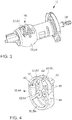
- Fig. 4 shows a perspective view of the cage 16 from Fig. 1 ,
- the cage 16 has two dosing lugs 42.
- the production of the geometry of the opening 18 and the metering lugs 42 which are formed at the edge 34 of the opening 18 by means of the valve member 12 is subject to demoulding limits.
- the demoulding limits can be shifted by special tools.
- the special tools may be disassembled or folded to be pulled out of the valve member 12 after molding. Due to the use of metering lugs 42 of the cage 16 flow-optimizing geometries of the valve assembly 10 can be made more free, since geometries that are difficult or impossible to produce with the valve member 12 manufacturing technology, are transferred to the cage 16.
- Fig. 5 shows a perspective view of the valve member 12 and the cage 16 from Fig. 1 in assembled form.
- the cage 16 has a dosing nose 42.
- the valve member 12 at the edge 34 of the opening 18 on two doses 42.
- the metering lugs 42 can be formed only by means of the cage 16, only by means of the valve member 12 at the edge 34 of the opening 18 or both by means of the cage 16 and by means of the valve member 12.
Landscapes
- Engineering & Computer Science (AREA)
- General Engineering & Computer Science (AREA)
- Mechanical Engineering (AREA)
- Lift Valve (AREA)
Abstract
Description
- Die Erfindung betrifft eine Ventilanordnung gemäß dem Oberbegriff des Patentanspruchs 1.
- Herkömmliche Brennkraftmaschinen weisen regelmäßig einen oder mehrere Kühlmittelkreisläufe zur Kühlung auf, wobei das Kühlmittel bspw. durch einen ersten Kühlmittelweg mit einem Wärmetauscher oder durch einen zweiten Kühlmittelweg ohne Wärmetauscher geleitet werden kann. Zur Regelung der durch die verschiedenen Kühlmittelwege zu leitenden Kühlmittelmengen sind regelmäßig Ventilanordnungen, wie etwa Drehschieberventile, vorgesehen. Ventilanordnungen weisen ein verstellbares Ventilglied, wie etwa einen Drehschieber, auf, das in einer ersten Ventilstellung einen Durchgang zwischen einem Fluidzuführkanal und einem ersten Fluidableitkanal freigibt und in einer zweiten Ventilstellung einen Durchgang zwischen dem Fluidzuführkanal und einem zweiten Fluidableitkanal freigibt. Auch Zwischenstellungen des Ventilglieds sind möglich, bspw. um eine optimale Kühlmitteltemperatur einstellen zu können.
- In den jeweiligen Ventilstellungen muss dafür gesorgt werden, dass das dem Ventilglied zugewandte Ende eines entsprechenden Fluidkanals dichtend an dem Ventilglied anliegt, so dass ein Vordringen des Kühlmittels zu nicht dafür vorgesehenen Bereichen der Ventilanordnung, wie etwa Bereichen mit elektrischen Bauteilen, verhindert wird. Damit kann eine Beschädigung der elektrischen Bauteile verhindert werden. Ferner soll in einer geschlossenen Ventilstellung kein Kühlmittel von dem Fluidkanal an dem Ventilglied vorbei weiter in die Ventilanordnung vordringen können und umgekehrt. Zu diesem Zweck ist regelmäßig ein zwischen dem beweglichen Ventilglied und dem Ende des Fluidkanals wirkendes Dichtelement vorgesehen.
- Das Dichtelement weist idealerweise ein Material auf, welches Unebenheiten des Ventilglieds möglichst gut ausgleichen kann, so dass das Dichtelement beim Gleiten des Dichtelements über das drehbare Ventilglied optimal gegen das Ventilglied abdichtet. Dies wird mittels eines weichen und/oder elastischen Materials erreicht.
- Ein weiches und/oder elastisches Material kann aber beim Drehen des Ventilglieds in die Öffnung des Ventilglieds eintauchen. Dadurch kann das Dichtelement beim Anstoßen gegen den Rand der Öffnung des Ventilglieds beschädigt werden. Mittels eines Auflaufstegs kann das Dichtelement wieder auf die Höhe des Rands der Öffnung gehoben werden.
- Der Auflaufsteg kann allerdings nicht beliebig verlängert werden. Das Ventilglied wird insbesondere im Spritzgussverfahren hergestellt. Dabei wird bei der Herstellung des Ventilglieds ein formgebendes Werkzeug verwendet. Dieses Werkzeug wird nach der Formgebung wieder aus dem Ventilglied gezogen. Kommt es zu einem sogenannten Hinterschnitt, dann ist es nötig, das Werkzeug in mehreren Teilen aus dem Ventilglied zu ziehen, oder es ist nötig, das Werkzeug zusammenzufalten und in diesem Zustand aus dem Ventilglied zu ziehen. Daher ergibt sich für die Geometrie der Öffnung eines Ventilglieds und des Auflaufstegs eine sogenannte entformungstechnische Grenze. Die Geometrie der Öffnung des Ventilglieds und des Auflaufstegs wird demnach so gewählt, dass das Werkzeug wieder aus dem Ventilglied gezogen werden kann. Dies betrifft auch die Geometrie der Dosiernasen, welche am Rand der Öffnungen des Ventilglieds zur feineren Regelung des Fluidstroms ausgebildet sein können.
- Die
US 5,287,889 A offenbart ein Ventilglied, bei welchem Dosiernasen ausgebildet sind. - Der Erfindung liegt die Aufgabe zugrunde, eine verbesserte Ventilanordnung bereitzustellen, bei der ein Eintauchen des Dichtelements in die Öffnung des Ventilglieds verhindert ist.
- Diese Aufgabe wird erfindungsgemäß durch eine Ventilanordnung mit den in Anspruch 1 gekennzeichneten Merkmalen gelöst. Vorteilhafte Ausgestaltungen der Erfindung sind in den weiteren Ansprüchen beschrieben.
- Dementsprechend wird eine Ventilanordnung, insbesondere ein Regelventil zur Regelung eines Kühlmittelkreislaufs einer Brennkraftmaschine, bereitgestellt. Die Ventilanordnung weist ein Ventilglied zum Leiten eines Fluids mit einer Öffnung und ein Dichtelement zum Abdichten eines Übergangs zwischen dem Ventilglied und einem Fluidkanal auf. Weiter umfasst die Ventilanordnung einen Käfig zum Unterbinden des Durchsackens des Dichtelements in die Öffnung des Ventilglieds. Dabei ist der Käfig in dem Ventilglied angeordnet. Zudem weist der Käfig einen freiliegenden Bereich an der Öffnung auf. An dem freiliegenden Bereich ist eine Kontur des Ventilglieds fortgeführt.
- Dadurch, dass die Ventilanordnung einen Käfig aufweist, kann ein Durchsacken des Dichtelements in die Öffnung des Ventilglieds vermieden werden. Beim Gleiten des Dichtelements über die Öffnung des Ventilglieds wird das Dichtelement durch den Käfig gestützt. Damit wird das Eintauchen des Dichtelements in die Öffnung verhindert.
- Dies hat den Vorteil, dass das Dichtelement nicht gegen einen Rand der Öffnung stößt und dadurch nicht beschädigt wird. Weiter kann die Öffnung des Ventilglieds größer ausgebildet sein und der Auflaufsteg kann verkürzt sein oder ganz entfallen. Dadurch wird das Entfernen des formgebenden Werkzeugs aus dem Ventilglied nach der Formgebung erleichtert.
- Das Fluid kann ein Kühlmittel und insbesondere eine Kühlflüssigkeit sein. Die Öffnung ist eine Durchströmöffnung für das Fluid in der Mantelfläche des Ventilglieds. Weiter kann das Dichtelement als einstückiges oder mehrteiliges Bauteil ausgeführt sein.
- Der Käfig ist ein für das Fluid durchlässiges Bauteil, damit das Fluid von dem Ventilglied zu dem Fluidkanal, oder umgekehrt, strömen kann. Insbesondere verschließt der Käfig nicht die Öffnung des Ventilglieds.
- Der freiliegende Bereich des Käfigs ist derjenige Bereich des Käfigs, welcher nicht von dem Ventilglied umgeben ist, da er an der Öffnung des Ventilglieds liegt.
- An dem freiliegenden Bereich ist eine Kontur des Ventilglieds fortgeführt, indem der Käfig die Kontur des Ventilglieds weiterführt. Dabei ist unter dem Begriff Kontur der Umriss oder die Silhouette des Ventilglieds zu verstehen. Dementsprechend kann das Dichtelement gut über den freiliegenden Bereich gleiten. Insbesondere kann das Dichtelement auch gut über die Nahtstelle zwischen dem Ventilglied, d.h. dem Rand der Öffnung, und dem freiliegenden Bereich des Käfigs gleiten. Dies ist deshalb möglich, weil der Rand der Öffnung und der freiliegende Bereich des Ventilglieds einen möglichst nahtlosen Übergang bilden.
- Vorzugsweise umfasst der Käfig eine Gitterstruktur. Dabei weist der Käfig an dem an der Öffnung freiliegenden Bereich zumindest eine Kufe auf. Die Kufe erstreckt sich entlang einer Gleitrichtung des Dichtelements. Aufgrund der Gitterstruktur ist der Käfig gegenüber dem Fluid durchlässig. Dabei verhindert ein Gleiten des Dichtelements entlang der Kufe das Durchsacken des Dichtelements in die Öffnung.
- Die Gitterstruktur kann mittels Stäben und/oder Rohren gebildet werden. Dabei ist die Gitterstruktur im Wesentlichen hohl und die Stäbe und/oder Rohre machen nur einen kleinen Teil des Volumens aus. Insbesondere beträgt der durch die Stäbe und/oder Rohre gebildete Teil des Volumens weniger als 20%, weniger als 10%, weniger als 5% oder weniger als 3% des Volumens der Gitterstruktur.
- Die zumindest eine Kufe ist ein gebogenes Gleitelement, insbesondere ein gebogenes Rohr oder ein gebogener Stab. Die nach außen in Richtung des Dichtelements weisende Begrenzung der Kufe kann eine flache gebogene Fläche sein. Dabei führt die zumindest eine Kufe die Kontur des Ventilglieds fort. Weiter ist die zumindest eine Kufe so ausgerichtet, dass das Dichtelement beim Drehen des Ventilglieds entlang der Längsrichtung der Kufe gleitet.
- Der Käfig kann an dem an der Öffnung freiliegenden Bereich auch mehrere Kufen aufweisen. Insbesondere kann der Käfig zwei, drei oder vier Kufen aufweisen.
- In Weiterbildung der Erfindung ist es auch möglich, dass der Käfig zumindest ein durchlässiges Scheibenelement aufweist. Dabei kann das zumindest eine durchlässige Scheibenelement als ein Gitterelement ausgebildet sein, bei welchem alle Rohre und/oder Stäbe in einer Ebene verlaufen. Insbesondere kann der Käfig zwei, drei oder vier durchlässige Scheibenelemente aufweisen, welche geeignet miteinander verbunden sind.
- Alternativ ist es auch möglich, dass der Käfig als Schalensegment ausgebildet ist. In diesem Fall kann das Schalensegment unterhalb des Rands der Öffnung des Ventilglieds befestigt sein. Dabei ist der Übergang zwischen dem Ventilglied und dem Schalensegment möglichst glatt, um die Gleitbewegung des Dichtelements nicht negativ zu beeinflussen, damit sich das Dichtelement nicht unnötig abnützt.
- Das Schalensegment füllt nur einen kleinen Teil der Fläche der Öffnung aus. Insbesondere beträgt der durch das Schalensegment gebildete Teil der Fläche weniger als 20%, weniger als 10%, weniger als 5% oder weniger als 3% der Fläche der Öffnung.
- Gemäß einer Ausführungsform der Ventilanordnung ist der Käfig durch die Öffnung in das Ventilglied einsteckbar. Vorteilhafterweise kann der Käfig dann einfach mit dem Ventilglied verbunden werden. Weiter kann die Einsteckrichtung des Käfigs der Richtung entsprechen, in der das formgebende Werkzeug nach der Formung aus dem Ventilglied gezogen wird.
- Vorzugsweise weist das Ventilglied eine konstante Wanddicke auf. Dadurch, dass die Wanddicke konstant gehalten wird, ist es möglich, eine sehr glatte Oberfläche des Ventilglieds zu realisieren. Mittels der sehr glatten Oberfläche gelingt wiederum eine sehr gute Abdichtung zwischen Ventilglied und Dichtelement.
- Zweckmäßigerweise kann zumindest eine Dosiernase an einem Rand der Öffnung ausgebildet sein. Dabei ist die zumindest eine Dosiernase ein Teil des Ventilglieds. Die zumindest eine Dosiernase dient dazu, die Strömung des Fluids durch die Öffnung beim Drehen des Ventilglieds besser, d.h. insbesondere feiner, regeln zu können.
- In Weiterbildung der Erfindung ist es auch möglich, dass zumindest eine Dosiernase mittels des Käfigs ausgebildet ist. Aus Herstellungsgründen ist es nicht möglich, die mittels des Rands der Öffnung ausgebildete Dosiernase beliebig weit in die Öffnung hineinragen zu lassen bzw. es ist nicht möglich, die Öffnung beliebig klein zu machen. Es ist zu beachten, dass die Öffnung des Ventilglieds so ausgebildet ist, dass ein formgebendes Werkzeug nach der Formgebung noch aus dem Ventilglied gezogen werden kann.
- Dementsprechend wird eine Geometrie des Ventilglieds, die fertigungstechnisch nur schwer oder sogar gar nicht darstellbar ist, auf den Käfig übertragen. Der Käfig kann demzufolge auch zumindest eine Dosiernase aufweisen. Dabei kann die zumindest eine Dosiernase einstückig mit dem restlichen Käfig ausgebildet sein. Alternativ kann die zumindest eine Dosiernase auch als separates Element ausgebildet sein, welches mit dem restlichen Käfig verbunden ist.
- Zweckmäßigerweise kann das Ventilglied Kunststoff aufweisen oder aus Kunststoff bestehen. Vorteilhafterweise kann das Ventilglied dann in einem Spritzgussverfahren hergestellt sein.
- Es liegt schließlich im Rahmen der Erfindung, dass das Dichtelement Polytetrafluorethylen (PTFE) und/oder ein gleitoptimiertes Elastomer aufweist oder aus einem oder beiden dieser Materialien besteht. Insbesondere der Bereich des Dichtelements, welcher mit dem Ventilglied in Berührung kommt, ist zum Gleiten auf dem Ventilglied, bei einer Drehung des Ventilglieds, geeignet.
- Weitere mögliche Implementierungen der Erfindung umfassen auch nicht explizit genannte Kombinationen von zuvor oder im Folgenden beschriebenen Merkmalen.
- Dabei wird der Fachmann auch Einzelaspekte als Verbesserungen oder Ergänzungen zu der jeweiligen Grundform der Erfindung hinzufügen.
- Die Erfindung wird im Folgenden anhand der Zeichnungen näher erläutert. Diese zeigen in
- Fig. 1
- eine Explosionsansicht einer erfindungsgemäßen Ventilanordnung,
- Fig. 2
- eine perspektivische Ansicht des Ventilglieds und des Käfigs aus
Fig. 1 in teilweise zusammengebauter Form, - Fig. 3
- eine perspektivische Ansicht des Ventilglieds und des Käfigs aus
Fig. 1 in zusammengebauter Form, - Fig. 4
- eine perspektivische Ansicht des Käfigs aus
Fig. 1 mit Dosiernasen, und - Fig. 5
- eine perspektivische Ansicht des Ventilglieds und des Käfigs aus
Fig. 1 in zusammengebauter Form, wobei der Käfig eine Dosiernase aufweist. - In den Figuren sind gleiche oder funktionsgleiche Elemente mit denselben Bezugszeichen versehen worden. Ferner sollte beachtet werden, dass die Darstellungen in den Figuren nicht notwendigerweise maßstabsgerecht sind.
-
Fig. 1 zeigt eine Explosionsansicht einer erfindungsgemäßen Ventilanordnung 10. Bei der Ventilanordnung 10 kann es sich insbesondere um ein Regelventil zur Regelung eines Kühlmittelkreislaufs einer Brennkraftmaschine handeln. Die Ventilanordnung 10 weist ein Ventilglied 12, ein Dichtelement 14 und einen Käfig 16 auf. Das Ventilglied 12 dient zum Leiten eines Fluids. Das Fluid kann an einer Öffnung 18 in der Mantelfläche 20 des Ventilglieds 12 aus- oder eintreten. Dagegen dient das Dichtelement 14 zum Abdichten eines Übergangs zwischen dem Ventilglied 12 und einem Fluidkanal (inFig. 1 nicht dargestellt). Der Fluidkanal wird durch ein an das Dichtelement angrenzendes Gehäuse gebildet. Der Übergang stellt den Bereich zwischen dem Ventilglied 12 und dem Fluidkanal dar. - Der Käfig 16 unterbindet ein Durchsacken des Dichtelements 14 in die Öffnung 18 des Ventilglieds 12. Dabei ist der Käfig 16 in dem Ventilglied 12 angeordnet. Weiter weist der Käfig 16 einen freiliegenden Bereich 22 auf. An dem freiliegenden Bereich 22 ist die Kontur 24 des Ventilglieds 12 fortgeführt.
- Bei dem in der
Fig. 1 dargestellten Ventilglied 12 ist die Kontur 24 im Bereich der Öffnung 18 kugelförmig. Alternativ könnte die Kontur 24 im Bereich der Öffnung 18 aber auch beispielsweise zylinderförmig sein. Die Geometrie des Dichtelements 14 wird entsprechend der Kontur 24 des Ventilglieds 12 im Bereich der Öffnung 18 ausgebildet. - Das in
Fig. 1 gezeigte Dichtelement 14 weist eine metallische Führungshülse 26, ein Vorspannelement 28, einen Elastomer-Dichtring (inFig. 1 nicht gezeigt) und eine Dichthülse 30 aus Kunststoff auf. Die Führungshülse 26 und die Dichthülse 30 überlappen einander zumindest abschnittsweise und sind relativ zueinander in Richtung der Achse 32, d.h. in axialer Richtung, beweglich. Dabei drückt das Vorspannelement 28 die Führungshülse 26 und die Dichthülse 30 auseinander. - Mittels des Vorspannelements 28 wird die Dichthülse 30 gegen das Ventilglied 12 gedrückt, um gegen das Ventilglied 12 abzudichten. Weiter wird mittels des Vorspannelements 28 die Führungshülse 26 gegen den Fluidkanal (in
Fig. 1 nicht dargestellt) gedrückt, um gegen den Fluidkanal abzudichten. Der Elastomer-Dichtring dichtet den Bereich zwischen der Führungshülse 26 und der Dichthülse 30 ab. Das Dichtelement 14 ist dementsprechend druckvorgespannt zwischen dem Fluidkanal, d.h. dem Gehäuse, welches den Fluidkanal bildet, und dem Ventilglied 12 positioniert. - Das Eintauchen des Dichtelements 14 in die Öffnung 18 beim Drehen des Ventilglieds 12 wird durch den Käfig 16 verhindert, da das Dichtelement 14 auf dem Käfig 16 gleiten kann. Dadurch wird eine Kollision zwischen dem Dichtelement 14 mit dem Rand 34 der Öffnung 18 verhindert. Dementsprechend ist eine Beschädigung des Dichtelements 14 weitgehend ausgeschlossen. Weiter kann die Öffnung 18 aufgrund fertigungstechnischer Gesichtspunkte gebildet werden, ohne Rücksicht auf den Aspekt des Absinkens des Dichtelements 14 in die Öffnung 18.
- Die Ventilanordnung 12 zeigt einen optionalen Auflaufsteg 36. Mittels des optionalen Auflaufstegs 36 wird das Dichtelement 14 beim Drehen des Ventilglieds 12 aus der Öffnung 18 wieder auf die Mantelfläche 20 gehoben. Der optionale Auflaufsteg 36 dient ebenfalls dazu, eine Kollision zwischen dem Dichtelement 14 und dem Rand 34 der Öffnung 18 zu verhindern. Der Käfig 16 kann nicht die gesamte Öffnung 18 verschließen, da ansonsten kein Fluid mehr durch die Öffnung 18 fließen könnte. Daher kann der optionale Auflaufsteg 36 sinnvoll in von dem Käfig 16 entfernten Bereichen am Rand 34 der Öffnung 18 eingesetzt werden. Aus fertigungstechnischen Gründen kann der Auflaufsteg 36 nicht beliebig weit in die Öffnung 18 hineinragen.
- Wie
Fig. 1 zeigt, ist der Käfig 16 durch die Öffnung 18 in das Ventilglied 12 einsteckbar. Das Einstecken kann über eine Steckverbindung realisiert werden. Dazu können das Ventilglied 12 und der Käfig 16 formschlüssig verbunden werden. Beispielsweise ist an der Innenseite des Ventilglieds 12 eine Schiene 38 vorgesehen, welche passend in eine Nut 40 des Käfigs 16 eingreifen kann. - Die Einsteckrichtung des Käfigs 16 entspricht der Entformungsrichtung, d.h. der Richtung, in der ein formgebendes Werkzeug nach der Formgebung aus dem Ventilglied 12 gezogen wird. Dies erlaubt eine einfache Montage und Fixierung des Käfigs 16 in dem Ventilglied 12.
- Das Ventilglied 12 kann vollständig oder teilweise aus Kunststoff bestehen. Insbesondere kann das Ventilglied 12 im Spritzgussverfahren hergestellt sein.
- Da der Käfig 16 ein Eintauchen des anliegenden Dichtelements 14 in die Öffnung 18 unterbindet, ist es nicht mehr erforderlich, das Dichtelement 14 steif auszuführen. Der Einsatz eines Dichtelements 14, welches im Kontaktbereich zum Ventilglied 12 weich ist, ermöglicht wiederum eine gute Kompensation von Oberflächenformfehlern (Mulden) an dem Ventilglied 12 und sorgt damit für eine gute Dichtwirkung. Dementsprechend kann das Dichtelement 14 ganz oder teilweise aus Polytetrafluorethylen (PTFE) und/oder einem gleitoptimierten Elastomer gebildet sein.
- Weiter kann die Öffnung 18 in Rotationsrichtung des Ventilglieds 12 speziell ausgebildet sein. Wie in
Fig. 1 dargestellt ist, sind an dem Rand 34 der Öffnung 18 zwei Dosiernasen 42 ausgebildet. Die Dosiernasen 42 dienen zum besseren, d.h. insbesondere feineren, Regeln des Volumenstroms des Fluids beim Drehen des Ventilglieds 12. - Der Käfig 16 ist vorzugsweise als Gitterstruktur 44 ausgebildet. Die in
Fig. 1 gezeigte Gitterstruktur 44 umfasst zwei Scheibenelemente 46, welche in einem Verbindungsbereich 48 miteinander verbunden sind. Die Scheibenelemente 46 sind gegenüber dem Fluid durchlässig. Weiter weist jedes Scheibenelement 46 drei Stäbe 50 sowie zwei gebogene Strukturen 52 auf. Genauer zeigtFig. 1 eine innere gebogene Struktur 54 und eine äußere gebogene Struktur 56. Dabei verbinden die Stäbe 50 die innere gebogene Struktur 54 und die äußere gebogene Struktur 56. Weiter dient die innere gebogene Struktur 54 zur Aufnahme einer Welle 58 (sieheFig. 3 ). Die äußere gebogene Struktur 56 stellt die äußere Begrenzung des Scheibenelements 46 dar. - Wie in
Fig. 1 dargestellt, ist in dem Verbindungsbereich 48 eine Nut 40 vorgesehen, um die Gitterstruktur 44 mit dem Ventilglied 12 formschlüssig zu verbinden. Der Käfig 16, d.h. die Gitterstruktur 44, weist einen Bereich auf, welcher nicht von dem Ventilglied 12 umschlossen ist, wenn sich der Käfig 16 in dem Ventilglied 12 befindet. An diesem sogenannten freiliegenden Bereich 22 weist der Käfig 16 zwei Kufen 60 auf. Die Kufen 60 sind Teilbereiche der äußeren gebogenen Strukturen 56. Dabei erstrecken sich die Kufen 60 entlang einer Gleitrichtung des Dichtelements 14. Dabei wird die Gleitrichtung des Dichtelements 14 durch die Rotation des Ventilglieds 12 mittels der Welle 58 bestimmt. - Die Anzahl der Stäbe 50 und/oder der gebogene Strukturen 52 eines Scheibenelements 46 kann zwischen 1 und 10, bevorzugt zwischen 1 und 5 und insbesondere zwischen 1 und 3 liegen. Weiter kann die Anzahl der Scheibenelemente 46 eines Käfigs 16 zwischen 1 und 5 und bevorzugt zwischen 1 und 3 liegen.
-
Fig. 2 zeigt eine perspektivische Ansicht des Ventilglieds 12 und des Käfigs 16 ausFig. 1 in teilweise zusammengebauter Form. Dabei ist der Käfig 16 bereits ein Stück weit mittels der Nut 40 entlang der Schiene 38 in das Ventilglied 12 geschoben. -
Fig. 3 zeigt eine perspektivische Ansicht des Ventilglieds 12 und des Käfigs 16 ausFig. 1 in zusammengebauter Form. Der Käfig 16 ist vollständig in das Ventilglied 12 eingesteckt und mittels der Welle 58 zusätzlich fixiert. Dabei ist der Käfig 16 so in dem Ventilglied 12 angeordnet und ausgebildet, dass mittels der Kufen 60 die Kontur 24 der Mantelfläche 20 des Ventilglieds 12 im freiliegenden Bereich 22 fortgeführt ist. - Das Ventilglied 12 weist eine konstante Wanddicke auf. Dadurch kann eine glatte Oberfläche an der Mantelfläche 20 des Ventilglieds 12 realisiert werden.
- Alternativ kann der Käfig 16 auch als Schalensegment ausgebildet sein. In diesem Fall erstreckt sich das Schalensegment von einem Rand 34 zu dem gegenüberliegenden Rand 34 der Öffnung 18. Dabei wird das Schalensegment unterhalb des Rands 34 der Öffnung 18 fixiert. Das Schalensegment kann ebenfalls eine oder mehrere Kufen 60 aufweisen, welche sich entlang der Gleitrichtung des Dichtelements 14 erstrecken. In jedem Fall führt das Schalensegment die Kontur 24 des Ventilglieds 12 im freiliegenden Bereich 22 fort.
-
Fig. 4 zeigt eine perspektivische Ansicht des Käfigs 16 ausFig. 1 . Zusätzlich weist der Käfig 16 zwei Dosiernasen 42 auf. - Die Herstellung der Geometrie der Öffnung 18 und der Dosiernasen 42, welche am Rand 34 der Öffnung 18 mittels des Ventilglieds 12 ausgebildet sind, unterliegt entformungstechnischen Grenzen. Dabei können die entformungstechnischen Grenzen durch Spezialwerkzeuge verschoben werden. Insbesondere können die Spezialwerkzeuge auseinandergebaut oder gefaltet werden, um nach der Formgebung aus dem Ventilglied 12 gezogen zu werden. Aufgrund des Einsatzes von Dosiernasen 42 des Käfigs 16 können strömungsoptimierende Geometrien der Ventilanordnung 10 freier gestaltet werden, da Geometrien, die mit dem Ventilglied 12 fertigungstechnisch schwer oder gar nicht darstellbar sind, auf den Käfig 16 übertragen werden.
-
Fig. 5 zeigt eine perspektivische Ansicht des Ventilglieds 12 und des Käfigs 16 ausFig. 1 in zusammengebauter Form. Dabei weist der Käfig 16 eine Dosiernase 42 auf. Ebenso weist das Ventilglied 12 am Rand 34 der Öffnung 18 zwei Dosiernasen 42 auf. - Prinzipiell können die Dosiernasen 42 nur mittels des Käfigs 16, nur mittels des Ventilglieds 12 am Rand 34 der Öffnung 18 oder sowohl mittels des Käfigs 16 als auch mittels des Ventilglieds 12 ausgebildet sein.
-
- 10
- Ventilanordnung
- 12
- Ventilglied
- 14
- Dichtelement
- 16
- Käfig
- 18
- Öffnung
- 20
- Mantelfläche
- 22
- freiliegender Bereich des Käfigs
- 24
- Kontur des Ventilglieds
- 26
- Führungshülse
- 28
- Vorspannelement
- 30
- Dichthülse
- 32
- Achse
- 34
- Rand der Öffnung
- 36
- Auflaufsteg
- 38
- Schiene
- 40
- Nut
- 42
- Dosiernase
- 44
- Gitterstruktur
- 46
- Scheibenelement
- 48
- Verbindungsbereich
- 50
- Stab
- 52
- gebogene Struktur
- 54
- innere gebogene Struktur
- 56
- äußere gebogene Struktur
- 58
- Welle
- 60
- Kufe
Claims (10)
- Ventilanordnung (10), insbesondere Regelventil zur Regelung eines Kühlmittelkreislaufs einer Brennkraftmaschine, aufweisend
ein Ventilglied (12) zum Leiten eines Fluids mit einer Öffnung (18), und
ein Dichtelement (14) zum Abdichten eines Übergangs zwischen dem Ventilglied (12) und einem Fluidkanal,
dadurch gekennzeichnet, dass die Ventilanordnung (10) einen Käfig (16) zum Unterbinden des Durchsackens des Dichtelements (14) in die Öffnung (18) des Ventilglieds (12) aufweist, wobei der Käfig (16) in dem Ventilglied (12) angeordnet ist und einen freiliegenden Bereich (22) an der Öffnung (18) aufweist, an welchem eine Kontur (24) des Ventilglieds (12) fortgeführt ist. - Ventilanordnung nach Anspruch 1, dadurch gekennzeichnet, dass der Käfig (16) eine Gitterstruktur (44) umfasst, wobei der Käfig (16) an dem an der Öffnung (18) freiliegenden Bereich (22) zumindest eine Kufe (60) aufweist, welche sich entlang einer Gleitrichtung des Dichtelements (14) erstreckt.
- Ventilanordnung nach Anspruch 1 oder 2, dadurch gekennzeichnet, dass der Käfig (16) zumindest ein durchlässiges Scheibenelement (46) aufweist.
- Ventilanordnung nach Anspruch 1 oder 2, dadurch gekennzeichnet, dass der Käfig (16) als Schalensegment ausgebildet ist.
- Ventilanordnung nach mindestens einem der vorhergehenden Ansprüche, dadurch gekennzeichnet, dass der Käfig (16) durch die Öffnung (18) in das Ventilglied (12) einsteckbar ist.
- Ventilanordnung nach mindestens einem der vorhergehenden Ansprüche, dadurch gekennzeichnet, dass das Ventilglied (12) eine konstante Wanddicke aufweist.
- Ventilanordnung nach mindestens einem der vorhergehenden Ansprüche, dadurch gekennzeichnet, dass zumindest eine Dosiernase (42) an einem Rand (34) der Öffnung (18) ausgebildet ist.
- Ventilanordnung nach mindestens einem der vorhergehenden Ansprüche, dadurch gekennzeichnet, dass zumindest eine Dosiernase (42) mittels des Käfigs (16) ausgebildet ist.
- Ventilanordnung nach mindestens einem der vorhergehenden Ansprüche, dadurch gekennzeichnet, dass das Ventilglied (12) Kunststoff aufweist oder aus Kunststoff besteht.
- Ventilanordnung nach mindestens einem der vorhergehenden Ansprüche, dadurch gekennzeichnet, dass das Dichtelement (14) Polytetrafluorethylen (PTFE) und/oder ein gleitoptimiertes Elastomer aufweist oder aus einem oder beiden dieser Materialien besteht.
Applications Claiming Priority (1)
| Application Number | Priority Date | Filing Date | Title |
|---|---|---|---|
| DE102016225372.7A DE102016225372A1 (de) | 2016-12-19 | 2016-12-19 | Ventilanordnung mit Käfig |
Publications (2)
| Publication Number | Publication Date |
|---|---|
| EP3339699A1 true EP3339699A1 (de) | 2018-06-27 |
| EP3339699B1 EP3339699B1 (de) | 2020-02-19 |
Family
ID=60661804
Family Applications (1)
| Application Number | Title | Priority Date | Filing Date |
|---|---|---|---|
| EP17206310.9A Active EP3339699B1 (de) | 2016-12-19 | 2017-12-11 | Ventilanordnung mit käfig |
Country Status (3)
| Country | Link |
|---|---|
| EP (1) | EP3339699B1 (de) |
| CN (1) | CN108204464B (de) |
| DE (1) | DE102016225372A1 (de) |
Cited By (1)
| Publication number | Priority date | Publication date | Assignee | Title |
|---|---|---|---|---|
| US20240209960A1 (en) * | 2022-11-29 | 2024-06-27 | Fisher Controls International Llc | Noise Attenuation Assembly for Flow Control Devices |
Citations (4)
| Publication number | Priority date | Publication date | Assignee | Title |
|---|---|---|---|---|
| US20070034267A1 (en) * | 2005-08-09 | 2007-02-15 | Spx Corporation | Valve assembly and method with slotted plates and spherical ball plug |
| US20100163774A1 (en) * | 2008-12-31 | 2010-07-01 | Vladimir Rimboym | Fluid Control Valve |
| DE102014218386A1 (de) * | 2014-09-12 | 2016-03-17 | Mahle International Gmbh | Ventil für eine Regelung von Volumenströmen |
| US20170321815A1 (en) * | 2016-05-04 | 2017-11-09 | Johnson Electric S.A. | Ball Valve Apparatus |
Family Cites Families (7)
| Publication number | Priority date | Publication date | Assignee | Title |
|---|---|---|---|---|
| US5287889A (en) | 1992-09-22 | 1994-02-22 | Leinen Christopher M | Low-noise rotary control valve |
| US5680889A (en) * | 1996-09-23 | 1997-10-28 | Dresser Industries, Inc. | Low noise ball valve assembly |
| ITMI20030889A1 (it) * | 2003-04-30 | 2004-11-01 | Pibiviesse S P A | Valvola di regolazione |
| ITMI20032454A1 (it) * | 2003-12-15 | 2005-06-16 | Pibiviesse S P A | Valvola a sfera con elevato smorzamento del rumore di passaggio del fluido |
| CN201764001U (zh) * | 2010-09-16 | 2011-03-16 | 苏州德兰能源科技有限公司 | 一种迷宫式金属密封调节球阀 |
| CN202432002U (zh) * | 2011-11-14 | 2012-09-12 | 大连亨利测控仪表工程有限公司 | 高压差v型调节球阀 |
| CN104913076A (zh) * | 2015-06-03 | 2015-09-16 | 航天长征化学工程股份有限公司 | 一种低噪声的切断球阀 |
-
2016
- 2016-12-19 DE DE102016225372.7A patent/DE102016225372A1/de not_active Withdrawn
-
2017
- 2017-12-11 EP EP17206310.9A patent/EP3339699B1/de active Active
- 2017-12-19 CN CN201711374016.9A patent/CN108204464B/zh active Active
Patent Citations (4)
| Publication number | Priority date | Publication date | Assignee | Title |
|---|---|---|---|---|
| US20070034267A1 (en) * | 2005-08-09 | 2007-02-15 | Spx Corporation | Valve assembly and method with slotted plates and spherical ball plug |
| US20100163774A1 (en) * | 2008-12-31 | 2010-07-01 | Vladimir Rimboym | Fluid Control Valve |
| DE102014218386A1 (de) * | 2014-09-12 | 2016-03-17 | Mahle International Gmbh | Ventil für eine Regelung von Volumenströmen |
| US20170321815A1 (en) * | 2016-05-04 | 2017-11-09 | Johnson Electric S.A. | Ball Valve Apparatus |
Cited By (2)
| Publication number | Priority date | Publication date | Assignee | Title |
|---|---|---|---|---|
| US20240209960A1 (en) * | 2022-11-29 | 2024-06-27 | Fisher Controls International Llc | Noise Attenuation Assembly for Flow Control Devices |
| US12331847B2 (en) * | 2022-11-29 | 2025-06-17 | Fisher Controls International Llc | Noise attenuation assembly for flow control devices |
Also Published As
| Publication number | Publication date |
|---|---|
| CN108204464A (zh) | 2018-06-26 |
| CN108204464B (zh) | 2020-11-10 |
| DE102016225372A1 (de) | 2018-07-05 |
| EP3339699B1 (de) | 2020-02-19 |
Similar Documents
| Publication | Publication Date | Title |
|---|---|---|
| WO1998036817A1 (de) | Scheibe, insbesondere stirnscheibe eines filtereinsatzes | |
| DE4408888A1 (de) | Filter für eine Brennkraftmaschine | |
| DE2804676C2 (de) | Drosselklappenventil mit einer einstückigen Dichtungsmanschette | |
| WO2016016185A1 (de) | Ventil für einen fluidkreislauf eines kraftfahrzeugs | |
| EP1621316B1 (de) | Spritzgiessform zum Herstellen von Fittings | |
| DE102007006872B4 (de) | Kugelsitzventil mit konturiertem Steuerstößel | |
| DE102019103210A1 (de) | Winkelstück zum fluidkommunizierenden Verbinden von Fluidleitungen eines Fahrzeugs | |
| EP3339699B1 (de) | Ventilanordnung mit käfig | |
| DE102016220876A1 (de) | Ventilanordnung | |
| DE3142047A1 (de) | Vorrichtung zum druckgiessen eines waelzlagerkaefigs | |
| EP1106817A2 (de) | Ventil mit verbesserter Anschlaggeometrie | |
| WO2023169669A1 (de) | Drehschieberventil eines kraftfahrzeug-kühlkreislaufs | |
| EP1534491B1 (de) | Verfahren zum abschliessen eines drosselklappenstutzens | |
| EP4344848B1 (de) | Spritzgegossener hohlkörper, vorrichtung zum herstellen eines solchen und verstellbarer fluidverteiler mit einem solchen | |
| WO2012048999A2 (de) | Vorrichtung zum einspritzen von kraftstoff | |
| DE102023124558A1 (de) | Spritzgegossener Hohlkörper, Vorrichtung zum Herstellen eines solchen und verstellbarer Fluidverteiler mit einem solchen | |
| DE202023105489U1 (de) | Ventilkäfig für ein Stellventil mit elastischem Bereich | |
| WO2015039745A2 (de) | Rotor für einen nockenwellenversteller, teileset zur herstellung eines rotors für einen nockenwellenversteller sowie verfahren zur herstellung eines gefügten bauteils, bevorzugt eines rotors für einen nockenwellenversteller | |
| EP3014104B1 (de) | Düsenbaugruppe für einen kraftstoffinjektor sowie kraftstoffinjektor | |
| DE10101054A1 (de) | Halteteilaufbau | |
| EP0901837B1 (de) | Brausekopf mit Reinigungsstiften | |
| DE4324547A1 (de) | Sanitäre Mischbatterie mit Thermostatsteuerung | |
| DE102010052745B4 (de) | Thermostatventilunterteil | |
| DE102004059974A1 (de) | Düsenbaugruppe und Einspritzventil | |
| DE102023001741A1 (de) | Wälzkörperkäfig und Verschiebeinheit |
Legal Events
| Date | Code | Title | Description |
|---|---|---|---|
| PUAI | Public reference made under article 153(3) epc to a published international application that has entered the european phase |
Free format text: ORIGINAL CODE: 0009012 |
|
| STAA | Information on the status of an ep patent application or granted ep patent |
Free format text: STATUS: THE APPLICATION HAS BEEN PUBLISHED |
|
| AK | Designated contracting states |
Kind code of ref document: A1 Designated state(s): AL AT BE BG CH CY CZ DE DK EE ES FI FR GB GR HR HU IE IS IT LI LT LU LV MC MK MT NL NO PL PT RO RS SE SI SK SM TR |
|
| AX | Request for extension of the european patent |
Extension state: BA ME |
|
| STAA | Information on the status of an ep patent application or granted ep patent |
Free format text: STATUS: REQUEST FOR EXAMINATION WAS MADE |
|
| 17P | Request for examination filed |
Effective date: 20190102 |
|
| RBV | Designated contracting states (corrected) |
Designated state(s): AL AT BE BG CH CY CZ DE DK EE ES FI FR GB GR HR HU IE IS IT LI LT LU LV MC MK MT NL NO PL PT RO RS SE SI SK SM TR |
|
| RIC1 | Information provided on ipc code assigned before grant |
Ipc: F16K 5/06 20060101AFI20190730BHEP Ipc: F16K 5/12 20060101ALI20190730BHEP |
|
| GRAP | Despatch of communication of intention to grant a patent |
Free format text: ORIGINAL CODE: EPIDOSNIGR1 |
|
| STAA | Information on the status of an ep patent application or granted ep patent |
Free format text: STATUS: GRANT OF PATENT IS INTENDED |
|
| INTG | Intention to grant announced |
Effective date: 20190917 |
|
| GRAS | Grant fee paid |
Free format text: ORIGINAL CODE: EPIDOSNIGR3 |
|
| GRAA | (expected) grant |
Free format text: ORIGINAL CODE: 0009210 |
|
| STAA | Information on the status of an ep patent application or granted ep patent |
Free format text: STATUS: THE PATENT HAS BEEN GRANTED |
|
| AK | Designated contracting states |
Kind code of ref document: B1 Designated state(s): AL AT BE BG CH CY CZ DE DK EE ES FI FR GB GR HR HU IE IS IT LI LT LU LV MC MK MT NL NO PL PT RO RS SE SI SK SM TR |
|
| REG | Reference to a national code |
Ref country code: CH Ref legal event code: EP |
|
| REG | Reference to a national code |
Ref country code: DE Ref legal event code: R096 Ref document number: 502017003860 Country of ref document: DE |
|
| REG | Reference to a national code |
Ref country code: AT Ref legal event code: REF Ref document number: 1235349 Country of ref document: AT Kind code of ref document: T Effective date: 20200315 |
|
| REG | Reference to a national code |
Ref country code: IE Ref legal event code: FG4D Free format text: LANGUAGE OF EP DOCUMENT: GERMAN |
|
| REG | Reference to a national code |
Ref country code: NL Ref legal event code: MP Effective date: 20200219 |
|
| PG25 | Lapsed in a contracting state [announced via postgrant information from national office to epo] |
Ref country code: NO Free format text: LAPSE BECAUSE OF FAILURE TO SUBMIT A TRANSLATION OF THE DESCRIPTION OR TO PAY THE FEE WITHIN THE PRESCRIBED TIME-LIMIT Effective date: 20200519 Ref country code: FI Free format text: LAPSE BECAUSE OF FAILURE TO SUBMIT A TRANSLATION OF THE DESCRIPTION OR TO PAY THE FEE WITHIN THE PRESCRIBED TIME-LIMIT Effective date: 20200219 Ref country code: RS Free format text: LAPSE BECAUSE OF FAILURE TO SUBMIT A TRANSLATION OF THE DESCRIPTION OR TO PAY THE FEE WITHIN THE PRESCRIBED TIME-LIMIT Effective date: 20200219 |
|
| REG | Reference to a national code |
Ref country code: LT Ref legal event code: MG4D |
|
| PG25 | Lapsed in a contracting state [announced via postgrant information from national office to epo] |
Ref country code: HR Free format text: LAPSE BECAUSE OF FAILURE TO SUBMIT A TRANSLATION OF THE DESCRIPTION OR TO PAY THE FEE WITHIN THE PRESCRIBED TIME-LIMIT Effective date: 20200219 Ref country code: IS Free format text: LAPSE BECAUSE OF FAILURE TO SUBMIT A TRANSLATION OF THE DESCRIPTION OR TO PAY THE FEE WITHIN THE PRESCRIBED TIME-LIMIT Effective date: 20200619 Ref country code: BG Free format text: LAPSE BECAUSE OF FAILURE TO SUBMIT A TRANSLATION OF THE DESCRIPTION OR TO PAY THE FEE WITHIN THE PRESCRIBED TIME-LIMIT Effective date: 20200519 Ref country code: GR Free format text: LAPSE BECAUSE OF FAILURE TO SUBMIT A TRANSLATION OF THE DESCRIPTION OR TO PAY THE FEE WITHIN THE PRESCRIBED TIME-LIMIT Effective date: 20200520 Ref country code: SE Free format text: LAPSE BECAUSE OF FAILURE TO SUBMIT A TRANSLATION OF THE DESCRIPTION OR TO PAY THE FEE WITHIN THE PRESCRIBED TIME-LIMIT Effective date: 20200219 Ref country code: LV Free format text: LAPSE BECAUSE OF FAILURE TO SUBMIT A TRANSLATION OF THE DESCRIPTION OR TO PAY THE FEE WITHIN THE PRESCRIBED TIME-LIMIT Effective date: 20200219 |
|
| PG25 | Lapsed in a contracting state [announced via postgrant information from national office to epo] |
Ref country code: NL Free format text: LAPSE BECAUSE OF FAILURE TO SUBMIT A TRANSLATION OF THE DESCRIPTION OR TO PAY THE FEE WITHIN THE PRESCRIBED TIME-LIMIT Effective date: 20200219 |
|
| PG25 | Lapsed in a contracting state [announced via postgrant information from national office to epo] |
Ref country code: RO Free format text: LAPSE BECAUSE OF FAILURE TO SUBMIT A TRANSLATION OF THE DESCRIPTION OR TO PAY THE FEE WITHIN THE PRESCRIBED TIME-LIMIT Effective date: 20200219 Ref country code: LT Free format text: LAPSE BECAUSE OF FAILURE TO SUBMIT A TRANSLATION OF THE DESCRIPTION OR TO PAY THE FEE WITHIN THE PRESCRIBED TIME-LIMIT Effective date: 20200219 Ref country code: CZ Free format text: LAPSE BECAUSE OF FAILURE TO SUBMIT A TRANSLATION OF THE DESCRIPTION OR TO PAY THE FEE WITHIN THE PRESCRIBED TIME-LIMIT Effective date: 20200219 Ref country code: ES Free format text: LAPSE BECAUSE OF FAILURE TO SUBMIT A TRANSLATION OF THE DESCRIPTION OR TO PAY THE FEE WITHIN THE PRESCRIBED TIME-LIMIT Effective date: 20200219 Ref country code: PT Free format text: LAPSE BECAUSE OF FAILURE TO SUBMIT A TRANSLATION OF THE DESCRIPTION OR TO PAY THE FEE WITHIN THE PRESCRIBED TIME-LIMIT Effective date: 20200712 Ref country code: DK Free format text: LAPSE BECAUSE OF FAILURE TO SUBMIT A TRANSLATION OF THE DESCRIPTION OR TO PAY THE FEE WITHIN THE PRESCRIBED TIME-LIMIT Effective date: 20200219 Ref country code: EE Free format text: LAPSE BECAUSE OF FAILURE TO SUBMIT A TRANSLATION OF THE DESCRIPTION OR TO PAY THE FEE WITHIN THE PRESCRIBED TIME-LIMIT Effective date: 20200219 Ref country code: SM Free format text: LAPSE BECAUSE OF FAILURE TO SUBMIT A TRANSLATION OF THE DESCRIPTION OR TO PAY THE FEE WITHIN THE PRESCRIBED TIME-LIMIT Effective date: 20200219 Ref country code: SK Free format text: LAPSE BECAUSE OF FAILURE TO SUBMIT A TRANSLATION OF THE DESCRIPTION OR TO PAY THE FEE WITHIN THE PRESCRIBED TIME-LIMIT Effective date: 20200219 |
|
| REG | Reference to a national code |
Ref country code: DE Ref legal event code: R097 Ref document number: 502017003860 Country of ref document: DE |
|
| PLBE | No opposition filed within time limit |
Free format text: ORIGINAL CODE: 0009261 |
|
| STAA | Information on the status of an ep patent application or granted ep patent |
Free format text: STATUS: NO OPPOSITION FILED WITHIN TIME LIMIT |
|
| 26N | No opposition filed |
Effective date: 20201120 |
|
| PG25 | Lapsed in a contracting state [announced via postgrant information from national office to epo] |
Ref country code: IT Free format text: LAPSE BECAUSE OF FAILURE TO SUBMIT A TRANSLATION OF THE DESCRIPTION OR TO PAY THE FEE WITHIN THE PRESCRIBED TIME-LIMIT Effective date: 20200219 |
|
| PG25 | Lapsed in a contracting state [announced via postgrant information from national office to epo] |
Ref country code: PL Free format text: LAPSE BECAUSE OF FAILURE TO SUBMIT A TRANSLATION OF THE DESCRIPTION OR TO PAY THE FEE WITHIN THE PRESCRIBED TIME-LIMIT Effective date: 20200219 Ref country code: SI Free format text: LAPSE BECAUSE OF FAILURE TO SUBMIT A TRANSLATION OF THE DESCRIPTION OR TO PAY THE FEE WITHIN THE PRESCRIBED TIME-LIMIT Effective date: 20200219 |
|
| REG | Reference to a national code |
Ref country code: CH Ref legal event code: PL |
|
| PG25 | Lapsed in a contracting state [announced via postgrant information from national office to epo] |
Ref country code: MC Free format text: LAPSE BECAUSE OF FAILURE TO SUBMIT A TRANSLATION OF THE DESCRIPTION OR TO PAY THE FEE WITHIN THE PRESCRIBED TIME-LIMIT Effective date: 20200219 |
|
| REG | Reference to a national code |
Ref country code: BE Ref legal event code: MM Effective date: 20201231 |
|
| PG25 | Lapsed in a contracting state [announced via postgrant information from national office to epo] |
Ref country code: LU Free format text: LAPSE BECAUSE OF NON-PAYMENT OF DUE FEES Effective date: 20201211 Ref country code: IE Free format text: LAPSE BECAUSE OF NON-PAYMENT OF DUE FEES Effective date: 20201211 |
|
| PG25 | Lapsed in a contracting state [announced via postgrant information from national office to epo] |
Ref country code: CH Free format text: LAPSE BECAUSE OF NON-PAYMENT OF DUE FEES Effective date: 20201231 Ref country code: LI Free format text: LAPSE BECAUSE OF NON-PAYMENT OF DUE FEES Effective date: 20201231 |
|
| PG25 | Lapsed in a contracting state [announced via postgrant information from national office to epo] |
Ref country code: TR Free format text: LAPSE BECAUSE OF FAILURE TO SUBMIT A TRANSLATION OF THE DESCRIPTION OR TO PAY THE FEE WITHIN THE PRESCRIBED TIME-LIMIT Effective date: 20200219 Ref country code: MT Free format text: LAPSE BECAUSE OF FAILURE TO SUBMIT A TRANSLATION OF THE DESCRIPTION OR TO PAY THE FEE WITHIN THE PRESCRIBED TIME-LIMIT Effective date: 20200219 Ref country code: CY Free format text: LAPSE BECAUSE OF FAILURE TO SUBMIT A TRANSLATION OF THE DESCRIPTION OR TO PAY THE FEE WITHIN THE PRESCRIBED TIME-LIMIT Effective date: 20200219 |
|
| PG25 | Lapsed in a contracting state [announced via postgrant information from national office to epo] |
Ref country code: MK Free format text: LAPSE BECAUSE OF FAILURE TO SUBMIT A TRANSLATION OF THE DESCRIPTION OR TO PAY THE FEE WITHIN THE PRESCRIBED TIME-LIMIT Effective date: 20200219 Ref country code: AL Free format text: LAPSE BECAUSE OF FAILURE TO SUBMIT A TRANSLATION OF THE DESCRIPTION OR TO PAY THE FEE WITHIN THE PRESCRIBED TIME-LIMIT Effective date: 20200219 |
|
| PG25 | Lapsed in a contracting state [announced via postgrant information from national office to epo] |
Ref country code: BE Free format text: LAPSE BECAUSE OF NON-PAYMENT OF DUE FEES Effective date: 20201231 |
|
| P01 | Opt-out of the competence of the unified patent court (upc) registered |
Effective date: 20230523 |
|
| REG | Reference to a national code |
Ref country code: AT Ref legal event code: MM01 Ref document number: 1235349 Country of ref document: AT Kind code of ref document: T Effective date: 20221211 |
|
| PG25 | Lapsed in a contracting state [announced via postgrant information from national office to epo] |
Ref country code: AT Free format text: LAPSE BECAUSE OF NON-PAYMENT OF DUE FEES Effective date: 20221211 |
|
| PG25 | Lapsed in a contracting state [announced via postgrant information from national office to epo] |
Ref country code: AT Free format text: LAPSE BECAUSE OF NON-PAYMENT OF DUE FEES Effective date: 20221211 |
|
| PGFP | Annual fee paid to national office [announced via postgrant information from national office to epo] |
Ref country code: GB Payment date: 20251223 Year of fee payment: 9 |
|
| PGFP | Annual fee paid to national office [announced via postgrant information from national office to epo] |
Ref country code: FR Payment date: 20251223 Year of fee payment: 9 |
|
| PGFP | Annual fee paid to national office [announced via postgrant information from national office to epo] |
Ref country code: DE Payment date: 20251231 Year of fee payment: 9 |
|
| PGFP | Annual fee paid to national office [announced via postgrant information from national office to epo] |
Ref country code: AT Payment date: 20260410 Year of fee payment: 5 |