EP3339104A1 - A current transport mechanism, in particular an electrical or electromechanical current bar - Google Patents
A current transport mechanism, in particular an electrical or electromechanical current bar Download PDFInfo
- Publication number
- EP3339104A1 EP3339104A1 EP17207212.6A EP17207212A EP3339104A1 EP 3339104 A1 EP3339104 A1 EP 3339104A1 EP 17207212 A EP17207212 A EP 17207212A EP 3339104 A1 EP3339104 A1 EP 3339104A1
- Authority
- EP
- European Patent Office
- Prior art keywords
- transport mechanism
- plug
- current transport
- conductor
- connection device
- Prior art date
- Legal status (The legal status is an assumption and is not a legal conclusion. Google has not performed a legal analysis and makes no representation as to the accuracy of the status listed.)
- Pending
Links
Images


Classifications
-
- B—PERFORMING OPERATIONS; TRANSPORTING
- B60—VEHICLES IN GENERAL
- B60L—PROPULSION OF ELECTRICALLY-PROPELLED VEHICLES; SUPPLYING ELECTRIC POWER FOR AUXILIARY EQUIPMENT OF ELECTRICALLY-PROPELLED VEHICLES; ELECTRODYNAMIC BRAKE SYSTEMS FOR VEHICLES IN GENERAL; MAGNETIC SUSPENSION OR LEVITATION FOR VEHICLES; MONITORING OPERATING VARIABLES OF ELECTRICALLY-PROPELLED VEHICLES; ELECTRIC SAFETY DEVICES FOR ELECTRICALLY-PROPELLED VEHICLES
- B60L5/00—Current collectors for power supply lines of electrically-propelled vehicles
- B60L5/38—Current collectors for power supply lines of electrically-propelled vehicles for collecting current from conductor rails
-
- H—ELECTRICITY
- H01—ELECTRIC ELEMENTS
- H01R—ELECTRICALLY-CONDUCTIVE CONNECTIONS; STRUCTURAL ASSOCIATIONS OF A PLURALITY OF MUTUALLY-INSULATED ELECTRICAL CONNECTING ELEMENTS; COUPLING DEVICES; CURRENT COLLECTORS
- H01R25/00—Coupling parts adapted for simultaneous co-operation with two or more identical counterparts, e.g. for distributing energy to two or more circuits
- H01R25/16—Rails or bus-bars provided with a plurality of discrete connecting locations for counterparts
-
- B—PERFORMING OPERATIONS; TRANSPORTING
- B60—VEHICLES IN GENERAL
- B60R—VEHICLES, VEHICLE FITTINGS, OR VEHICLE PARTS, NOT OTHERWISE PROVIDED FOR
- B60R16/00—Electric or fluid circuits specially adapted for vehicles and not otherwise provided for; Arrangement of elements of electric or fluid circuits specially adapted for vehicles and not otherwise provided for
- B60R16/02—Electric or fluid circuits specially adapted for vehicles and not otherwise provided for; Arrangement of elements of electric or fluid circuits specially adapted for vehicles and not otherwise provided for electric constitutive elements
- B60R16/0207—Wire harnesses
- B60R16/0215—Protecting, fastening and routing means therefor
-
- B—PERFORMING OPERATIONS; TRANSPORTING
- B60—VEHICLES IN GENERAL
- B60L—PROPULSION OF ELECTRICALLY-PROPELLED VEHICLES; SUPPLYING ELECTRIC POWER FOR AUXILIARY EQUIPMENT OF ELECTRICALLY-PROPELLED VEHICLES; ELECTRODYNAMIC BRAKE SYSTEMS FOR VEHICLES IN GENERAL; MAGNETIC SUSPENSION OR LEVITATION FOR VEHICLES; MONITORING OPERATING VARIABLES OF ELECTRICALLY-PROPELLED VEHICLES; ELECTRIC SAFETY DEVICES FOR ELECTRICALLY-PROPELLED VEHICLES
- B60L5/00—Current collectors for power supply lines of electrically-propelled vehicles
- B60L5/42—Current collectors for power supply lines of electrically-propelled vehicles for collecting current from individual contact pieces connected to the power supply line
-
- H—ELECTRICITY
- H01—ELECTRIC ELEMENTS
- H01R—ELECTRICALLY-CONDUCTIVE CONNECTIONS; STRUCTURAL ASSOCIATIONS OF A PLURALITY OF MUTUALLY-INSULATED ELECTRICAL CONNECTING ELEMENTS; COUPLING DEVICES; CURRENT COLLECTORS
- H01R3/00—Electrically-conductive connections not otherwise provided for
-
- H—ELECTRICITY
- H02—GENERATION; CONVERSION OR DISTRIBUTION OF ELECTRIC POWER
- H02B—BOARDS, SUBSTATIONS OR SWITCHING ARRANGEMENTS FOR THE SUPPLY OR DISTRIBUTION OF ELECTRIC POWER
- H02B1/00—Frameworks, boards, panels, desks, casings; Details of substations or switching arrangements
- H02B1/20—Bus-bar or other wiring layouts, e.g. in cubicles, in switchyards
-
- H—ELECTRICITY
- H01—ELECTRIC ELEMENTS
- H01R—ELECTRICALLY-CONDUCTIVE CONNECTIONS; STRUCTURAL ASSOCIATIONS OF A PLURALITY OF MUTUALLY-INSULATED ELECTRICAL CONNECTING ELEMENTS; COUPLING DEVICES; CURRENT COLLECTORS
- H01R2201/00—Connectors or connections adapted for particular applications
- H01R2201/26—Connectors or connections adapted for particular applications for vehicles
-
- H—ELECTRICITY
- H01—ELECTRIC ELEMENTS
- H01R—ELECTRICALLY-CONDUCTIVE CONNECTIONS; STRUCTURAL ASSOCIATIONS OF A PLURALITY OF MUTUALLY-INSULATED ELECTRICAL CONNECTING ELEMENTS; COUPLING DEVICES; CURRENT COLLECTORS
- H01R25/00—Coupling parts adapted for simultaneous co-operation with two or more identical counterparts, e.g. for distributing energy to two or more circuits
- H01R25/16—Rails or bus-bars provided with a plurality of discrete connecting locations for counterparts
- H01R25/161—Details
-
- H—ELECTRICITY
- H01—ELECTRIC ELEMENTS
- H01R—ELECTRICALLY-CONDUCTIVE CONNECTIONS; STRUCTURAL ASSOCIATIONS OF A PLURALITY OF MUTUALLY-INSULATED ELECTRICAL CONNECTING ELEMENTS; COUPLING DEVICES; CURRENT COLLECTORS
- H01R4/00—Electrically-conductive connections between two or more conductive members in direct contact, i.e. touching one another; Means for effecting or maintaining such contact; Electrically-conductive connections having two or more spaced connecting locations for conductors and using contact members penetrating insulation
- H01R4/04—Electrically-conductive connections between two or more conductive members in direct contact, i.e. touching one another; Means for effecting or maintaining such contact; Electrically-conductive connections having two or more spaced connecting locations for conductors and using contact members penetrating insulation using electrically conductive adhesives
Definitions
- the invention relates to a vehicle current transport mechanism, in particular for a motor vehicle. Furthermore, the invention relates to a current transport mechanism, in particular a current bar, a backbone or a bus bar for the automotive industry. Moreover, the invention relates to an entity, a mechanism, a module, a subassembly, an appliance, an apparatus, a machine, a conveying means, a transport means, a system or a unit.
- connection mechanisms serve to transmit electrical currents, voltages and/or signals at a wide range of currents, voltages and/or frequencies.
- connection mechanisms of this kind In the low-voltage, medium-voltage or high-voltage range and/or in the low-current, medium-current or high-current range, connection mechanisms of this kind have to ensure transmission of current, voltage and/or signals in warm, possibly hot, contaminated, humid and/or chemically aggressive environments permanently, repeatedly and/or after a comparatively long service life, possibly at short notice.
- connection mechanisms By virtue of a wide range of applications, a great number of specially configured connection mechanisms are known.
- Cable harnesses with flexible or three-dimensionally deflectable electrical conductors made of copper are used today for transporting currents, in particular centrally transporting currents in a vehicle, preferably a motor vehicle.
- copper has the disadvantage of a comparatively high weight and a comparatively high purchase price for a particular amount of copper.
- the price disadvantage and weight disadvantage for copper also applies if a copper part is intended to be electrically adequately substituted with a non-copper part.
- only undirected tensile forces can be mechanically transmitted onto flexible conductors, which makes their structure and assembly laborious as such a structure and/or assembly cannot usually be carried out in an automated manner.
- a problem of the invention is to specify a vehicle current transport mechanism, in particular for a motor vehicle, and a current transport mechanism, in particular a current bar, a backbone or a bus bar for the automotive industry.
- the current transport mechanism should be able to be manufactured and/or assembled easily, in particular in an automated manner, wherein the current transport mechanism is intended to possess lower manufacturing costs and/or assembly costs relative to an electrically adequate cable harness made of copper.
- more than just undirected tensile forces are intended to be able to be transmitted by means of the current transport mechanism in order to facilitate an assembly of the current transport mechanism or to be able to optionally carry out an assembly in an automated manner.
- the problem of the invention is solved by means of a vehicle current transport mechanism, in particular for a motor vehicle; by means of a current transport mechanism, in particular a current bar, a backbone or a bus bar for the automotive industry; and by means of an entity, a mechanism, a module, a subassembly, an appliance, an apparatus, a machine, a conveying means, a transport means, a system or a unit, according to the independent claims.
- the inventive vehicle current transport mechanism has an elongated, electromechanical base conductor, the base conductor comprising at least one electrically-rigidly mechanical plug-in connection device which is connected thereto in an electrically-rigidly mechanical manner, and which in turn can be electrically contacted by an electrically-rigidly mechanical mating plug-in connection device. - Consequently, an electrical or electromechanical terminal of a flexible electrical conductor or of a flexible electrical cable at the vehicle current transport mechanism is possible.
- the electromechanical base conductor is formed mechanically stiffly or rigidly at least in sections and in all of its sections or across its entire extension substantially in at least two spatial dimensions.
- a certain mobility can be provided in the vertical direction of its cross-section, because the base conductor, as a notional elongated flat cuboid, is at its smallest here.
- a terminal conductor of an elongated, electromechanical conductor mentioned below which has the base conductor and, formed thereon, the terminal conductor.
- 'rigidly mechanical' in 'electrically-rigidly mechanical' is intended to mean that the plug-in connection device itself, a connection between the plug-in connection device and the base conductor (in contrast to a hinge), and the mating plug-in connection device are formed mechanically stiffly or rigidly. This means that mechanical forces and/or torques can be transmitted between these in preferably three spatial dimensions.
- This of course also relates to the (electromechanical or electrically-rigidly mechanical) base conductor itself (in contrast to a flexible or three-dimensionally deflectable electrical conductor), however in a limited sense, which depends on its length, which enables a certain flexibility in a spatial dimension (where applicable, in sections) (see above).
- a mechanical torque can be introduced on an electrically-rigidly mechanical mating plug-in connection device which is plugged onto an electrically-rigidly mechanical plug-in connection device: from the mating plug-in connection device into the plug-in connection device, from the plug-in connection device over the electrically-rigidly mechanical connection between the plug-in connection device and the electromechanical base conductor, into the base conductor, and from the base conductor further into its suspension (electrical insulation, assembly device, etc.), or vice versa.
- the electrically-rigidly mechanical connection between the base conductor and the plug-in connection device can be formed monolithically, integrally, simply, materially/adhesively in one piece, in one piece and/or in one part.
- Formed or connected in one part is intended to mean that the plug-in connection device and the base conductor produce an interconnection, which cannot be mutually moved but which can be easily released by hand or by means of a tool (e.g. by means of deadlock, clipping, screwing, etc.), wherein, for example, a frictional engagement and/or positive engagement can be established between the two structural parts.
- a tool e.g. by means of deadlock, clipping, screwing, etc.
- one piece is intended to mean that the plug-in connection device and the base conductor further produce an interconnection, which can no longer be easily released by hand or by means of a tool, which can be the case with crimping, for example (damage to one or both structural parts when releasing the interconnection).
- a frictional engagement and, where applicable, a positive engagement is in this case obligatory.
- the current transport mechanism is formed materially/adhesively in one piece if the plug-in connection device is connected to the base conductor in a cohesive manner, where applicable to a frictional engagement and/or positive engagement, i.e. they often cannot be separated without damage. This is the case with an adhesion (in this case, a separation without damage may be possible), soldering (in this case, a separation without damage may also be possible), (spot) welding, etc.
- the current transport mechanism is formed simply if a connection between the plug-in connection device and the base conductor can no longer be separated without causing damage to or destroying both structural parts.
- the current transport mechanism is formed integrally if the plug-in connection device and the base conductor are formed substantially homogenous or made in/out of a single original piece.
- the base conductor can be formed substantially solidly and/or have an electrical insulation surrounding it in the circumferential direction.
- the plug-in connection device can have a mechanical contact section, by means of which the plug-in connection device is fixed on the base conductor.
- the plug-in connection device can have a composite contact region, by means of which the plug-in connection device is formed with the base conductor. Furthermore, these plug-in connection devices can each have a plug-in contact section, which can be electrically and mechanically contacted by the mating plug-in connection device. - Furthermore, the vehicle current transport mechanism can be formed and/or manufactured like a current transport mechanism, which is explained hereinafter.
- the inventive current transport mechanism has an elongated, electromechanical base conductor with an electrical insulation surrounding it in the circumferential direction, the electrical insulation having at least one through-recess and the base conductor being electrically contacted by a plug-in connection device in a region of the through-recess.
- the plug-in connection device can comprise a mechanical contact section and a plug-in contact section, the mechanical contact section electrically contacting the base conductor in the region of the through-recess and the plug-in contact section protruding from the base conductor.
- the current transport mechanism can have a jacket in the region of the plug-in connection device, the jacket preferably being formed such that it seals the plug-in contact section of the plug-in connection device in a fluid-tight manner, in particular in a water-tight manner or water-vapour-tight manner, from the base conductor in the region of the through-recess.
- the jacket is preferably formed as an overmould.
- the jacket can be formed in sections as a connector housing for a mating plug-in connection device. In this case, a housing of the mating plug-in connection device, if this is present, can be plugged into and/or onto the jacket.
- the base conductor can be formed as an electrically-rigidly mechanical base conductor.
- the plug-in connection device can be formed as a stamped part or a stamped bent part. Moreover, the plug-in connection device can be formed as a tab contact device or a pin contact device.
- the plug-in connection device can be connected to the base conductor in one part, materially/adhesively in one piece or in one piece, wherein everything said above regarding one part and one piece also applies in this case.
- the base conductor can be contacted by the plug-in connection device in an electrically-rigidly mechanical manner in the region of the through-recess. Moreover, the base conductor can be deoxidised in the region of the through-recess.
- the current transport mechanism can be formed like a vehicle current transport mechanism which is explained above and/or be manufactured like a current transport mechanism which is explained hereinafter.
- the inventive current transport mechanism can be scaled as desired and manufactured in an automated manner.
- An interface plug-in connection device with a jacket
- a plurality or variety of current transport mechanisms on one single base conductor is easily realised.
- a current transport mechanism in particular a current bar, a backbone or a bus bar for the automotive industry, is explained in greater detail hereinafter.
- a plug-in connection device which hereinafter should be provided on the base conductor, e.g. by cutting open and extracting the electrical insulation
- the plug-in connection device is attached to the base conductor.
- the plug-in connection device can be separated from a carrier strip, e.g. on a reel. In such a way, a plurality of plug-in connection devices can of course be fixedly connected to the base conductor.
- a first step the electrical insulation is removed down to the base conductor, hence a through-recess is provided in the electrical insulation.
- the base conductor can be deoxidised in the region (through-recess) of the plug-in connection device, which hereinafter should be provided on the base conductor.
- the second step can take place, for example, by adhesion, soldering, welding, clinching etc.
- the plug-in connection device is fixed on the base conductor with a mechanical contact section which is formed thereon. A plug-in contact section of the plug-in connection device protrudes from the base conductor.
- the region of the plug-in connection device, which hereinafter should be provided on the base conductor must be initially identified, temporally before the first step.
- a jacket can be provided over the plug-in connection device, which is preferably moulded in.
- the jacket can completely encompass the base conductor and partially overlaps its electrical insulation or mechanically contacts it.
- the jacket seals off the plug-in contact section from the base conductor in a fluid-tight manner, in particular in a water-tight or water-vapour tight manner.
- the jacket can be formed in sections as a connector housing for a mating plug-in connection device.
- the current transport mechanism obtained according to the invention can be formed as an inventive current transport mechanism or as an inventive vehicle current transport mechanism.
- the inventive current transport mechanism has an elongated, electromechanical conductor with an electrical insulation surrounding it in the circumferential direction, the current transport mechanism having at least one plug-in connection device which is exposed out of the electrical insulation and the electromechanical conductor.
- the plug-in connection device is exposed out of the electrical insulation and the electromechanical conductor of the current transport mechanism, in particular cut free and/or punched out.
- the electrical insulation is removed from the current transport mechanism in a region (optionally part of a predetermined contact region, see below) around the resulting plug-in connection device, and a material of the electromechanical conductor is also removed, depending on a shape and/or size of the resulting plug-in connection device, i.e. on two sides or on three sides around the resulting plug-in connection device.
- At least one slot arises laterally at the plug-in connection device (the plug-in connection device at a longitudinal end), but usually two slots arise (the plug-in connection device at the longitudinal centre section) opposite the remaining electromechanical conductor.
- the plug-in connection device is preferably embedded in the electromechanical conductor.
- the plug-in connection device is further provided in a plane of the electromechanical conductor, wherein it is connected on one side to the electromechanical conductor (preferably integrally or monolithically, see below) and is accessible at the side opposite thereto for the mating plug-in connection device.
- the current transport mechanism can have at least one predetermined contact region at an outer edge, out of which the plug-in connection device can be exposed.
- the electromechanical conductor in particular an electromechanical terminal conductor of the electromechanical conductor, can preferably be coated in the region of the predetermined contact region.
- the predetermined contact region can be outwardly marked on/in the electrical insulation of the current transport mechanism, e.g. by means of a box or the like.
- An established coating can have, for example, silver, tin, etc., the electromechanical conductor or the electromechanical terminal conductor preferably only being coated in a predetermined contact region.
- the electromechanical conductor of the current transport mechanism can be formed from a metallic composite product, in particular an aluminium/copper composite product.
- a metallic composite product in particular an aluminium/copper composite product.
- the advantage of copper is that it combines a comparatively high electrical conductivity with comparatively good electromechanical properties (plug-in connection, corrosion resistance, etc.); its high price and its comparatively high density (the heavy weight of an entity made of copper) are disadvantageous.
- the advantages of aluminium are its comparatively good electrical conductivity, its comparatively low density (the low weight of an entity made of aluminium) and its comparatively low price; its vulnerability to moisture is disadvantageous.
- the invention involves using aluminium in cases where a comparatively large amount of electrical current must be transported, such that a comparatively large amount of material is needed (costs), and corrosion plays a subordinate role (no or hardly any exposed aluminium). Furthermore, in this embodiment, the invention involves using copper in cases where a comparatively small amount of material is needed (costs) and good electrical (contact) properties exist (current transport, mechanical resistance, where applicable corrosion resistance in the case of a partially exposed plug-in connection). - This means that the invention combines the respective positive properties of these two metals, without having to accept the negative properties to an excessive degree. - Furthermore, the electromechanical conductor of the current transport mechanism can be formed from one single metallic product, in particular an aluminium product.
- the electromechanical conductor can comprise an elongated, electromechanical base conductor and an elongated, electromechanical terminal conductor which is arranged parallel thereto, the base conductor having a first metallic product, in particular an aluminium-based product, and the terminal conductor having a second metallic product, in particular a copper-based product, or the base conductor and the terminal conductor having the same metallic product and being formed integrally or monolithically with each other.
- Integral in turn means here that the base conductor and the terminal conductor are formed homogenous or made in/out of a single original piece. This also applies for a monolithic configuration, the base conductor and the terminal conductor being connected to each other via cohesion forces and the electromechanical conductor being formed of the base conductor and terminal conductor in a polycrystalline manner. In the latter case, a differentiation between the base conductor and the terminal conductor is only a notional line which cannot be observed at/in the electromechanical conductor.
- the terminal conductor can have substantially the same thickness as the base conductor. Furthermore, it is possible that the base conductor is formed thicker or thinner than the terminal conductor.
- the current transport mechanism can have at least one predetermined contact region at one or both longitudinal sides. Furthermore, the current transport mechanism can have a terminal conductor at one or both longitudinal sides, which terminal conductor extends along a longitudinal section of the base conductor, the terminal conductor preferably extending along an entire longitudinal extension of the base conductor.
- a thickness of the plug-in connection device or the terminal conductor can be smaller than, the same as or greater than a thickness of the base conductor.
- the current transport mechanism can be formed as a multilayer current transport mechanism with a plurality of electromechanical conductors, in particular as a bilayer current transport mechanism with two electromechanical conductors.
- the base conductor can be formed as an electrically-rigidly mechanical base conductor.
- the terminal conductor can be formed as an electrically-rigidly mechanical terminal conductor.
- the plug-in connection device can be formed as a tab contact device or a pin contact device.
- the plug-in connection device can be formed monolithically, integrally, simply or materially/adhesively in one piece with the base conductor.
- the current transport mechanism can be formed like a vehicle current transport mechanism which is explained above and/or be manufactured like a current transport mechanism which is explained hereinafter.
- the inventive current transport mechanism can be scaled as desired and manufactured in an automated manner.
- a fluid-tight, in particular water-tight or water-vapour-tight, interface can be realised by a housing, e.g. with a seal, of a mating plug-in connection device.
- a plurality or variety of current transport mechanisms on one single base conductor is easily realised.
- the current transport mechanism preferably has, as above, an elongated, electromechanical conductor with an electrical insulation surrounding it in the circumferential direction.
- a position of a plug-in connection device, which should be formed therein is determined, and in a second step, which temporally follows the first step, the plug-in connection device is established in the blank of the current transport mechanism, whereby the actual current transport mechanism is obtained.
- the plug-in connection device can be formed as a tab contact device or a pin contact device.
- the plug-in connection device In the first step, a positioning of the plug-in connection device, which should be formed in the blank, is facilitated by a marked, (e.g. on/in the electrical insulation) predetermined contact region.
- the plug-in connection device is preferably exposed out of the electrical insulation of the blank and the electromechanical conductor, in particular cut free and/or punched out, which can take place successively or simultaneously. If this takes place successively, the electrical insulation is initially removed down to the electromechanical conductor, hence a through-recess is provided in the electrical insulation. Subsequently, the plug-in connection device is formed in the electromechanical conductor.
- the electrical insulation of the electromechanical conductor is completely removed in a region of the plug-in connection device, which hereinafter results in the electromechanical conductor, and furthermore, a material of the electromechanical conductor is removed, depending on a shape and/or size of the resulting plug-in connection device, i.e. on two or three sides around the plug-in connection device.
- the current transport mechanism or the blank of the current transport mechanism has at least one predetermined contact region at the outer edge, out of which the plug-in connection device is exposed.
- a plug-in contact section of the plug-in connection device protrudes from the electromechanical conductor, but is preferably established (embedded) therein inside a longitudinal side of the current transport mechanism.
- the current transport mechanism obtained according to the invention can be formed as an inventive current transport mechanism or as an inventive vehicle current transport mechanism.
- An inventive and/or inventively manufactured vehicle current transport mechanism or an inventive and/or inventively manufactured current transport mechanism has an inventive entity, an inventive mechanism, an inventive module, an inventive subassembly, an inventive appliance, an inventive apparatus, an inventive machine, an inventive conveying means, an inventive transport means, an inventive system, an inventive unit, etc.
- the vehicle current transport mechanism or current transport mechanism can be formed as a central current bar, a central power backbone or a central power bus bar.
- a feature can be configured to be positive, i.e. present, or negative, i.e. absent, with a negative feature not being explicitly explained as a feature if the fact that it is absent is not deemed to be significant according to the invention.
- a feature of this specification (description, list of reference numbers, claims, drawings) can be applied not only in a specified manner but rather can also be applied in a different manner (isolation, summary, replacement, addition, unique, omission, etc.).
- each feature can be understood as an optional, arbitrary or preferred feature, i.e. a non-binding feature. It is thus possible to detach a feature, where applicable including its periphery, from an exemplary embodiment, wherein this feature is then transferable to a generalised inventive concept.
- the lack of a feature (negative feature) in an exemplary embodiment shows that the feature is optional with regard to the invention.
- the invention is explained in greater detail hereinafter in a cursory manner using exemplary embodiments of an embodiment of a first variant ( Figs. 1-5 ) and three exemplary embodiments ( Figs. 6-8 and Figs. 9 , 10, 12 , 14-16 and Figs. 11, 13 ) of a second variant of an inventive (vehicle) current transport mechanism 1, such as an (energy/power) backbone 1, an (energy/power) bus bar 1.
- inventive (vehicle) current transport mechanism 1 such as an (energy/power) backbone 1, an (energy/power) bus bar 1.
- the invention is not limited to such variants, embodiments and/or the exemplary embodiments which are explained hereinafter, but is of a more fundamental nature, such that it can be applied to all current transport mechanisms in accordance with the invention, e.g. for an appliance 0, a machine 0, a conveying means 0, a system 0, a unit 0, etc., e.g. for a non-automotive industry.
- an elongated or rod-shaped electrical or electrically (-rigidly) mechanical base conductor 10 such as an actual (current) bar 10, preferably made of aluminium or an aluminium alloy, is surmised.
- the base conductor 10 has an electrical insulation 30, which preferably completely surrounds it in the circumferential direction and which in particular is made of a preferably moulded-in plastic.
- the two end faces of the base conductor 10 can also have the electrical insulation 30.
- the base conductor 10 is initially completely encapsulated or electrically insulated.
- a region is initially localised on the electrical insulation 30 of the base conductor 10, in which region an initially separate, electrical or electrically-rigidly mechanical plug-in connection device 100 ( Fig. 2 ) is intended to be fixedly provided or assembled on the base conductor 10 ( Fig. 1 ).
- the preferably integral one-piece or one-part plug-in connection device 100 is preferably formed as a (faston) tab contact device 100 or a pin contact device; a bushing contact device can of course also be used.
- the plug-in connection device 100 is preferably manufactured from aluminium or copper or an aluminium alloy or a copper alloy, in particular stamped or stamped and bent.
- the plug-in connection device 100 has a contact section 110 for assembling the plug-in connection device 100 on the base conductor 10 and a plug-in contact section 120, by means of which the plug-in connection device 100 can be electrically contacted by an electrical or electrically-rigidly mechanical mating plug-in connection device 9 (cf. Figs. 12, 13 , 16 ).
- the plug-in connection device 100 can be completely or selectively coated, e.g. with silver 222, tin 222, etc. In the case of a selective coating, only the plug-in contact section 120 is also, where applicable, selectively coated on one side or on two sides.
- the plug-in connection device 100 is preferably provided by a carrier strip 90, e.g. on a reel.
- the electrical insulation 30 is substantially completely removed from the base conductor 10 in this region (first step, Fig. 1 ), e.g. by cutting open and extracting the electrical insulation 30.
- the initial result is an exposed region 11 on the base conductor 10 or of the base conductor 10 under a through-recess 310 or recess 310 in the electrical insulation 30.
- the region 11 of the base conductor 10 is preferably deoxidised.
- the plug-in connection device 100 is connected to the base conductor 10 in one part, materially/adhesively in one piece or in one piece ( Fig. 3 ), i.e. attached thereon, which, for example, can take place by adhesion, soldering, welding, clinching, etc.
- the mechanical contact section 110 of the plug-in connection device 100 is fixed on the base conductor 10 in the region 11.
- the plug-in contact section 120 of the plug-in connection device 100 then protrudes or projects, e.g. laterally, upwardly or downwardly from the base conductor 10.
- the inventive current transport mechanism 1 is obtained.
- these steps can be performed repeatedly per se if a plurality of plug-in connection devices 100 are intended to be fixedly connected to the base conductor 10.
- a preferably moulded-in jacket 40 can be provided over the, where applicable, relevant plug-in connection device 100 (third step).
- the jacket 40 can be partially formed as a connector housing 42 for the mating plug-in connection device 9.
- an elongated or rod-shaped electrical or electrically (-rigidly) mechanical conductor 10/20 such as an actual (current) bar 10/20, preferably made of aluminium and/or copper or an aluminium alloy and/or a copper alloy, is surmised.
- the electromechanical conductor 10/20 has an electrical insulation 30, which preferably completely surrounds it in the circumferential direction and which in particular is made of a preferably moulded-in plastic (see Figs. 9-16 ).
- the two end faces of the conductor 10/20 preferably also have the electrical insulation 30, i.e. the conductor 10/20 is initially completely encapsulated or electrically insulated.
- the electromechanical conductor 10/20 is preferably formed or developed from a metallic composite product or only one single metallic product.
- the electromechanical conductor 10/20 can comprise an elongated, electromechanical base conductor 10 and an elongated, electromechanical terminal conductor 20 which is arranged parallel thereto.
- the base conductor 10 has a first metallic product, in particular an aluminium product
- the terminal conductor 20 has a second metallic product, in particular a copper-based product.
- the base conductor 10 and the terminal conductor 20 have the same metallic product, in particular an aluminium product.
- the terminal conductor 20 and the base conductor 10 are preferably formed together, wherein the two of them do not obviously differ from each other, or the base conductor 10 continuously passes into the terminal conductor 20, which is shown in Figs. 11, 13 , for example.
- a differentiation can then be made, firstly irrespective of differences in thickness, shape, etc., on the basis of dimensions.
- the terminal conductor 20 can (as a predetermined contact region 200 or even merely as a plug-in connection device (202), see below) be coated on one side ( Figs.
- the terminal conductor 20 can be formed, just like the base conductor 10, as an elongated or rod-shaped, electrical or electrically(-rigidly) mechanical terminal conductor 20, which is formed monolithically, integrally, simply, materially/adhesively in one piece or in one piece with the base conductor 10.
- the terminal conductor 20 can be provided or established in a blank (1) for the current transport mechanism 1, being substantially the same length as the base conductor 10.
- terminal conductor 20 can also be formed as at least one predetermined, electrical or electrically-rigidly mechanical contact region 200 or even merely as at least one electrical or electrically-rigidly mechanical plug-in connection device 202 (see both hereinafter).
- the electromechanical conductor 10/20 or the base conductor 10 and at least the terminal conductor 20, and thus the at least one predetermined contact region 200 (where applicable of the at least one terminal conductor 20) or the at least one plug-in connection device 202 (where applicable of the at least one predetermined contact region 200 and/or of a terminal conductor 20) are provided with the electrical insulation 30 at least at the only two comparatively large sides (running in the longitudinal direction and in the transverse direction).
- the blank (1) is completely provided with the electrical insulation 30.
- a position of a plug-in connection device 202 which should be developed in the blank (1) is initially determined at the blank (1) of the current transport mechanism 1 (first step).
- at least one position in at least one terminal conductor 20, in at least one predetermined contact region 200 and/or at least one (still electrically insulated) plug-in connection device 202, for the at least one plug-in connection device 202 which should be selected can be selected.
- This at least one position can be selected, for example, from a plurality of positions which are marked at/in the electrical insulation 30 (cf. Fig. 9 ).
- At least one electrical or electrically-rigidly mechanical plug-in connection device 202 is exposed out of the blank (1) of the resulting current transport mechanism 1, in particular cut free or punched out (second step).
- the plug-in connection device 202 can be formed thereon subsequently or substantially simultaneously. The latter preferably takes place by providing two slots (only one slot is necessary at one longitudinal end) in the longitudinal direction to the right and left of the resulting plug-in connection device 202 (cf. Fig. 9 ).
- An electrical or electrically-rigidly mechanical mating plug-in connection device 9 can later be plugged on the resulting (faston) tab contact device 202 or pin contact device 202 of the actual current transport mechanism 1.
- the base conductor 10 and the terminal conductor 20 or the predetermined contact region 200 are formed substantially with the same thickness, a longitudinal side of the base conductor 10 and a longitudinal side of the terminal conductor 20 being connected to each other in a composite contact region 210.
- the plug-in connection device 202 was exposed with its plug-in contact section 220 out of the terminal conductor 20 or the predetermined contact region 200, which also applies for Figs. 7 and 8 .
- the terminal conductor 20 is thinner than the base conductor 10 and is provided at an outer side, having a large surface area, of the base conductor 10, the terminal conductor 20 being embedded with its composite contact region 210 in the base conductor 10 (the terminal conductor 20 preferably partially overlaps the base conductor 10 in the transverse direction).
- the composite contact region 210 is not only established longitudinally but also transversely between the terminal conductor 20 and the base conductor 10.
- Fig. 8 shows a base conductor 10 with two terminal conductors 20 which are provided thereon and which are similar to Fig. 7 , the base conductor 10 being formed thicker than the terminal conductors 20, which are fixed thereon, being located diagonally opposite each other with regard to a cross-section of the base conductor 10.
- the respective plug-in contact section 220 of the relevant plug-in connection device 202 protrudes outwardly from the current transport mechanism 1 and is accessible from five translatory directions, provided there is enough space in both longitudinal directions.
- the relevant plug-in contact section 220 is not accessible from only one transverse direction.
- Figs. 6-8 do not show a coating 222 of the respective plug-in contact sections 220 of the plug-in connection devices 202 or the plug-in connection devices 202. In the exemplary embodiments of Figs. 6-8 , which each show the first embodiment, such an embodiment can of course be applied.
- FIG. 7 A transition to the second embodiment is depicted in Fig. 7 using dashes (this can also be applied in Figs. 6 and 8 ).
- the stripped plug-in contact section 220 of the relevant plug-in connection device 202 is embedded in the current transport mechanism 1, the plug-in contact section 220 only being accessible from three translatory directions (the front, above, underneath).
- Fig. 9 which moreover shows a coated terminal conductor 20 (coating 222)or a coated, predetermined contact region 200 and a coated plug-in connection device 202 or a coated plug-in contact section 220.
- Fig. 16 shows three plug-in connection devices 202 or plug-in contact sections 220 of this kind, which are each contacted by a mating plug-in connection device 9.
- Figs. 10-15 show cross-sections of current transport mechanisms 1 at a distance in its established plug-in connection devices 202 or plug-in contact sections 220; an, as before, fully circumferentially electrically insulated cross-section of the relevant current transport mechanism 1 is depicted in each case.
- the respective current transport mechanism 1 can have at least one exposed plug-in connection device 202 or one exposed plug-in contact section 220. This is highlighted in Figs. 12 and 13 by means of in each case a mating plug-in connection device 9, which is plugged onto a plug-in connection device 202 which is not depicted or a plug-in contact section 220 which is not depicted.
- Fig. 10 shows an aluminium-based base conductor 10 of a current transport mechanism 1, at which one single copper-based terminal conductor 20 is provided laterally (composite product).
- the terminal conductor 20 is coated on both sides, in particular with silver 222.
- - Fig. 11 shows a configuration which is similar to Fig. 10 , but wherein the terminal conductor 20 and the base conductor 10 are both aluminium-based.
- the terminal conductor 20 is manufactured simultaneously with the base conductor 10 (extrusion, rolling, casting, etc.).
- the base conductor 10 and the terminal conductor 20 are preferably formed monolithically, integrally and/or simply.
- Fig. 12 shows a depiction of the current transport mechanism 1 which is similar to Fig. 10 , but wherein two double-sided, copper-based terminal conductors 20, which are preferably coated with silver 222, are provided at the transverse sides of the aluminium-based base conductor 10.
- Fig. 13 shows a depiction of the current transport mechanism 1 which is similar to Fig. 11 , wherein two double-sided, aluminium-based terminal conductors 20, which are preferably coated with silver 222, are formed at the transverse sides of the also aluminium-based base conductor 10.
- the relevant conductors 10, 20 can be formed with the same thickness.
- Fig. 14 highlights that this does not have to be the case with two terminal conductors 20 at a single base conductor 10, which terminal conductors 20 are of varying thickness and are preferably coated with silver 222.
- the relevant terminal conductor 20 is preferably thinner (left in Fig. 14 ) than the base conductor 10, or preferably has the same thickness (left in Fig. 14 ) as the base conductor 10.
- a coating 222 reaches up to the base conductor 10 and where applicable slightly overlaps it (cf. Figs. 10, 12 , 14, 15 ).
- Fig. 14 shows a current transport mechanism 1 as a bilayer current transport mechanism 1 with two electromechanical conductors 10/20, 10/20 which are electrically insulated from each other.
- a terminal conductor 20 or a predetermined contact region 200 is provided at the relevant base conductor 10 at only one longitudinal side.
- a different number of electromechanical conductors 10/20, 10/20, ... is of course possible (a multilayer current transport mechanism 1).
- a jacket (40, 42) according to the first variant of the invention can of course be applied to all exemplary embodiments.
Abstract
Description
- The invention relates to a vehicle current transport mechanism, in particular for a motor vehicle. Furthermore, the invention relates to a current transport mechanism, in particular a current bar, a backbone or a bus bar for the automotive industry. Moreover, the invention relates to an entity, a mechanism, a module, a subassembly, an appliance, an apparatus, a machine, a conveying means, a transport means, a system or a unit.
- In the electrical field (electrical engineering, electronics, electrical power engineering etc.), a great number of electrical connection mechanisms are known, which serve to transmit electrical currents, voltages and/or signals at a wide range of currents, voltages and/or frequencies. In the low-voltage, medium-voltage or high-voltage range and/or in the low-current, medium-current or high-current range, connection mechanisms of this kind have to ensure transmission of current, voltage and/or signals in warm, possibly hot, contaminated, humid and/or chemically aggressive environments permanently, repeatedly and/or after a comparatively long service life, possibly at short notice. By virtue of a wide range of applications, a great number of specially configured connection mechanisms are known.
- Cable harnesses with flexible or three-dimensionally deflectable electrical conductors made of copper are used today for transporting currents, in particular centrally transporting currents in a vehicle, preferably a motor vehicle. In a comparison with other materials which are suited for electrical conductors, copper has the disadvantage of a comparatively high weight and a comparatively high purchase price for a particular amount of copper. The price disadvantage and weight disadvantage for copper also applies if a copper part is intended to be electrically adequately substituted with a non-copper part. Furthermore, only undirected tensile forces can be mechanically transmitted onto flexible conductors, which makes their structure and assembly laborious as such a structure and/or assembly cannot usually be carried out in an automated manner.
- A problem of the invention is to specify a vehicle current transport mechanism, in particular for a motor vehicle, and a current transport mechanism, in particular a current bar, a backbone or a bus bar for the automotive industry. In this case, the current transport mechanism should be able to be manufactured and/or assembled easily, in particular in an automated manner, wherein the current transport mechanism is intended to possess lower manufacturing costs and/or assembly costs relative to an electrically adequate cable harness made of copper. Furthermore, more than just undirected tensile forces are intended to be able to be transmitted by means of the current transport mechanism in order to facilitate an assembly of the current transport mechanism or to be able to optionally carry out an assembly in an automated manner.
- The problem of the invention is solved by means of a vehicle current transport mechanism, in particular for a motor vehicle; by means of a current transport mechanism, in particular a current bar, a backbone or a bus bar for the automotive industry; and by means of an entity, a mechanism, a module, a subassembly, an appliance, an apparatus, a machine, a conveying means, a transport means, a system or a unit, according to the independent claims. - Advantageous further developments, additional features and/or advantages of the invention are evident from the dependent claims and the following description.
- The inventive vehicle current transport mechanism has an elongated, electromechanical base conductor, the base conductor comprising at least one electrically-rigidly mechanical plug-in connection device which is connected thereto in an electrically-rigidly mechanical manner, and which in turn can be electrically contacted by an electrically-rigidly mechanical mating plug-in connection device. - Consequently, an electrical or electromechanical terminal of a flexible electrical conductor or of a flexible electrical cable at the vehicle current transport mechanism is possible.
- In this case, the electromechanical base conductor is formed mechanically stiffly or rigidly at least in sections and in all of its sections or across its entire extension substantially in at least two spatial dimensions. A certain mobility can be provided in the vertical direction of its cross-section, because the base conductor, as a notional elongated flat cuboid, is at its smallest here. This means that not only undirected tensile forces can be transmitted in a dimension, as with a flexible electrical conductor, but directed tensile forces in at least two spatial dimensions and pressure forces can also be transmitted in at least two spatial dimensions. - This also applies for a terminal conductor of an elongated, electromechanical conductor mentioned below, which has the base conductor and, formed thereon, the terminal conductor.
- The term 'rigidly mechanical' in 'electrically-rigidly mechanical' is intended to mean that the plug-in connection device itself, a connection between the plug-in connection device and the base conductor (in contrast to a hinge), and the mating plug-in connection device are formed mechanically stiffly or rigidly. This means that mechanical forces and/or torques can be transmitted between these in preferably three spatial dimensions. This of course also relates to the (electromechanical or electrically-rigidly mechanical) base conductor itself (in contrast to a flexible or three-dimensionally deflectable electrical conductor), however in a limited sense, which depends on its length, which enables a certain flexibility in a spatial dimension (where applicable, in sections) (see above).
- In this way, for example, a mechanical torque can be introduced on an electrically-rigidly mechanical mating plug-in connection device which is plugged onto an electrically-rigidly mechanical plug-in connection device: from the mating plug-in connection device into the plug-in connection device, from the plug-in connection device over the electrically-rigidly mechanical connection between the plug-in connection device and the electromechanical base conductor, into the base conductor, and from the base conductor further into its suspension (electrical insulation, assembly device, etc.), or vice versa. - The electrically-rigidly mechanical connection between the base conductor and the plug-in connection device can be formed monolithically, integrally, simply, materially/adhesively in one piece, in one piece and/or in one part.
- Formed or connected in one part is intended to mean that the plug-in connection device and the base conductor produce an interconnection, which cannot be mutually moved but which can be easily released by hand or by means of a tool (e.g. by means of deadlock, clipping, screwing, etc.), wherein, for example, a frictional engagement and/or positive engagement can be established between the two structural parts. Moreover, one piece is intended to mean that the plug-in connection device and the base conductor further produce an interconnection, which can no longer be easily released by hand or by means of a tool, which can be the case with crimping, for example (damage to one or both structural parts when releasing the interconnection). A frictional engagement and, where applicable, a positive engagement (preferably) is in this case obligatory.
- The current transport mechanism is formed materially/adhesively in one piece if the plug-in connection device is connected to the base conductor in a cohesive manner, where applicable to a frictional engagement and/or positive engagement, i.e. they often cannot be separated without damage. This is the case with an adhesion (in this case, a separation without damage may be possible), soldering (in this case, a separation without damage may also be possible), (spot) welding, etc. The current transport mechanism is formed simply if a connection between the plug-in connection device and the base conductor can no longer be separated without causing damage to or destroying both structural parts. The current transport mechanism is formed integrally if the plug-in connection device and the base conductor are formed substantially homogenous or made in/out of a single original piece.
- The latter also applies for a monolithic configuration, the plug-in connection device and the base conductor in this case being connected to each other via cohesion forces and the plug-in connection device being formed with the base conductor at least in a polycrystalline manner. In this case, making a differentiation between the plug-in connection device and the base conductor is only possible by the shape. - These assertions (materially/adhesively in one piece, simply, integrally or monolithically) also apply for a predetermined contact region or the terminal conductor of a electromechanical conductor which is mentioned further below and which has the base conductor and the terminal conductor formed thereon, the predetermined contact region or the plug-in connection device.
- The base conductor can be formed substantially solidly and/or have an electrical insulation surrounding it in the circumferential direction. - The plug-in connection device can have a mechanical contact section, by means of which the plug-in connection device is fixed on the base conductor.
- Instead, the plug-in connection device can have a composite contact region, by means of which the plug-in connection device is formed with the base conductor. Furthermore, these plug-in connection devices can each have a plug-in contact section, which can be electrically and mechanically contacted by the mating plug-in connection device. - Furthermore, the vehicle current transport mechanism can be formed and/or manufactured like a current transport mechanism, which is explained hereinafter.
- The inventive current transport mechanism has an elongated, electromechanical base conductor with an electrical insulation surrounding it in the circumferential direction, the electrical insulation having at least one through-recess and the base conductor being electrically contacted by a plug-in connection device in a region of the through-recess. The plug-in connection device can comprise a mechanical contact section and a plug-in contact section, the mechanical contact section electrically contacting the base conductor in the region of the through-recess and the plug-in contact section protruding from the base conductor.
- The current transport mechanism can have a jacket in the region of the plug-in connection device, the jacket preferably being formed such that it seals the plug-in contact section of the plug-in connection device in a fluid-tight manner, in particular in a water-tight manner or water-vapour-tight manner, from the base conductor in the region of the through-recess. The jacket is preferably formed as an overmould. Furthermore, the jacket can be formed in sections as a connector housing for a mating plug-in connection device. In this case, a housing of the mating plug-in connection device, if this is present, can be plugged into and/or onto the jacket.
- According to the invention, the base conductor can be formed as an electrically-rigidly mechanical base conductor.
- Furthermore, the plug-in connection device can be formed as a stamped part or a stamped bent part. Moreover, the plug-in connection device can be formed as a tab contact device or a pin contact device. The plug-in connection device can be connected to the base conductor in one part, materially/adhesively in one piece or in one piece, wherein everything said above regarding one part and one piece also applies in this case. Furthermore, the base conductor can be contacted by the plug-in connection device in an electrically-rigidly mechanical manner in the region of the through-recess. Moreover, the base conductor can be deoxidised in the region of the through-recess.
- Furthermore, the current transport mechanism can be formed like a vehicle current transport mechanism which is explained above and/or be manufactured like a current transport mechanism which is explained hereinafter. - The inventive current transport mechanism can be scaled as desired and manufactured in an automated manner. An interface (plug-in connection device with a jacket) can be realised in a water-tight embodiment. A plurality or variety of current transport mechanisms on one single base conductor is easily realised.
- An inventive method for manufacturing a current transport mechanism, in particular a current bar, a backbone or a bus bar for the automotive industry, is explained in greater detail hereinafter. In a first step, an electrical insulation of an elongated, electromechanical base conductor is completely removed in a region of a plug-in connection device, which hereinafter should be provided on the base conductor, e.g. by cutting open and extracting the electrical insulation, and in a second step which follows the first step, the plug-in connection device is attached to the base conductor. In this case, temporally before the first or the second step, the plug-in connection device can be separated from a carrier strip, e.g. on a reel. In such a way, a plurality of plug-in connection devices can of course be fixedly connected to the base conductor.
- In a first step, the electrical insulation is removed down to the base conductor, hence a through-recess is provided in the electrical insulation. Temporally before the second step, the base conductor can be deoxidised in the region (through-recess) of the plug-in connection device, which hereinafter should be provided on the base conductor. The second step can take place, for example, by adhesion, soldering, welding, clinching etc. In this case, the plug-in connection device is fixed on the base conductor with a mechanical contact section which is formed thereon. A plug-in contact section of the plug-in connection device protrudes from the base conductor. Of course, the region of the plug-in connection device, which hereinafter should be provided on the base conductor, must be initially identified, temporally before the first step.
- In a third step which follows the second step, a jacket can be provided over the plug-in connection device, which is preferably moulded in. In this case, the jacket can completely encompass the base conductor and partially overlaps its electrical insulation or mechanically contacts it. Preferably, the jacket seals off the plug-in contact section from the base conductor in a fluid-tight manner, in particular in a water-tight or water-vapour tight manner. The jacket can be formed in sections as a connector housing for a mating plug-in connection device. - According to the invention, the current transport mechanism obtained according to the invention can be formed as an inventive current transport mechanism or as an inventive vehicle current transport mechanism.
- The inventive current transport mechanism has an elongated, electromechanical conductor with an electrical insulation surrounding it in the circumferential direction, the current transport mechanism having at least one plug-in connection device which is exposed out of the electrical insulation and the electromechanical conductor. The plug-in connection device is exposed out of the electrical insulation and the electromechanical conductor of the current transport mechanism, in particular cut free and/or punched out. In this case, the electrical insulation is removed from the current transport mechanism in a region (optionally part of a predetermined contact region, see below) around the resulting plug-in connection device, and a material of the electromechanical conductor is also removed, depending on a shape and/or size of the resulting plug-in connection device, i.e. on two sides or on three sides around the resulting plug-in connection device.
- In this case, at least one slot arises laterally at the plug-in connection device (the plug-in connection device at a longitudinal end), but usually two slots arise (the plug-in connection device at the longitudinal centre section) opposite the remaining electromechanical conductor. The plug-in connection device is preferably embedded in the electromechanical conductor. In this case, the plug-in connection device is further provided in a plane of the electromechanical conductor, wherein it is connected on one side to the electromechanical conductor (preferably integrally or monolithically, see below) and is accessible at the side opposite thereto for the mating plug-in connection device.
- The current transport mechanism can have at least one predetermined contact region at an outer edge, out of which the plug-in connection device can be exposed. Furthermore, the electromechanical conductor, in particular an electromechanical terminal conductor of the electromechanical conductor, can preferably be coated in the region of the predetermined contact region. In this case, the predetermined contact region can be outwardly marked on/in the electrical insulation of the current transport mechanism, e.g. by means of a box or the like. An established coating can have, for example, silver, tin, etc., the electromechanical conductor or the electromechanical terminal conductor preferably only being coated in a predetermined contact region.
- The electromechanical conductor of the current transport mechanism can be formed from a metallic composite product, in particular an aluminium/copper composite product. - The advantage of copper is that it combines a comparatively high electrical conductivity with comparatively good electromechanical properties (plug-in connection, corrosion resistance, etc.); its high price and its comparatively high density (the heavy weight of an entity made of copper) are disadvantageous. The advantages of aluminium are its comparatively good electrical conductivity, its comparatively low density (the low weight of an entity made of aluminium) and its comparatively low price; its vulnerability to moisture is disadvantageous.
- In one embodiment, the invention involves using aluminium in cases where a comparatively large amount of electrical current must be transported, such that a comparatively large amount of material is needed (costs), and corrosion plays a subordinate role (no or hardly any exposed aluminium). Furthermore, in this embodiment, the invention involves using copper in cases where a comparatively small amount of material is needed (costs) and good electrical (contact) properties exist (current transport, mechanical resistance, where applicable corrosion resistance in the case of a partially exposed plug-in connection). - This means that the invention combines the respective positive properties of these two metals, without having to accept the negative properties to an excessive degree. - Furthermore, the electromechanical conductor of the current transport mechanism can be formed from one single metallic product, in particular an aluminium product.
- The electromechanical conductor can comprise an elongated, electromechanical base conductor and an elongated, electromechanical terminal conductor which is arranged parallel thereto, the base conductor having a first metallic product, in particular an aluminium-based product, and the terminal conductor having a second metallic product, in particular a copper-based product, or the base conductor and the terminal conductor having the same metallic product and being formed integrally or monolithically with each other.
- Integral in turn means here that the base conductor and the terminal conductor are formed homogenous or made in/out of a single original piece. This also applies for a monolithic configuration, the base conductor and the terminal conductor being connected to each other via cohesion forces and the electromechanical conductor being formed of the base conductor and terminal conductor in a polycrystalline manner. In the latter case, a differentiation between the base conductor and the terminal conductor is only a notional line which cannot be observed at/in the electromechanical conductor.
- The terminal conductor can have substantially the same thickness as the base conductor. Furthermore, it is possible that the base conductor is formed thicker or thinner than the terminal conductor. The current transport mechanism can have at least one predetermined contact region at one or both longitudinal sides. Furthermore, the current transport mechanism can have a terminal conductor at one or both longitudinal sides, which terminal conductor extends along a longitudinal section of the base conductor, the terminal conductor preferably extending along an entire longitudinal extension of the base conductor.
- With the exception of a coating, a thickness of the plug-in connection device or the terminal conductor can be smaller than, the same as or greater than a thickness of the base conductor. Furthermore, the current transport mechanism can be formed as a multilayer current transport mechanism with a plurality of electromechanical conductors, in particular as a bilayer current transport mechanism with two electromechanical conductors. The base conductor can be formed as an electrically-rigidly mechanical base conductor. Furthermore, the terminal conductor can be formed as an electrically-rigidly mechanical terminal conductor. Moreover, the plug-in connection device can be formed as a tab contact device or a pin contact device. Moreover, the plug-in connection device can be formed monolithically, integrally, simply or materially/adhesively in one piece with the base conductor.
- Furthermore, the current transport mechanism can be formed like a vehicle current transport mechanism which is explained above and/or be manufactured like a current transport mechanism which is explained hereinafter. - The inventive current transport mechanism can be scaled as desired and manufactured in an automated manner. A fluid-tight, in particular water-tight or water-vapour-tight, interface (plug-in connection device) can be realised by a housing, e.g. with a seal, of a mating plug-in connection device. A plurality or variety of current transport mechanisms on one single base conductor is easily realised.
- An inventive method for manufacturing a current transport mechanism, in particular a current bar, a backbone or a bus bar for the automotive industry, is explained in greater detail hereinafter. The current transport mechanism preferably has, as above, an elongated, electromechanical conductor with an electrical insulation surrounding it in the circumferential direction. In a first step, at a blank of the current transport mechanism, a position of a plug-in connection device, which should be formed therein, is determined, and in a second step, which temporally follows the first step, the plug-in connection device is established in the blank of the current transport mechanism, whereby the actual current transport mechanism is obtained. In this case, the plug-in connection device can be formed as a tab contact device or a pin contact device.
- In the first step, a positioning of the plug-in connection device, which should be formed in the blank, is facilitated by a marked, (e.g. on/in the electrical insulation) predetermined contact region. - In the second step, the plug-in connection device is preferably exposed out of the electrical insulation of the blank and the electromechanical conductor, in particular cut free and/or punched out, which can take place successively or simultaneously. If this takes place successively, the electrical insulation is initially removed down to the electromechanical conductor, hence a through-recess is provided in the electrical insulation. Subsequently, the plug-in connection device is formed in the electromechanical conductor.
- With the temporal combination of these two substeps, in the second step, the electrical insulation of the electromechanical conductor is completely removed in a region of the plug-in connection device, which hereinafter results in the electromechanical conductor, and furthermore, a material of the electromechanical conductor is removed, depending on a shape and/or size of the resulting plug-in connection device, i.e. on two or three sides around the plug-in connection device.
- Preferably, the current transport mechanism or the blank of the current transport mechanism has at least one predetermined contact region at the outer edge, out of which the plug-in connection device is exposed. A plug-in contact section of the plug-in connection device protrudes from the electromechanical conductor, but is preferably established (embedded) therein inside a longitudinal side of the current transport mechanism. - According to the invention, the current transport mechanism obtained according to the invention can be formed as an inventive current transport mechanism or as an inventive vehicle current transport mechanism.
- An inventive and/or inventively manufactured vehicle current transport mechanism or an inventive and/or inventively manufactured current transport mechanism has an inventive entity, an inventive mechanism, an inventive module, an inventive subassembly, an inventive appliance, an inventive apparatus, an inventive machine, an inventive conveying means, an inventive transport means, an inventive system, an inventive unit, etc. In a vehicle, in particular a motor vehicle, the vehicle current transport mechanism or current transport mechanism can be formed as a central current bar, a central power backbone or a central power bus bar.
- The invention is explained in greater detail hereinafter using exemplary embodiments with reference to the attached schematic drawings, which are not true to scale. Sections, elements, structural parts, assemblies, diagrams and/or components which possess an identical, univocal or similar embodiment and/or function are characterised in the description of the figures (see below), the list of reference numbers, the claims and in the figures (Fig.) of the drawings with the same reference number. One possible alternative, a steady-state and/or kinematic reversal, a combination, etc., which is not explained in the description (description of the invention (see above), description of the figures (see below)) and which is not illustrated in the drawings and/or not exclusive, to the exemplary embodiments of the invention or a component, a diagram, an assembly, a structural part, an element or a section thereof can furthermore be inferred from the list of reference numbers.
- In the invention, a feature (section, element, structural part, assembly, component, function, variable etc.) can be configured to be positive, i.e. present, or negative, i.e. absent, with a negative feature not being explicitly explained as a feature if the fact that it is absent is not deemed to be significant according to the invention. A feature of this specification (description, list of reference numbers, claims, drawings) can be applied not only in a specified manner but rather can also be applied in a different manner (isolation, summary, replacement, addition, unique, omission, etc.). In particular, using a reference number and a feature attributed to this, or vice versa, in the description, the list of reference numbers, the claims and/or the drawings, it is possible to replace, add or omit a feature in the claims and/or the description. Moreover, a feature in a claim can be interpreted and/or specified in greater detail as a result.
- The features of this specification can (in view of the (largely unknown) prior art) also be interpreted as optional features; i.e. each feature can be understood as an optional, arbitrary or preferred feature, i.e. a non-binding feature. It is thus possible to detach a feature, where applicable including its periphery, from an exemplary embodiment, wherein this feature is then transferable to a generalised inventive concept. The lack of a feature (negative feature) in an exemplary embodiment shows that the feature is optional with regard to the invention. Furthermore, in the case of a type term for a feature, a generic term for the feature can also be read alongside this, (where applicable additional hierarchical classification into subgenus, section, etc.) as a result of which it is possible to generalise a or this feature, e.g. taking into account identical effect and/or equivalence. In the figures, which are merely exemplary:
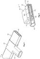
- Fig. 1
- shows a perspective view, broken away on one side, of an electrically insulated base conductor, the electrical insulation of which is removed in the region of a plug-in connection device which can be provided on the base conductor;
- Fig. 2
- shows a perspective view, broken away on two sides, of a carrier strip with two electrical plug-in connection devices, provided integrally thereon, for the base conductor;
- Fig. 3
- shows a depiction of the base conductor which is similar to
Fig. 1 , wherein a plug-in connection device is fixed on the base conductor in the region which is freed from the insulation (inventive current transport mechanism); - Fig. 4
- shows a depiction of the current transport mechanism which is similar to
Fig. 3 , wherein the current transport mechanism has a jacket in the region of its plug-in connection device; - Fig. 5
- shows a perspective view, broken away on one side, of the current transport mechanism from
Fig. 4 , wherein the current transport mechanism is depicted as sectioned in a region of its jacketed plug-in connection device; - Fig. 6
- shows a sectioned lateral view of a first exemplary embodiment of an inventive current transport mechanism with a base conductor and a terminal conductor provided thereon, wherein the base conductor and the terminal conductor are formed with the same thickness;
- Fig. 7
- shows a sectioned lateral view of a second exemplary embodiment of the current transport mechanism, wherein the base conductor is formed thicker than the terminal conductor;
- Fig. 8
- shows a sectioned lateral view of a third exemplary embodiment of the current transport mechanism with a base conductor and two terminal conductors provided thereon, wherein the base conductor is formed thicker than the terminal conductors;
- Fig. 9
- shows a perspective view, broken away on two sides, of a fourth exemplary embodiment of the current transport mechanism, wherein a plug-in connection device which is exposed out of a predetermined contact region is depicted;
- Fig. 10
- shows a sectioned lateral view of a fifth exemplary embodiment of the current transport mechanism which is similar to
Fig. 6 , with an aluminium-based base conductor and a predetermined contact region or silver-plated, copper-based terminal conductor; - Fig. 11
- shows a sectioned lateral view of a sixth exemplary embodiment of the current transport mechanism which is similar to
Fig. 6 , with an aluminium-based base conductor and a predetermined contact region or silver-plated, aluminium-based terminal conductor; - Fig. 12
- shows a sectioned lateral view of a seventh exemplary embodiment of the current transport mechanism which is similar to
Fig. 10 , with predetermined contact regions provided on two sides or silver-plated terminal conductors; - Fig. 13
- shows a sectioned lateral view of an eighth exemplary embodiment of the current transport mechanism which is similar to
Fig. 11 , with predetermined contact regions provided on two sides or silver-plated terminal conductors; - Fig. 14
- shows a sectioned lateral view of a ninth exemplary embodiment of the current transport mechanism, with predetermined contact regions provided on two sides or silver-plated terminal conductors, which are formed of variable thickness;
- Fig. 15
- shows a sectioned lateral view of a tenth exemplary embodiment of the current transport mechanism, wherein the current transport mechanism is formed as a bilayer current transport mechanism; and
- Fig. 16
- shows a perspective view, broken away on two sides, of an eleventh exemplary embodiment of the current transport mechanism, wherein three plug-in connection devices which are exposed out of predetermined contact regions (boxes) are depicted.
- The invention is explained in greater detail hereinafter in a cursory manner using exemplary embodiments of an embodiment of a first variant (
Figs. 1-5 ) and three exemplary embodiments (Figs. 6-8 and Figs. 9 ,10, 12 ,14-16 andFigs. 11, 13 ) of a second variant of an inventive (vehicle)current transport mechanism 1, such as an (energy/power)backbone 1, an (energy/power)bus bar 1. However, the invention is not limited to such variants, embodiments and/or the exemplary embodiments which are explained hereinafter, but is of a more fundamental nature, such that it can be applied to all current transport mechanisms in accordance with the invention, e.g. for anappliance 0, amachine 0, a conveyingmeans 0, asystem 0, aunit 0, etc., e.g. for a non-automotive industry. - Only the sections which are necessary for understanding the invention are depicted in the drawings. Although the invention is more closely described and illustrated in detail by preferred exemplary embodiments, the invention is not restricted by the disclosed exemplary embodiments. Other variations can be derived herefrom without departing from the scope of protection of the invention.
- A manufacture and a structure of the embodiment of the first variant of the invention is explained in greater detail hereinafter using
Figs. 1-5 . In this case, an elongated or rod-shaped electrical or electrically (-rigidly)mechanical base conductor 10, such as an actual (current)bar 10, preferably made of aluminium or an aluminium alloy, is surmised. Of course, another material can be used. Thebase conductor 10 has anelectrical insulation 30, which preferably completely surrounds it in the circumferential direction and which in particular is made of a preferably moulded-in plastic. In this case, in contrast to the depiction, the two end faces of thebase conductor 10 can also have theelectrical insulation 30. In the latter case, thebase conductor 10 is initially completely encapsulated or electrically insulated. - For the
current transport mechanism 1, a region is initially localised on theelectrical insulation 30 of thebase conductor 10, in which region an initially separate, electrical or electrically-rigidly mechanical plug-in connection device 100 (Fig. 2 ) is intended to be fixedly provided or assembled on the base conductor 10 (Fig. 1 ). The preferably integral one-piece or one-part plug-inconnection device 100 is preferably formed as a (faston)tab contact device 100 or a pin contact device; a bushing contact device can of course also be used. In this case, the plug-inconnection device 100 is preferably manufactured from aluminium or copper or an aluminium alloy or a copper alloy, in particular stamped or stamped and bent. - The plug-in
connection device 100 has acontact section 110 for assembling the plug-inconnection device 100 on thebase conductor 10 and a plug-incontact section 120, by means of which the plug-inconnection device 100 can be electrically contacted by an electrical or electrically-rigidly mechanical mating plug-in connection device 9 (cf.Figs. 12, 13 ,16 ). The plug-inconnection device 100 can be completely or selectively coated, e.g. withsilver 222,tin 222, etc. In the case of a selective coating, only the plug-incontact section 120 is also, where applicable, selectively coated on one side or on two sides. The plug-inconnection device 100 is preferably provided by acarrier strip 90, e.g. on a reel. - Temporally after the localisation of the region for the plug-in
connection device 100, theelectrical insulation 30 is substantially completely removed from thebase conductor 10 in this region (first step,Fig. 1 ), e.g. by cutting open and extracting theelectrical insulation 30. The initial result is an exposedregion 11 on thebase conductor 10 or of thebase conductor 10 under a through-recess 310 orrecess 310 in theelectrical insulation 30. Temporally thereafter or shortly before the second step, theregion 11 of thebase conductor 10 is preferably deoxidised. - In the second step which temporally follows, the plug-in
connection device 100 is connected to thebase conductor 10 in one part, materially/adhesively in one piece or in one piece (Fig. 3 ), i.e. attached thereon, which, for example, can take place by adhesion, soldering, welding, clinching, etc. For this purpose, themechanical contact section 110 of the plug-inconnection device 100 is fixed on thebase conductor 10 in theregion 11. The plug-incontact section 120 of the plug-inconnection device 100 then protrudes or projects, e.g. laterally, upwardly or downwardly from thebase conductor 10. - Consequently, the inventive
current transport mechanism 1 is obtained. Of course, these steps can be performed repeatedly per se if a plurality of plug-inconnection devices 100 are intended to be fixedly connected to thebase conductor 10. Temporally after the plug-inconnection device 100 has been fixed to thebase conductor 10, a preferably moulded-injacket 40 can be provided over the, where applicable, relevant plug-in connection device 100 (third step). In this case, thejacket 40 can be partially formed as aconnector housing 42 for the mating plug-inconnection device 9. - A manufacture and a structure of the three embodiments of the second variant of the invention is explained in greater detail hereinafter using
Figs. 6-16 . In this case, an elongated or rod-shaped electrical or electrically (-rigidly)mechanical conductor 10/20, such as an actual (current) bar 10/20, preferably made of aluminium and/or copper or an aluminium alloy and/or a copper alloy, is surmised. Of course, another material or other materials or combinations can be used. Theelectromechanical conductor 10/20 has anelectrical insulation 30, which preferably completely surrounds it in the circumferential direction and which in particular is made of a preferably moulded-in plastic (seeFigs. 9-16 ). In this case, the two end faces of theconductor 10/20 preferably also have theelectrical insulation 30, i.e. theconductor 10/20 is initially completely encapsulated or electrically insulated. - The
electromechanical conductor 10/20 is preferably formed or developed from a metallic composite product or only one single metallic product. In this case, theelectromechanical conductor 10/20 can comprise an elongated,electromechanical base conductor 10 and an elongated, electromechanical terminal conductor 20 which is arranged parallel thereto. - In a first case, (preferably composite products,Figs. 6-10 ,12 ,14, 15 ) thebase conductor 10 has a first metallic product, in particular an aluminium product, and the terminal conductor 20 has a second metallic product, in particular a copper-based product. - In a second case (
Figs. 11, 13 ), thebase conductor 10 and the terminal conductor 20 have the same metallic product, in particular an aluminium product. In this case, the terminal conductor 20 and thebase conductor 10 are preferably formed together, wherein the two of them do not obviously differ from each other, or thebase conductor 10 continuously passes into the terminal conductor 20, which is shown inFigs. 11, 13 , for example. A differentiation can then be made, firstly irrespective of differences in thickness, shape, etc., on the basis of dimensions. - In both cases, the terminal conductor 20 can (as a predetermined contact region 200 or even merely as a plug-in connection device (202), see below) be coated on one side (Figs. 6, 7 ,10, 11 ) or on both sides (Figs. 8 ,12-16 ), possibly partially, for at least one potential plug-in connection device 202 which should be set up later, which coating can take place withsilver 222,tin 222, etc., for example. - The terminal conductor 20 can be formed, just like the
base conductor 10, as an elongated or rod-shaped, electrical or electrically(-rigidly) mechanical terminal conductor 20, which is formed monolithically, integrally, simply, materially/adhesively in one piece or in one piece with thebase conductor 10. In this case, at thebase conductor 10, the terminal conductor 20 can be provided or established in a blank (1) for thecurrent transport mechanism 1, being substantially the same length as thebase conductor 10. It is of course possible to provide the terminal conductor 20 only in sections at thebase conductor 10, such that the terminal conductor 20 can also be formed as at least one predetermined, electrical or electrically-rigidly mechanical contact region 200 or even merely as at least one electrical or electrically-rigidly mechanical plug-in connection device 202 (see both hereinafter). - In the blank (1) for the
current transport mechanism 1, theelectromechanical conductor 10/20 or thebase conductor 10 and at least the terminal conductor 20, and thus the at least one predetermined contact region 200 (where applicable of the at least one terminal conductor 20) or the at least one plug-in connection device 202 (where applicable of the at least one predetermined contact region 200 and/or of a terminal conductor 20) are provided with theelectrical insulation 30 at least at the only two comparatively large sides (running in the longitudinal direction and in the transverse direction). Preferably, the blank (1) is completely provided with theelectrical insulation 30. - For manufacturing a
current transport mechanism 1, a position of a plug-in connection device 202 which should be developed in the blank (1) is initially determined at the blank (1) of the current transport mechanism 1 (first step). In this case, at least one position in at least one terminal conductor 20, in at least one predetermined contact region 200 and/or at least one (still electrically insulated) plug-in connection device 202, for the at least one plug-in connection device 202 which should be selected, can be selected. This at least one position can be selected, for example, from a plurality of positions which are marked at/in the electrical insulation 30 (cf.Fig. 9 ). - Temporally thereafter, at least one electrical or electrically-rigidly mechanical plug-in connection device 202 is exposed out of the blank (1) of the resulting
current transport mechanism 1, in particular cut free or punched out (second step). In this case, possibly only theelectrical insulation 30 is removed from the blank (1) in a relevant region. Furthermore, the plug-in connection device 202 can be formed thereon subsequently or substantially simultaneously. The latter preferably takes place by providing two slots (only one slot is necessary at one longitudinal end) in the longitudinal direction to the right and left of the resulting plug-in connection device 202 (cf.Fig. 9 ). An electrical or electrically-rigidly mechanical mating plug-inconnection device 9 can later be plugged on the resulting (faston) tab contact device 202 or pin contact device 202 of the actualcurrent transport mechanism 1. - The configurations of the exemplary embodiments of the
current transport mechanisms 1 depicted inFigs. 6 to 16 are explained in greater detail hereinafter in a cursory manner. - In the case ofFig. 6 , thebase conductor 10 and the terminal conductor 20 or the predetermined contact region 200 are formed substantially with the same thickness, a longitudinal side of thebase conductor 10 and a longitudinal side of the terminal conductor 20 being connected to each other in acomposite contact region 210. The plug-in connection device 202 was exposed with its plug-in contact section 220 out of the terminal conductor 20 or the predetermined contact region 200, which also applies forFigs. 7 and 8 . - In the case of
Fig. 7 , the terminal conductor 20 is thinner than thebase conductor 10 and is provided at an outer side, having a large surface area, of thebase conductor 10, the terminal conductor 20 being embedded with itscomposite contact region 210 in the base conductor 10 (the terminal conductor 20 preferably partially overlaps thebase conductor 10 in the transverse direction).Thecomposite contact region 210 is not only established longitudinally but also transversely between the terminal conductor 20 and thebase conductor 10. -Fig. 8 shows abase conductor 10 with two terminal conductors 20 which are provided thereon and which are similar toFig. 7 , thebase conductor 10 being formed thicker than the terminal conductors 20, which are fixed thereon, being located diagonally opposite each other with regard to a cross-section of thebase conductor 10. - In
Figs. 6-8 , the respective plug-in contact section 220 of the relevant plug-in connection device 202 protrudes outwardly from thecurrent transport mechanism 1 and is accessible from five translatory directions, provided there is enough space in both longitudinal directions. The relevant plug-in contact section 220 is not accessible from only one transverse direction.Figs. 6-8 do not show acoating 222 of the respective plug-in contact sections 220 of the plug-in connection devices 202 or the plug-in connection devices 202. In the exemplary embodiments ofFigs. 6-8 , which each show the first embodiment, such an embodiment can of course be applied. - A transition to the second embodiment is depicted in
Fig. 7 using dashes (this can also be applied inFigs. 6 and 8 ). In the second embodiment, the stripped plug-in contact section 220 of the relevant plug-in connection device 202 is embedded in thecurrent transport mechanism 1, the plug-in contact section 220 only being accessible from three translatory directions (the front, above, underneath). This is also shown inFig. 9 , which moreover shows a coated terminal conductor 20 (coating 222)or a coated, predetermined contact region 200 and a coated plug-in connection device 202 or a coated plug-in contact section 220.Fig. 16 shows three plug-in connection devices 202 or plug-in contact sections 220 of this kind, which are each contacted by a mating plug-inconnection device 9. - The following
Figs. 10-15 show cross-sections ofcurrent transport mechanisms 1 at a distance in its established plug-in connection devices 202 or plug-in contact sections 220; an, as before, fully circumferentially electrically insulated cross-section of the relevantcurrent transport mechanism 1 is depicted in each case. In this case, the respectivecurrent transport mechanism 1 can have at least one exposed plug-in connection device 202 or one exposed plug-in contact section 220. This is highlighted inFigs. 12 and 13 by means of in each case a mating plug-inconnection device 9, which is plugged onto a plug-in connection device 202 which is not depicted or a plug-in contact section 220 which is not depicted. -
Fig. 10 shows an aluminium-basedbase conductor 10 of acurrent transport mechanism 1, at which one single copper-based terminal conductor 20 is provided laterally (composite product). In this case, the terminal conductor 20 is coated on both sides, in particular withsilver 222. -Fig. 11 shows a configuration which is similar toFig. 10 , but wherein the terminal conductor 20 and thebase conductor 10 are both aluminium-based. In this case, it is preferable that the terminal conductor 20 is manufactured simultaneously with the base conductor 10 (extrusion, rolling, casting, etc.). Thebase conductor 10 and the terminal conductor 20 are preferably formed monolithically, integrally and/or simply. -
Fig. 12 shows a depiction of thecurrent transport mechanism 1 which is similar toFig. 10 , but wherein two double-sided, copper-based terminal conductors 20, which are preferably coated withsilver 222, are provided at the transverse sides of the aluminium-basedbase conductor 10. - Furthermore,Fig. 13 shows a depiction of thecurrent transport mechanism 1 which is similar toFig. 11 , wherein two double-sided, aluminium-based terminal conductors 20, which are preferably coated withsilver 222, are formed at the transverse sides of the also aluminium-basedbase conductor 10. - In the exemplary embodiments of
Figs. 10-13 , therelevant conductors 10, 20 can be formed with the same thickness. By way of example,Fig. 14 highlights that this does not have to be the case with two terminal conductors 20 at asingle base conductor 10, which terminal conductors 20 are of varying thickness and are preferably coated withsilver 222. In this case, the relevant terminal conductor 20 is preferably thinner (left inFig. 14 ) than thebase conductor 10, or preferably has the same thickness (left inFig. 14 ) as thebase conductor 10. - Furthermore, it can be advantageous in all exemplary embodiments that acoating 222 reaches up to thebase conductor 10 and where applicable slightly overlaps it (cf.Figs. 10, 12 ,14, 15 ). -
Fig. 14 shows acurrent transport mechanism 1 as a bilayercurrent transport mechanism 1 with twoelectromechanical conductors 10/20, 10/20 which are electrically insulated from each other. In this case, preferably only one single layer of anelectrical insulation 30 is provided between the twobase conductors 10. Furthermore, it is preferable that a terminal conductor 20 or a predetermined contact region 200 is provided at therelevant base conductor 10 at only one longitudinal side. A different number ofelectromechanical conductors 10/20, 10/20, ... is of course possible (a multilayer current transport mechanism 1). - A jacket (40, 42) according to the first variant of the invention can of course be applied to all exemplary embodiments.
Claims (15)
- A vehicle current transport mechanism (1), in particular for a motor vehicle, with an elongated, electromechanical base conductor (10), characterised in that
the base conductor (10) comprises at least one electrically-rigidly mechanical plug-in connection device (100, 202) which is connected thereto in an electrically-rigidly mechanical manner, and which in turn can be electrically contacted by an electrically-rigidly mechanical mating plug-in connection device (9). - The vehicle current transport mechanism (1) according to the preceding claim, characterised in that the electrically-rigidly mechanical connection is formed monolithically, integrally, simply, materially/adhesively in one piece, in one piece and/or in one part between the base conductor (10) and the plug-in connection device (100, 202).
- The vehicle current transport mechanism (1) according to any one of the preceding claims, characterised in that:• the plug-in connection device (100) has a mechanical contact section (110), by means of which the plug-in connection device (100) is fixed on the base conductor (10) ;• the plug-in connection device (202) has a composite contact region (210), by means of which the plug-in connection device (100) is formed with the base conductor (10) ;• the plug-in connection device (100, 202) has a plug-in contact section (120, 220) which can be electrically and mechanically contacted by the mating plug-in connection device (9); and/or• the vehicle current transport mechanism (1) is further formed as a current transport mechanism (1) according to any one of the following claims.
- The current transport mechanism (1), in particular current bar (1), backbone (1) or bus bar (1) for the automotive industry, characterised in that
the current transport mechanism (1) has an elongated, electromechanical base conductor (10) with an electrical insulation (30) surrounding it in the circumferential direction, wherein
the electrical insulation (30) has at least one through-recess (310) and the base conductor (10) is electrically contacted by a plug-in connection device (100) in a region (11) of the through-recess (310). - The current transport mechanism (1) according to the preceding claim, characterised in that the plug-in connection device (100) comprises a mechanical contact section (110) and a plug-in contact section (120), wherein
the mechanical contact section (110) electrically contacts the base conductor (10) in the region (11) of the through-recess (310) and the plug-in contact section (120) protrudes from the base conductor (10). - The current transport mechanism (1) according to any one of the preceding claims, characterised in that the current transport mechanism (1) has a jacket (410) in a region of the plug-in connection device (100), wherein
the jacket (410) is preferably formed such that it seals the plug-in contact section (120) of the plug-in connection device (100) in a fluid-tight manner, in particular in a water-tight manner or water-vapour-tight manner, from the base conductor (10) in the region (11) of the through-recess (310) . - The current transport mechanism (1) according to any one of the preceding claims, characterised in that:• the base conductor (10) is formed as an electrically-rigidly mechanical base conductor (10);• the plug-in connection device (100) is formed as a stamped part or a stamped bent part;• the plug-in connection device (100) is formed as a tab contact device (100) or a pin contact device (100).• the plug-in connection device (100) is connected to the base conductor (10) in one part, materially/adhesively in one piece or in one piece;• the base conductor (10) is contacted by the plug-in connection device (100) in an electrically-rigidly mechanical manner in the region (11) of the through-recess (310);• the base conductor (10) is deoxidised in the region (11) of the through-recess (310);• the jacket (410) is formed as an overmould (410);• the jacket (410) is formed in sections as a connector housing (412) for a mating plug-in connection device (9); and/or• the current transport mechanism (1) is further formed as a vehicle current transport mechanism (1) according to any one of the preceding claims.
- The current transport mechanism (1), in particular current bar (1), backbone (1) or bus bar (1) for the automotive industry, characterised in that
the current transport mechanism (1) has an elongated, electromechanical conductor (10/20) with an electrical insulation (30) surrounding it in the circumferential direction, wherein
the current transport mechanism (1) has at least one plug-in connection device (202) which is exposed out of the electrical insulation (30) and the electromechanical conductor (10/20). - The current transport mechanism (1) according to the preceding claim, characterised in that the current transport mechanism (1) has at least one predetermined contact region (200) at the outer edge, out of which the plug-in connection device (202) can be exposed, and
the electromechanical conductor (10/20), in particular an electromechanical terminal conductor (20) of the electromechanical conductor (10/20) is preferably coated in the region of the predetermined contact region (200). - The current transport mechanism (1) according to any one of the preceding claims, characterised in that
the electromechanical conductor (10/20) of the current transport mechanism (1) is formed from a metallic composite product, in particular an aluminium/copper composite product, or
the electromechanical conductor (10/20) of the current transport mechanism (1) is formed from a single metallic product, in particular an aluminium product. - The current transport mechanism (1) according to any one of the preceding claims, characterised in that the electromechanical conductor (10/20) comprises an elongated, electromechanical base conductor (10) and an elongated, electromechanical terminal conductor (20) which is arranged parallel thereto, wherein
the base conductor (10) has a first metallic product, in particular an aluminium-based product, and the terminal conductor (20) has a second metallic product, in particular a copper-based product, or
the base conductor (10) and the terminal conductor (20) have the same metallic product and are integrally or monolithically formed with each other. - The current transport mechanism (1) according to any one of the preceding claims, characterised in that the current transport mechanism (1) has at least one predetermined contact region (200) at one or both longitudinal sides, or
the current transport mechanism (1) has a terminal conductor (20) at one or both longitudinal sides which extends along a longitudinal section of the base conductor (10), the terminal conductor (20) preferably extending along an entire longitudinal extension of the base conductor (10). - The current transport mechanism (1) according to any one of the preceding claims, characterised in that, with the exception of a coating, a thickness of the plug-in connection device (202) or the terminal conductor (20) is smaller than, the same as or greater than a thickness of the base conductor (10), and/or
the current transport mechanism (1) is formed as a multilayer current transport mechanism (1) with a plurality of electromechanical conductors (10/20, 10/20,...), in particular as a bilayer current transport mechanism (1) with two electromechanical conductors (10/20, 10/20). - The current transport mechanism (1) according to any one of the preceding claims, characterised in that:• the base conductor (10) is formed as an electrically-rigidly mechanical base conductor (10);• the terminal conductor (10) is formed as an electrically-rigidly mechanical terminal conductor (10);• the plug-in connection device (100) is formed as a tab contact device (100) or a pin contact device (100);• the plug-in connection device (202) is formed monolithically, integrally, simply or materially/adhesively in one piece with the base conductor (10); and/or• the current transport mechanism (1) is further formed as a vehicle current transport mechanism (1) according to any one of the preceding claims.
- An entity (0), mechanism (0), module (0), subassembly (0), appliance (0), apparatus (0), machine (0), conveying means (0), transport means (0), system (0) or unit (0), characterised in that
the entity (0), the device (0), the module (0), the subassembly (0), the appliance (0), the apparatus (0), the machine (0), the conveying means (0), the transport means (0), the system (0) or the unit (0) has a vehicle current transport mechanism (1) or a current transport mechanism (1) according to any one of the preceding claims.
Applications Claiming Priority (1)
| Application Number | Priority Date | Filing Date | Title |
|---|---|---|---|
| DE102016124963.7A DE102016124963A1 (en) | 2016-12-20 | 2016-12-20 | Power transport device, in particular electrical or electromechanical busbar |
Publications (1)
| Publication Number | Publication Date |
|---|---|
| EP3339104A1 true EP3339104A1 (en) | 2018-06-27 |
Family
ID=60923210
Family Applications (1)
| Application Number | Title | Priority Date | Filing Date |
|---|---|---|---|
| EP17207212.6A Pending EP3339104A1 (en) | 2016-12-20 | 2017-12-14 | A current transport mechanism, in particular an electrical or electromechanical current bar |
Country Status (5)
| Country | Link |
|---|---|
| US (1) | US10793007B2 (en) |
| EP (1) | EP3339104A1 (en) |
| JP (1) | JP7048294B2 (en) |
| CN (1) | CN108206443B (en) |
| DE (1) | DE102016124963A1 (en) |
Cited By (1)
| Publication number | Priority date | Publication date | Assignee | Title |
|---|---|---|---|---|
| EP4275964A1 (en) * | 2022-05-12 | 2023-11-15 | LEONI Bordnetz-Systeme GmbH | Device for electrical power distribution for a motor vehicle |
Families Citing this family (5)
| Publication number | Priority date | Publication date | Assignee | Title |
|---|---|---|---|---|
| DE102017102130B4 (en) | 2017-02-03 | 2019-03-14 | Lisa Dräxlmaier GmbH | Housing element, electrical line assembly and manufacturing method thereof |
| JP6874555B2 (en) * | 2017-06-16 | 2021-05-19 | 株式会社オートネットワーク技術研究所 | Busbar and wiring module with the busbar |
| US10177513B1 (en) * | 2017-12-28 | 2019-01-08 | Lear Corporation | Bus bar assembly with a system to form and secure connections to the terminals on a bus bar |
| DE102018219466A1 (en) | 2018-11-14 | 2020-05-14 | Audi Ag | Method for producing a current guiding device, junction box for a vehicle battery and motor vehicle |
| JP7123514B2 (en) * | 2020-06-17 | 2022-08-23 | 矢崎総業株式会社 | conductive structure |
Citations (6)
| Publication number | Priority date | Publication date | Assignee | Title |
|---|---|---|---|---|
| EP0028791A1 (en) * | 1979-11-08 | 1981-05-20 | COMPAGNIE INDUSTRIELLE DES TELECOMMUNICATIONS CIT-ALCATEL S.A. dite: | Electrical bus-bar |
| US20010036766A1 (en) * | 1999-12-27 | 2001-11-01 | Mitsubonu Katoh | Interlayer connection structure |
| US6476705B1 (en) * | 1996-11-22 | 2002-11-05 | Audio Ohm Di Tonani Caterina Ecs.N.C. | Current distribution device |
| EP1313179A2 (en) * | 2001-11-20 | 2003-05-21 | Fci | Press-fit bus bar for distributing power |
| DE102010007250A1 (en) * | 2010-02-09 | 2011-08-11 | Pollmann Elektrotechnik GmbH, 59302 | Profile rail system for central distribution of electrical energy, has pole rails arranged in profile rail, and insulation rods designed, such that insulation rods project above pole rails at longitudinal sides in mounted condition |
| EP3101745A1 (en) * | 2015-06-03 | 2016-12-07 | Friedrich Göhringer Elektrotechnik GmbH | Multiphase busbar with improved creepage distance |
Family Cites Families (23)
| Publication number | Priority date | Publication date | Assignee | Title |
|---|---|---|---|---|
| DE3023341A1 (en) * | 1980-06-21 | 1982-01-14 | Daimler-Benz Ag, 7000 Stuttgart | Insulated current conductor for buses, railway carriages etc. - is in form of strip cable with connecting tags for multiple appliance connection |
| JPH0750969B2 (en) * | 1988-05-31 | 1995-05-31 | 矢崎総業株式会社 | Electrical junction box |
| JP2924681B2 (en) * | 1994-12-28 | 1999-07-26 | 住友電装株式会社 | Electrical junction box |
| US5759050A (en) * | 1995-02-15 | 1998-06-02 | Sumitomo Wiring Systems, Ltd. | Electrical connection construction between electrical connection box and electronic circuit unit |
| FR2735289B1 (en) * | 1995-06-09 | 1997-08-22 | Schneider Electric Sa | CONNECTION METHOD AND DEVICE FOR SET OF OVER-MOLDED BARS |
| US5785542A (en) * | 1996-02-15 | 1998-07-28 | Qbc, Inc. | Electrical distribution system having an improved bus coupler |
| JP2001209019A (en) * | 2000-01-25 | 2001-08-03 | Fujitsu Ltd | Acoustooptical variable wavelength te/tm mode converter and variable wavelength light beam filter using same |
| JP2002027636A (en) * | 2000-07-04 | 2002-01-25 | Sumitomo Wiring Syst Ltd | Circuit unit for high-voltage electrical junction box |
| US7354280B2 (en) * | 2006-08-08 | 2008-04-08 | Deere & Company | Modular power distribution system |
| CN101510655A (en) * | 2009-03-20 | 2009-08-19 | 贵州航天电器股份有限公司 | Feeding structure of power supply |
| DE102009024935A1 (en) * | 2009-06-08 | 2010-12-09 | Siemens Aktiengesellschaft | Production of a busbar with a plurality of tapping contacts made of a particularly completely insulated and of a completely galvanically galvanized flat profile rail |
| GB0910824D0 (en) * | 2009-06-23 | 2009-08-05 | Gen Dynamics United Kingdom Lt | Vehicle power and signal distribution system |
| KR100977089B1 (en) * | 2009-09-08 | 2010-08-19 | 태인전력시스템(주) | Bus bar and method for manufacturing bus bar |
| DE102010002950A1 (en) * | 2010-03-17 | 2011-09-22 | Robert Bosch Gmbh | CIRCUIT ARRANGEMENT AND ASSOCIATED CONTROL UNIT FOR A MOTOR VEHICLE |
| CN202205483U (en) * | 2011-08-19 | 2012-04-25 | 国电南瑞科技股份有限公司 | Glue sealing type laminated mother row |
| CN102592712B (en) * | 2012-03-23 | 2014-02-26 | 株洲博雅科技股份有限公司 | Method for preparing integral type multi-branch structure copper-bus busbar and busbar |
| DE102014004432A1 (en) * | 2013-04-04 | 2014-10-09 | Lisa Dräxlmaier GmbH | Electrical conduit device, in particular for a motor vehicle |
| CN203326319U (en) * | 2013-04-22 | 2013-12-04 | 苏州西典机电有限公司 | Flexible connection mechanism for laminated mother board |
| CN203883271U (en) * | 2014-05-22 | 2014-10-15 | 苏州西典机电有限公司 | Novel aminated busbar |
| CN204178734U (en) * | 2014-10-25 | 2015-02-25 | 广东顺科通信设备实业有限公司 | A kind of uninterrupted power supply busbar |
| EP3051635B1 (en) * | 2015-01-30 | 2018-01-17 | TE Connectivity Germany GmbH | Electric contact means and electrical cable assembly for the automotive industry |
| DE202015104023U1 (en) * | 2015-07-31 | 2016-11-03 | Rogers Germany Gmbh | conductor rail |
| CN205543582U (en) * | 2016-03-28 | 2016-08-31 | 乐清市高科环保电子有限公司 | Multiaspect board plug -in type busbar |
-
2016
- 2016-12-20 DE DE102016124963.7A patent/DE102016124963A1/en active Pending
-
2017
- 2017-12-14 EP EP17207212.6A patent/EP3339104A1/en active Pending
- 2017-12-15 JP JP2017240106A patent/JP7048294B2/en active Active
- 2017-12-20 CN CN201711384093.2A patent/CN108206443B/en active Active
- 2017-12-20 US US15/848,898 patent/US10793007B2/en active Active
Patent Citations (6)
| Publication number | Priority date | Publication date | Assignee | Title |
|---|---|---|---|---|
| EP0028791A1 (en) * | 1979-11-08 | 1981-05-20 | COMPAGNIE INDUSTRIELLE DES TELECOMMUNICATIONS CIT-ALCATEL S.A. dite: | Electrical bus-bar |
| US6476705B1 (en) * | 1996-11-22 | 2002-11-05 | Audio Ohm Di Tonani Caterina Ecs.N.C. | Current distribution device |
| US20010036766A1 (en) * | 1999-12-27 | 2001-11-01 | Mitsubonu Katoh | Interlayer connection structure |
| EP1313179A2 (en) * | 2001-11-20 | 2003-05-21 | Fci | Press-fit bus bar for distributing power |
| DE102010007250A1 (en) * | 2010-02-09 | 2011-08-11 | Pollmann Elektrotechnik GmbH, 59302 | Profile rail system for central distribution of electrical energy, has pole rails arranged in profile rail, and insulation rods designed, such that insulation rods project above pole rails at longitudinal sides in mounted condition |
| EP3101745A1 (en) * | 2015-06-03 | 2016-12-07 | Friedrich Göhringer Elektrotechnik GmbH | Multiphase busbar with improved creepage distance |
Cited By (1)
| Publication number | Priority date | Publication date | Assignee | Title |
|---|---|---|---|---|
| EP4275964A1 (en) * | 2022-05-12 | 2023-11-15 | LEONI Bordnetz-Systeme GmbH | Device for electrical power distribution for a motor vehicle |
Also Published As
| Publication number | Publication date |
|---|---|
| CN108206443A (en) | 2018-06-26 |
| CN108206443B (en) | 2022-07-08 |
| US10793007B2 (en) | 2020-10-06 |
| JP2018110112A (en) | 2018-07-12 |
| DE102016124963A1 (en) | 2018-06-21 |
| JP7048294B2 (en) | 2022-04-05 |
| US20180170189A1 (en) | 2018-06-21 |
Similar Documents
| Publication | Publication Date | Title |
|---|---|---|
| EP3339104A1 (en) | A current transport mechanism, in particular an electrical or electromechanical current bar | |
| US10096913B2 (en) | Electric wire with terminal metal fitting | |
| US9263808B2 (en) | Connection structural body, connector and method of manufacturing connection structural body | |
| US9070988B2 (en) | Structure and method for connection of connector terminal | |
| US9608339B2 (en) | Crimped terminal attached aluminum electric wire | |
| WO2013088987A1 (en) | Relay terminal | |
| US9065188B2 (en) | Electrical connection | |
| CN109921244B (en) | Electrical busbar | |
| US9666956B2 (en) | Minute current crimping terminal and minute current wire harness | |
| EP2831953B1 (en) | Fuse end cap with crimpable terminal | |
| US9054435B2 (en) | Conversion terminal device and method for coupling dissimilar metal electrical components | |
| JP2017084600A (en) | Wire with terminal and manufacturing method of wire with terminal | |
| JP5979427B2 (en) | conductor | |
| JP2008011677A (en) | Electric connection box | |
| CN104823329A (en) | Method for producing electrically conductive connection between electrical line and electrically conductive component, and module produced according to method | |
| US10164350B2 (en) | Terminal attached wire | |
| US20210376531A1 (en) | Shielded electrical connector assembly and method of manufcturing same | |
| CN101118792B (en) | Co-axial cable component and manufacturing method thereof | |
| CN113228420A (en) | Method for producing a connector for electrical equipment, connector and connection of a connector to a cable | |
| WO2013088992A1 (en) | Relay terminal and connection structure of electrical wire and terminal | |
| JP7144286B2 (en) | Wires and wire bundles | |
| JP2007244145A (en) | Joint connector | |
| JP6090126B2 (en) | Battery terminal | |
| JP2007215373A (en) | Junction box for automobile | |
| JP2001333519A (en) | Circuit body and junction box housing the circuit body |
Legal Events
| Date | Code | Title | Description |
|---|---|---|---|
| PUAI | Public reference made under article 153(3) epc to a published international application that has entered the european phase |
Free format text: ORIGINAL CODE: 0009012 |
|
| STAA | Information on the status of an ep patent application or granted ep patent |
Free format text: STATUS: THE APPLICATION HAS BEEN PUBLISHED |
|
| AK | Designated contracting states |
Kind code of ref document: A1 Designated state(s): AL AT BE BG CH CY CZ DE DK EE ES FI FR GB GR HR HU IE IS IT LI LT LU LV MC MK MT NL NO PL PT RO RS SE SI SK SM TR |
|
| AX | Request for extension of the european patent |
Extension state: BA ME |
|
| STAA | Information on the status of an ep patent application or granted ep patent |
Free format text: STATUS: REQUEST FOR EXAMINATION WAS MADE |
|
| 17P | Request for examination filed |
Effective date: 20181221 |
|
| RBV | Designated contracting states (corrected) |
Designated state(s): AL AT BE BG CH CY CZ DE DK EE ES FI FR GB GR HR HU IE IS IT LI LT LU LV MC MK MT NL NO PL PT RO RS SE SI SK SM TR |
|
| STAA | Information on the status of an ep patent application or granted ep patent |
Free format text: STATUS: REQUEST FOR EXAMINATION WAS MADE |
|
| STAA | Information on the status of an ep patent application or granted ep patent |
Free format text: STATUS: EXAMINATION IS IN PROGRESS |
|
| 17Q | First examination report despatched |
Effective date: 20220426 |