EP3337874B1 - Verfahren zum betrieb eines suspensionsblasensäulenreaktors - Google Patents
Verfahren zum betrieb eines suspensionsblasensäulenreaktors Download PDFInfo
- Publication number
- EP3337874B1 EP3337874B1 EP16759873.9A EP16759873A EP3337874B1 EP 3337874 B1 EP3337874 B1 EP 3337874B1 EP 16759873 A EP16759873 A EP 16759873A EP 3337874 B1 EP3337874 B1 EP 3337874B1
- Authority
- EP
- European Patent Office
- Prior art keywords
- gas
- settled
- bed
- reactor
- reactor vessel
- Prior art date
- Legal status (The legal status is an assumption and is not a legal conclusion. Google has not performed a legal analysis and makes no representation as to the accuracy of the status listed.)
- Active
Links
Images



Classifications
-
- C—CHEMISTRY; METALLURGY
- C10—PETROLEUM, GAS OR COKE INDUSTRIES; TECHNICAL GASES CONTAINING CARBON MONOXIDE; FUELS; LUBRICANTS; PEAT
- C10G—CRACKING HYDROCARBON OILS; PRODUCTION OF LIQUID HYDROCARBON MIXTURES, e.g. BY DESTRUCTIVE HYDROGENATION, OLIGOMERISATION, POLYMERISATION; RECOVERY OF HYDROCARBON OILS FROM OIL-SHALE, OIL-SAND, OR GASES; REFINING MIXTURES MAINLY CONSISTING OF HYDROCARBONS; REFORMING OF NAPHTHA; MINERAL WAXES
- C10G2/00—Production of liquid hydrocarbon mixtures of undefined composition from oxides of carbon
- C10G2/30—Production of liquid hydrocarbon mixtures of undefined composition from oxides of carbon from carbon monoxide with hydrogen
- C10G2/32—Production of liquid hydrocarbon mixtures of undefined composition from oxides of carbon from carbon monoxide with hydrogen with the use of catalysts
- C10G2/34—Apparatus, reactors
- C10G2/342—Apparatus, reactors with moving solid catalysts
-
- B—PERFORMING OPERATIONS; TRANSPORTING
- B01—PHYSICAL OR CHEMICAL PROCESSES OR APPARATUS IN GENERAL
- B01J—CHEMICAL OR PHYSICAL PROCESSES, e.g. CATALYSIS OR COLLOID CHEMISTRY; THEIR RELEVANT APPARATUS
- B01J8/00—Chemical or physical processes in general, conducted in the presence of fluids and solid particles; Apparatus for such processes
- B01J8/18—Chemical or physical processes in general, conducted in the presence of fluids and solid particles; Apparatus for such processes with fluidised particles
- B01J8/20—Chemical or physical processes in general, conducted in the presence of fluids and solid particles; Apparatus for such processes with fluidised particles with liquid as a fluidising medium
- B01J8/22—Chemical or physical processes in general, conducted in the presence of fluids and solid particles; Apparatus for such processes with fluidised particles with liquid as a fluidising medium gas being introduced into the liquid
-
- C—CHEMISTRY; METALLURGY
- C10—PETROLEUM, GAS OR COKE INDUSTRIES; TECHNICAL GASES CONTAINING CARBON MONOXIDE; FUELS; LUBRICANTS; PEAT
- C10G—CRACKING HYDROCARBON OILS; PRODUCTION OF LIQUID HYDROCARBON MIXTURES, e.g. BY DESTRUCTIVE HYDROGENATION, OLIGOMERISATION, POLYMERISATION; RECOVERY OF HYDROCARBON OILS FROM OIL-SHALE, OIL-SAND, OR GASES; REFINING MIXTURES MAINLY CONSISTING OF HYDROCARBONS; REFORMING OF NAPHTHA; MINERAL WAXES
- C10G2/00—Production of liquid hydrocarbon mixtures of undefined composition from oxides of carbon
- C10G2/30—Production of liquid hydrocarbon mixtures of undefined composition from oxides of carbon from carbon monoxide with hydrogen
- C10G2/32—Production of liquid hydrocarbon mixtures of undefined composition from oxides of carbon from carbon monoxide with hydrogen with the use of catalysts
- C10G2/34—Apparatus, reactors
- C10G2/342—Apparatus, reactors with moving solid catalysts
- C10G2/344—Apparatus, reactors with moving solid catalysts according to the "fluidised-bed" technique
-
- B—PERFORMING OPERATIONS; TRANSPORTING
- B01—PHYSICAL OR CHEMICAL PROCESSES OR APPARATUS IN GENERAL
- B01J—CHEMICAL OR PHYSICAL PROCESSES, e.g. CATALYSIS OR COLLOID CHEMISTRY; THEIR RELEVANT APPARATUS
- B01J2208/00—Processes carried out in the presence of solid particles; Reactors therefor
- B01J2208/00008—Controlling the process
- B01J2208/00548—Flow
-
- B—PERFORMING OPERATIONS; TRANSPORTING
- B01—PHYSICAL OR CHEMICAL PROCESSES OR APPARATUS IN GENERAL
- B01J—CHEMICAL OR PHYSICAL PROCESSES, e.g. CATALYSIS OR COLLOID CHEMISTRY; THEIR RELEVANT APPARATUS
- B01J2208/00—Processes carried out in the presence of solid particles; Reactors therefor
- B01J2208/00008—Controlling the process
- B01J2208/00716—Means for reactor start-up
-
- B—PERFORMING OPERATIONS; TRANSPORTING
- B01—PHYSICAL OR CHEMICAL PROCESSES OR APPARATUS IN GENERAL
- B01J—CHEMICAL OR PHYSICAL PROCESSES, e.g. CATALYSIS OR COLLOID CHEMISTRY; THEIR RELEVANT APPARATUS
- B01J2208/00—Processes carried out in the presence of solid particles; Reactors therefor
- B01J2208/00796—Details of the reactor or of the particulate material
- B01J2208/00893—Feeding means for the reactants
- B01J2208/00911—Sparger-type feeding elements
-
- C—CHEMISTRY; METALLURGY
- C10—PETROLEUM, GAS OR COKE INDUSTRIES; TECHNICAL GASES CONTAINING CARBON MONOXIDE; FUELS; LUBRICANTS; PEAT
- C10G—CRACKING HYDROCARBON OILS; PRODUCTION OF LIQUID HYDROCARBON MIXTURES, e.g. BY DESTRUCTIVE HYDROGENATION, OLIGOMERISATION, POLYMERISATION; RECOVERY OF HYDROCARBON OILS FROM OIL-SHALE, OIL-SAND, OR GASES; REFINING MIXTURES MAINLY CONSISTING OF HYDROCARBONS; REFORMING OF NAPHTHA; MINERAL WAXES
- C10G2300/00—Aspects relating to hydrocarbon processing covered by groups C10G1/00 - C10G99/00
- C10G2300/40—Characteristics of the process deviating from typical ways of processing
- C10G2300/4031—Start up or shut down operations
Definitions
- This invention relates to a method of operating a slurry bubble column reactor.
- the invention relates to a method for starting a slurry bubble column reactor.
- Slurry bubble column reactors have superior heat transfer and temperature equalisation characteristics and also offer high production capacities in a single reactor.
- fine solids typically catalyst particles usually smaller than 200 microns
- a gas stream is typically introduced at or close to the bottom of the slurry bed.
- Slurry bubble column reactors typically operate with the slurry bed in the churn-turbulent hydrodynamic flow regime.
- a different type of three-phase reactor to a slurry bubble column reactor is an ebullating bed reactor.
- Ebullating bed reactors are disclosed for example in re-issued US 2,987,465 (re-issue 25,770).
- a mass of solid particles kept in a state of random motion by an upward flowing liquid phase is described as ebullated.
- Ebullating bed reactors typically operate in the well-mixed hydrodynamic flow regime at much lower gas velocities than slurry bubble column reactors.
- co-currently upward flowing liquid phase and gas phase material contact a mass of solid particles in random motion within the reactor.
- ebullating bed reactors usually employ larger catalyst particles; typically in the range of 100 to 5000 microns, preferably 350 to 3000 microns. It should be noted that in ebullating bed reactors, catalyst fluidisation is largely achieved by the flow of the liquid phase, whereas in slurry bubble column reactors it is largely the flow of gas phase that fluidises the catalyst particles.
- US 6512017 discloses a method of starting up a slurry bubble column reactor, said method including transferring clean molten wax to the reactor, establishing a gas flow through the liquid phase by recycling gas around the reactor, and then transferring a slurry of catalyst particles to the reactor. It further teaches a method a shutting down a slurry bubble column reactor that involves the steps of cutting a fresh syngas supply to the reactor so that the reactor is only operated under recycle, reducing the temperature to within the range of 150°C to 200°C, and then transferring at least a portion of the slurry to an unloading vessel while maintaining gas flow through the reactor. Restarting of the reactor involves reloading of the catalyst slurry into the reactor according to the method followed for a normal reactor start-up.
- It yet further discloses a method of dealing with plant upsets which method includes cutting fresh synthesis gas supply to the reactor so that the reactor is operated under recycle only, reducing the temperature to within the range of 150°C to 200°C, and then transferring at least a portion of the slurry to an unloading vessel while maintaining gas flow through the reactor.
- the reactor is restarted by starting the syngas flow to the reactor, increasing the temperature and then reloading the unloaded catalyst portion back into the reactor.
- It yet further discloses a method of dealing with a failure of a gas recycle system around the reactor said method including stopping fresh synthesis gas feed to the reactor, adding a quenching fluid to the reactor to decrease the temperature while optionally decreasing the pressure of the reactor, maintaining the temperature between 150°C and 200°C, and optionally unloading some catalyst slurry from the reactor.
- the reactor is restarted by starting the recycle gas flow around the reactor until the settled catalyst bed has been re-suspended and the catalyst particles are in a state of fluidisation, whereafter fresh synthesis gas is also introduced.
- EP 2692831 teaches a method of starting up a slurry bubble column Fischer-Tropsch reactor which involves first introducing and recycling an inert gas around the reactor in order to displace other gases and to fluidise the catalyst. In a second step, synthesis gas is introduced and recycled around the reactor to displace the inert gas and to maintain the catalyst in a state of fluidisation. In a final step, the fresh synthesis gas feed to the reactor is gradually increased to steady state operating conditions.
- US 2005/0209351 relates to methods for prevention of and recovery from catalyst bed slumping or settling in a multiphase hydrocarbon synthesis reactor.
- the reactor contains a catalyst bed comprising catalyst particles and a gas injection zone suitable for injecting a reactor gas feed.
- the reactor is equipped with a reactor gas feed supply line and a supplementary gas feed line is connected to the reactor gas feed supply line.
- supplemental gas feed can be activated to prevent slumping of the catalyst bed.
- the gas injection zone be separated from the catalyst bed with a porous plate situated above the gas injection zone to prevent migration of the catalyst particles into the gas injection zone in the event that the bed does slump.
- the prior art teaches start-up of slurry bubble column reactors using generic steps of forming a slurry of catalyst particles in a liquid medium inside a mixing vessel and transferring the slurry to the reactor while maintaining the catalyst in a state of fluidisation inside the reactor by means of a gas feed.
- a gas flow to the reactor be maintained (either via recycling gas around the reactor or gas from an external source) to keep the catalyst particles in suspension, and/or that at least a part of the slurry inventory of the reactor be transferred out of the reactor.
- slurry bubble column reactors In the past decades, commercial slurry bubble column reactors have become bigger in size. In order to increase single reactor capacity, the reactors can have diameters of several meters and the catalyst inventory may comprise hundreds of tons. Furthermore, a method to further increase the production capacity of a slurry bubble column reactor is to increase the catalyst concentration inside the reactor resulting in even higher catalyst loading.
- a method for starting a slurry bubble column reactor that includes a reactor vessel holding a settled or slumped bed of particles and a liquid phase from which the particles have settled, the method including introducing a flow of a re-suspension liquid into the settled or slumped bed to loosen the settled or slumped bed, the introduction of the re-suspension liquid taking place before the introduction of any gas into the settled or slumped bed, or together with feeding of gas into the settled or slumped bed, provided that, if gas is fed together with the re-suspension liquid into the settled or slumped bed before the settled or slumped bed has been loosened, the gas has a superficial gas velocity in the reactor below 10 cm/s; and once the settled or slumped bed has been loosened by at least the re-suspension liquid, passing gas at a superficial gas velocity above 10 cm/s through the liquid phase.
- the gas flows upwardly through the liquid phase, from a low level at which the gas is introduced, e.g. at or near a bottom of the reactor vessel.
- superficial gas velocity or superficial liquid velocity is defined as respectively the gas or liquid volumetric flow rate at the pressure and temperature conditions of the reactor vessel divided by the cross-sectional area of the empty reactor vessel.
- This definition applies to both a cold model setup (e.g. as used in laboratory scale experiments) and to actual installed or designed reactors (e.g. commercial slurry Fischer-Tropsch reactors).
- the particles In normal use or at steady state operation, when a slurry bed is maintained, the particles, i.e. solids, are held in suspension in the liquid phase by turbulence created as gas passes upwardly through the slurry bed. Consequently the particles settle when the gas flow is reduced to low values or stopped.
- the slurry bubble column reactor is in normal use typically, but not necessarily always, operated with the slurry bed inside the reactor vessel in the churn-turbulent flow regime. This flow regime is characterised by a dilute phase consisting of fast-rising large gas bubbles which traverse the slurry bed upwardly virtually in plug flow, and a dense phase comprising liquid phase, solid particles and entrained smaller gas bubbles.
- the mean diameter of the particles determined on a volumetric basis is less than about 200 microns, more preferably less than about 100 microns, most preferably below about 80 microns.
- about 90% of particles on a volume basis have diameters below about 200 microns, more preferably below about 100 microns, most preferably below about 80 microns.
- the settled or slumped bed of particles in the reactor vessel may have a height or depth of at least about 2.5 m, or at least about 5 m, or even at least about 7 m, e.g. at least about 10 m.
- the weight of the solids in such a settled bed may be as high as about 850 000 kg.
- the slurry bubble column reactor has a gas distributor at a low level inside the reactor vessel for introducing gas feed into the reactor vessel.
- the gas distributor in use will typically introduce gas feed at a level that is below or within the settled bed height.
- the Applicant believes that the settled bed is compacted into a plug and that gas introduced at a low level into the reactor vessel displaces this plug upwards. High forces are required to shear the plug. Upward displacement of the plug consequently results in large forces being exerted on reactor internals.
- the plug By feeding a re-suspension liquid, the plug is weakened as a result of the loosening of the settled or slumped bed, so avoiding large forces being exerted on reactor internals.
- the slurry bubble column reactor may be used for Fischer-Tropsch synthesis and may thus be a Fischer-Tropsch slurry bubble column reactor.
- the particles will then include solid Fischer-Tropsch catalyst particles.
- the liquid phase will then typically comprise hydrocarbon liquid product of the Fischer-Tropsch synthesis.
- the re-suspension liquid may be any suitable liquid.
- the re-suspension liquid may stay mainly in the liquid phase after being introduced into the reactor vessel, i.e. into the settled or slumped bed, or the re-suspension liquid may partially or fully vaporise after introduction.
- the re-suspension liquid stays mainly in the liquid phase after being introduced into the settled or slumped bed.
- the re-suspension liquid should preferably be substantially free of substances that have an adverse effect on the performance of the catalyst, e.g. the re-suspension liquid should preferably be substantially free of catalyst poisons.
- the re-suspension liquid preferably is or comprises a product obtained or derived from the Fischer-Tropsch synthesis, such as diesel or wax produced by or derived from the Fischer-Tropsch synthesis.
- the re-suspension liquid has a viscosity of less than about 10 cP, more preferably less than about 4 cP, at the temperature of the settled or slumped bed in the reactor vessel.
- the viscosity of the liquid phase in the slurry bubble-column reactor vessel should also be considered.
- the method therefore includes, prior to the introduction of the flow of the re-suspension liquid, ensuring that the liquid phase in the reactor is at a temperature such that the liquid phase has a viscosity of less than about 10 cP, preferably less than about 4 cP. This may include heating the reactor vessel, i.e. contents of the reactor vessel.
- the liquid phase typically includes waxy hydrocarbon products of the Fischer-Tropsch synthesis.
- the reactor vessel is then typically heated to a temperature of at least about 150°C prior to the introduction of the re-suspension liquid. Should the reactor vessel cool down too much, where the temperature approaches the congealing point of Fischer-Tropsch wax for example, it is possible to have a sufficiently high viscosity to cause higher up-lift forces compared to those observed when lower viscosity liquids are used. It is therefore recommended to prevent excessive cooling of the reactor vessel during shut-down periods.
- the flow of re-suspension liquid may be introduced into the settled or slumped bed with any suitable fluid introduction means, such as a distributor or sparger.
- the fluid introduction means is designed uniformly to distribute the re-suspension liquid across a reactor vessel cross section.
- the volume of the re-suspension liquid introduced into the settled or slumped bed prior to the introduction of gas at a superficial velocity of above 10 cm/s is at least about 5% of an interparticle volume of the settled or slumped bed, more preferably at least about 15% of the interparticle volume of the settled or slumped bed and most preferably at least about 30% of the interparticle volume of the settled or slumped bed.
- the slumped or settled bed is thus considered to be loosened by the re-suspension liquid, or by a combination of the re-suspension liquid and gas at a superficial gas velocity below 10 cm/s, when the volume of re-suspension liquid fed into the settled or slumped bed is at least about 5% of the interparticle volume of the settled or slumped bed, more preferably at least about 15% of the interparticle volume of the settled or slumped bed and most preferably at least about 30% of the interparticle volume of the settled or slumped bed.
- the flow of the re-suspension liquid introduced into the settled or slumped bed has a superficial liquid velocity in the reactor vessel that is greater than the minimum fluidisation velocity of the particles of the settled or slumped bed in the liquid phase in the reactor vessel.
- the superficial liquid velocity of the re-suspension liquid is determined by dividing the total liquid volumetric flow of the re-suspension liquid by the cross sectional area of the reactor vessel.
- the flow of the re-suspension liquid is preferably introduced at a superficial liquid velocity in the reactor vessel of at least about 0.4 mm/s, more preferably at least about 0.5 mm/s and most preferably at least about 0.8 mm/s.
- the method may include, subsequent to or simultaneously with introducing the flow of the re-suspension liquid into the settled or slumped bed, feeding a gas to the settled or slumped bed at a gas superficial velocity in the reactor below 10 cm/s.
- This gas may be considered to be a start-up gas.
- the use of a start-up gas may potentially assist with loosening of the settled or slumped bed and may assist in starting re-suspending the slumped bed gradually.
- the start-up gas superficial velocity in the reactor vessel is preferably not more than about 5 cm/s, more preferably not more than about 2 cm/s. If start-up gas is used, the feeding of the start-up gas is preferably maintained for at least about 3 minutes, more preferably at least about 10 minutes and most preferably at least about 15 minutes before introducing gas at a superficial velocity above 10 cm/s.
- the re-suspension liquid and the start-up gas may share one or more fluid introduction means (i.e. may be introduced or fed into the reactor vessel through the same introduction or feeding means), or may have separate fluid introduction or feeding means.
- the start-up gas may be introduced so that feeding of the start-up gas overlaps with the flow of the re-suspension liquid, or the start-up gas may be introduced only after the flow of the re-suspension liquid has stopped.
- the start-up gas may be any suitable gas.
- the start-up gas should preferably be substantially free of substances that have an adverse effect on the performance of the catalyst, e.g. it should preferably be substantially free of catalyst poisons.
- the start-up gas is preferably an inert gas, such as nitrogen.
- the start-up gas can be the same or similar to a reactor feed gas or a gas rich in hydrogen, e.g. synthesis gas.
- the method may include maintaining the temperature of the reactor vessel, i.e. the temperature of contents of the reactor vessel, below an onset temperature of the reaction during loosening of the settled or slumped bed to inhibit or avoid heat generation or consumption from the reaction.
- slurry bubble column reactors are used for exothermic reactions.
- the reactor vessel temperature during re-suspension should preferably be sufficiently high to prevent the full or partial congealing of the liquid medium inside the reactor vessel, but low enough to avoid significant heat generation from chemical reaction, i.e. from hydrocarbon synthesis. Therefore, in case of Fischer-Tropsch synthesis a reactor vessel temperature typically between about 150°C and about 200°C is desirable during re-suspension of the settled bed.
- the method of the invention may include gradually increasing the flow rate of the start-up gas to a superficial gas velocity in the reactor vessel above 10 cm/s.
- the slurry bed reactor may include slurry redistribution means or slurry redistributors in the reactor vessel.
- slurry redistribution means or “slurry redistributors” is intended to refer to physical apparatus used to redistribute slurry and catalyst particles vertically inside the reactor vessel, and does not refer to the slurry and catalyst particle redistribution action of the gas passing upwards through the slurry bed.
- the slurry redistribution means may thus include downcomers or draught tubes or mechanical redistribution apparatus such as pipes and pumps and filters.
- the slurry redistributors include downcomers. The downcomers allows slurry to pass downwardly from a high level in the slurry bed to a lower level thereof, thereby to redistribute heat, liquid phase and catalyst particles within the slurry bed.
- Each downcomer may comprise a lower transport section and an upper disengagement or degassing section of greater cross-sectional area than the transport section.
- the sections are preferably circular in cross-section, is of cylindrical form, with an outwardly upwardly flaring connecting component connecting the disengagement section to the transport section.
- the disengagement section can, if desired, be in another suitable form, e.g. in the form of a rectangular or triangular section channel, as determined by the space available inside the reactor vessel.
- reference numeral 10 generally indicates an apparatus for implementation of the method in accordance with the invention.
- the apparatus 10 includes an upright cylindrical Fischer-Tropsch slurry bubble column reactor vessel 12 having a gas sparger, generally indicated by reference numerical 14, at a low level in the reactor vessel 12.
- the gas sparger 14 is connected to a gas supply line 15.
- the reactor vessel 12 also has a re-suspension liquid sparger, generally indicated by reference numeral 24, at a low level in the reactor vessel 12.
- a single re-suspension liquid sparger 24 may also be implemented.
- the sparger 24 is connected to a re-suspension liquid supply line 26.
- a gas outlet line 20 and a liquid withdrawal line 30 lead from the reactor vessel 12.
- the reactor vessel 12 contains a slurry bed 16 of catalyst particles suspended in a liquid medium (typically liquid product of the Fischer-Tropsch reaction).
- Feed gas (including synthesis gas) supplied along the gas inlet line 15 is distributed into the slurry bed 16 by the sparger 14.
- the catalyst particles are held in suspension mainly by the turbulence created as feed gas and gaseous products pass upwardly through the slurry bed.
- the slurry bed 16 is operated in the churn-turbulent flow regime. This flow regime is characterised by a dilute phase comprising of fast-rising large gas bubbles which traverse the slurry bed 16 upwardly virtually in plug flow, and a dense phase comprising liquid phase, solid catalyst particles and entrained smaller gas bubbles.
- 90% of particles on a volume basis have diameters below 200 microns, more preferably below 100 microns and most preferably below 80 microns.
- the reactor vessel 12 is typically maintained at an operating pressure of between about 10 bar and about 40 bar and at an operating temperature of between about 180°C and about 280°C.
- feed gas synthesis gas
- feed gas from the gas supply line 15 is introduced into the reactor vessel 12 typically at superficial gas velocities above about 30 cm/s, maintaining the slurry bed.
- the catalyst particles catalyse the reaction of synthesis gas to form a range of products in accordance with known Fischer-Tropsch reactions.
- the products include gaseous and liquid products.
- the slurry bed 16 has an upper level 18 above which gaseous products and unreacted feed gas accumulates in a head space of the reactor vessel 12. This gas is evacuated through the gas outlet line 20 for further processing or for recycling.
- the level 18 of the slurry bed is maintained by the withdrawal of liquid along the liquid withdrawal line 30.
- the slurry bed 16 settles or slumps. Under the influence of gravity, the catalyst particles settle out of the liquid phase and collect at the bottom of the reactor vessel 12 forming a settled or slumped bed of catalyst particles.
- the settled bed extends up to a settled bed level indicated by broken line 22 in Figure 1 .
- the interparticle volume of the settled bed can be determined by subtracting the actual volume of the catalyst particles in the reactor vessel 12 from the volume of the reactor vessel 12 up to the settled bed level 22, i.e. by subtracting the actual volume of catalyst particles from the actual volume occupied by the settled catalyst particles.
- the settled bed level 22 is above the gas sparger 14.
- the Applicant believes that the settled bed is compacted into a plug and that gas introduced using the gas sparger 14 displaces this plug upwards. High forces are then transferred to internals of the reactor vessel 12 (e.g. cooling coils, that are not shown, and the gas sparger 14) in order to shear the plug.
- re-suspension of the settled bed is performed by introducing a flow of a re-suspension liquid, and not simply by re-introducing gas flow as taught by the prior art.
- the flow of the re-suspension liquid is supplied along the re-suspension liquid line 26 and introduced into the reactor vessel 12, i.e. into the slumped or settled bed, through the liquid sparger 24.
- the sparger 24 is located at a low level in the reactor vessel 12 and below the settled bed level 22, so that the re-suspension liquid is fed into the settled or slumped bed.
- the liquid sparger 24 is preferably positioned as low in the reactor vessel 12 as practically possible. In one of the embodiments of this invention (not shown), the liquid sparger 24 is positioned below the gas sparger 14.
- the re-suspension liquid can also be introduced to the reactor vessel 12 at more than one level using additional liquid spargers (not shown) positioned along the height of the settled bed. It is also possible to introduce the re-suspension liquid using the gas sparger 14.
- the re-suspension liquid flow is maintained at least until the amount of re-suspension liquid injected into the settled or slumped bed is greater than the amount of liquid needed to loosen the bed, calculated from the interparticle volume of the slumped catalyst bed, e.g. at least about 5%, preferably at least about 10% and most preferably at least about 30% of the interparticle volume.
- gas is introduced into the reactor vessel 12 at a superficial velocity of more than 10 cm/s through the gas sparger 14.
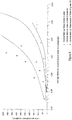
- the 38cm internal diameter column was equipped with a main sparger installed at a low level in the column.
- a secondary sparger was installed above the main sparger and was sometimes used for introducing re-suspension fluids into the column.
- the steady state flow rate of air to the column (i.e. the analogy of the reactor feed gas flow rate of a reactive system) was a superficial gas velocity of at least 10 cm/s inside the column in all experiments on both columns.
- the values of the uplift force spikes were normalized by dividing the values obtained experimentally in Example 2 by the mean uplift force value obtained when the start-up was performed using a gas only.
- Example 3 Start-up procedure involving first feeding re-suspension liquid, then a start-up gas at a low flow rate and then commencing the feed gas flow rate
- the glass beads were allowed to settle out from a fluidised state by shutting off the air flow to the column.
- the bed was re-fluidised by first introducing a re-suspension liquid flow to the column through the secondary sparger for a certain period of time.
- a start-up gas was introduced into the column through the secondary sparger at a low flow rate, i.e. a flow rate less than 10 cm/s.
- the normal feed gas flow (superficial gas velocity of 10 cm/s) was introduced through the main sparger. The maximum bed uplift force measured during the start-up procedure was recorded.
- Example 5 Correlation between results obtained with glass beads and with catalyst.
- the uplift forces generated using oxidised cobalt Fischer-Tropsch catalyst particles were compared with the uplift forces generated using a glass bead system for similar bed heights.
- the selected glass beads have a similar particle size distribution to the oxidised cobalt catalyst.
- the catalyst particles and glass beads were allowed to settle out from a fluidised state by shutting off the air flow to the column. After the bed had settled completely, i.e. all particles had settled out, the bed was re-fluidised by first introducing a re-suspension liquid flow to the column through the main distributor for a certain period of time. Immediately thereafter, a start-up gas was introduced into the column through the main distributor.
- the invention advantageously allows re-suspension of a settled or slumped catalyst bed in a slurry bubble column reactor vessel without introducing large uplift forces, e.g. uplift forces approaching 200kN/m 2 , to the reactor vessel and/or internals of the reactor vessel.
- the method of the invention can advantageously employ existing apparatus, such as a gas sparger, to introduce a flow of a re-suspension liquid to the settled or slumped bed, and/or employ a re-suspension liquid which can remain in the slurry bubble column reactor vessel as part of the liquid phase of the slurry bed after operation of the reactor vessel with a re-constituted slurry bed has commenced.
Landscapes
- Chemical & Material Sciences (AREA)
- Oil, Petroleum & Natural Gas (AREA)
- Engineering & Computer Science (AREA)
- Organic Chemistry (AREA)
- Chemical Kinetics & Catalysis (AREA)
- General Chemical & Material Sciences (AREA)
- Combustion & Propulsion (AREA)
- Devices And Processes Conducted In The Presence Of Fluids And Solid Particles (AREA)
- Control For Baths (AREA)
Claims (12)
- Verfahren zur Inbetriebnahme eines Suspensionsblasensäulenreaktors, der ein Reaktorbehälter beinhaltet, das ein festgesetztes oder abgesunkenes Bett aus Partikeln enthält, wobei die Partikel einen mittleren Partikeldurchmesser, bestimmt auf einer volumetrischen Basis von weniger als 200 Mikrometer, und eine flüssige Phase, aus der sich die Partikel abgesetzt haben, aufweisen, wobei das Verfahren umfasst
Einleiten eines Stroms einer Resuspensionsflüssigkeit in das festgesetzte oder abgesunkene Bett gleichmäßig über einen Querschnitt des Reaktorbehälters durch einen Verteiler oder Sparger auf einem niedrigen Level in dem Reaktor, um das festgesetzte oder abgesunkene Bett zu lösen, wobei das Einleiten der Resuspensionsflüssigkeit vor dem Einleiten von Gas in das festgesetzte oder abgesunkene Bett oder zusammen mit dem Einleiten von Gas in das festgesetzte oder abgesunkene Bett erfolgt, vorausgesetzt, dass, wenn Gas zusammen mit der Resuspensionsflüssigkeit in das festgesetzte oder abgesunkene Bett eingeleitet wird, bevor das festgesetzte oder abgesunkene Bett gelöst wurde, das Gas eine oberflächliche Gasgeschwindigkeit in dem Reaktor von unter 10 cm/s aufweist, wobei das Volumen der Resuspensionsflüssigkeit, das in das festgesetzte oder abgesunkene Bett vor dem Einleiten von Gas mit einer Oberflächengeschwindigkeit von über 10 cm/s eingeleitet wird, mindestens 5% eines Interpartikelvolumens des festgesetzten oder abgesunkenen Bettes beträgt, der Strom der Respensionsflüssigkeit mit einer oberflächlichen Flüssigkeitsgeschwindigkeit in den Reaktorbehälter eingeleitet wird, die größer ist als die minimale Fluidisierungsgeschwindigkeit der Partikel des festgesetzten oder abgesunkenen Bettes in der flüssigen Phase in dem Reaktorbehälter, und die Resuspensionsflüssigkeit eine Viskosität von weniger als 10 cP bei der Temperatur des festgesetzten oder abgesunkenen Bettes in dem Reaktorbehälter aufweist; wobei vor dem Einleiten des Stroms der Respensionsflüssigkeit sichergestellt wird, dass die flüssige Phase in dem Reaktorbehälter eine solche Temperatur aufweist, dass die flüssige Phase eine Viskosität von weniger als 10 cP aufweist;
und
sobald das festgesetzte oder abgesunkene Bett durch mindestens die Resuspensionsflüssigkeit gelöst wurde, Leiten von Gas mit einer oberflächlichen Gasgeschwindigkeit von über 10 cm/s durch die flüssige Phase. - Verfahren nach Anspruch 1, wobei der Suspensionsblasensäulenreaktor zur Fischer-Tropsch-Synthese verwendet wird und wobei die Partikel feste Fischer-Tropsch-Katalysatorpartikel enthalten.
- Verfahren nach Anspruch 1 oder 2, wobei die Resuspensionsflüssigkeit eine Viskosität von weniger als 4 cP bei der Temperatur des festgesetzten oder abgesunkenen Bettes in dem Reaktorbehälter aufweist.
- Verfahren nach einem der Ansprüche 1 bis 3, welches umfasst, vor dem Einleiten des Stroms der Resuspensionsflüssigkeit, Sicherstellen, dass die flüssige Phase in dem Reaktorbehälter eine solche Temperatur aufweist, dass die flüssige Phase eine Viskosität von weniger als 4 cP aufweist.
- Verfahren nach einem der Ansprüche 1 bis 4, wobei das Volumen der Resuspensionsflüssigkeit, das in das festgesetzte oder abgesunkene Bett vor dem Einleiten von Gas mit einer Oberflächengeschwindigkeit von über 10 cm/s eingeleitet wird, mindestens 15%, vorzugsweise mindestens 30%, des Interpartikelvolumens des festgesetzten oder abgesunkenen Bettes beträgt.
- Verfahren nach einem der Ansprüche 1 bis 5, wobei der Strom der Resuspensionsflüssigkeit, der in das festgesetzte oder abgesunkene Bett eingeleitet wird, eine oberflächliche Flüssigkeitsgeschwindigkeit in dem Reaktorbehälter aufweist, die größer ist als die minimale Fluidisierungsgeschwindigkeit der Partikel des festgesetzten oder abgesunkenen Bettes in der flüssigen Phase in dem Reaktorbehälter.
- Verfahren nach einem der Ansprüche 1 bis 6, welches umfasst, Einleiten des Stroms der Resuspensionsflüssigkeit in das festgesetzte oder abgesunkene Bett zum Lösen des festgesetzten oder abgesunkenen Bettes zusammen mit Einleiten von Gas in das festgesetzte oder abgesunkene Bett, wobei das Gas ein Anlaufgas mit einer oberflächlichen Gasgeschwindigkeit in dem Reaktor von unter 10 cm/s ist.
- Verfahren nach Anspruch 7, wobei das Anlaufgas eine oberflächliche Gasgeschwindigkeit in dem Reaktorbehälter aufweist, die nicht mehr als 5 cm/s beträgt.
- Verfahren nach Anspruch 7 oder 8, welches umfasst, graduelles Erhöhen der Flussrate des Anlaufgases zu einer oberflächlichen Gasgeschwindigkeit in dem Reaktorbehälter über 10 cm/s.
- Verfahren nach einem der Ansprüche 7 bis 9, wobei das Anlaufgas ein Inertgas ist.
- Verfahren nach einem der Ansprüche 7 bis 9, wobei das Anlaufgas gleich oder ähnlich einem Reaktoreinsatzgas ist, oder wobei das Anlaufgas ein an Wasserstoff reiches Gas ist, wobei das Verfahren ein Halten der Temperatur des Reaktorbehälters unterhalb einer Onset-Temperatur der Reaktion beim Lösen des festgesetzten oder abgesunkenen Bettes umfasst, um die Wärmeerzeugung oder -verbrauch aus der Reaktion zu hemmen oder zu vermeiden.
- Verfahren nach Anspruch 2, wobei der Strom der Resuspensionsflüssigkeit eingeleitet wird mit einer oberflächlichen Flüssigkeitsgeschwindigkeit in dem Reaktorbehälter von mindestens 0,4 mm/s, vorzugsweise mindestens 0,5 mm/s, besonders bevorzugt mindestens 0,8 mm/s.
Applications Claiming Priority (2)
| Application Number | Priority Date | Filing Date | Title |
|---|---|---|---|
| ZA201505974 | 2015-08-19 | ||
| PCT/IB2016/054806 WO2017029581A1 (en) | 2015-08-19 | 2016-08-10 | A method of operating a slurry bubble column reactor |
Publications (2)
| Publication Number | Publication Date |
|---|---|
| EP3337874A1 EP3337874A1 (de) | 2018-06-27 |
| EP3337874B1 true EP3337874B1 (de) | 2019-09-25 |
Family
ID=56852308
Family Applications (1)
| Application Number | Title | Priority Date | Filing Date |
|---|---|---|---|
| EP16759873.9A Active EP3337874B1 (de) | 2015-08-19 | 2016-08-10 | Verfahren zum betrieb eines suspensionsblasensäulenreaktors |
Country Status (8)
| Country | Link |
|---|---|
| US (1) | US11505749B2 (de) |
| EP (1) | EP3337874B1 (de) |
| CN (1) | CN108603123B (de) |
| BR (1) | BR112018003216B1 (de) |
| CA (1) | CA2995432C (de) |
| EA (1) | EA033413B1 (de) |
| WO (1) | WO2017029581A1 (de) |
| ZA (1) | ZA201801003B (de) |
Families Citing this family (1)
| Publication number | Priority date | Publication date | Assignee | Title |
|---|---|---|---|---|
| CN110591763B (zh) * | 2019-09-10 | 2021-01-15 | 南京延长反应技术研究院有限公司 | 一种煤间接液化的智能强化控制系统及工艺 |
Family Cites Families (10)
| Publication number | Priority date | Publication date | Assignee | Title |
|---|---|---|---|---|
| US2987465A (en) | 1958-06-20 | 1961-06-06 | Hydrocarbon Research Inc | Gas-liquid contacting process |
| US5492617A (en) * | 1989-07-19 | 1996-02-20 | Trimble; Harold J. | Apparatus and method for quenching in hydroprocessing of a hydrocarbon feed stream |
| AU774304B2 (en) * | 1999-10-14 | 2004-06-24 | Sasol Technology (Pty) Limited | Handling of a catalyst |
| US7230034B2 (en) * | 2004-03-19 | 2007-06-12 | Conocophillips Company | Prevention of and recovering from a catalyst bed slumping in a gas-agitated multiphase reactor |
| US9168501B2 (en) * | 2007-09-10 | 2015-10-27 | Res Usa, Llc | Commercial Fischer-Tropsch reactor |
| ITMI20080007A1 (it) * | 2008-01-04 | 2009-07-05 | Eni Spa | Procedimento per stabilizzare le prestazioni di un catalizzatore per la reazione di fischer tropsch |
| GB2465554B (en) * | 2008-11-18 | 2013-03-13 | Gtl F1 Ag | Slurry bubble column reactor |
| US8119014B2 (en) * | 2008-12-23 | 2012-02-21 | Exxonmobil Research And Engineering Company | Systems and methods to remove liquid product and fines from a slurry reactor |
| JP5887063B2 (ja) * | 2011-03-30 | 2016-03-16 | 独立行政法人石油天然ガス・金属鉱物資源機構 | 炭化水素合成反応装置及びそのスタートアップ方法、並びに炭化水素合成反応システム |
| JP5869397B2 (ja) * | 2012-03-28 | 2016-02-24 | 独立行政法人石油天然ガス・金属鉱物資源機構 | 気泡塔型スラリー床反応器のスタートアップ方法 |
-
2016
- 2016-08-10 WO PCT/IB2016/054806 patent/WO2017029581A1/en not_active Ceased
- 2016-08-10 CA CA2995432A patent/CA2995432C/en active Active
- 2016-08-10 EP EP16759873.9A patent/EP3337874B1/de active Active
- 2016-08-10 US US15/932,374 patent/US11505749B2/en active Active
- 2016-08-10 CN CN201680060602.3A patent/CN108603123B/zh active Active
- 2016-08-10 EA EA201890496A patent/EA033413B1/ru unknown
- 2016-08-10 BR BR112018003216-6A patent/BR112018003216B1/pt active IP Right Grant
-
2018
- 2018-02-14 ZA ZA2018/01003A patent/ZA201801003B/en unknown
Non-Patent Citations (1)
| Title |
|---|
| None * |
Also Published As
| Publication number | Publication date |
|---|---|
| CN108603123B (zh) | 2020-06-09 |
| US11505749B2 (en) | 2022-11-22 |
| EP3337874A1 (de) | 2018-06-27 |
| WO2017029581A1 (en) | 2017-02-23 |
| ZA201801003B (en) | 2018-12-19 |
| BR112018003216B1 (pt) | 2022-04-19 |
| CA2995432C (en) | 2023-01-24 |
| EA201890496A1 (ru) | 2018-07-31 |
| CN108603123A (zh) | 2018-09-28 |
| BR112018003216A2 (pt) | 2018-09-25 |
| EA033413B1 (ru) | 2019-10-31 |
| US20200283685A1 (en) | 2020-09-10 |
| CA2995432A1 (en) | 2017-02-23 |
Similar Documents
| Publication | Publication Date | Title |
|---|---|---|
| US10322393B2 (en) | Slurry phase apparatus | |
| DE69807691T2 (de) | Schlammkohlenwasserstoffsynthese mit externer produktfiltrierung | |
| CN102292416B (zh) | 从於浆反应器中取出液体产物和细粒的系统和方法 | |
| JP4203129B2 (ja) | ガス状反応物から液体生成物及び場合によりガス状生成物を製造する方法 | |
| US5589057A (en) | Method for extending the life of hydroprocessing catalyst | |
| WO2007069317A1 (ja) | 気泡塔型フィッシャー・トロプシュ合成スラリー床反応システム | |
| US6712982B2 (en) | Method of removing catalyst particles from wax | |
| CA2525007C (en) | Process for producing liquid and, optionally, gaseous products from gaseous reactants | |
| US11505749B2 (en) | Method of operating a slurry bubble column reactor | |
| EP2832825B1 (de) | Verfahren zum start eines aufschlämmungsbettreaktors mit einem blasenturm | |
| AU2010214107B2 (en) | Slurry reactor fines segregation and removal | |
| US9487710B2 (en) | Process for producing at least one product from at least one gaseous reactant in a slurry bed | |
| US9080108B2 (en) | Process for producing at least one product from at least one gaseous reactant in a slurry bed | |
| RU204762U1 (ru) | Устройство для проведения реакций в суспензионном слое наноразмерного катализатора | |
| JPH0572439B2 (de) | ||
| NO321115B1 (no) | Fremgangsmate og apparat for produksjon av hydrokarboner ved hjelp av Fisher-Tropsch-prosessen i en reaktor som omfatter midler for begrensning av faststoff-abbrasjon i resirkuleringssloyfen | |
| NZ618392B2 (en) | Process for producing at least one product from at least one gaseous reactant in a slurry bed | |
| NZ618388B2 (en) | Process for producing at least one product from at least one gaseous reactant in a slurry bed |
Legal Events
| Date | Code | Title | Description |
|---|---|---|---|
| STAA | Information on the status of an ep patent application or granted ep patent |
Free format text: STATUS: THE INTERNATIONAL PUBLICATION HAS BEEN MADE |
|
| PUAI | Public reference made under article 153(3) epc to a published international application that has entered the european phase |
Free format text: ORIGINAL CODE: 0009012 |
|
| STAA | Information on the status of an ep patent application or granted ep patent |
Free format text: STATUS: REQUEST FOR EXAMINATION WAS MADE |
|
| 17P | Request for examination filed |
Effective date: 20180208 |
|
| AK | Designated contracting states |
Kind code of ref document: A1 Designated state(s): AL AT BE BG CH CY CZ DE DK EE ES FI FR GB GR HR HU IE IS IT LI LT LU LV MC MK MT NL NO PL PT RO RS SE SI SK SM TR |
|
| AX | Request for extension of the european patent |
Extension state: BA ME |
|
| DAV | Request for validation of the european patent (deleted) | ||
| DAX | Request for extension of the european patent (deleted) | ||
| GRAP | Despatch of communication of intention to grant a patent |
Free format text: ORIGINAL CODE: EPIDOSNIGR1 |
|
| STAA | Information on the status of an ep patent application or granted ep patent |
Free format text: STATUS: GRANT OF PATENT IS INTENDED |
|
| INTG | Intention to grant announced |
Effective date: 20190320 |
|
| RAP1 | Party data changed (applicant data changed or rights of an application transferred) |
Owner name: SASOL TECHNOLOGY PROPRIETARY LIMITED |
|
| GRAS | Grant fee paid |
Free format text: ORIGINAL CODE: EPIDOSNIGR3 |
|
| GRAA | (expected) grant |
Free format text: ORIGINAL CODE: 0009210 |
|
| STAA | Information on the status of an ep patent application or granted ep patent |
Free format text: STATUS: THE PATENT HAS BEEN GRANTED |
|
| AK | Designated contracting states |
Kind code of ref document: B1 Designated state(s): AL AT BE BG CH CY CZ DE DK EE ES FI FR GB GR HR HU IE IS IT LI LT LU LV MC MK MT NL NO PL PT RO RS SE SI SK SM TR |
|
| REG | Reference to a national code |
Ref country code: GB Ref legal event code: FG4D |
|
| REG | Reference to a national code |
Ref country code: CH Ref legal event code: EP |
|
| REG | Reference to a national code |
Ref country code: AT Ref legal event code: REF Ref document number: 1183834 Country of ref document: AT Kind code of ref document: T Effective date: 20191015 |
|
| REG | Reference to a national code |
Ref country code: IE Ref legal event code: FG4D |
|
| REG | Reference to a national code |
Ref country code: DE Ref legal event code: R096 Ref document number: 602016021307 Country of ref document: DE |
|
| REG | Reference to a national code |
Ref country code: NL Ref legal event code: FP |
|
| PG25 | Lapsed in a contracting state [announced via postgrant information from national office to epo] |
Ref country code: LT Free format text: LAPSE BECAUSE OF FAILURE TO SUBMIT A TRANSLATION OF THE DESCRIPTION OR TO PAY THE FEE WITHIN THE PRESCRIBED TIME-LIMIT Effective date: 20190925 Ref country code: HR Free format text: LAPSE BECAUSE OF FAILURE TO SUBMIT A TRANSLATION OF THE DESCRIPTION OR TO PAY THE FEE WITHIN THE PRESCRIBED TIME-LIMIT Effective date: 20190925 Ref country code: FI Free format text: LAPSE BECAUSE OF FAILURE TO SUBMIT A TRANSLATION OF THE DESCRIPTION OR TO PAY THE FEE WITHIN THE PRESCRIBED TIME-LIMIT Effective date: 20190925 Ref country code: SE Free format text: LAPSE BECAUSE OF FAILURE TO SUBMIT A TRANSLATION OF THE DESCRIPTION OR TO PAY THE FEE WITHIN THE PRESCRIBED TIME-LIMIT Effective date: 20190925 Ref country code: BG Free format text: LAPSE BECAUSE OF FAILURE TO SUBMIT A TRANSLATION OF THE DESCRIPTION OR TO PAY THE FEE WITHIN THE PRESCRIBED TIME-LIMIT Effective date: 20191225 Ref country code: NO Free format text: LAPSE BECAUSE OF FAILURE TO SUBMIT A TRANSLATION OF THE DESCRIPTION OR TO PAY THE FEE WITHIN THE PRESCRIBED TIME-LIMIT Effective date: 20191225 |
|
| REG | Reference to a national code |
Ref country code: LT Ref legal event code: MG4D |
|
| PG25 | Lapsed in a contracting state [announced via postgrant information from national office to epo] |
Ref country code: LV Free format text: LAPSE BECAUSE OF FAILURE TO SUBMIT A TRANSLATION OF THE DESCRIPTION OR TO PAY THE FEE WITHIN THE PRESCRIBED TIME-LIMIT Effective date: 20190925 Ref country code: RS Free format text: LAPSE BECAUSE OF FAILURE TO SUBMIT A TRANSLATION OF THE DESCRIPTION OR TO PAY THE FEE WITHIN THE PRESCRIBED TIME-LIMIT Effective date: 20190925 Ref country code: GR Free format text: LAPSE BECAUSE OF FAILURE TO SUBMIT A TRANSLATION OF THE DESCRIPTION OR TO PAY THE FEE WITHIN THE PRESCRIBED TIME-LIMIT Effective date: 20191226 |
|
| REG | Reference to a national code |
Ref country code: AT Ref legal event code: MK05 Ref document number: 1183834 Country of ref document: AT Kind code of ref document: T Effective date: 20190925 |
|
| PG25 | Lapsed in a contracting state [announced via postgrant information from national office to epo] |
Ref country code: AT Free format text: LAPSE BECAUSE OF FAILURE TO SUBMIT A TRANSLATION OF THE DESCRIPTION OR TO PAY THE FEE WITHIN THE PRESCRIBED TIME-LIMIT Effective date: 20190925 Ref country code: RO Free format text: LAPSE BECAUSE OF FAILURE TO SUBMIT A TRANSLATION OF THE DESCRIPTION OR TO PAY THE FEE WITHIN THE PRESCRIBED TIME-LIMIT Effective date: 20190925 Ref country code: IT Free format text: LAPSE BECAUSE OF FAILURE TO SUBMIT A TRANSLATION OF THE DESCRIPTION OR TO PAY THE FEE WITHIN THE PRESCRIBED TIME-LIMIT Effective date: 20190925 Ref country code: PL Free format text: LAPSE BECAUSE OF FAILURE TO SUBMIT A TRANSLATION OF THE DESCRIPTION OR TO PAY THE FEE WITHIN THE PRESCRIBED TIME-LIMIT Effective date: 20190925 Ref country code: EE Free format text: LAPSE BECAUSE OF FAILURE TO SUBMIT A TRANSLATION OF THE DESCRIPTION OR TO PAY THE FEE WITHIN THE PRESCRIBED TIME-LIMIT Effective date: 20190925 Ref country code: ES Free format text: LAPSE BECAUSE OF FAILURE TO SUBMIT A TRANSLATION OF THE DESCRIPTION OR TO PAY THE FEE WITHIN THE PRESCRIBED TIME-LIMIT Effective date: 20190925 Ref country code: AL Free format text: LAPSE BECAUSE OF FAILURE TO SUBMIT A TRANSLATION OF THE DESCRIPTION OR TO PAY THE FEE WITHIN THE PRESCRIBED TIME-LIMIT Effective date: 20190925 Ref country code: PT Free format text: LAPSE BECAUSE OF FAILURE TO SUBMIT A TRANSLATION OF THE DESCRIPTION OR TO PAY THE FEE WITHIN THE PRESCRIBED TIME-LIMIT Effective date: 20200127 |
|
| PG25 | Lapsed in a contracting state [announced via postgrant information from national office to epo] |
Ref country code: SK Free format text: LAPSE BECAUSE OF FAILURE TO SUBMIT A TRANSLATION OF THE DESCRIPTION OR TO PAY THE FEE WITHIN THE PRESCRIBED TIME-LIMIT Effective date: 20190925 Ref country code: IS Free format text: LAPSE BECAUSE OF FAILURE TO SUBMIT A TRANSLATION OF THE DESCRIPTION OR TO PAY THE FEE WITHIN THE PRESCRIBED TIME-LIMIT Effective date: 20200224 Ref country code: SM Free format text: LAPSE BECAUSE OF FAILURE TO SUBMIT A TRANSLATION OF THE DESCRIPTION OR TO PAY THE FEE WITHIN THE PRESCRIBED TIME-LIMIT Effective date: 20190925 Ref country code: CZ Free format text: LAPSE BECAUSE OF FAILURE TO SUBMIT A TRANSLATION OF THE DESCRIPTION OR TO PAY THE FEE WITHIN THE PRESCRIBED TIME-LIMIT Effective date: 20190925 |
|
| REG | Reference to a national code |
Ref country code: DE Ref legal event code: R097 Ref document number: 602016021307 Country of ref document: DE |
|
| PG2D | Information on lapse in contracting state deleted |
Ref country code: IS |
|
| PG25 | Lapsed in a contracting state [announced via postgrant information from national office to epo] |
Ref country code: IS Free format text: LAPSE BECAUSE OF FAILURE TO SUBMIT A TRANSLATION OF THE DESCRIPTION OR TO PAY THE FEE WITHIN THE PRESCRIBED TIME-LIMIT Effective date: 20200126 Ref country code: DK Free format text: LAPSE BECAUSE OF FAILURE TO SUBMIT A TRANSLATION OF THE DESCRIPTION OR TO PAY THE FEE WITHIN THE PRESCRIBED TIME-LIMIT Effective date: 20190925 |
|
| PLBE | No opposition filed within time limit |
Free format text: ORIGINAL CODE: 0009261 |
|
| STAA | Information on the status of an ep patent application or granted ep patent |
Free format text: STATUS: NO OPPOSITION FILED WITHIN TIME LIMIT |
|
| 26N | No opposition filed |
Effective date: 20200626 |
|
| PG25 | Lapsed in a contracting state [announced via postgrant information from national office to epo] |
Ref country code: SI Free format text: LAPSE BECAUSE OF FAILURE TO SUBMIT A TRANSLATION OF THE DESCRIPTION OR TO PAY THE FEE WITHIN THE PRESCRIBED TIME-LIMIT Effective date: 20190925 |
|
| PG25 | Lapsed in a contracting state [announced via postgrant information from national office to epo] |
Ref country code: MC Free format text: LAPSE BECAUSE OF FAILURE TO SUBMIT A TRANSLATION OF THE DESCRIPTION OR TO PAY THE FEE WITHIN THE PRESCRIBED TIME-LIMIT Effective date: 20190925 |
|
| REG | Reference to a national code |
Ref country code: CH Ref legal event code: PL |
|
| GBPC | Gb: european patent ceased through non-payment of renewal fee |
Effective date: 20200810 |
|
| PG25 | Lapsed in a contracting state [announced via postgrant information from national office to epo] |
Ref country code: LI Free format text: LAPSE BECAUSE OF NON-PAYMENT OF DUE FEES Effective date: 20200831 Ref country code: LU Free format text: LAPSE BECAUSE OF NON-PAYMENT OF DUE FEES Effective date: 20200810 Ref country code: CH Free format text: LAPSE BECAUSE OF NON-PAYMENT OF DUE FEES Effective date: 20200831 |
|
| REG | Reference to a national code |
Ref country code: BE Ref legal event code: MM Effective date: 20200831 |
|
| PG25 | Lapsed in a contracting state [announced via postgrant information from national office to epo] |
Ref country code: FR Free format text: LAPSE BECAUSE OF NON-PAYMENT OF DUE FEES Effective date: 20200831 |
|
| PG25 | Lapsed in a contracting state [announced via postgrant information from national office to epo] |
Ref country code: BE Free format text: LAPSE BECAUSE OF NON-PAYMENT OF DUE FEES Effective date: 20200831 Ref country code: GB Free format text: LAPSE BECAUSE OF NON-PAYMENT OF DUE FEES Effective date: 20200810 Ref country code: IE Free format text: LAPSE BECAUSE OF NON-PAYMENT OF DUE FEES Effective date: 20200810 |
|
| PG25 | Lapsed in a contracting state [announced via postgrant information from national office to epo] |
Ref country code: TR Free format text: LAPSE BECAUSE OF FAILURE TO SUBMIT A TRANSLATION OF THE DESCRIPTION OR TO PAY THE FEE WITHIN THE PRESCRIBED TIME-LIMIT Effective date: 20190925 Ref country code: MT Free format text: LAPSE BECAUSE OF FAILURE TO SUBMIT A TRANSLATION OF THE DESCRIPTION OR TO PAY THE FEE WITHIN THE PRESCRIBED TIME-LIMIT Effective date: 20190925 Ref country code: CY Free format text: LAPSE BECAUSE OF FAILURE TO SUBMIT A TRANSLATION OF THE DESCRIPTION OR TO PAY THE FEE WITHIN THE PRESCRIBED TIME-LIMIT Effective date: 20190925 |
|
| PG25 | Lapsed in a contracting state [announced via postgrant information from national office to epo] |
Ref country code: MK Free format text: LAPSE BECAUSE OF FAILURE TO SUBMIT A TRANSLATION OF THE DESCRIPTION OR TO PAY THE FEE WITHIN THE PRESCRIBED TIME-LIMIT Effective date: 20190925 |
|
| P01 | Opt-out of the competence of the unified patent court (upc) registered |
Effective date: 20230502 |
|
| PGFP | Annual fee paid to national office [announced via postgrant information from national office to epo] |
Ref country code: NL Payment date: 20250821 Year of fee payment: 10 |
|
| PGFP | Annual fee paid to national office [announced via postgrant information from national office to epo] |
Ref country code: DE Payment date: 20250820 Year of fee payment: 10 |