EP3336670A1 - Touch sensor and display device including the same - Google Patents
Touch sensor and display device including the same Download PDFInfo
- Publication number
- EP3336670A1 EP3336670A1 EP17205715.0A EP17205715A EP3336670A1 EP 3336670 A1 EP3336670 A1 EP 3336670A1 EP 17205715 A EP17205715 A EP 17205715A EP 3336670 A1 EP3336670 A1 EP 3336670A1
- Authority
- EP
- European Patent Office
- Prior art keywords
- touch
- sensing cells
- connection patterns
- connection
- touch sensor
- Prior art date
- Legal status (The legal status is an assumption and is not a legal conclusion. Google has not performed a legal analysis and makes no representation as to the accuracy of the status listed.)
- Granted
Links
- 239000000758 substrate Substances 0.000 claims abstract description 45
- 239000012212 insulator Substances 0.000 claims description 78
- 239000010410 layer Substances 0.000 claims description 36
- 239000000463 material Substances 0.000 claims description 18
- 230000003247 decreasing effect Effects 0.000 claims description 15
- 230000008859 change Effects 0.000 claims description 13
- -1 polydimethylsiloxane Polymers 0.000 claims description 11
- 239000004205 dimethyl polysiloxane Substances 0.000 claims description 7
- 229920000435 poly(dimethylsiloxane) Polymers 0.000 claims description 7
- 239000002356 single layer Substances 0.000 claims description 5
- 239000013013 elastic material Substances 0.000 claims description 4
- 239000004020 conductor Substances 0.000 description 8
- 230000035945 sensitivity Effects 0.000 description 6
- 239000000615 nonconductor Substances 0.000 description 5
- 230000015572 biosynthetic process Effects 0.000 description 4
- 229910052751 metal Inorganic materials 0.000 description 4
- 239000002184 metal Substances 0.000 description 4
- PXHVJJICTQNCMI-UHFFFAOYSA-N Nickel Chemical compound [Ni] PXHVJJICTQNCMI-UHFFFAOYSA-N 0.000 description 3
- 229910003460 diamond Inorganic materials 0.000 description 3
- 239000010432 diamond Substances 0.000 description 3
- BASFCYQUMIYNBI-UHFFFAOYSA-N platinum Chemical compound [Pt] BASFCYQUMIYNBI-UHFFFAOYSA-N 0.000 description 3
- 239000011347 resin Substances 0.000 description 3
- 229920005989 resin Polymers 0.000 description 3
- XOLBLPGZBRYERU-UHFFFAOYSA-N tin dioxide Chemical compound O=[Sn]=O XOLBLPGZBRYERU-UHFFFAOYSA-N 0.000 description 3
- OKTJSMMVPCPJKN-UHFFFAOYSA-N Carbon Chemical compound [C] OKTJSMMVPCPJKN-UHFFFAOYSA-N 0.000 description 2
- 239000004793 Polystyrene Substances 0.000 description 2
- BQCADISMDOOEFD-UHFFFAOYSA-N Silver Chemical compound [Ag] BQCADISMDOOEFD-UHFFFAOYSA-N 0.000 description 2
- 239000011651 chromium Substances 0.000 description 2
- 239000010949 copper Substances 0.000 description 2
- 239000011152 fibreglass Substances 0.000 description 2
- 239000011521 glass Substances 0.000 description 2
- 239000010931 gold Substances 0.000 description 2
- 238000000034 method Methods 0.000 description 2
- 238000012986 modification Methods 0.000 description 2
- 230000004048 modification Effects 0.000 description 2
- 229920000139 polyethylene terephthalate Polymers 0.000 description 2
- 239000005020 polyethylene terephthalate Substances 0.000 description 2
- 229920002223 polystyrene Polymers 0.000 description 2
- 239000010936 titanium Substances 0.000 description 2
- 229920008347 Cellulose acetate propionate Polymers 0.000 description 1
- VYZAMTAEIAYCRO-UHFFFAOYSA-N Chromium Chemical compound [Cr] VYZAMTAEIAYCRO-UHFFFAOYSA-N 0.000 description 1
- RYGMFSIKBFXOCR-UHFFFAOYSA-N Copper Chemical compound [Cu] RYGMFSIKBFXOCR-UHFFFAOYSA-N 0.000 description 1
- 239000004593 Epoxy Substances 0.000 description 1
- ZOKXTWBITQBERF-UHFFFAOYSA-N Molybdenum Chemical compound [Mo] ZOKXTWBITQBERF-UHFFFAOYSA-N 0.000 description 1
- 229910052779 Neodymium Inorganic materials 0.000 description 1
- 239000004695 Polyether sulfone Substances 0.000 description 1
- 239000004697 Polyetherimide Substances 0.000 description 1
- 239000004642 Polyimide Substances 0.000 description 1
- 239000004734 Polyphenylene sulfide Substances 0.000 description 1
- 239000004372 Polyvinyl alcohol Substances 0.000 description 1
- 239000002042 Silver nanowire Substances 0.000 description 1
- RTAQQCXQSZGOHL-UHFFFAOYSA-N Titanium Chemical compound [Ti] RTAQQCXQSZGOHL-UHFFFAOYSA-N 0.000 description 1
- XLOMVQKBTHCTTD-UHFFFAOYSA-N Zinc monoxide Chemical compound [Zn]=O XLOMVQKBTHCTTD-UHFFFAOYSA-N 0.000 description 1
- 239000000956 alloy Substances 0.000 description 1
- 229910045601 alloy Inorganic materials 0.000 description 1
- 229910052782 aluminium Inorganic materials 0.000 description 1
- XAGFODPZIPBFFR-UHFFFAOYSA-N aluminium Chemical compound [Al] XAGFODPZIPBFFR-UHFFFAOYSA-N 0.000 description 1
- 239000002041 carbon nanotube Substances 0.000 description 1
- 229910021393 carbon nanotube Inorganic materials 0.000 description 1
- 239000001913 cellulose Substances 0.000 description 1
- 229920006218 cellulose propionate Polymers 0.000 description 1
- 229910052804 chromium Inorganic materials 0.000 description 1
- 229910052802 copper Inorganic materials 0.000 description 1
- 238000010168 coupling process Methods 0.000 description 1
- 238000011161 development Methods 0.000 description 1
- 230000018109 developmental process Effects 0.000 description 1
- 238000010586 diagram Methods 0.000 description 1
- PCHJSUWPFVWCPO-UHFFFAOYSA-N gold Chemical compound [Au] PCHJSUWPFVWCPO-UHFFFAOYSA-N 0.000 description 1
- 229910052737 gold Inorganic materials 0.000 description 1
- 229910021389 graphene Inorganic materials 0.000 description 1
- AMGQUBHHOARCQH-UHFFFAOYSA-N indium;oxotin Chemical compound [In].[Sn]=O AMGQUBHHOARCQH-UHFFFAOYSA-N 0.000 description 1
- 238000004519 manufacturing process Methods 0.000 description 1
- 239000011159 matrix material Substances 0.000 description 1
- 229910052750 molybdenum Inorganic materials 0.000 description 1
- 239000011733 molybdenum Substances 0.000 description 1
- QEFYFXOXNSNQGX-UHFFFAOYSA-N neodymium atom Chemical compound [Nd] QEFYFXOXNSNQGX-UHFFFAOYSA-N 0.000 description 1
- 229910052759 nickel Inorganic materials 0.000 description 1
- 239000004033 plastic Substances 0.000 description 1
- 229920003023 plastic Polymers 0.000 description 1
- 229910052697 platinum Inorganic materials 0.000 description 1
- 229920003207 poly(ethylene-2,6-naphthalate) Polymers 0.000 description 1
- 229920003229 poly(methyl methacrylate) Polymers 0.000 description 1
- 229920000058 polyacrylate Polymers 0.000 description 1
- 229920002647 polyamide Polymers 0.000 description 1
- 229920001230 polyarylate Polymers 0.000 description 1
- 239000004417 polycarbonate Substances 0.000 description 1
- 229920000515 polycarbonate Polymers 0.000 description 1
- 229920000728 polyester Polymers 0.000 description 1
- 229920006393 polyether sulfone Polymers 0.000 description 1
- 229920001601 polyetherimide Polymers 0.000 description 1
- 239000011112 polyethylene naphthalate Substances 0.000 description 1
- 229920001721 polyimide Polymers 0.000 description 1
- 239000004926 polymethyl methacrylate Substances 0.000 description 1
- 229920000098 polyolefin Polymers 0.000 description 1
- 229920000069 polyphenylene sulfide Polymers 0.000 description 1
- 229920002635 polyurethane Polymers 0.000 description 1
- 239000004814 polyurethane Substances 0.000 description 1
- 229920002451 polyvinyl alcohol Polymers 0.000 description 1
- 230000008569 process Effects 0.000 description 1
- 230000004044 response Effects 0.000 description 1
- 229910052710 silicon Inorganic materials 0.000 description 1
- 239000010703 silicon Substances 0.000 description 1
- 229910052709 silver Inorganic materials 0.000 description 1
- 239000004332 silver Substances 0.000 description 1
- 238000004088 simulation Methods 0.000 description 1
- 229910001887 tin oxide Inorganic materials 0.000 description 1
- 229910052719 titanium Inorganic materials 0.000 description 1
- ILJSQTXMGCGYMG-UHFFFAOYSA-N triacetic acid Chemical compound CC(=O)CC(=O)CC(O)=O ILJSQTXMGCGYMG-UHFFFAOYSA-N 0.000 description 1
- OWOMRZKBDFBMHP-UHFFFAOYSA-N zinc antimony(3+) oxygen(2-) Chemical compound [O--].[Zn++].[Sb+3] OWOMRZKBDFBMHP-UHFFFAOYSA-N 0.000 description 1
- YVTHLONGBIQYBO-UHFFFAOYSA-N zinc indium(3+) oxygen(2-) Chemical compound [O--].[Zn++].[In+3] YVTHLONGBIQYBO-UHFFFAOYSA-N 0.000 description 1
- TYHJXGDMRRJCRY-UHFFFAOYSA-N zinc indium(3+) oxygen(2-) tin(4+) Chemical compound [O-2].[Zn+2].[Sn+4].[In+3] TYHJXGDMRRJCRY-UHFFFAOYSA-N 0.000 description 1
Images


Classifications
-
- G—PHYSICS
- G06—COMPUTING; CALCULATING OR COUNTING
- G06F—ELECTRIC DIGITAL DATA PROCESSING
- G06F3/00—Input arrangements for transferring data to be processed into a form capable of being handled by the computer; Output arrangements for transferring data from processing unit to output unit, e.g. interface arrangements
- G06F3/01—Input arrangements or combined input and output arrangements for interaction between user and computer
- G06F3/03—Arrangements for converting the position or the displacement of a member into a coded form
- G06F3/041—Digitisers, e.g. for touch screens or touch pads, characterised by the transducing means
- G06F3/0414—Digitisers, e.g. for touch screens or touch pads, characterised by the transducing means using force sensing means to determine a position
-
- G—PHYSICS
- G06—COMPUTING; CALCULATING OR COUNTING
- G06F—ELECTRIC DIGITAL DATA PROCESSING
- G06F3/00—Input arrangements for transferring data to be processed into a form capable of being handled by the computer; Output arrangements for transferring data from processing unit to output unit, e.g. interface arrangements
- G06F3/01—Input arrangements or combined input and output arrangements for interaction between user and computer
- G06F3/03—Arrangements for converting the position or the displacement of a member into a coded form
- G06F3/041—Digitisers, e.g. for touch screens or touch pads, characterised by the transducing means
- G06F3/0416—Control or interface arrangements specially adapted for digitisers
- G06F3/04164—Connections between sensors and controllers, e.g. routing lines between electrodes and connection pads
-
- G—PHYSICS
- G06—COMPUTING; CALCULATING OR COUNTING
- G06F—ELECTRIC DIGITAL DATA PROCESSING
- G06F3/00—Input arrangements for transferring data to be processed into a form capable of being handled by the computer; Output arrangements for transferring data from processing unit to output unit, e.g. interface arrangements
- G06F3/01—Input arrangements or combined input and output arrangements for interaction between user and computer
- G06F3/03—Arrangements for converting the position or the displacement of a member into a coded form
- G06F3/041—Digitisers, e.g. for touch screens or touch pads, characterised by the transducing means
- G06F3/0414—Digitisers, e.g. for touch screens or touch pads, characterised by the transducing means using force sensing means to determine a position
- G06F3/04144—Digitisers, e.g. for touch screens or touch pads, characterised by the transducing means using force sensing means to determine a position using an array of force sensing means
-
- G—PHYSICS
- G06—COMPUTING; CALCULATING OR COUNTING
- G06F—ELECTRIC DIGITAL DATA PROCESSING
- G06F3/00—Input arrangements for transferring data to be processed into a form capable of being handled by the computer; Output arrangements for transferring data from processing unit to output unit, e.g. interface arrangements
- G06F3/01—Input arrangements or combined input and output arrangements for interaction between user and computer
- G06F3/03—Arrangements for converting the position or the displacement of a member into a coded form
- G06F3/041—Digitisers, e.g. for touch screens or touch pads, characterised by the transducing means
- G06F3/0412—Digitisers structurally integrated in a display
-
- G—PHYSICS
- G06—COMPUTING; CALCULATING OR COUNTING
- G06F—ELECTRIC DIGITAL DATA PROCESSING
- G06F3/00—Input arrangements for transferring data to be processed into a form capable of being handled by the computer; Output arrangements for transferring data from processing unit to output unit, e.g. interface arrangements
- G06F3/01—Input arrangements or combined input and output arrangements for interaction between user and computer
- G06F3/03—Arrangements for converting the position or the displacement of a member into a coded form
- G06F3/041—Digitisers, e.g. for touch screens or touch pads, characterised by the transducing means
- G06F3/0416—Control or interface arrangements specially adapted for digitisers
-
- G—PHYSICS
- G06—COMPUTING; CALCULATING OR COUNTING
- G06F—ELECTRIC DIGITAL DATA PROCESSING
- G06F3/00—Input arrangements for transferring data to be processed into a form capable of being handled by the computer; Output arrangements for transferring data from processing unit to output unit, e.g. interface arrangements
- G06F3/01—Input arrangements or combined input and output arrangements for interaction between user and computer
- G06F3/03—Arrangements for converting the position or the displacement of a member into a coded form
- G06F3/041—Digitisers, e.g. for touch screens or touch pads, characterised by the transducing means
- G06F3/044—Digitisers, e.g. for touch screens or touch pads, characterised by the transducing means by capacitive means
- G06F3/0443—Digitisers, e.g. for touch screens or touch pads, characterised by the transducing means by capacitive means using a single layer of sensing electrodes
-
- G—PHYSICS
- G06—COMPUTING; CALCULATING OR COUNTING
- G06F—ELECTRIC DIGITAL DATA PROCESSING
- G06F3/00—Input arrangements for transferring data to be processed into a form capable of being handled by the computer; Output arrangements for transferring data from processing unit to output unit, e.g. interface arrangements
- G06F3/01—Input arrangements or combined input and output arrangements for interaction between user and computer
- G06F3/03—Arrangements for converting the position or the displacement of a member into a coded form
- G06F3/041—Digitisers, e.g. for touch screens or touch pads, characterised by the transducing means
- G06F3/044—Digitisers, e.g. for touch screens or touch pads, characterised by the transducing means by capacitive means
- G06F3/0445—Digitisers, e.g. for touch screens or touch pads, characterised by the transducing means by capacitive means using two or more layers of sensing electrodes, e.g. using two layers of electrodes separated by a dielectric layer
-
- G—PHYSICS
- G06—COMPUTING; CALCULATING OR COUNTING
- G06F—ELECTRIC DIGITAL DATA PROCESSING
- G06F3/00—Input arrangements for transferring data to be processed into a form capable of being handled by the computer; Output arrangements for transferring data from processing unit to output unit, e.g. interface arrangements
- G06F3/01—Input arrangements or combined input and output arrangements for interaction between user and computer
- G06F3/03—Arrangements for converting the position or the displacement of a member into a coded form
- G06F3/041—Digitisers, e.g. for touch screens or touch pads, characterised by the transducing means
- G06F3/044—Digitisers, e.g. for touch screens or touch pads, characterised by the transducing means by capacitive means
- G06F3/0446—Digitisers, e.g. for touch screens or touch pads, characterised by the transducing means by capacitive means using a grid-like structure of electrodes in at least two directions, e.g. using row and column electrodes
-
- G—PHYSICS
- G06—COMPUTING; CALCULATING OR COUNTING
- G06F—ELECTRIC DIGITAL DATA PROCESSING
- G06F3/00—Input arrangements for transferring data to be processed into a form capable of being handled by the computer; Output arrangements for transferring data from processing unit to output unit, e.g. interface arrangements
- G06F3/01—Input arrangements or combined input and output arrangements for interaction between user and computer
- G06F3/03—Arrangements for converting the position or the displacement of a member into a coded form
- G06F3/041—Digitisers, e.g. for touch screens or touch pads, characterised by the transducing means
- G06F3/044—Digitisers, e.g. for touch screens or touch pads, characterised by the transducing means by capacitive means
- G06F3/0447—Position sensing using the local deformation of sensor cells
-
- G—PHYSICS
- G06—COMPUTING; CALCULATING OR COUNTING
- G06F—ELECTRIC DIGITAL DATA PROCESSING
- G06F3/00—Input arrangements for transferring data to be processed into a form capable of being handled by the computer; Output arrangements for transferring data from processing unit to output unit, e.g. interface arrangements
- G06F3/01—Input arrangements or combined input and output arrangements for interaction between user and computer
- G06F3/03—Arrangements for converting the position or the displacement of a member into a coded form
- G06F3/041—Digitisers, e.g. for touch screens or touch pads, characterised by the transducing means
- G06F3/044—Digitisers, e.g. for touch screens or touch pads, characterised by the transducing means by capacitive means
- G06F3/0448—Details of the electrode shape, e.g. for enhancing the detection of touches, for generating specific electric field shapes, for enhancing display quality
-
- G—PHYSICS
- G06—COMPUTING; CALCULATING OR COUNTING
- G06F—ELECTRIC DIGITAL DATA PROCESSING
- G06F2203/00—Indexing scheme relating to G06F3/00 - G06F3/048
- G06F2203/041—Indexing scheme relating to G06F3/041 - G06F3/045
- G06F2203/04102—Flexible digitiser, i.e. constructional details for allowing the whole digitising part of a device to be flexed or rolled like a sheet of paper
-
- G—PHYSICS
- G06—COMPUTING; CALCULATING OR COUNTING
- G06F—ELECTRIC DIGITAL DATA PROCESSING
- G06F2203/00—Indexing scheme relating to G06F3/00 - G06F3/048
- G06F2203/041—Indexing scheme relating to G06F3/041 - G06F3/045
- G06F2203/04103—Manufacturing, i.e. details related to manufacturing processes specially suited for touch sensitive devices
-
- G—PHYSICS
- G06—COMPUTING; CALCULATING OR COUNTING
- G06F—ELECTRIC DIGITAL DATA PROCESSING
- G06F2203/00—Indexing scheme relating to G06F3/00 - G06F3/048
- G06F2203/041—Indexing scheme relating to G06F3/041 - G06F3/045
- G06F2203/04111—Cross over in capacitive digitiser, i.e. details of structures for connecting electrodes of the sensing pattern where the connections cross each other, e.g. bridge structures comprising an insulating layer, or vias through substrate
Abstract
Description
- Exemplary embodiments relate to a touch sensor and a display device including the same.
- As interest in information displays and demand for portable information media increase, research and commercialization has been directed toward display devices.
- Recent developments in display devices include touch sensors for receiving touch inputs of users, in addition to image display functions. Accordingly, users can more conveniently use the display devices through the touch sensors.
- Recently, various functions have been provided to users, using the pressures generated due to touches to provide information, as well as the touch positions.
- The above information disclosed in this Background section is only for enhancement of understanding of the background of the inventive concept, and, therefore, it may contain information that does not form the prior art that is already known in this country to a person of ordinary skill in the art.
- Exemplary embodiments provide a touch sensor capable of recognizing a touch pressure and a display device including the touch sensor.
- Additional aspects will be set forth in the detailed description which follows, and, in part, will be apparent from the disclosure, or may be learned by practice of the inventive concept.
- An exemplary embodiment of the present invention discloses a touch sensor including: a substrate; a plurality of first touch electrodes located on the substrate, the plurality of first touch electrodes each including first sensing cells and first connection patterns connected between the first sensing cells; a plurality of second touch electrodes located on the substrate while intersecting the first touch electrodes, the plurality of second touch electrodes each including second sensing cells and second connection patterns connected between the second sensing cells; and an insulating member located between the first connection patterns and the second connection patterns, the insulating member having elasticity, wherein a modulus of elasticity of the substrate is equal to or greater than that of the insulating member.
- The first connection patterns and the second connection patterns may intersect each other.
- The insulating member may include a plurality of insulators located between the first connection patterns and the second connection patterns, which intersect each other, the plurality of insulators being separated from one another.
- The first sensing cells and the second sensing cells may be located in the same layer.
- The insulating member may be formed in a single layer located between the first connection patterns and the second connection patterns.
- The insulating member may be located between the first touch electrodes and the second touch electrodes.
- The first sensing cells and the second sensing cells may be located in different layers.
- Each of the first connection patterns may include a first connection part connected between adjacent first sensing cells and at least one first protruding part protruding from the first connection part.
- The first protruding part may overlap with an adjacent second connection pattern.
- Each of the second connection patterns may include a second connection part connected between adjacent second sensing cells and at least one second protruding part protruding from the second connection part.
- The second protruding part may overlap with an adjacent first connection pattern.
- A concave groove corresponding to the second protruding part may be formed in at least one first sensing cell adjacent to the second protruding part.
- The first connection patterns may be located above the insulators. The second connection patterns may be located under the insulators.
- The first connection patterns may connect the first sensing cells through contact holes formed in the insulators.
- The first connection patterns may be located under the insulators. The second connection patterns may be located above the insulators.
- The first connection patterns may connect the first sensing cells through contact holes formed in the insulators.
- The touch sensor may further include an additional insulating layer located between the first touch electrodes and the second touch electrodes.
- The first sensing cells and the second sensing cells may be located in different layers.
- The touch sensor may further include a touch controller supplying a driving signal to the first touch electrodes, the touch controller recognizing a touch using output signals of the second touch electrodes.
- The touch controller may detect at least one of a position of the touch and a pressure of the touch through a change in capacitance calculated from the output signals.
- The touch controller may detect the position of the touch by recognizing a decrement of the capacitance.
- The touch controller may detect the pressure of the touch by recognizing an increment of the capacitance.
- The touch controller may calculate a level of the pressure through the increment of the capacitance.
- A distance between the first connection pattern and the second connection pattern, to which the pressure of the touch is applied, may be decreased.
- The substrate may have flexibility.
- The insulating member may include polydimethylsiloxane.
- The substrate may be formed of the same material as the insulating member.
- According to an aspect of the present disclosure, there is provided a display device including the above-described touch sensor.
- According to an aspect of the invention, there is provided a touch sensor as set out in
claim 1. Preferred features are set out in claims 2 to 14. - According to an aspect of the invention, there is provided a display device as set out in
claim 15. - The foregoing general description and the following detailed description are exemplary and explanatory and are intended to provide further explanation of the claimed subject matter.
- The accompanying drawings, which are included to provide a further understanding of the inventive concept, and are incorporated in and constitute a part of this specification, illustrate exemplary embodiments of the inventive concept, and, together with the description, serve to explain principles of the inventive concept.
-
FIG. 1 is a view illustrating a touch sensor according to an exemplary embodiment of the present disclosure. -
FIG. 2 is an enlarged view of some of the touch electrodes shown inFIG. 1 . -
FIG. 3 is a view illustrating a section taken along line I-I' ofFIG. 2 . -
FIG. 4A and FIG. 4B are views illustrating an operation of detecting a touch position according to an exemplary embodiment of the present disclosure. -
FIG. 5A, FIG. 5B , andFIG. 5C are views illustrating an operation of detecting a touch pressure according to an exemplary embodiment of the present disclosure. -
FIG. 6A, FIG. 6B, and FIG. 6C are views illustrating sections of touch electrodes according to an exemplary embodiment of the present disclosure. -
FIG. 7 is a view illustrating some touch electrodes according to an exemplary embodiment of the present disclosure. -
FIG. 8A is a view illustrating a section taken along line II-II' ofFIG. 7 . -
FIG. 8B is a view illustrating a section taken along line III-III' ofFIG. 7 . -
FIG. 9 is a view illustrating some touch electrodes according to an exemplary embodiment of the present disclosure. -
FIG. 10A is a view illustrating a section taken along line IV-IV' ofFIG. 9, and FIG. 10B is a view illustrating a section taken along line V-V' ofFIG. 9 . -
FIG. 11A, FIG. 11B, FIG. 11C, FIG. 11D, FIG. 11E, and FIG. 11F are views illustrating various exemplary embodiments of an insulator. -
FIG. 12A and FIG. 12B are views illustrating various exemplary embodiments of a second connection pattern. -
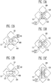
FIG. 13A, FIG. 13B, and FIG. 13C are views illustrating various exemplary embodiments of a first connection pattern. -
FIG. 14 is a view illustrating another exemplary embodiment of a sensing cell. -
FIG. 15 is a view illustrating a touch controller according to an exemplary embodiment of the present disclosure. -
FIG. 16A andFIG. 16B are views illustrating an operation of the touch controller according to an exemplary embodiment of the present disclosure. -
FIG. 17A and FIG. 17B are views illustrating shapes of the insulator according to an exemplary embodiment of the present disclosure. -
FIG. 18 is a view illustrating a display device according to an exemplary embodiment of the present disclosure. - In the following description, for the purposes of explanation, numerous specific details are set forth in order to provide a thorough understanding of various exemplary embodiments. It is apparent, however, that various exemplary embodiments may be practiced without these specific details or with one or more equivalent arrangements. In other instances, well-known structures and devices are shown in block diagram form in order to avoid unnecessarily obscuring various exemplary embodiments.
- In the accompanying figures, the size and relative sizes of layers, films, panels, regions, etc., may be exaggerated for clarity and descriptive purposes. Also, like reference numerals denote like elements.
- When an element or layer is referred to as being "on," "connected to," or "coupled to" another element or layer, it may be directly on, connected to, or coupled to the other element or layer or intervening elements or layers may be present. When, however, an element or layer is referred to as being "directly on," "directly connected to," or "directly coupled to" another element or layer, there are no intervening elements or layers present. For the purposes of this disclosure, "at least one of X, Y, and Z" and "at least one selected from the group consisting of X, Y, and Z" may be construed as X only, Y only, Z only, or any combination of two or more of X, Y, and Z, such as, for instance, XYZ, XYY, YZ, and ZZ. Like numbers refer to like elements throughout. As used herein, the term "and/or" includes any and all combinations of one or more of the associated listed items.
- Although the terms first, second, etc. may be used herein to describe various elements, components, regions, layers, and/or sections, these elements, components, regions, layers, and/or sections should not be limited by these terms. These terms are used to distinguish one element, component, region, layer, and/or section from another element, component, region, layer, and/or section. Thus, a first element, component, region, layer, and/or section discussed below could be termed a second element, component, region, layer, and/or section without departing from the teachings of the present disclosure.
- Spatially relative terms, such as "beneath," "below," "lower," "above," "upper," and the like, may be used herein for descriptive purposes, and, thereby, to describe one element or feature's relationship to another element(s) or feature(s) as illustrated in the drawings. Spatially relative terms are intended to encompass different orientations of an apparatus in use, operation, and/or manufacture in addition to the orientation depicted in the drawings. For example, if the apparatus in the drawings is turned over, elements described as "below" or "beneath" other elements or features would then be oriented "above" the other elements or features. Thus, the exemplary term "below" can encompass both an orientation of above and below. Furthermore, the apparatus may be otherwise oriented (e.g., rotated 90 degrees or at other orientations), and, as such, the spatially relative descriptors used herein interpreted accordingly.
- The terminology used herein is for the purpose of describing particular embodiments and is not intended to be limiting. As used herein, the singular forms, "a," "an," and "the" are intended to include the plural forms as well, unless the context clearly indicates otherwise. Moreover, the terms "comprises," "comprising," "includes," and/or "including," when used in this specification, specify the presence of stated features, integers, steps, operations, elements, components, and/or groups thereof, but do not preclude the presence or addition of one or more other features, integers, steps, operations, elements, components, and/or groups thereof.
-
FIG. 1 is a view illustrating a touch sensor according to an exemplary embodiment of the present disclosure. - Referring to
FIG. 1 , thetouch sensor 10 according to the exemplary embodiment of the present disclosure may include asubstrate 100,first touch electrodes 110,second touch electrodes 120, and atouch controller 150. - The
first touch electrodes 110 and thesecond touch electrodes 120 may be located on thesubstrate 100. - The
first touch electrodes 110 are formed to extend in a first direction (e.g., an X-axis direction), and may be arranged in plural numbers along a second direction (e.g., a Y-axis direction) intersecting the first direction. - The
second touch electrodes 120 are formed to extend in the second direction (e.g., the Y-axis direction), and may be arranged in plural numbers along the first direction (e.g., a Y-axis direction). - As a result of the
first touch electrodes 110 and thesecond touch electrodes 120 intersecting each other, thefirst touch electrodes 110 and thesecond touch electrodes 120 may be operated as a capacitive type touch sensor. - That is, mutual capacitances exist at intersection portions of the
first touch electrodes 110 and thesecond touch electrodes 120 and, when a touch is generated in thetouch sensor 10, a mutual capacitance at a position related to the touch is changed. A touch position may be detected by detecting a change in capacitance. - Each of the
first touch electrodes 110 may include a plurality offirst sensing cells 111 arranged at a predetermined distance along the first direction (e.g., the X-axis direction), and a plurality offirst connection patterns 112 electrically connecting thefirst sensing cells 111 to each other. In other words, thefirst touch electrodes 110 may each include a plurality offirst sensing cells 111 that are arranged in a formation that extends in the first direction, with adjacentfirst sensing cells 111 being electrically connected by afirst connection pattern 112. - In addition, each of the
second touch electrodes 120 may include a plurality ofsecond sensing cells 121 arranged at a predetermined distance along the second direction (e.g., the Y-axis direction), and a plurality ofsecond connection patterns 122 electrically connecting thesecond sensing cells 121 to each other. In other words, thesecond touch electrodes 120 may each include a plurality ofsecond sensing cells 121 that are arranged in a formation that extends in the second direction, with adjacentsecond sensing cells 121 being electrically connected by asecond connection pattern 122. - In this case, the second sensing cells may be dispersed and arranged between the
first sensing cells 111 so as not to overlap with thefirst sensing cells 111. In other words, the first andsecond touch electrodes 110 120 intersect, but the first andsecond sensing cells - In addition, the
first connection patterns 112 and thesecond connection patterns 122 may intersect each other. - Although a case where the
first sensing cells 111 and thesecond sensing cells 121 have a polygonal shape (e.g., a diamond shape) is illustrated inFIG. 1 , the shape of thefirst sensing cells 111 and thesecond sensing cells 121 is not limited thereto in embodiments of the invention, and may be modified in various ways. - The
first touch electrodes 110 and thesecond touch electrodes 120 may include a conductive material. For example, thefirst touch electrodes 110 and thesecond touch electrodes 120 may include a metal or an alloy containing metal. The metal may be gold (Au), silver (Ag), aluminum (Al), molybdenum (Mo), chromium (Cr), titanium (Ti), nickel (Ni), neodymium (Nd), copper (Cu), platinum (Pt), and the like. - In addition, the
first touch electrodes 110 and thesecond touch electrodes 120 may be made of a transparent conductive material. The transparent conductive material may include silver nanowire (AgNW), indium tin oxide (ITO), indium zinc oxide (IZO), antimony zinc oxide (AZO), indium tin zinc oxide (ITZO), zinc oxide (ZnO), tin oxide (SnO2), carbon nano tube, graphene, and the like. Each of thefirst touch electrodes 110 and thesecond touch electrodes 120 may be formed in a single layer or multiple layers. - The
first sensing cells 111 and thefirst connection patterns 112 may be made of the same material or of different materials. - In addition, the
second sensing cells 121 and thesecond connection patterns 122 may be made of the same material or of different materials. - The
first sensing cells 111 and thesecond sensing cells 121 may be made of the same material or of different materials. - In addition, the
first connection patterns 112 and thesecond connection patterns 122 may be made of the same material or of different materials. - The
first sensing cells 111 and thesecond sensing cells 121 may be located on the same layer. - In this case, in order to prevent contact between the
first connection patterns 112 and thesecond connection patterns 122, an insulating member (not shown) may be located at intersection portions of thefirst connection patterns 112 and thesecond connection patterns 122. - The
first sensing cells 111 and thesecond sensing cells 121 may be located on different layers. - In addition, the
first sensing cells 111 and thesecond sensing cells 121 may have a metal mesh structure. - The
substrate 100 may be made of an insulative material, such as glass or resin. Also, thesubstrate 100 may be made of a material having flexibility or elasticity so as to be bendable or foldable. Thesubstrate 100 may have a single-layered structure or a multilayered structure. - For example, the
substrate 100 may include at least one of polystyrene, polyvinyl alcohol, polymethyl methacrylate, polyethersulfone, polyacrylate, polyetherimide, polyethylene naphthalate, polyethylene terephthalate, polyphenylene sulfide, polyarylate, polyimide, polycarbonate, triacetate cellulose, and cellulose acetate propionate. - However, the material constituting the
substrate 100 may be variously changed, and thesubstrate 100 may be made of fiber glass reinforced plastic (FRP), or the like. - The
substrate 100 may be implemented as a separate substrate or with various components included in a display device. -
First lines 131 may be connected between thefirst touch electrodes 110 andpads 140. In addition,second lines 132 are connected between thesecond touch electrodes 120 andpads 140. - The
pads 140 may be located in one region of thesubstrate 100, in which thetouch electrodes - The
lines external touch controller 150 through thepads 140. - In order to improve touch sensitivity, at least one of the
first lines 131 and thesecond lines 132 may have a double routing structure. - In
FIG. 1 , a case where thesecond lines 132 connected to thesecond touch electrodes 120 are formed in the double routing structure has been illustrated as an example. - That is, the
second lines 132 may be connected to both ends of thesecond touch electrodes 120, respectively. - In addition, as shown in
FIG. 1 , thefirst lines 131 may have a single routing structure in which thefirst lines 131 are connected to only one end of each of thefirst touch electrodes 110. - However, the routing structures of the
first lines 131 and thesecond lines 132 may be variously modified. - For example, both of the
first lines 131 and thesecond lines 132 may have either the single routing structure or the double routing structure. Alternatively, thefirst lines 131 may have the double routing structure, and thesecond lines 132 may have the single routing structure. - The
touch controller 150 may be connected to thepads 140 through a separate component, such as aconnection member 160. - For example, the
connection member 160 may include a film, a flexible printed circuit board, and the like. - Accordingly, the
touch controller 150 can be electrically connected to thefirst touch electrodes 110 and thesecond touch electrodes 120 through thefirst lines 131 and thesecond lines 132. - The
touch controller 150 may supply driving signals Sd to thefirst touch electrode 110 through thefirst lines 131, and receive output signals So from thesecond touch electrodes 120 through thesecond lines 132. - However, the present disclosure is not limited thereto. On the contrary, the
touch controller 150 may supply driving signals Sd to thesecond touch electrodes 120 through thesecond lines 132, and receive output signals So from thefirst touch electrodes 110 through thefirst lines 131. - The
touch controller 150 may be installed utilizing various methods including chip on glass, chip on plastic, tape carrier package, chip on film, and the like. -
FIG. 2 is an enlarged view of some of the touch electrodes shown inFIG. 1 .FIG. 3 is a view illustrating a section taken along line I-I' ofFIG. 2 . - Referring to
FIG. 2 , thetouch sensor 10 according to the exemplary embodiment of the present disclosure may further include an insulatingmember 200. - The insulating
member 200 may be located between thefirst connection patterns 112 and thesecond connection patterns 122 that intersect each other. Accordingly, contact between thefirst connection patterns 112 and thesecond connection patterns 122 can be prevented. - Also, the insulating
member 200 may have elasticity to be deformable in response to an external pressure. - For example, as shown in
FIG. 2 , the insulatingmember 200 may include a plurality ofinsulators 210 respectively located at intersection portions of thefirst connection patterns 112 and thesecond connection patterns 122, the plurality ofinsulators 210 being separated from one another. - The
first sensing cells 111, thesecond sensing cells 121, and thesecond connection patterns 122 may be located on the same layer (e.g., the substrate 100), and theinsulators 210 may be located on thesecond connection patterns 122, respectively. In addition, thefirst connection patterns 112 may be located on theinsulators 210, respectively. - Referring to
FIG. 3 , twofirst sensing cells 111 adjacent to each other may be electrically connected through afirst connection pattern 112 passing over aninsulator 210. - For example, one end of the
first connection pattern 112 may be connected to thefirst sensing cell 111 located at the left side, and the other end of thefirst connection pattern 112 may be connected to thefirst sensing cell 111 located at the right side. - In addition, two second sensing cells adjacent to each other may be electrically connected through the
second connection pattern 122 passing under theinsulator 210. -
FIGS. 4A and 4B are views illustrating an operation of detecting a touch position according to an exemplary embodiment of the present disclosure. Particularly, the X and Y axes ofFIG. 4B represent time and variation in capacitance (ΔC), respectively. - Referring to
FIG. 4A , a touch may be generated by afinger 400 of a user or a conductor (not shown). Particularly, a touch event that is not accompanied with a substantial pressure has been illustrated inFIG. 4A . - In this case, a capacitance between the
first touch electrode 110 and thesecond touch electrode 120 is decreased by the touch of thefinger 400 as shown inFIG. 4B . - Therefore, when a capacitance calculated from an output signal So of the
second touch electrode 120 is changed in a negative (-) direction, thetouch controller 150 may recognize that a touch has been generated. - For example, a change in capacitance may detected by comparing a capacitance value calculated from the output signal So with a preset touch reference value. Accordingly, the
touch controller 150 may recognize that the change in capacitance has been generated in the negative direction. - In addition, the
touch controller 150 may recognize, as an actual touch, only when a difference between the capacitance value calculated from the output signal So and the touch reference value is equal to or greater than a threshold value. - As described above, the
touch controller 150 may detect a touch position through a change in capacitance calculated from output signals So. -
FIGS. 5A, 5B , and5C are views illustrating an operation of detecting a touch pressure according to an exemplary embodiment of the present disclosure. Particularly,FIG. 5B represents a variation in capacitance (ΔC) (Y-axis) with a change in pressure (X-axis), andFIG. 5C represents a variation in capacitance (ΔC) (Y-axis) with time (X-axis). - Referring to
FIG. 5A , a touch may be generated by afinger 400 of a user, a conductor (not shown), a non-conductor (not shown), or the like. Particularly, a touch event accompanied with a pressure P is illustrated inFIG. 5A . In addition, a case where a pressure is applied using the non-conductor is illustrated inFIG. 5B , and a case where a pressure is applied using thefinger 400 or the conductor has been illustrated inFIG. 5C . - In this case, a distance d between the
first connection pattern 112 and thesecond connection pattern 122 is decreased by a touch pressure P. This is because the thickness of theinsulator 210 having elasticity is decreased by the touch pressure P. - Accordingly, a capacitance between the
first connection pattern 112 and thesecond connection pattern 122 is increased. - As a result, as shown in
FIG. 5B , the capacitance between thefirst connection pattern 112 and thesecond connection pattern 122 is increased as the touch pressure P is increased. - However, since a change in thickness of the
insulator 210 is limited, the capacitance between thefirst connection pattern 112 and thesecond connection pattern 122 may be no longer increased when the touch pressure P exceeds a specific value. - Therefore, when a capacitance calculated from an output signal So of the
second touch electrode 120 is changed in a positive (+) direction, thetouch controller 150 may recognize that a touch has been generated. - For example, the
touch controller 150 may detect a change in capacitance by comparing a capacitance value calculated from the output signal So with a preset pressure reference value. Accordingly, thetouch controller 150 may recognize that the change in capacitance has been generated in the positive direction. - Also, the
touch controller 150 may calculate a level of a touch pressure P by detecting a variation (e.g., an increment) in capacitance. - For example, the
touch controller 150 may determine the level of the touch pressure P to be increased as the variation in capacitance is increased. - When a touch pressure P is applied by the
finger 400 of the user or the conductor (not shown), a capacitance between thefirst touch electrode 110 and thesecond touch electrode 120 may be changed as shown inFIG. 5C . - That is, the capacitance is decreased at the moment when the
finger 400 of the user is in contact with the touch sensor 10 (generation of a first negative peak), and then increased as a touch pressure P is applied by the finger 400 (generation of a positive peak). That is, since an increment of the capacitance generated by the touch pressure is greater than a decrement of the capacitance generated by the contact of thefinger 400, there is a net increase in capacitance. - Subsequently, since the touch pressure P is reduced in a process of separating the
finger 400 from thetouch sensor 10, the capacitance is gradually decreased again. After that, since the moment when thefinger 400 is in contact with thetouch sensor 10 without accompanying a pressure P is again generated, a second negative peak is generated. - After that, if the
finger 400 is completely separated from thetouch sensor 10, the capacitance returns to the original state. - Meanwhile, a modulus of elasticity of the
substrate 100 is set to be equal to or greater than that of the insulatingmember 200. - The modulus of elasticity represents a degree of deformation occurring when a stress is applied to an elastic material. The deformation may be decreased as the modulus of elasticity is increased, and be increased as the modulus of elasticity is decreased.
- For example, when a modulus of elasticity of the
substrate 100 is less than that of the insulatingmember 200, the thickness of the insulatingmember 200 is not changed or may be minutely changed as compared with thesubstrate 100, when an external pressure P is applied to thetouch sensor 10. - In this case, the distance between the
first connection pattern 112 and thesecond connection pattern 122 is not changed or may be minutely changed, which causes a difficulty in sensing a pressure. - In other words, a rigidity of the
substrate 100 is set to be equal to or greater than that of the insulatingmember 200. - Therefore, when the same pressure P is applied, the
substrate 100 may have a deformation equal to or smaller than that of the insulatingmember 200. - For example, the insulating
member 200 may include at least one of polydimethylsiloxane, silicon, polyethylene terephthalate, acryl-based resin, and epoxy-based resin. - Also, the insulating
member 200 may include well-known elastic materials such as polyolefin-based, PVC-based, polystyrene-based, polyester-based, polyurethane-based, and polyamide-based materials. - The insulating
member 200 may be formed of a material having elasticity and dielectric permittivity. The material constituting the insulatingmember 200 is not limited thereto and may be variously changed in embodiments of the invention. - Also, the insulating
member 200 may be formed of the same material as thesubstrate 100. -
FIGS. 6A, 6B, and 6C are views illustrating sections of touch electrodes according to an exemplary embodiment of the present disclosure. -
FIG. 6A illustrates a structure in which thefirst connection pattern 112 is located above theinsulator 210 and thesecond connection pattern 122 is located under theinsulator 210. - The structure is similar to that of the exemplary embodiment related to
FIG. 3 . However, in this exemplary embodiment, thefirst connection pattern 112 may be connected to adjacentfirst sensing cells 111 throughcontact holes insulator 210. - For example, one end of the
first connection pattern 112 may be connected to thefirst sensing cell 111 located at the left side through afirst contact hole 310a, and the other end of thefirst connection pattern 112 may be connected to thefirst sensing cell 111 located to the right side through asecond contact hole 310b. -
FIG. 6B illustrates a structure in which thefirst connection pattern 112 is located under theinsulator 210 and thesecond connection pattern 122 is located on theinsulator 210. - In this case, the
first sensing cells 111, thesecond sensing cells 121, and thefirst connection patterns 112 may be located on the same layer (e.g., the substrate 100), and theinsulators 210 may be located on thefirst connection patterns 112, respectively. In addition, thesecond connection patterns 122 may be located on theinsulators 210, respectively. - Accordingly, two
first sensing cells 111 adjacent to each other may be electrically connected through thefirst connection pattern 112 passing under theinsulator 210. - In addition, two
second sensing cells 121 adjacent to each other may be electrically connected through thesecond connection pattern 122 passing over theinsulator 210. - A structure shown in
FIG. 6C is similar to that ofFIG. 6B . However, in this exemplary embodiment, thefirst connection pattern 112 may be connected to adjacentfirst sensing cells 111 throughcontact holes insulator 210. - In this case, the
first sensing cells 111 may partially overlap with both ends of thefirst connection pattern 112, respectively, and theinsulator 210 may be located at the overlapping portions of thefirst sensing cells 111 and thefirst connection pattern 112. - At this time, the
contact holes insulator 210, and accordingly, thefirst connection pattern 112 may be electrically connected to thefirst sensing cells 111. - For example, one end of the
first connection pattern 112 may be connected to thefirst sensing cell 111 located at the left side through afirst contact hole 311a, and the other end of thefirst connection pattern 112 may be connected to thefirst sensing cell 111 located at the right side through asecond contact hole 311b. -
FIG. 7 is a view illustrating some touch electrodes according to an exemplary embodiment of the present disclosure.FIG. 8A is a view illustrating a section taken along line II-II' ofFIG. 7. FIG. 8B is a view illustrating a section taken along line III-III' ofFIG. 7 . - Referring to
FIGS. 7, 8A, and 8B , thetouch sensor 10 according to the exemplary embodiment of the present disclosure may further include an additional insulatinglayer 410. - The additional insulating
layer 410 may be located between thefirst touch electrodes 110 and thesecond touch electrodes 120. Accordingly, thefirst touch electrodes 110 and thesecond touch electrodes 120 may be located in different layers. - For example, the
first sensing cells 111 and thefirst connection patterns 112 may be located on thesubstrate 100, and thesecond sensing cells 121 and thesecond connection patterns 122 may be located on the additional insulatinglayer 410. - In this exemplary embodiment, in order to perform pressure sensing as in the above-described exemplary embodiment, the
insulators 210 may be located between thefirst connection patterns 112 and thesecond connection patterns 122, respectively. - For example, as shown in
FIGS. 8A and 8B , theinsulator 210 may be located on thefirst connection pattern 112, and the additional insulatinglayer 410 may be located between thesecond connection pattern 122 and theinsulator 210. - Although not separately illustrated, positions of the
insulator 210 and the additional insulatinglayer 410 may be interchanged with each other. - For example, the additional insulating
layer 410 may be located on thefirst connection pattern 112, and theinsulator 210 may be located between thesecond connection pattern 122 and the additional insulatinglayer 410. -
FIG. 9 is a view illustrating some touch electrodes according to an exemplary embodiment of the present disclosure.FIG. 10A is a view illustrating a section taken along line IV-IV' ofFIG. 9, and FIG. 10B is a view illustrating a section taken along line V-V' ofFIG. 9 . - Referring to
FIGS. 9, 10A, and 10B , an insulating member 200' according to the exemplary embodiment of the present disclosure may be formed in a single layer. - That is, unlike the insulating
member 200 including a plurality ofinsulators 200, the insulating member 200' of this exemplary embodiment may be formed entirely between thefirst touch electrodes 110 and thesecond touch electrodes 120. - Accordingly, the
first touch electrodes 110 and thesecond touch electrodes 120 may be located in different layers. - For example, the
first sensing cells 111 and thefirst connection patterns 112 may be located on thesubstrate 100, and thesecond sensing cells 121 and thesecond connection patterns 122 may be located on the insulating member 200'. - When an external pressure is applied, the insulating member 200' generates a change in distance between the
first connection patterns 112 and thesecond connection patterns 122, and thus, pressure sensing can also be performed in this exemplary embodiment. -
FIGS. 11A, 11B, 11C, 11D, 11E, and 11F are views illustrating various exemplary embodiments of the insulator. Here, illustration of thefirst connection pattern 112 is omitted for convenience of description. - Referring to
FIGS. 11A, 11B, and 11C , theinsulator 210 may have polygonal shapes. - For example, the
insulator 210 may have a quadrangular shape, as shown inFIG. 11A , or a diamond shape, as shown inFIG. 11B . - In addition, as shown in
FIG. 11C , theinsulator 210 may have a bar shape formed to extend in one direction. - Referring to
FIG. 11D , theinsulator 210 may have a cross (+) shape. For example, theinsulator 210 may include four protrudingparts - Referring to
FIG. 11E , theinsulator 210 may have an X shape. For example, theinsulator 210 may include four protrudingparts - Referring to
FIG. 11F , theinsulator 210 may have a Y shape. For example, theinsulator 210 may include two protrudingparts parts - The shape of the
insulator 210 is not limited to the above-described exemplary embodiments, and may be modified in various shapes such as a circular shape. -
FIGS. 12A and 12B are views illustrating various exemplary embodiments of the second connection pattern. - Referring to
FIG. 12A , asecond connection pattern 122 according to an exemplary embodiment of the present disclosure may include asecond connection part 610 and a secondprotruding part 611. - The
second connection part 610 may be connected between two adjacentsecond sensing cells 121, and the secondprotruding part 611 may be formed to protrude from thesecond connection part 610. - For example, at least one second protruding
part 611 may be formed. InFIG. 12A , a state in which two second protrudingparts 611 are connected to thesecond connection part 610 has been illustrated as an example. - In this case, the second
protruding part 611 may overlap with an adjacentfirst connection pattern 112. Accordingly, the overlapping area of thefirst connection pattern 112 and thesecond connection pattern 122 may be increased. - As a result, since a capacitance formed between the first connection pattern112 and the
second connection pattern 122 is increased by the above-described structure, the sensitivity of pressure sensing can be further increased. - In order to prevent contact between the second
protruding part 611 and adjacentfirst sensing cells 111,concave grooves 620 corresponding to the protrudingparts 611 may be formed in thefirst sensing cells 111, respectively. - Referring to
FIG. 12B , the secondprotruding part 611 may have a shape of which width is decreased as it comes close to an adjacentfirst sensing cell 111. For example, the secondprotruding part 611 may have a trapezoidal shape. - In this structure, the overlapping area of the
first connection pattern 112 and thesecond connection pattern 122 may also be increased. As a result, the sensitivity of pressure sensing can be increased. - The shape of the second
protruding part 611 is not limited to the above-described exemplary embodiments, and may be modified to have various shapes. -
FIGS. 13A, 13B, and 13C are views illustrating various exemplary embodiments of the first connection pattern. - Referring to
FIG. 13A , afirst connection pattern 112 according to an exemplary embodiment of the present disclosure may include afirst connection part 710 and a firstprotruding part 711. - The
first connection part 710 may be connected between two adjacentfirst sensing cells 111, and the first protrudingpart 711 may be formed to protrude from thefirst connection part 710. - In
FIG. 13A , a state in which two first protrudingparts 711 are connected to thefirst connection part 710 has been illustrated as an example. - In this case, the first protruding
part 711 may overlap with an adjacentsecond connection pattern 122. Accordingly, the overlapping area of thefirst connection pattern 112 and thesecond connection pattern 122 may be increased. - As a result, since a capacitance formed between the
first connection pattern 112 and thesecond connection pattern 122 is increased by the above-described structure, the sensitivity of pressure sensing can be further increased. - Referring to
FIG. 13B , at least one portion of thefirst connection part 710 may have a horizontal line and an inclination. For example, thefirst connection part 710 may have a bent shape as shown inFIG. 13B . - In this case, the
insulator 210 having a diamond shape may be disposed between thefirst connection pattern 112 and thesecond connection pattern 122. - Referring to
FIG. 13C , the first protrudingpart 711 may be formed to extend long along the arrangement direction (e.g., the Y-axis direction) of thesecond sensing cells 121. - Accordingly, the first protruding
part 711 may partially overlap with not only thesecond connection pattern 122 but also adjacentsecond sensing cells 121. - In this case, the
insulator 210 having a bar shape may be disposed between thefirst connection pattern 112 and thesecond connection pattern 122. - Accordingly, a capacitance related to the
first connection pattern 112 can be increased, and the sensitivity of pressure sensing can also be increased. -
FIG. 14 is a view illustrating another exemplary embodiment of a sensing cell. - Referring to
FIG. 14 , a distance between thefirst sensing cells 111 and thesecond sensing cells 121 may be set to be greater than that ofFIG. 2 . - To this end, the
first sensing cells 111 may have a hexagonal shape extending long along the arrangement direction (e.g., the X-axis direction) thereof, and thesecond sensing cells 121 may have a hexagonal shape extending along the arrangement direction (e.g., the Y-axis direction) thereof. - Therefore, a capacitance between the
first sensing cells 111 and thesecond sensing cells 121, which is a factor that RC delay increases, may be decreased, and accordingly, the sensitivity of pressure sensing can be increased. -
FIG. 15 is a view illustrating a touch controller according to an exemplary embodiment of the present disclosure. - Referring to
FIG. 15 , thetouch controller 150 according to the exemplary embodiment of the present disclosure may include asensor driver 810 and atouch detector 820. - The
sensor driver 810 may output a driving signal Sd for driving thetouch sensor 10. - For example, the
sensor driver 810 may sequentially supply the driving signal Sd to thefirst touch electrodes 110. - The
touch detector 820 may receive output signals So for touch recognition. - For example, the
touch detector 820 may receive the output signals So from thesecond touch electrodes 120. - The
touch detector 820 may calculate a change in capacitance related to each coordinate of thetouch sensor 10, using the received output signals So, and recognize a touch position and a touch pressure using the calculated change in capacitance. -
FIGS. 16A and16B are views illustrating an operation of the touch controller according to an exemplary embodiment of the present disclosure. -
FIG. 16A illustrates a case where a user performs a touch using a finger of the user or a conductor, and the X and Y axes ofFIG. 16A represent time and capacitance C calculated from output signal So, respectively. - Referring to
FIG. 16A , a first period P1 for determining a touch reference value Rt is first performed. - During the first period P1, the
sensor driver 810 may sequentially supply the driving signal Sd to thefirst touch electrodes 110, and thetouch detector 820 may calculate capacitances C1 related to the respective coordinates of the touch sensor, using the output signals So received from thesecond touch electrodes 120. - The first period P1 means a period in which any touch is not generated by the user, and accordingly, the calculated capacitances C1 may be set to touch reference values Rt of the respective coordinates.
- A second period P2 means a period in which a first touch is generated by the user. For example, the first touch may mean a relatively slight touch that is not accompanied with a substantial pressure.
- During the second period P2, the
sensor driver 810 may sequentially supply the driving signal Sd to thefirst touch electrodes 110, and thetouch detector 820 may calculate capacitances C2 related to the respective coordinates of thetouch sensor 10, using the output signals So received from thesecond touch electrodes 120. - In this case, the calculated capacitances C2 may have values lower than the touch reference value Rt. The
touch detector 820 may compare the capacitances C2 of the respective coordinates with the touch reference value Rt, and detect one or more coordinates of which difference from the touch reference value Rt is equal to or greater than a threshold value as positions at which the first touch is generated. - In addition, the
touch detector 820 may set capacitances C2 detected during the second period P2 as pressure reference values Rp. In this case, the pressure reference values Rp may be equally set with respect to all coordinates of thetouch sensor 10, or be differently set for the respective coordinates. - A third period P3 means a period in which a second touch is generated by the user. For example, the second touch may mean a relatively strong touch that is accompanied with a pressure.
- During the third period P3, the
sensor driver 810 may sequentially supply the driving signal Sd to thefirst touch electrodes 110, and thetouch detector 820 may calculate capacitances C3 related to the respective coordinates, using the output signals So received from thesecond touch electrodes 120. - In this case, the calculated capacitances C3 may have values higher than the pressure reference value Rp. The
touch detector 820 may compare the capacitances C3 of the respective coordinates with the pressure reference value Rp, and detect coordinates of which difference Dc from the pressure reference value Rp is equal to or greater than a threshold value as positions at which the second touch is generated. - In addition, the
touch detector 820 may detect a pressure of the second touch using the difference Dc between the calculated capacitances C3 and the pressure reference value Rp. That is, the pressure of the second touch may be detected to be higher as the difference Dc becomes greater. -
FIG. 16B illustrates a case where the user performs a touch using a non-conductor, and the X and Y axes ofFIG. 16B represent time and capacitance C calculated from output signal So, respectively. - Referring to
FIG. 16 , a first period P1 for determining a pressure reference value Rp is first performed. - During the first period P1, the
sensor driver 810 may sequentially supply the driving signal Sd to thefirst touch electrodes 110, and thetouch detector 820 may calculate capacitances C1 related to the respective coordinates, using the output signals So received from thesecond touch electrodes 120. - The first period P1 represents a period in which any touch is not generated by the user, and accordingly, the calculated capacitances C1 may be set to pressure reference values of the respective coordinates.
- In this case, the pressure reference value Rp may have the same value as the above-described touch reference value Rt.
- A second period P2 means a period in which a second touch is generated by the user. For example, the second touch may mean a relatively strong touch that is accompanied with a pressure.
- When the user performs a touch using the non-conductor, a dielectric constant of the non-conductor is greater than that of air, and hence a capacitance may be increased. In addition, when a pressure is accompanied with the touch, the distance d between the
first connection pattern 112 and thesecond connection pattern 122 is decreased, which may cause an increase in capacitance. - During the second period P2, the
sensor driver 810 may sequentially supply the driving signal Sd to thefirst touch electrodes 110, and thetouch detector 820 may calculate capacitances C2 related to the respective coordinates of thetouch sensor 10, using the output signals So received from thesecond touch electrodes 120. - In this case, the calculated capacitances C2 may have values higher than the pressure reference value Rp. The
touch detector 820 may compare the capacitances C2 of the respective coordinates with the pressure reference value Rp, and detect one or more coordinates of which difference from the pressure reference value Rp is equal to or greater than a threshold value as positions at which the second touch is generated. - In addition, the
touch detector 820 may detect a pressure of the second touch using a difference Dc between the calculated capacitances C2 and the pressure reference value Rp. That is, the pressure of the second touch may be detected higher as the difference Dc becomes larger. -
FIGS. 17A and 17B are views illustrating shapes of the insulator according to an exemplary embodiment of the present disclosure. Hereinafter, simulation results when theinsulator 210 is formed in a hemispherical shape (e.g., a semi-elliptical shape) using polydimethylsiloxane and when theinsulator 210 is formed in a quadrangular shape (e.g., a rectangular shape) using polydimethylsiloxane will be described. - Referring to
FIG. 17A , theinsulator 210 may be formed in a semi-elliptical shape. Since the Poisson ratio of polydimethylsiloxane is 0.5, the volume of theinsulator 210 can be constantly maintained even when an external pressure is applied. The Young's modulus of polydimethylsiloxane is 360 to 870 kPa. - Accordingly, when an external pressure is applied, the shape of the
insulator 210 may be changed, as shown inFIG. 17A . - The thickness of the
insulator 210 may be decreased according to a pressure. For example, theinsulator 210 has an initial thickness of 14 µm. The thickness of theinsulator 210 may be decreased to 8 µm according to an external pressure. - When the
insulator 210 is formed in the semi-elliptical shape, if a pressure is applied, the shape of theinsulator 210 may be changed to a rectangular shape in a state in which the length (e.g., 1350 µm) of its bottom side is maintained. - As described above, when the shape of the
insulator 210 is changed, it may be estimated that the capacitance will be increased to about 30%. - Referring to
FIG. 17B , theinsulator 210 may be formed in a rectangular shape. When an external pressure is applied, theinsulator 210 is to protrude to 30 µm or more to both sides thereof such that the thickness of theinsulator 210 is decreased by 1 µm based on an initial thickness of 14 µm. In this case, it is expected that a capacitance of therectangular insulator 210 will be increased by about 7%, which is slightly lower than that of thesemi-elliptical insulator 210. - In addition, it can be seen that the structure of the
rectangular insulator 210 is slightly unstable as compared with the structure of thesemi-elliptical insulator 210. -
FIG. 18 is a view illustrating a display device according to an exemplary embodiment of the present disclosure. - Referring to
FIG. 18 , thedisplay device 1 according to the exemplary embodiment of the present disclosure may include atouch sensor 10 and adisplay panel 11. - The
touch sensor 10 may recognize a touch of a user, which is input to thedisplay device 1, and a pressure caused by the touch of the user. - The structure and operation of the
touch sensor 10 have already been described in detail, and therefore, their descriptions will be omitted. - The
display panel 11 is a device for providing images to the user, and may display an image through a plurality of pixels. - For example, the
display panel 11 may be an organic light emitting display panel that includes an organic light emitting device. - However, the present disclosure is not limited thereto, and the kind of the
display panel 11 may be variously modified. - The
display device 1 may be a flexible display device. To this end, each of the components included in thedisplay device 1, i.e., thedisplay panel 11 and thetouch sensor 10 may have flexibility. - The coupling method of the
touch sensor 10 and thedisplay panel 11 may be variously implemented. For example, after each of thetouch sensor 10 and thedisplay panel 11 is separately manufactured, thetouch sensor 10 and thedisplay panel 11 may be attached to each other. - In addition, the
touch sensor 10 and thedisplay panel 11 may be integrated through an in-cell manner, an on-cell manner, or the like. - Components constituting the
touch sensor 10 may be integrated with components constituting thedisplay panel 11. For example, at least some of thetouch electrodes display panel 11. - As discussed above, embodiments of the invention can provide a touch sensor comprising: a substrate; a plurality of first touch electrodes disposed on the substrate, the plurality of first touch electrodes each comprising a plurality of first sensing cells and a plurality of first connection patterns respectively connected between the first sensing cells; a plurality of second touch electrodes disposed on the substrate while intersecting the first touch electrodes, the plurality of second touch electrodes each comprising a plurality of second sensing cells and a plurality of second connection patterns respectively connected between the second sensing cells; and an insulating member disposed between the first connection patterns and the second connection patterns, with insulating member between, wherein a modulus of elasticity of the substrate is equal to or greater than that of the insulating member.
- Hence, in some embodiments, the first touch electrodes may each include a plurality of first sensing cells that are arranged in a formation that extends in a first direction, with adjacent first sensing cells being electrically connected by a first connection pattern. The second touch electrodes may each include a plurality of second sensing cells that are arranged in a formation that extends in a second direction, with adjacent second sensing cells being electrically connected by a second connection pattern.
- In some embodiments, the insulating member comprises an elastic material.
- In some embodiments, the substrate may be a flexible substrate.
- In some embodiments, the substrate may comprise the same material as the insulating member.
- In some embodiments, the insulating member comprises a plurality of insulators respectively disposed between the first connection patterns and the second connection patterns, with the plurality of insulators being separated from one another.
- In some embodiments, the insulating member is formed as a single layer disposed between the first connection patterns and the second connection patterns. In such embodiments, the insulating member may be disposed between the first touch electrodes and the second touch electrodes, and the first sensing cells and the second sensing cells may be disposed in different layers.
- Embodiments of the invention can also provide a display device including a touch sensor according to any of the above mentioned embodiments.
- According to the present disclosure, it is possible to provide a touch sensor capable of recognizing a touch pressure and a display device including the touch sensor.
- Although certain exemplary embodiments and implementations have been described herein, other embodiments and modifications will be apparent from this description. Accordingly, the inventive concept is not limited to such embodiments, but rather to the broader scope of the presented claims and various obvious modifications and equivalent arrangements.
Claims (15)
- A touch sensor comprising:a substrate;a plurality of first touch electrodes disposed on the substrate, the plurality of first touch electrodes each comprising a plurality of first sensing cells and a plurality of first connection patterns respectively connected between the first sensing cells;a plurality of second touch electrodes disposed on the substrate while intersecting the first touch electrodes, the plurality of second touch electrodes each comprising a plurality of second sensing cells and a plurality of second connection patterns respectively connected between the second sensing cells; andan insulating member disposed between the first connection patterns and the second connection patterns,wherein, when a same pressure is applied to the substrate and the insulating member, a deformation of the substrate is equal to or smaller than that of the insulating member.
- The touch sensor of claim 1, wherein the insulating member comprises an elastic material.
- The touch sensor of claim 1 or 2, wherein the first connection patterns and the second connection patterns intersect each other.
- The touch sensor of claim 3, wherein the insulating member comprises a plurality of insulators respectively disposed between the first connection patterns and the second connection patterns, which intersect each other, the plurality of insulators being separated from one another.
- The touch sensor of claim 4, wherein the first sensing cells and the second sensing cells are disposed in the same layer.
- The touch sensor of claim 4 or 5, wherein:the first connection patterns are disposed above the insulators; andthe second connection patterns are disposed under the insulators,optionally wherein the first connection patterns connect the first sensing cells through contact holes formed in the insulators.
- The touch sensor of claim 4 or 5, wherein:the first connection patterns are disposed under the insulators; andthe second connection patterns are disposed above the insulators,optionally wherein the first connection patterns connect the first sensing cells through contact holes formed in the insulators.
- The touch sensor of any one of claims 4 to 7, further comprising an additional insulating layer disposed between the first touch electrodes and the second touch electrodes;
optionally wherein the first sensing cells and the second sensing cells are disposed in different layers. - The touch sensor of claim 1 or 2, wherein the insulating member is formed in a single layer disposed between the first connection patterns and the second connection patterns;
optionally wherein the insulating member is disposed between the first touch electrodes and the second touch electrodes.
optionally wherein the first sensing cells and the second sensing cells are disposed in different layers. - The touch sensor of any one of claims 1 to 9, wherein each of the first connection patterns comprises a first connection part connected between adjacent first sensing cells and at least one first protruding part protruding from the first connection part;
optionally wherein the first protruding part overlaps with an adjacent second connection pattern. - The touch sensor of any one of claims 1 to 10, wherein each of the second connection patterns comprises a second connection part connected between adjacent second sensing cells and at least one second protruding part protruding from the second connection part;
optionally wherein the second protruding part overlaps with an adjacent first connection pattern;
optionally wherein a concave groove corresponding to the second protruding part is formed in at least one first sensing cell adjacent to the second protruding part. - The touch sensor of any one of claims 1 to 11, further comprising a touch controller configured to supply a driving signal to the first touch electrodes, the touch controller being configured to recognize a touch using output signals of the second touch electrodes.
- The touch sensor of claim 12, wherein the touch controller is configured to detect at least one of a position of the touch and a pressure of the touch through a change in capacitance calculated from the output signals;
optionally wherein the touch controller is configured to detect the position of the touch by recognizing a decrement of the capacitance.
optionally wherein the touch controller is configured to detect the pressure of the touch by recognizing an increment of the capacitance, further optionally wherein the touch controller is configured to calculate a level of the pressure through the increment of the capacitance, further optionally wherein a distance between the first connection pattern and the second connection pattern, to which the pressure of the touch is applied, is decreased. - The touch sensor of any one of claims 1 to 13, wherein the substrate has flexibility, optionally wherein the substrate is formed of the same material as the insulating member; and/or
wherein the insulating member comprises polydimethylsiloxane. - A display device comprising the touch sensor of any one of claims 1 to 14.
Applications Claiming Priority (1)
| Application Number | Priority Date | Filing Date | Title |
|---|---|---|---|
| KR1020160170139A KR20180069165A (en) | 2016-12-14 | 2016-12-14 | Touch sensor and display device including the same |
Publications (2)
| Publication Number | Publication Date |
|---|---|
| EP3336670A1 true EP3336670A1 (en) | 2018-06-20 |
| EP3336670B1 EP3336670B1 (en) | 2020-09-23 |
Family
ID=60627484
Family Applications (1)
| Application Number | Title | Priority Date | Filing Date |
|---|---|---|---|
| EP17205715.0A Active EP3336670B1 (en) | 2016-12-14 | 2017-12-06 | Touch sensor and display device including the same |
Country Status (5)
| Country | Link |
|---|---|
| US (1) | US10627965B2 (en) |
| EP (1) | EP3336670B1 (en) |
| KR (1) | KR20180069165A (en) |
| CN (1) | CN108227982B (en) |
| TW (1) | TWI776832B (en) |
Families Citing this family (3)
| Publication number | Priority date | Publication date | Assignee | Title |
|---|---|---|---|---|
| KR102374755B1 (en) * | 2017-09-27 | 2022-03-15 | 엘지디스플레이 주식회사 | Display device having a touch structure |
| US11513630B2 (en) * | 2019-08-27 | 2022-11-29 | Samsung Electro-Mechanics Co., Ltd. | Touch operation sensing device using impedance change caused by touch operation |
| KR20210094194A (en) * | 2020-01-20 | 2021-07-29 | 삼성디스플레이 주식회사 | Electronic panel and display device comprising thereof |
Citations (3)
| Publication number | Priority date | Publication date | Assignee | Title |
|---|---|---|---|---|
| US20120038583A1 (en) * | 2010-08-16 | 2012-02-16 | Perceptive Pixel Inc. | Force and true capacitive touch measurement techniques for capacitive touch sensors |
| EP2434379A2 (en) * | 2010-09-24 | 2012-03-28 | Hitachi Displays, Ltd. | Display device |
| US20120182250A1 (en) * | 2009-12-28 | 2012-07-19 | Kyocera Corporation | Input device and display device provided with same |
Family Cites Families (25)
| Publication number | Priority date | Publication date | Assignee | Title |
|---|---|---|---|---|
| CN101151802B (en) * | 2005-04-01 | 2010-08-25 | 松下电器产业株式会社 | Surface acoustic wave device and method for manufacturing same |
| KR101025613B1 (en) | 2008-08-27 | 2011-03-30 | 한국표준과학연구원 | Capacitive type structure of multi-touch input for acquiring location and intensity of force |
| JP5396335B2 (en) * | 2009-05-28 | 2014-01-22 | 株式会社半導体エネルギー研究所 | Touch panel |
| KR101135694B1 (en) | 2010-01-25 | 2012-04-13 | 전자부품연구원 | Capacitance touch screen |
| KR101040881B1 (en) * | 2010-04-12 | 2011-06-16 | 삼성모바일디스플레이주식회사 | Touch screen panel |
| US20120090757A1 (en) | 2010-10-18 | 2012-04-19 | Qualcomm Mems Technologies, Inc. | Fabrication of touch, handwriting and fingerprint sensor |
| JP5806066B2 (en) | 2011-09-30 | 2015-11-10 | 富士フイルム株式会社 | Electrode pattern, touch panel, liquid crystal display device, and organic EL display |
| CN103186306A (en) * | 2013-03-26 | 2013-07-03 | 北京京东方光电科技有限公司 | Capacitive touch screen and display device |
| CN104123023A (en) * | 2013-04-24 | 2014-10-29 | 宸鸿科技(厦门)有限公司 | Touch panel and manufacturing method thereof |
| KR102347532B1 (en) * | 2014-01-23 | 2022-01-05 | 삼성디스플레이 주식회사 | Flexible display apparatus and method of manufacturing thereof |
| KR102206385B1 (en) | 2014-04-11 | 2021-01-22 | 엘지전자 주식회사 | Mobile terminal and method for controlling the same |
| TW201541322A (en) * | 2014-04-30 | 2015-11-01 | Wintek Corp | Capacitive touch device |
| US20160170549A1 (en) * | 2014-12-15 | 2016-06-16 | Samsung Display Co., Ltd. | Touch sensor device and display device including the same |
| KR102267357B1 (en) * | 2014-12-15 | 2021-06-21 | 삼성디스플레이 주식회사 | Touch sensor device |
| KR102312260B1 (en) * | 2015-01-09 | 2021-10-13 | 삼성디스플레이 주식회사 | Flexible touch panel and flexible display device |
| JP6486692B2 (en) * | 2015-01-09 | 2019-03-20 | 株式会社ジャパンディスプレイ | Liquid crystal display |
| KR102330585B1 (en) * | 2015-03-23 | 2021-11-24 | 엘지디스플레이 주식회사 | Touch screen device and method for driving thereof, and portable electronic device comprising the same |
| KR101652029B1 (en) * | 2015-04-13 | 2016-08-30 | 주식회사 하이딥 | Pressure detection module and smartphone including the same |
| TWI585380B (en) * | 2016-02-04 | 2017-06-01 | 國立清華大學 | Fixed-address sensor device and method of fabricating the same |
| JP6280579B2 (en) * | 2016-02-29 | 2018-02-14 | Nissha株式会社 | Pressure detection device |
| KR20170110837A (en) * | 2016-03-24 | 2017-10-12 | 주식회사 하이딥 | Mobile terminal capable of easily converting photographing modes and photographing mode converting method |
| KR102332579B1 (en) * | 2016-03-31 | 2021-11-29 | 동우 화인켐 주식회사 | Touch sensor |
| CN105955550A (en) * | 2016-07-15 | 2016-09-21 | 京东方科技集团股份有限公司 | Pressure induction touch panel, preparation method of pressure induction touch panel and touch display screen |
| KR101987363B1 (en) * | 2016-09-30 | 2019-06-11 | 한국과학기술연구원 | Pressure sensor comprising layer of discontinuous conductive patterns, device comprising the same, and apparatus and method for detecting pressure |
| KR20180054232A (en) * | 2016-11-15 | 2018-05-24 | 동우 화인켐 주식회사 | Touch sensor and method of manufacturing the same |
-
2016
- 2016-12-14 KR KR1020160170139A patent/KR20180069165A/en not_active Application Discontinuation
-
2017
- 2017-08-25 US US15/687,008 patent/US10627965B2/en active Active
- 2017-12-06 EP EP17205715.0A patent/EP3336670B1/en active Active
- 2017-12-08 TW TW106143105A patent/TWI776832B/en active
- 2017-12-12 CN CN201711317512.0A patent/CN108227982B/en active Active
Patent Citations (3)
| Publication number | Priority date | Publication date | Assignee | Title |
|---|---|---|---|---|
| US20120182250A1 (en) * | 2009-12-28 | 2012-07-19 | Kyocera Corporation | Input device and display device provided with same |
| US20120038583A1 (en) * | 2010-08-16 | 2012-02-16 | Perceptive Pixel Inc. | Force and true capacitive touch measurement techniques for capacitive touch sensors |
| EP2434379A2 (en) * | 2010-09-24 | 2012-03-28 | Hitachi Displays, Ltd. | Display device |
Also Published As
| Publication number | Publication date |
|---|---|
| CN108227982A (en) | 2018-06-29 |
| US10627965B2 (en) | 2020-04-21 |
| TW201830210A (en) | 2018-08-16 |
| TWI776832B (en) | 2022-09-11 |
| KR20180069165A (en) | 2018-06-25 |
| EP3336670B1 (en) | 2020-09-23 |
| CN108227982A8 (en) | 2023-12-01 |
| US20180164919A1 (en) | 2018-06-14 |
| CN108227982B (en) | 2023-04-11 |
Similar Documents
| Publication | Publication Date | Title |
|---|---|---|
| US10691245B2 (en) | Touch sensor | |
| US10747345B2 (en) | Sensor, touch sensor, and display device | |
| US10459585B2 (en) | Touch sensor device | |
| CN109213362B (en) | Touch sensor and display device including the same | |
| US9830033B2 (en) | Touch sensor and method of manufacturing the same | |
| KR102611455B1 (en) | Display device | |
| US8698029B2 (en) | Touch sensor and method of forming a touch sensor | |
| CN106249953B (en) | A kind of pressure sensitivity touch screen and display device | |
| TW201516774A (en) | Method of determining touch point and touch pressure | |
| EP3336670B1 (en) | Touch sensor and display device including the same | |
| KR20180042512A (en) | Touch sensor and display device including the same | |
| US20170115758A1 (en) | Touch display device and method of manufacturing the same | |
| US20150138453A1 (en) | Touch panel | |
| KR20180005321A (en) | Touch sensor and display device having the same | |
| EP3270269B1 (en) | Pressure sensor and display device including the same | |
| TWI607359B (en) | Three-dimensional touch screen assembly | |
| US11086427B2 (en) | Pressure sensor and display device having the same | |
| ITMI20131478A1 (en) | MULTILAYER FILM FOR A SCREEN SENSITIVE TO THE CAPACITIVE TYPE TOUCH OF AN ELECTRONIC DEVICE. |
Legal Events
| Date | Code | Title | Description |
|---|---|---|---|
| PUAI | Public reference made under article 153(3) epc to a published international application that has entered the european phase |
Free format text: ORIGINAL CODE: 0009012 |
|
| STAA | Information on the status of an ep patent application or granted ep patent |
Free format text: STATUS: THE APPLICATION HAS BEEN PUBLISHED |
|
| AK | Designated contracting states |
Kind code of ref document: A1 Designated state(s): AL AT BE BG CH CY CZ DE DK EE ES FI FR GB GR HR HU IE IS IT LI LT LU LV MC MK MT NL NO PL PT RO RS SE SI SK SM TR |
|
| AX | Request for extension of the european patent |
Extension state: BA ME |
|
| STAA | Information on the status of an ep patent application or granted ep patent |
Free format text: STATUS: REQUEST FOR EXAMINATION WAS MADE |
|
| 17P | Request for examination filed |
Effective date: 20181220 |
|
| RBV | Designated contracting states (corrected) |
Designated state(s): AL AT BE BG CH CY CZ DE DK EE ES FI FR GB GR HR HU IE IS IT LI LT LU LV MC MK MT NL NO PL PT RO RS SE SI SK SM TR |
|
| STAA | Information on the status of an ep patent application or granted ep patent |
Free format text: STATUS: EXAMINATION IS IN PROGRESS |
|
| 17Q | First examination report despatched |
Effective date: 20190828 |
|
| GRAP | Despatch of communication of intention to grant a patent |
Free format text: ORIGINAL CODE: EPIDOSNIGR1 |
|
| STAA | Information on the status of an ep patent application or granted ep patent |
Free format text: STATUS: GRANT OF PATENT IS INTENDED |
|
| INTG | Intention to grant announced |
Effective date: 20200414 |
|
| GRAS | Grant fee paid |
Free format text: ORIGINAL CODE: EPIDOSNIGR3 |
|
| GRAA | (expected) grant |
Free format text: ORIGINAL CODE: 0009210 |
|
| STAA | Information on the status of an ep patent application or granted ep patent |
Free format text: STATUS: THE PATENT HAS BEEN GRANTED |
|
| AK | Designated contracting states |
Kind code of ref document: B1 Designated state(s): AL AT BE BG CH CY CZ DE DK EE ES FI FR GB GR HR HU IE IS IT LI LT LU LV MC MK MT NL NO PL PT RO RS SE SI SK SM TR |
|
| REG | Reference to a national code |
Ref country code: GB Ref legal event code: FG4D |
|
| REG | Reference to a national code |
Ref country code: CH Ref legal event code: EP |
|
| REG | Reference to a national code |
Ref country code: IE Ref legal event code: FG4D |
|
| REG | Reference to a national code |
Ref country code: AT Ref legal event code: REF Ref document number: 1317056 Country of ref document: AT Kind code of ref document: T Effective date: 20201015 Ref country code: DE Ref legal event code: R096 Ref document number: 602017024065 Country of ref document: DE |
|
| PG25 | Lapsed in a contracting state [announced via postgrant information from national office to epo] |
Ref country code: NO Free format text: LAPSE BECAUSE OF FAILURE TO SUBMIT A TRANSLATION OF THE DESCRIPTION OR TO PAY THE FEE WITHIN THE PRESCRIBED TIME-LIMIT Effective date: 20201223 Ref country code: BG Free format text: LAPSE BECAUSE OF FAILURE TO SUBMIT A TRANSLATION OF THE DESCRIPTION OR TO PAY THE FEE WITHIN THE PRESCRIBED TIME-LIMIT Effective date: 20201223 Ref country code: FI Free format text: LAPSE BECAUSE OF FAILURE TO SUBMIT A TRANSLATION OF THE DESCRIPTION OR TO PAY THE FEE WITHIN THE PRESCRIBED TIME-LIMIT Effective date: 20200923 Ref country code: HR Free format text: LAPSE BECAUSE OF FAILURE TO SUBMIT A TRANSLATION OF THE DESCRIPTION OR TO PAY THE FEE WITHIN THE PRESCRIBED TIME-LIMIT Effective date: 20200923 Ref country code: SE Free format text: LAPSE BECAUSE OF FAILURE TO SUBMIT A TRANSLATION OF THE DESCRIPTION OR TO PAY THE FEE WITHIN THE PRESCRIBED TIME-LIMIT Effective date: 20200923 Ref country code: GR Free format text: LAPSE BECAUSE OF FAILURE TO SUBMIT A TRANSLATION OF THE DESCRIPTION OR TO PAY THE FEE WITHIN THE PRESCRIBED TIME-LIMIT Effective date: 20201224 |
|
| REG | Reference to a national code |
Ref country code: AT Ref legal event code: MK05 Ref document number: 1317056 Country of ref document: AT Kind code of ref document: T Effective date: 20200923 |
|
| PG25 | Lapsed in a contracting state [announced via postgrant information from national office to epo] |
Ref country code: LV Free format text: LAPSE BECAUSE OF FAILURE TO SUBMIT A TRANSLATION OF THE DESCRIPTION OR TO PAY THE FEE WITHIN THE PRESCRIBED TIME-LIMIT Effective date: 20200923 Ref country code: RS Free format text: LAPSE BECAUSE OF FAILURE TO SUBMIT A TRANSLATION OF THE DESCRIPTION OR TO PAY THE FEE WITHIN THE PRESCRIBED TIME-LIMIT Effective date: 20200923 |
|
| REG | Reference to a national code |
Ref country code: NL Ref legal event code: MP Effective date: 20200923 |
|
| REG | Reference to a national code |
Ref country code: LT Ref legal event code: MG4D |
|
| PG25 | Lapsed in a contracting state [announced via postgrant information from national office to epo] |
Ref country code: EE Free format text: LAPSE BECAUSE OF FAILURE TO SUBMIT A TRANSLATION OF THE DESCRIPTION OR TO PAY THE FEE WITHIN THE PRESCRIBED TIME-LIMIT Effective date: 20200923 Ref country code: SM Free format text: LAPSE BECAUSE OF FAILURE TO SUBMIT A TRANSLATION OF THE DESCRIPTION OR TO PAY THE FEE WITHIN THE PRESCRIBED TIME-LIMIT Effective date: 20200923 Ref country code: LT Free format text: LAPSE BECAUSE OF FAILURE TO SUBMIT A TRANSLATION OF THE DESCRIPTION OR TO PAY THE FEE WITHIN THE PRESCRIBED TIME-LIMIT Effective date: 20200923 Ref country code: PT Free format text: LAPSE BECAUSE OF FAILURE TO SUBMIT A TRANSLATION OF THE DESCRIPTION OR TO PAY THE FEE WITHIN THE PRESCRIBED TIME-LIMIT Effective date: 20210125 Ref country code: RO Free format text: LAPSE BECAUSE OF FAILURE TO SUBMIT A TRANSLATION OF THE DESCRIPTION OR TO PAY THE FEE WITHIN THE PRESCRIBED TIME-LIMIT Effective date: 20200923 Ref country code: CZ Free format text: LAPSE BECAUSE OF FAILURE TO SUBMIT A TRANSLATION OF THE DESCRIPTION OR TO PAY THE FEE WITHIN THE PRESCRIBED TIME-LIMIT Effective date: 20200923 |
|
| PG25 | Lapsed in a contracting state [announced via postgrant information from national office to epo] |
Ref country code: IS Free format text: LAPSE BECAUSE OF FAILURE TO SUBMIT A TRANSLATION OF THE DESCRIPTION OR TO PAY THE FEE WITHIN THE PRESCRIBED TIME-LIMIT Effective date: 20210123 Ref country code: PL Free format text: LAPSE BECAUSE OF FAILURE TO SUBMIT A TRANSLATION OF THE DESCRIPTION OR TO PAY THE FEE WITHIN THE PRESCRIBED TIME-LIMIT Effective date: 20200923 Ref country code: AL Free format text: LAPSE BECAUSE OF FAILURE TO SUBMIT A TRANSLATION OF THE DESCRIPTION OR TO PAY THE FEE WITHIN THE PRESCRIBED TIME-LIMIT Effective date: 20200923 Ref country code: AT Free format text: LAPSE BECAUSE OF FAILURE TO SUBMIT A TRANSLATION OF THE DESCRIPTION OR TO PAY THE FEE WITHIN THE PRESCRIBED TIME-LIMIT Effective date: 20200923 Ref country code: ES Free format text: LAPSE BECAUSE OF FAILURE TO SUBMIT A TRANSLATION OF THE DESCRIPTION OR TO PAY THE FEE WITHIN THE PRESCRIBED TIME-LIMIT Effective date: 20200923 |
|
| REG | Reference to a national code |
Ref country code: DE Ref legal event code: R097 Ref document number: 602017024065 Country of ref document: DE |
|
| PG25 | Lapsed in a contracting state [announced via postgrant information from national office to epo] |
Ref country code: SK Free format text: LAPSE BECAUSE OF FAILURE TO SUBMIT A TRANSLATION OF THE DESCRIPTION OR TO PAY THE FEE WITHIN THE PRESCRIBED TIME-LIMIT Effective date: 20200923 |
|
| PLBE | No opposition filed within time limit |
Free format text: ORIGINAL CODE: 0009261 |
|
| REG | Reference to a national code |
Ref country code: CH Ref legal event code: PL |
|
| STAA | Information on the status of an ep patent application or granted ep patent |
Free format text: STATUS: NO OPPOSITION FILED WITHIN TIME LIMIT |
|
| PG25 | Lapsed in a contracting state [announced via postgrant information from national office to epo] |
Ref country code: DK Free format text: LAPSE BECAUSE OF FAILURE TO SUBMIT A TRANSLATION OF THE DESCRIPTION OR TO PAY THE FEE WITHIN THE PRESCRIBED TIME-LIMIT Effective date: 20200923 Ref country code: SI Free format text: LAPSE BECAUSE OF FAILURE TO SUBMIT A TRANSLATION OF THE DESCRIPTION OR TO PAY THE FEE WITHIN THE PRESCRIBED TIME-LIMIT Effective date: 20200923 Ref country code: MC Free format text: LAPSE BECAUSE OF FAILURE TO SUBMIT A TRANSLATION OF THE DESCRIPTION OR TO PAY THE FEE WITHIN THE PRESCRIBED TIME-LIMIT Effective date: 20200923 |
|
| 26N | No opposition filed |
Effective date: 20210624 |
|
| REG | Reference to a national code |
Ref country code: BE Ref legal event code: MM Effective date: 20201231 |
|
| PG25 | Lapsed in a contracting state [announced via postgrant information from national office to epo] |
Ref country code: LU Free format text: LAPSE BECAUSE OF NON-PAYMENT OF DUE FEES Effective date: 20201206 Ref country code: IT Free format text: LAPSE BECAUSE OF FAILURE TO SUBMIT A TRANSLATION OF THE DESCRIPTION OR TO PAY THE FEE WITHIN THE PRESCRIBED TIME-LIMIT Effective date: 20200923 Ref country code: IE Free format text: LAPSE BECAUSE OF NON-PAYMENT OF DUE FEES Effective date: 20201206 |
|
| PG25 | Lapsed in a contracting state [announced via postgrant information from national office to epo] |
Ref country code: CH Free format text: LAPSE BECAUSE OF NON-PAYMENT OF DUE FEES Effective date: 20201231 Ref country code: LI Free format text: LAPSE BECAUSE OF NON-PAYMENT OF DUE FEES Effective date: 20201231 |
|
| PG25 | Lapsed in a contracting state [announced via postgrant information from national office to epo] |
Ref country code: TR Free format text: LAPSE BECAUSE OF FAILURE TO SUBMIT A TRANSLATION OF THE DESCRIPTION OR TO PAY THE FEE WITHIN THE PRESCRIBED TIME-LIMIT Effective date: 20200923 Ref country code: MT Free format text: LAPSE BECAUSE OF FAILURE TO SUBMIT A TRANSLATION OF THE DESCRIPTION OR TO PAY THE FEE WITHIN THE PRESCRIBED TIME-LIMIT Effective date: 20200923 Ref country code: CY Free format text: LAPSE BECAUSE OF FAILURE TO SUBMIT A TRANSLATION OF THE DESCRIPTION OR TO PAY THE FEE WITHIN THE PRESCRIBED TIME-LIMIT Effective date: 20200923 |
|
| PG25 | Lapsed in a contracting state [announced via postgrant information from national office to epo] |
Ref country code: MK Free format text: LAPSE BECAUSE OF FAILURE TO SUBMIT A TRANSLATION OF THE DESCRIPTION OR TO PAY THE FEE WITHIN THE PRESCRIBED TIME-LIMIT Effective date: 20200923 |
|
| PG25 | Lapsed in a contracting state [announced via postgrant information from national office to epo] |
Ref country code: BE Free format text: LAPSE BECAUSE OF NON-PAYMENT OF DUE FEES Effective date: 20201231 |
|
| PG25 | Lapsed in a contracting state [announced via postgrant information from national office to epo] |
Ref country code: NL Free format text: LAPSE BECAUSE OF NON-PAYMENT OF DUE FEES Effective date: 20200923 |
|
| P01 | Opt-out of the competence of the unified patent court (upc) registered |
Effective date: 20230530 |
|
| PGFP | Annual fee paid to national office [announced via postgrant information from national office to epo] |
Ref country code: GB Payment date: 20231120 Year of fee payment: 7 |
|
| PGFP | Annual fee paid to national office [announced via postgrant information from national office to epo] |
Ref country code: FR Payment date: 20231121 Year of fee payment: 7 Ref country code: DE Payment date: 20231120 Year of fee payment: 7 |