EP3336631B1 - Système d'organisation de procédure et outil de planification d'installations - Google Patents
Système d'organisation de procédure et outil de planification d'installations Download PDFInfo
- Publication number
- EP3336631B1 EP3336631B1 EP16204636.1A EP16204636A EP3336631B1 EP 3336631 B1 EP3336631 B1 EP 3336631B1 EP 16204636 A EP16204636 A EP 16204636A EP 3336631 B1 EP3336631 B1 EP 3336631B1
- Authority
- EP
- European Patent Office
- Prior art keywords
- planning tool
- plant
- simulation unit
- simulation
- field devices
- Prior art date
- Legal status (The legal status is an assumption and is not a legal conclusion. Google has not performed a legal analysis and makes no representation as to the accuracy of the status listed.)
- Active
Links
- 238000004886 process control Methods 0.000 title claims description 15
- 238000004088 simulation Methods 0.000 claims description 74
- 238000010586 diagram Methods 0.000 claims description 20
- 238000000034 method Methods 0.000 claims description 15
- 238000010327 methods by industry Methods 0.000 claims description 9
- 238000004891 communication Methods 0.000 claims description 4
- 238000005516 engineering process Methods 0.000 description 2
- 230000002457 bidirectional effect Effects 0.000 description 1
- 230000001627 detrimental effect Effects 0.000 description 1
- 230000007257 malfunction Effects 0.000 description 1
- 230000002093 peripheral effect Effects 0.000 description 1
- 238000004801 process automation Methods 0.000 description 1
Images


Classifications
-
- G—PHYSICS
- G05—CONTROLLING; REGULATING
- G05B—CONTROL OR REGULATING SYSTEMS IN GENERAL; FUNCTIONAL ELEMENTS OF SUCH SYSTEMS; MONITORING OR TESTING ARRANGEMENTS FOR SUCH SYSTEMS OR ELEMENTS
- G05B19/00—Programme-control systems
- G05B19/02—Programme-control systems electric
- G05B19/04—Programme control other than numerical control, i.e. in sequence controllers or logic controllers
- G05B19/042—Programme control other than numerical control, i.e. in sequence controllers or logic controllers using digital processors
- G05B19/0426—Programming the control sequence
-
- G—PHYSICS
- G05—CONTROLLING; REGULATING
- G05B—CONTROL OR REGULATING SYSTEMS IN GENERAL; FUNCTIONAL ELEMENTS OF SUCH SYSTEMS; MONITORING OR TESTING ARRANGEMENTS FOR SUCH SYSTEMS OR ELEMENTS
- G05B17/00—Systems involving the use of models or simulators of said systems
- G05B17/02—Systems involving the use of models or simulators of said systems electric
-
- G—PHYSICS
- G05—CONTROLLING; REGULATING
- G05B—CONTROL OR REGULATING SYSTEMS IN GENERAL; FUNCTIONAL ELEMENTS OF SUCH SYSTEMS; MONITORING OR TESTING ARRANGEMENTS FOR SUCH SYSTEMS OR ELEMENTS
- G05B19/00—Programme-control systems
- G05B19/02—Programme-control systems electric
- G05B19/04—Programme control other than numerical control, i.e. in sequence controllers or logic controllers
- G05B19/05—Programmable logic controllers, e.g. simulating logic interconnections of signals according to ladder diagrams or function charts
- G05B19/056—Programming the PLC
-
- G—PHYSICS
- G05—CONTROLLING; REGULATING
- G05B—CONTROL OR REGULATING SYSTEMS IN GENERAL; FUNCTIONAL ELEMENTS OF SUCH SYSTEMS; MONITORING OR TESTING ARRANGEMENTS FOR SUCH SYSTEMS OR ELEMENTS
- G05B19/00—Programme-control systems
- G05B19/02—Programme-control systems electric
- G05B19/18—Numerical control [NC], i.e. automatically operating machines, in particular machine tools, e.g. in a manufacturing environment, so as to execute positioning, movement or co-ordinated operations by means of programme data in numerical form
- G05B19/406—Numerical control [NC], i.e. automatically operating machines, in particular machine tools, e.g. in a manufacturing environment, so as to execute positioning, movement or co-ordinated operations by means of programme data in numerical form characterised by monitoring or safety
- G05B19/4069—Simulating machining process on screen
-
- G—PHYSICS
- G05—CONTROLLING; REGULATING
- G05B—CONTROL OR REGULATING SYSTEMS IN GENERAL; FUNCTIONAL ELEMENTS OF SUCH SYSTEMS; MONITORING OR TESTING ARRANGEMENTS FOR SUCH SYSTEMS OR ELEMENTS
- G05B19/00—Programme-control systems
- G05B19/02—Programme-control systems electric
- G05B19/418—Total factory control, i.e. centrally controlling a plurality of machines, e.g. direct or distributed numerical control [DNC], flexible manufacturing systems [FMS], integrated manufacturing systems [IMS], computer integrated manufacturing [CIM]
-
- G—PHYSICS
- G05—CONTROLLING; REGULATING
- G05B—CONTROL OR REGULATING SYSTEMS IN GENERAL; FUNCTIONAL ELEMENTS OF SUCH SYSTEMS; MONITORING OR TESTING ARRANGEMENTS FOR SUCH SYSTEMS OR ELEMENTS
- G05B2219/00—Program-control systems
- G05B2219/20—Pc systems
- G05B2219/23—Pc programming
- G05B2219/23054—Simulate response on entered parameters and display, quicker response
-
- G—PHYSICS
- G05—CONTROLLING; REGULATING
- G05B—CONTROL OR REGULATING SYSTEMS IN GENERAL; FUNCTIONAL ELEMENTS OF SUCH SYSTEMS; MONITORING OR TESTING ARRANGEMENTS FOR SUCH SYSTEMS OR ELEMENTS
- G05B2219/00—Program-control systems
- G05B2219/20—Pc systems
- G05B2219/23—Pc programming
- G05B2219/23445—Real time simulation
-
- G—PHYSICS
- G05—CONTROLLING; REGULATING
- G05B—CONTROL OR REGULATING SYSTEMS IN GENERAL; FUNCTIONAL ELEMENTS OF SUCH SYSTEMS; MONITORING OR TESTING ARRANGEMENTS FOR SUCH SYSTEMS OR ELEMENTS
- G05B2219/00—Program-control systems
- G05B2219/20—Pc systems
- G05B2219/25—Pc structure of the system
- G05B2219/25014—Fieldbus general name of bus connected to machines, detectors, actuators
-
- G—PHYSICS
- G05—CONTROLLING; REGULATING
- G05B—CONTROL OR REGULATING SYSTEMS IN GENERAL; FUNCTIONAL ELEMENTS OF SUCH SYSTEMS; MONITORING OR TESTING ARRANGEMENTS FOR SUCH SYSTEMS OR ELEMENTS
- G05B2219/00—Program-control systems
- G05B2219/20—Pc systems
- G05B2219/25—Pc structure of the system
- G05B2219/25428—Field device
-
- G—PHYSICS
- G05—CONTROLLING; REGULATING
- G05B—CONTROL OR REGULATING SYSTEMS IN GENERAL; FUNCTIONAL ELEMENTS OF SUCH SYSTEMS; MONITORING OR TESTING ARRANGEMENTS FOR SUCH SYSTEMS OR ELEMENTS
- G05B2219/00—Program-control systems
- G05B2219/30—Nc systems
- G05B2219/31—From computer integrated manufacturing till monitoring
- G05B2219/31121—Fielddevice, field controller, interface connected to fieldbus
-
- G—PHYSICS
- G05—CONTROLLING; REGULATING
- G05B—CONTROL OR REGULATING SYSTEMS IN GENERAL; FUNCTIONAL ELEMENTS OF SUCH SYSTEMS; MONITORING OR TESTING ARRANGEMENTS FOR SUCH SYSTEMS OR ELEMENTS
- G05B2219/00—Program-control systems
- G05B2219/30—Nc systems
- G05B2219/32—Operator till task planning
- G05B2219/32337—Simulation, statechart SC
-
- Y—GENERAL TAGGING OF NEW TECHNOLOGICAL DEVELOPMENTS; GENERAL TAGGING OF CROSS-SECTIONAL TECHNOLOGIES SPANNING OVER SEVERAL SECTIONS OF THE IPC; TECHNICAL SUBJECTS COVERED BY FORMER USPC CROSS-REFERENCE ART COLLECTIONS [XRACs] AND DIGESTS
- Y02—TECHNOLOGIES OR APPLICATIONS FOR MITIGATION OR ADAPTATION AGAINST CLIMATE CHANGE
- Y02P—CLIMATE CHANGE MITIGATION TECHNOLOGIES IN THE PRODUCTION OR PROCESSING OF GOODS
- Y02P90/00—Enabling technologies with a potential contribution to greenhouse gas [GHG] emissions mitigation
- Y02P90/02—Total factory control, e.g. smart factories, flexible manufacturing systems [FMS] or integrated manufacturing systems [IMS]
Definitions
- the invention relates to a process control system with the measures specified in claim 1.
- the invention also relates to a system planning tool suitable for such a process control system.
- This simulation tool includes a simulation framework that simulates the process behavior of the field device level, and a simulation unit that simulates the communication behavior of the real field devices, this simulation unit also linking the modeled process behavior to the controller.
- Siemens document "Quick and easy creation of pipe and instrumentation diagrams with COMOS P&ID using the practical example, COMOS V10.1, application example 07/2016" is another software tool for creating a pipe and instrumentation diagram (P&ID Flow diagram, pipeline and instrument usage diagram) for a technical system to be controlled.
- This software tool is part of a system planning tool, which is provided for process engineering plant planning.
- WO 2004/042482 A1 discloses a method for offline parameterization of a field device in process automation technology.
- a simulation method is used to simulate the process behavior of the field device.
- the system planning tool on the one hand and the simulation tool, in particular the simulation unit of this simulation tool, on the other hand, do not interact in the state of the art, which means that the engineering of the simulation is detached from the engineering of the process engineering system planning process, which is has a detrimental effect on the commissioning of the process plant.
- the invention is therefore based on the object of creating a process control system which is suitable for commissioning components close to the field. Furthermore, a system planning tool suitable for such a process control system is to be specified.
- linking or "linking” enables a step-by-step and safe commissioning of a process engineering system, the commissioning with virtual system components being part of the system planning.
- the system planning tool can be used to understand the state of commissioning, whereby it is always possible to see which process-related system components are still virtualized and which are actually connected to the controls.
- a consistent engineering of the process engineering System including the consideration of simulation aspects.
- the at least one simulation unit is designed to transmit its status and / or the status of the virtual field devices to the system planning tool during commissioning, whereby the current status of the simulation unit - such as also the results of the commissioning - can be read back into the system planning tool.
- the system planning tool is designed to display the status in the pipeline and instrumentation diagram and / or this status in a device hierarchy overview, the user can identify which virtual field devices or PCT points are fault-free and which are faulty or faulty during commissioning. are overloaded.
- Figure 1 1 denotes components of a process control system which, in the present exemplary embodiment, comprises an engineering system 2, a system planning tool 3, an operator station 4, a controller or automation device 5, a simulation tool 6, 7 and a field device level 8.
- the process control system 1 can of course have a variety of controls 5, which on the one hand via a plant bus 9 with the engineering system 2, the plant planning tool 3 and the operator station 4 and on the other hand via a further bus 10, for.
- the so-called PROFIBUS DP are connected to field device level 8.
- the field device level 8 has a multiplicity of field devices, actuators and sensors being connected to so-called “decentralized peripherals” and / or bus couplers of this field device level 8. Which and how many of the controls and field devices as well as which other automation components are used to control a system depends on the automation task to be solved Automation components configured or "engineered” accordingly.
- the simulation tool 6, 7 comprises a simulation framework 6 and at least one simulation unit 7, with a user using the simulation framework 6 to create at least one model that virtualizes or simulates the process behavior of the field device level 8 (in the drawing by dashed lines indicated).
- the simulation unit 7 is designed to virtualize or simulate the communication behavior of the real field devices of the field level 8 and also designed to connect the process model created by the simulation framework 6 to the controller 5 via the bus 10.
- the simulation unit 7 is connected to the controller 5 and the real field level is separated from the controller 5, which is indicated by a switch 32 in the drawing.
- only one simulation unit 7 is provided for the field device level 8.
- a simulation unit can be used for each strand 10a, 10b of the bus 10, with a user planning the number of simulation units by means of the engineering system 2 or by means of the system planning tool 3.
- the engineering system 2 transmits the addresses of the field devices to each simulation unit as well as the simulation framework 6 and the system planning tool 3, which z. B. are stored in so-called device description files of the field devices, these files from the engineering system 2 can be read out and stored in this.
- the user creates a pipeline and instrumentation diagram (P&ID flow diagram, pipeline and instrument usage diagram) for the technical system to be planned.
- the system planning tool 3 has a “simulation unit” class, from which instances “simulation unit 1, simulation unit 2, ...” can be formed or created.
- the system planning tool 3 generates a first and a second instance from the "simulation unit” class - z. B. the instances "simulation unit 1" and "simulation unit 2".
- the field devices are assigned to one of the entities in such a way that a user first identifies a symbol or an image object of one of the field devices in the pipeline and instrumentation diagram by means of a suitable operator input and B. by another input - assigned to the instance.
- the system planning tool 3 automatically links the address of the field device, which is represented by the symbol, with the simulation unit, which is represented by the one instance. This means that the simulation unit is "integrated" into the system planning tool 3 and this enables a corresponding virtualization to be taken into account in the process engineering planning and also (dynamically) to change and maintain it in the further course of the planning.
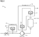
- FIG. 1 a pipeline and instrumentation diagram 11 is shown, which a user has created using the system planning tool 3.
- This diagram has symbols 12 to 17 which represent field devices or PLT (process control technology) points of a field device level.
- the symbols 16, 17 are identified or marked by a border 18, these symbols 16, 17 or this border 18 being assigned to a first simulation unit instance 19, which is connected to the bus 10 ( Figure 1 ) represents connectable real first simulation unit.
- a second simulation unit instance 21, which is also connected to the bus 10 ( Figure 1 ) represents connectable real second simulation unit, assigned the symbol 13 or a border 20.
- the system planning tool creates device hierarchy overviews so that the user can clearly identify the assignments made between the field devices or PCT points to the simulation units. These overviews show the user - without having to open the piping and instrumentation diagram - the simulated and real PCT points and their assignments to the simulation units.
- Figure 3 shows an example of a device hierarchy overview 22 of a subsystem, with descriptions and labels being shown in this overview 22 which represent real and virtual field devices or PCT points as well as simulation units for this subsystem.
- the terms “designations and labels” are used below for the terms that are represented by these “designations and labels", that is, the terms “real field devices or PCT points", “virtual field devices or PCT points””and” Simulation Units ".
- this device hierarchy overview 22 shows the user which real PCT points 23 and which simulation units the subsystem includes and also which of the real PCT points 23 are simulated by which simulation unit 24, 25, 26 be, where the PCE points listed in the simulation units 24 to 26 are designed as virtual PCE points, each of which represents a real PCE point.
- the simulation unit 24 has two virtual PCT points 27 which are assigned to the corresponding real PCT points.
- the simulation unit 25 is provided with three virtual PCE points 28, which are also assigned to the corresponding real PCE points.
- the further simulation unit 27 is provided as a reserve simulation unit to which no PCE points have yet been assigned.
- the field-related components (field device level, field devices, PCT points) are put into operation and tested virtually.
- the simulation units virtualize the field level and the process behavior of the components close to the field is reflected by the at least one (behavior) model in the simulation framework 6.
- the user can gradually commission the virtual components according to a commissioning plan and, in the event that no malfunctions occur, gradually replace the virtual components with the real components.
- the simulation units are designed to report to the system planning tool 3 which virtual components are fault-free or faulty. This means that the simulation units always transmit or report back to this system planning tool 3 their current states or their virtual components.
- the user can in the device hierarchy overview 22 this component of another simulation unit by means of a suitable operator input - z. B. by means of a "Cut &Paste" - or "Drag &Drop” input - assign. This means that the corresponding component is shifted to the other simulation unit, the system planning tool 3 automatically adopting this change in the pipeline and instrumentation diagram.
- FIG Figure 4 shows a section of the device hierarchy overview 22 ( Figure 3 ), in which the simulation units 24, 25, 26 and the virtualized PCE points 27, 28 are shown. It is assumed that two virtual PCT points were already replaced by corresponding real PCT points during commissioning, which is indicated to the user by a suitable marking 29. Another marking 30, 31 indicates to the user which virtual PCE points are fault-free during commissioning and which are faulty or overloaded. In the present example, the virtual PCE point 28a of the simulation unit 25 is disturbed. In order to eliminate this disturbance, the user moves this PCE point 28 into the simulation unit 24, which is indicated in the drawing by means of the arrow 32.
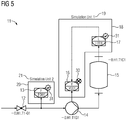
- the system planning tool ensures that these states displayed in the device hierarchy overview 22 are reported back to the diagram and displayed ( Figure 5 ).
- the system planning tool can bring the virtual components for commissioning "into the field" and, conversely, the current status of the simulation units - as well as the results of commissioning - can be read back into the system planning tool.
- This process is thus bidirectional, whereby it is advantageous that the status of the commissioning is reflected. It can be derived like the commissioning process runs or extrapolates when the commissioning will be completed. The knowledge gained during commissioning can also be documented on these objects in the system planning tool. This documentation can be used to insert this at a suitable point when the automation is expanded at a later date and not at points that were already overloaded during commissioning in the past.
Landscapes
- Engineering & Computer Science (AREA)
- Physics & Mathematics (AREA)
- General Physics & Mathematics (AREA)
- Automation & Control Theory (AREA)
- Manufacturing & Machinery (AREA)
- Human Computer Interaction (AREA)
- General Engineering & Computer Science (AREA)
- Quality & Reliability (AREA)
- Programmable Controllers (AREA)
- Testing And Monitoring For Control Systems (AREA)
- Management, Administration, Business Operations System, And Electronic Commerce (AREA)
Claims (5)
- Système de conduite de processus comprenant- un système (2) d'ingénierie- pour l'établissement de projets de composants (5, 8) d'automatisation d'une installation technique, les composants (5, 8) d'automatisation comprenant au moins une commande (5) et des appareils (8) sur site, qui sont reliés à cette commande (5) et auxquels sont affectés des adresses d'appareils sur site, et- pour l'établissement d'au moins un programme de commande, ainsi que pour la charge du programme de commande dans la commande (5),- un framework (6) de simulation pour la modélisation du comportement en processus des appareils (8) sur site,- au moins une unité (7) de simulation pour la virtualisation du comportement en communication des appareils (8) sur site réels et pour le rattachement du comportement en processus modélisé à la au moins une commande (5),- un outil (3) de planification d'installation pour l'établissement de projets des composants techniques de procédé de l'installation, dans lequel, au moyen de l'outil (3) de planification d'installation, il peut être établi par un utilisateur un diagramme (11) de canalisation et d'instrumentation, qui comprend des symboles pour les appareils (8) sur site réels,dans lequel le système (2) d'ingénierie est constitué pour transmettre les adresses d'appareils sur site à l'outil (3) de planification d'installation,
et dans lequel l'outil (3) de planification d'installation est constitué pour combiner au moins l'un des appareils (8) sur site à la au moins une unité (7) de simulation,
et dans lequel l'outil (3) de planification d'installation est constitué pour associer l'adresse du au moins un appareil (8) sur site à la au moins une unité (7) de simulation. - Système de conduite de processus suivant la revendication 1, caractérisé en ce que la combinaison peut être lancée par le fait qu'un utilisateur repère au moyen d'une entrée de commande un symbole (12 à 17) ou un objet-image du au moins un appareil sur site dans le diagramme (11) de canalisation et d'instrumentalisation, dans lequel, sur la base du repérage, l'outil (3) de planification d'installation associe l'adresse du au moins un appareil sur site à la au moins une unité de simulation.
- Système de conduite de processus suivant la revendication 1 ou 2, caractérisé en ce que la au moins une unité (7) de simulation est constituée pour transmettre, pendant la mise en service, son état et/ou l'état des appareils sur site virtuels à l'outil (3) de planification d'installation.
- Système de conduite de processus suivant la revendication 3, caractérisé en ce que l'outil (3) de planification d'installation est constitué pour afficher l'état dans le diagramme (11) de canalisation et d'instrumentalisation et/ou dans une vue (22) d'ensemble hiérarchique d'appareils.
- Outil (3) de planification d'installation constitué et conçu suivant l'une des revendications 1 à 4, pour l'établissement de projets des composants techniques de procédé de l'installation, dans lequel, au moyen de l'outil (3) de planification d'installation, il peut être établi par un utilisateur un diagramme (11) de canalisation et d'instrumentalisation, qui comprend des symboles pour les appareils (8) sur site réels, dans lequel les adresses d'appareils sur site peuvent être transmises par le système (2) d'ingénierie à l'outil (3) de planification d'installation et dans lequel l'outil de planification d'installation est constitué pour combiner au moins l'un des appareils (8) sur site à la au moins une unité (7) de simulation et pour associer l'adresse du au moins un appareil (8) sur site à la au moins une unité (7) de simulation.
Priority Applications (3)
| Application Number | Priority Date | Filing Date | Title |
|---|---|---|---|
| EP16204636.1A EP3336631B1 (fr) | 2016-12-16 | 2016-12-16 | Système d'organisation de procédure et outil de planification d'installations |
| US15/839,383 US10671040B2 (en) | 2016-12-16 | 2017-12-12 | Process control system and plant planning tool |
| CN201711343680.7A CN108205264A (zh) | 2016-12-16 | 2017-12-14 | 过程控制系统以及设施规划工具 |
Applications Claiming Priority (1)
| Application Number | Priority Date | Filing Date | Title |
|---|---|---|---|
| EP16204636.1A EP3336631B1 (fr) | 2016-12-16 | 2016-12-16 | Système d'organisation de procédure et outil de planification d'installations |
Publications (2)
| Publication Number | Publication Date |
|---|---|
| EP3336631A1 EP3336631A1 (fr) | 2018-06-20 |
| EP3336631B1 true EP3336631B1 (fr) | 2021-06-16 |
Family
ID=57570371
Family Applications (1)
| Application Number | Title | Priority Date | Filing Date |
|---|---|---|---|
| EP16204636.1A Active EP3336631B1 (fr) | 2016-12-16 | 2016-12-16 | Système d'organisation de procédure et outil de planification d'installations |
Country Status (3)
| Country | Link |
|---|---|
| US (1) | US10671040B2 (fr) |
| EP (1) | EP3336631B1 (fr) |
| CN (1) | CN108205264A (fr) |
Family Cites Families (11)
| Publication number | Priority date | Publication date | Assignee | Title |
|---|---|---|---|---|
| US7474929B2 (en) * | 2000-01-20 | 2009-01-06 | Fisher-Rosemount Systems, Inc. | Enhanced tool for managing a process control network |
| DE10136732A1 (de) * | 2001-07-25 | 2003-02-13 | Endress & Hauser Gmbh & Co Kg | Verfahren zum Datenaustausch zwischen einem Bedien-und Beobachtungsprogramm und einem Feldgerät |
| US9983559B2 (en) * | 2002-10-22 | 2018-05-29 | Fisher-Rosemount Systems, Inc. | Updating and utilizing dynamic process simulation in an operating process environment |
| DE10251503A1 (de) | 2002-11-04 | 2004-06-09 | Endress + Hauser Flowtec Ag, Reinach | Verfahren zur Offline-Parametrierung eines Feldgerätes der Prozessautomatisierungstechnik |
| DE602006007151D1 (de) * | 2006-10-24 | 2009-07-16 | Abb Research Ltd | Simulation von Feldgeräten in einem computerbasierten Steuersystem |
| JP4737551B2 (ja) * | 2006-12-11 | 2011-08-03 | 横河電機株式会社 | フィールド機器システムと診断方法 |
| US20080211660A1 (en) * | 2006-11-09 | 2008-09-04 | Yokogawa Electric Corporation | Field device system and field device system diagnosing method |
| CN104407518B (zh) * | 2008-06-20 | 2017-05-31 | 因文西斯系统公司 | 对用于过程控制的实际和仿真设施进行交互的系统和方法 |
| GB2474545B (en) * | 2009-09-24 | 2015-06-24 | Fisher Rosemount Systems Inc | Integrated unified threat management for a process control system |
| CN104330980B (zh) * | 2014-11-03 | 2017-04-05 | 中国科学院广州能源研究所 | 一种基于rt‑lab的微电网仿真测试系统 |
| US10878140B2 (en) * | 2016-07-27 | 2020-12-29 | Emerson Process Management Power & Water Solutions, Inc. | Plant builder system with integrated simulation and control system configuration |
-
2016
- 2016-12-16 EP EP16204636.1A patent/EP3336631B1/fr active Active
-
2017
- 2017-12-12 US US15/839,383 patent/US10671040B2/en active Active
- 2017-12-14 CN CN201711343680.7A patent/CN108205264A/zh active Pending
Also Published As
| Publication number | Publication date |
|---|---|
| CN108205264A (zh) | 2018-06-26 |
| EP3336631A1 (fr) | 2018-06-20 |
| US20180173183A1 (en) | 2018-06-21 |
| US10671040B2 (en) | 2020-06-02 |
Similar Documents
| Publication | Publication Date | Title |
|---|---|---|
| EP2453326B1 (fr) | Procédé et système destinés à la commande d'une machine issue de la technique d'automatisation | |
| DE102011105141A1 (de) | Verfahren und system zur simulation eines arbeitsprozesses an einer werkzeugmaschine | |
| DE102010029952A1 (de) | Verfahren zum Integrieren von zumindest einem Feldgerät in ein Netzwerk der Automatisierungstechnik | |
| DE102009019088A1 (de) | Sicherheitssteuerung zum Steuern einer automatisierten Anlage und Verfahren zum Erstellen eines Anwenderprogramms für eine Sicherheitssteuerung | |
| DE112011104923T5 (de) | Engineering-Vorrichtung | |
| EP1947568A1 (fr) | Procédé destiné à l'observation d'un appareil de commande | |
| DE102007054662A1 (de) | Feldgerät | |
| DE102008026409A1 (de) | Bedienungstrainingsystem und Bedienungstrainingverfahren | |
| EP3058425B1 (fr) | Dispositif et procédé permettant de modifier les réglages opérationnels d'une installation technique | |
| EP1658535B1 (fr) | Procede de projection graphique de la commande d'une installation technique a projection integree d'appareils d'exploitation | |
| EP2520991A1 (fr) | Procédé d'accès commandé au comportement d'un sous-module | |
| EP3088976B1 (fr) | Procédé de fonctionnement d'un dispositif d'automatisation et dispositif d'automatisation | |
| DE102014219711A1 (de) | Verfahren zur Kraftwerkssimulation | |
| EP3252549B1 (fr) | Procédé de fonctionnement d'un dispositif d'automatisation et procédé d'automatisation | |
| EP2985663A1 (fr) | Procédé de simulation d'une installation industrielle automatisée | |
| EP3336631B1 (fr) | Système d'organisation de procédure et outil de planification d'installations | |
| EP3931653A1 (fr) | Procédé d'ingénierie et de simulation d'un système d'automatisation au moyen de jumeaux numériques | |
| DE102014219709A1 (de) | Verfahren zur Kraftwerkssimulation für Test- und Schulungszwecke mittels einer verteilten Simulationshardware | |
| EP3082001B1 (fr) | Procédé d'extension d'un dispositif d'automatisation avec un virtuel appareil d'automatisation et dispositif d'automatisation | |
| DE102009009293A1 (de) | Verfahren und System zum Engineering einer Automatisierung zumindest eines Teils einer technischen Anlage | |
| WO2015124320A1 (fr) | Commande à programme enregistré dynamique servant à émuler un appareil de commande | |
| EP2126643B1 (fr) | Procédé d'échange de composants structurels pour un système d'automatisation | |
| DE10119151A1 (de) | Diagnose-Einrichtung für einen Feldbus mit steuerungsunabhängiger Informationsübermittlung | |
| DE10394242T5 (de) | Verfahren und Instrument zur Zuweisung von Rechenressourcen in einem verteilten Steuersystem | |
| DE10253062A1 (de) | Anordnung zum Parametrieren von rechnergestützt arbeitenden Geräten |
Legal Events
| Date | Code | Title | Description |
|---|---|---|---|
| PUAI | Public reference made under article 153(3) epc to a published international application that has entered the european phase |
Free format text: ORIGINAL CODE: 0009012 |
|
| STAA | Information on the status of an ep patent application or granted ep patent |
Free format text: STATUS: THE APPLICATION HAS BEEN PUBLISHED |
|
| AK | Designated contracting states |
Kind code of ref document: A1 Designated state(s): AL AT BE BG CH CY CZ DE DK EE ES FI FR GB GR HR HU IE IS IT LI LT LU LV MC MK MT NL NO PL PT RO RS SE SI SK SM TR |
|
| AX | Request for extension of the european patent |
Extension state: BA ME |
|
| STAA | Information on the status of an ep patent application or granted ep patent |
Free format text: STATUS: REQUEST FOR EXAMINATION WAS MADE |
|
| 17P | Request for examination filed |
Effective date: 20181205 |
|
| RBV | Designated contracting states (corrected) |
Designated state(s): AL AT BE BG CH CY CZ DE DK EE ES FI FR GB GR HR HU IE IS IT LI LT LU LV MC MK MT NL NO PL PT RO RS SE SI SK SM TR |
|
| STAA | Information on the status of an ep patent application or granted ep patent |
Free format text: STATUS: REQUEST FOR EXAMINATION WAS MADE |
|
| GRAP | Despatch of communication of intention to grant a patent |
Free format text: ORIGINAL CODE: EPIDOSNIGR1 |
|
| STAA | Information on the status of an ep patent application or granted ep patent |
Free format text: STATUS: GRANT OF PATENT IS INTENDED |
|
| RIC1 | Information provided on ipc code assigned before grant |
Ipc: G05B 19/418 20060101AFI20210317BHEP |
|
| INTG | Intention to grant announced |
Effective date: 20210401 |
|
| GRAS | Grant fee paid |
Free format text: ORIGINAL CODE: EPIDOSNIGR3 |
|
| GRAA | (expected) grant |
Free format text: ORIGINAL CODE: 0009210 |
|
| STAA | Information on the status of an ep patent application or granted ep patent |
Free format text: STATUS: THE PATENT HAS BEEN GRANTED |
|
| AK | Designated contracting states |
Kind code of ref document: B1 Designated state(s): AL AT BE BG CH CY CZ DE DK EE ES FI FR GB GR HR HU IE IS IT LI LT LU LV MC MK MT NL NO PL PT RO RS SE SI SK SM TR |
|
| REG | Reference to a national code |
Ref country code: GB Ref legal event code: FG4D Free format text: NOT ENGLISH |
|
| REG | Reference to a national code |
Ref country code: CH Ref legal event code: EP |
|
| REG | Reference to a national code |
Ref country code: DE Ref legal event code: R096 Ref document number: 502016013230 Country of ref document: DE |
|
| REG | Reference to a national code |
Ref country code: AT Ref legal event code: REF Ref document number: 1402858 Country of ref document: AT Kind code of ref document: T Effective date: 20210715 |
|
| REG | Reference to a national code |
Ref country code: IE Ref legal event code: FG4D Free format text: LANGUAGE OF EP DOCUMENT: GERMAN |
|
| REG | Reference to a national code |
Ref country code: LT Ref legal event code: MG9D |
|
| PG25 | Lapsed in a contracting state [announced via postgrant information from national office to epo] |
Ref country code: LT Free format text: LAPSE BECAUSE OF FAILURE TO SUBMIT A TRANSLATION OF THE DESCRIPTION OR TO PAY THE FEE WITHIN THE PRESCRIBED TIME-LIMIT Effective date: 20210616 Ref country code: FI Free format text: LAPSE BECAUSE OF FAILURE TO SUBMIT A TRANSLATION OF THE DESCRIPTION OR TO PAY THE FEE WITHIN THE PRESCRIBED TIME-LIMIT Effective date: 20210616 Ref country code: BG Free format text: LAPSE BECAUSE OF FAILURE TO SUBMIT A TRANSLATION OF THE DESCRIPTION OR TO PAY THE FEE WITHIN THE PRESCRIBED TIME-LIMIT Effective date: 20210916 Ref country code: HR Free format text: LAPSE BECAUSE OF FAILURE TO SUBMIT A TRANSLATION OF THE DESCRIPTION OR TO PAY THE FEE WITHIN THE PRESCRIBED TIME-LIMIT Effective date: 20210616 |
|
| REG | Reference to a national code |
Ref country code: NL Ref legal event code: MP Effective date: 20210616 |
|
| PG25 | Lapsed in a contracting state [announced via postgrant information from national office to epo] |
Ref country code: RS Free format text: LAPSE BECAUSE OF FAILURE TO SUBMIT A TRANSLATION OF THE DESCRIPTION OR TO PAY THE FEE WITHIN THE PRESCRIBED TIME-LIMIT Effective date: 20210616 Ref country code: SE Free format text: LAPSE BECAUSE OF FAILURE TO SUBMIT A TRANSLATION OF THE DESCRIPTION OR TO PAY THE FEE WITHIN THE PRESCRIBED TIME-LIMIT Effective date: 20210616 Ref country code: NO Free format text: LAPSE BECAUSE OF FAILURE TO SUBMIT A TRANSLATION OF THE DESCRIPTION OR TO PAY THE FEE WITHIN THE PRESCRIBED TIME-LIMIT Effective date: 20210916 Ref country code: GR Free format text: LAPSE BECAUSE OF FAILURE TO SUBMIT A TRANSLATION OF THE DESCRIPTION OR TO PAY THE FEE WITHIN THE PRESCRIBED TIME-LIMIT Effective date: 20210917 Ref country code: LV Free format text: LAPSE BECAUSE OF FAILURE TO SUBMIT A TRANSLATION OF THE DESCRIPTION OR TO PAY THE FEE WITHIN THE PRESCRIBED TIME-LIMIT Effective date: 20210616 |
|
| PG25 | Lapsed in a contracting state [announced via postgrant information from national office to epo] |
Ref country code: EE Free format text: LAPSE BECAUSE OF FAILURE TO SUBMIT A TRANSLATION OF THE DESCRIPTION OR TO PAY THE FEE WITHIN THE PRESCRIBED TIME-LIMIT Effective date: 20210616 Ref country code: CZ Free format text: LAPSE BECAUSE OF FAILURE TO SUBMIT A TRANSLATION OF THE DESCRIPTION OR TO PAY THE FEE WITHIN THE PRESCRIBED TIME-LIMIT Effective date: 20210616 Ref country code: SK Free format text: LAPSE BECAUSE OF FAILURE TO SUBMIT A TRANSLATION OF THE DESCRIPTION OR TO PAY THE FEE WITHIN THE PRESCRIBED TIME-LIMIT Effective date: 20210616 Ref country code: SM Free format text: LAPSE BECAUSE OF FAILURE TO SUBMIT A TRANSLATION OF THE DESCRIPTION OR TO PAY THE FEE WITHIN THE PRESCRIBED TIME-LIMIT Effective date: 20210616 Ref country code: PT Free format text: LAPSE BECAUSE OF FAILURE TO SUBMIT A TRANSLATION OF THE DESCRIPTION OR TO PAY THE FEE WITHIN THE PRESCRIBED TIME-LIMIT Effective date: 20211018 Ref country code: RO Free format text: LAPSE BECAUSE OF FAILURE TO SUBMIT A TRANSLATION OF THE DESCRIPTION OR TO PAY THE FEE WITHIN THE PRESCRIBED TIME-LIMIT Effective date: 20210616 Ref country code: NL Free format text: LAPSE BECAUSE OF FAILURE TO SUBMIT A TRANSLATION OF THE DESCRIPTION OR TO PAY THE FEE WITHIN THE PRESCRIBED TIME-LIMIT Effective date: 20210616 Ref country code: ES Free format text: LAPSE BECAUSE OF FAILURE TO SUBMIT A TRANSLATION OF THE DESCRIPTION OR TO PAY THE FEE WITHIN THE PRESCRIBED TIME-LIMIT Effective date: 20210616 |
|
| PG25 | Lapsed in a contracting state [announced via postgrant information from national office to epo] |
Ref country code: PL Free format text: LAPSE BECAUSE OF FAILURE TO SUBMIT A TRANSLATION OF THE DESCRIPTION OR TO PAY THE FEE WITHIN THE PRESCRIBED TIME-LIMIT Effective date: 20210616 |
|
| REG | Reference to a national code |
Ref country code: DE Ref legal event code: R097 Ref document number: 502016013230 Country of ref document: DE |
|
| PLBE | No opposition filed within time limit |
Free format text: ORIGINAL CODE: 0009261 |
|
| STAA | Information on the status of an ep patent application or granted ep patent |
Free format text: STATUS: NO OPPOSITION FILED WITHIN TIME LIMIT |
|
| PG25 | Lapsed in a contracting state [announced via postgrant information from national office to epo] |
Ref country code: DK Free format text: LAPSE BECAUSE OF FAILURE TO SUBMIT A TRANSLATION OF THE DESCRIPTION OR TO PAY THE FEE WITHIN THE PRESCRIBED TIME-LIMIT Effective date: 20210616 |
|
| 26N | No opposition filed |
Effective date: 20220317 |
|
| PG25 | Lapsed in a contracting state [announced via postgrant information from national office to epo] |
Ref country code: AL Free format text: LAPSE BECAUSE OF FAILURE TO SUBMIT A TRANSLATION OF THE DESCRIPTION OR TO PAY THE FEE WITHIN THE PRESCRIBED TIME-LIMIT Effective date: 20210616 |
|
| PG25 | Lapsed in a contracting state [announced via postgrant information from national office to epo] |
Ref country code: MC Free format text: LAPSE BECAUSE OF FAILURE TO SUBMIT A TRANSLATION OF THE DESCRIPTION OR TO PAY THE FEE WITHIN THE PRESCRIBED TIME-LIMIT Effective date: 20210616 |
|
| REG | Reference to a national code |
Ref country code: CH Ref legal event code: PL |
|
| REG | Reference to a national code |
Ref country code: BE Ref legal event code: MM Effective date: 20211231 |
|
| PG25 | Lapsed in a contracting state [announced via postgrant information from national office to epo] |
Ref country code: LU Free format text: LAPSE BECAUSE OF NON-PAYMENT OF DUE FEES Effective date: 20211216 Ref country code: IE Free format text: LAPSE BECAUSE OF NON-PAYMENT OF DUE FEES Effective date: 20211216 |
|
| PG25 | Lapsed in a contracting state [announced via postgrant information from national office to epo] |
Ref country code: BE Free format text: LAPSE BECAUSE OF NON-PAYMENT OF DUE FEES Effective date: 20211231 |
|
| PG25 | Lapsed in a contracting state [announced via postgrant information from national office to epo] |
Ref country code: LI Free format text: LAPSE BECAUSE OF NON-PAYMENT OF DUE FEES Effective date: 20211231 Ref country code: CH Free format text: LAPSE BECAUSE OF NON-PAYMENT OF DUE FEES Effective date: 20211231 |
|
| REG | Reference to a national code |
Ref country code: AT Ref legal event code: MM01 Ref document number: 1402858 Country of ref document: AT Kind code of ref document: T Effective date: 20211216 |
|
| PG25 | Lapsed in a contracting state [announced via postgrant information from national office to epo] |
Ref country code: AT Free format text: LAPSE BECAUSE OF NON-PAYMENT OF DUE FEES Effective date: 20211216 |
|
| PG25 | Lapsed in a contracting state [announced via postgrant information from national office to epo] |
Ref country code: HU Free format text: LAPSE BECAUSE OF FAILURE TO SUBMIT A TRANSLATION OF THE DESCRIPTION OR TO PAY THE FEE WITHIN THE PRESCRIBED TIME-LIMIT; INVALID AB INITIO Effective date: 20161216 |
|
| PGFP | Annual fee paid to national office [announced via postgrant information from national office to epo] |
Ref country code: GB Payment date: 20230103 Year of fee payment: 7 |
|
| PG25 | Lapsed in a contracting state [announced via postgrant information from national office to epo] |
Ref country code: CY Free format text: LAPSE BECAUSE OF FAILURE TO SUBMIT A TRANSLATION OF THE DESCRIPTION OR TO PAY THE FEE WITHIN THE PRESCRIBED TIME-LIMIT Effective date: 20210616 |
|
| PGFP | Annual fee paid to national office [announced via postgrant information from national office to epo] |
Ref country code: IT Payment date: 20231220 Year of fee payment: 8 Ref country code: FR Payment date: 20231214 Year of fee payment: 8 |
|
| PG25 | Lapsed in a contracting state [announced via postgrant information from national office to epo] |
Ref country code: MK Free format text: LAPSE BECAUSE OF FAILURE TO SUBMIT A TRANSLATION OF THE DESCRIPTION OR TO PAY THE FEE WITHIN THE PRESCRIBED TIME-LIMIT Effective date: 20210616 |
|
| PGFP | Annual fee paid to national office [announced via postgrant information from national office to epo] |
Ref country code: DE Payment date: 20240219 Year of fee payment: 8 Ref country code: GB Payment date: 20240102 Year of fee payment: 8 |