EP3336631B1 - Process control system and system planning tool - Google Patents
Process control system and system planning tool Download PDFInfo
- Publication number
- EP3336631B1 EP3336631B1 EP16204636.1A EP16204636A EP3336631B1 EP 3336631 B1 EP3336631 B1 EP 3336631B1 EP 16204636 A EP16204636 A EP 16204636A EP 3336631 B1 EP3336631 B1 EP 3336631B1
- Authority
- EP
- European Patent Office
- Prior art keywords
- planning tool
- plant
- simulation unit
- simulation
- field devices
- Prior art date
- Legal status (The legal status is an assumption and is not a legal conclusion. Google has not performed a legal analysis and makes no representation as to the accuracy of the status listed.)
- Active
Links
- 238000004886 process control Methods 0.000 title claims description 15
- 238000004088 simulation Methods 0.000 claims description 74
- 238000010586 diagram Methods 0.000 claims description 20
- 238000000034 method Methods 0.000 claims description 15
- 238000010327 methods by industry Methods 0.000 claims description 9
- 238000004891 communication Methods 0.000 claims description 4
- 238000005516 engineering process Methods 0.000 description 2
- 230000002457 bidirectional effect Effects 0.000 description 1
- 230000001627 detrimental effect Effects 0.000 description 1
- 230000007257 malfunction Effects 0.000 description 1
- 230000002093 peripheral effect Effects 0.000 description 1
- 238000004801 process automation Methods 0.000 description 1
Images


Classifications
-
- G—PHYSICS
- G05—CONTROLLING; REGULATING
- G05B—CONTROL OR REGULATING SYSTEMS IN GENERAL; FUNCTIONAL ELEMENTS OF SUCH SYSTEMS; MONITORING OR TESTING ARRANGEMENTS FOR SUCH SYSTEMS OR ELEMENTS
- G05B19/00—Programme-control systems
- G05B19/02—Programme-control systems electric
- G05B19/04—Programme control other than numerical control, i.e. in sequence controllers or logic controllers
- G05B19/042—Programme control other than numerical control, i.e. in sequence controllers or logic controllers using digital processors
- G05B19/0426—Programming the control sequence
-
- G—PHYSICS
- G05—CONTROLLING; REGULATING
- G05B—CONTROL OR REGULATING SYSTEMS IN GENERAL; FUNCTIONAL ELEMENTS OF SUCH SYSTEMS; MONITORING OR TESTING ARRANGEMENTS FOR SUCH SYSTEMS OR ELEMENTS
- G05B17/00—Systems involving the use of models or simulators of said systems
- G05B17/02—Systems involving the use of models or simulators of said systems electric
-
- G—PHYSICS
- G05—CONTROLLING; REGULATING
- G05B—CONTROL OR REGULATING SYSTEMS IN GENERAL; FUNCTIONAL ELEMENTS OF SUCH SYSTEMS; MONITORING OR TESTING ARRANGEMENTS FOR SUCH SYSTEMS OR ELEMENTS
- G05B19/00—Programme-control systems
- G05B19/02—Programme-control systems electric
- G05B19/04—Programme control other than numerical control, i.e. in sequence controllers or logic controllers
- G05B19/05—Programmable logic controllers, e.g. simulating logic interconnections of signals according to ladder diagrams or function charts
- G05B19/056—Programming the PLC
-
- G—PHYSICS
- G05—CONTROLLING; REGULATING
- G05B—CONTROL OR REGULATING SYSTEMS IN GENERAL; FUNCTIONAL ELEMENTS OF SUCH SYSTEMS; MONITORING OR TESTING ARRANGEMENTS FOR SUCH SYSTEMS OR ELEMENTS
- G05B19/00—Programme-control systems
- G05B19/02—Programme-control systems electric
- G05B19/18—Numerical control [NC], i.e. automatically operating machines, in particular machine tools, e.g. in a manufacturing environment, so as to execute positioning, movement or co-ordinated operations by means of programme data in numerical form
- G05B19/406—Numerical control [NC], i.e. automatically operating machines, in particular machine tools, e.g. in a manufacturing environment, so as to execute positioning, movement or co-ordinated operations by means of programme data in numerical form characterised by monitoring or safety
- G05B19/4069—Simulating machining process on screen
-
- G—PHYSICS
- G05—CONTROLLING; REGULATING
- G05B—CONTROL OR REGULATING SYSTEMS IN GENERAL; FUNCTIONAL ELEMENTS OF SUCH SYSTEMS; MONITORING OR TESTING ARRANGEMENTS FOR SUCH SYSTEMS OR ELEMENTS
- G05B19/00—Programme-control systems
- G05B19/02—Programme-control systems electric
- G05B19/418—Total factory control, i.e. centrally controlling a plurality of machines, e.g. direct or distributed numerical control [DNC], flexible manufacturing systems [FMS], integrated manufacturing systems [IMS], computer integrated manufacturing [CIM]
-
- G—PHYSICS
- G05—CONTROLLING; REGULATING
- G05B—CONTROL OR REGULATING SYSTEMS IN GENERAL; FUNCTIONAL ELEMENTS OF SUCH SYSTEMS; MONITORING OR TESTING ARRANGEMENTS FOR SUCH SYSTEMS OR ELEMENTS
- G05B2219/00—Program-control systems
- G05B2219/20—Pc systems
- G05B2219/23—Pc programming
- G05B2219/23054—Simulate response on entered parameters and display, quicker response
-
- G—PHYSICS
- G05—CONTROLLING; REGULATING
- G05B—CONTROL OR REGULATING SYSTEMS IN GENERAL; FUNCTIONAL ELEMENTS OF SUCH SYSTEMS; MONITORING OR TESTING ARRANGEMENTS FOR SUCH SYSTEMS OR ELEMENTS
- G05B2219/00—Program-control systems
- G05B2219/20—Pc systems
- G05B2219/23—Pc programming
- G05B2219/23445—Real time simulation
-
- G—PHYSICS
- G05—CONTROLLING; REGULATING
- G05B—CONTROL OR REGULATING SYSTEMS IN GENERAL; FUNCTIONAL ELEMENTS OF SUCH SYSTEMS; MONITORING OR TESTING ARRANGEMENTS FOR SUCH SYSTEMS OR ELEMENTS
- G05B2219/00—Program-control systems
- G05B2219/20—Pc systems
- G05B2219/25—Pc structure of the system
- G05B2219/25014—Fieldbus general name of bus connected to machines, detectors, actuators
-
- G—PHYSICS
- G05—CONTROLLING; REGULATING
- G05B—CONTROL OR REGULATING SYSTEMS IN GENERAL; FUNCTIONAL ELEMENTS OF SUCH SYSTEMS; MONITORING OR TESTING ARRANGEMENTS FOR SUCH SYSTEMS OR ELEMENTS
- G05B2219/00—Program-control systems
- G05B2219/20—Pc systems
- G05B2219/25—Pc structure of the system
- G05B2219/25428—Field device
-
- G—PHYSICS
- G05—CONTROLLING; REGULATING
- G05B—CONTROL OR REGULATING SYSTEMS IN GENERAL; FUNCTIONAL ELEMENTS OF SUCH SYSTEMS; MONITORING OR TESTING ARRANGEMENTS FOR SUCH SYSTEMS OR ELEMENTS
- G05B2219/00—Program-control systems
- G05B2219/30—Nc systems
- G05B2219/31—From computer integrated manufacturing till monitoring
- G05B2219/31121—Fielddevice, field controller, interface connected to fieldbus
-
- G—PHYSICS
- G05—CONTROLLING; REGULATING
- G05B—CONTROL OR REGULATING SYSTEMS IN GENERAL; FUNCTIONAL ELEMENTS OF SUCH SYSTEMS; MONITORING OR TESTING ARRANGEMENTS FOR SUCH SYSTEMS OR ELEMENTS
- G05B2219/00—Program-control systems
- G05B2219/30—Nc systems
- G05B2219/32—Operator till task planning
- G05B2219/32337—Simulation, statechart SC
-
- Y—GENERAL TAGGING OF NEW TECHNOLOGICAL DEVELOPMENTS; GENERAL TAGGING OF CROSS-SECTIONAL TECHNOLOGIES SPANNING OVER SEVERAL SECTIONS OF THE IPC; TECHNICAL SUBJECTS COVERED BY FORMER USPC CROSS-REFERENCE ART COLLECTIONS [XRACs] AND DIGESTS
- Y02—TECHNOLOGIES OR APPLICATIONS FOR MITIGATION OR ADAPTATION AGAINST CLIMATE CHANGE
- Y02P—CLIMATE CHANGE MITIGATION TECHNOLOGIES IN THE PRODUCTION OR PROCESSING OF GOODS
- Y02P90/00—Enabling technologies with a potential contribution to greenhouse gas [GHG] emissions mitigation
- Y02P90/02—Total factory control, e.g. smart factories, flexible manufacturing systems [FMS] or integrated manufacturing systems [IMS]
Definitions
- the invention relates to a process control system with the measures specified in claim 1.
- the invention also relates to a system planning tool suitable for such a process control system.
- This simulation tool includes a simulation framework that simulates the process behavior of the field device level, and a simulation unit that simulates the communication behavior of the real field devices, this simulation unit also linking the modeled process behavior to the controller.
- Siemens document "Quick and easy creation of pipe and instrumentation diagrams with COMOS P&ID using the practical example, COMOS V10.1, application example 07/2016" is another software tool for creating a pipe and instrumentation diagram (P&ID Flow diagram, pipeline and instrument usage diagram) for a technical system to be controlled.
- This software tool is part of a system planning tool, which is provided for process engineering plant planning.
- WO 2004/042482 A1 discloses a method for offline parameterization of a field device in process automation technology.
- a simulation method is used to simulate the process behavior of the field device.
- the system planning tool on the one hand and the simulation tool, in particular the simulation unit of this simulation tool, on the other hand, do not interact in the state of the art, which means that the engineering of the simulation is detached from the engineering of the process engineering system planning process, which is has a detrimental effect on the commissioning of the process plant.
- the invention is therefore based on the object of creating a process control system which is suitable for commissioning components close to the field. Furthermore, a system planning tool suitable for such a process control system is to be specified.
- linking or "linking” enables a step-by-step and safe commissioning of a process engineering system, the commissioning with virtual system components being part of the system planning.
- the system planning tool can be used to understand the state of commissioning, whereby it is always possible to see which process-related system components are still virtualized and which are actually connected to the controls.
- a consistent engineering of the process engineering System including the consideration of simulation aspects.
- the at least one simulation unit is designed to transmit its status and / or the status of the virtual field devices to the system planning tool during commissioning, whereby the current status of the simulation unit - such as also the results of the commissioning - can be read back into the system planning tool.
- the system planning tool is designed to display the status in the pipeline and instrumentation diagram and / or this status in a device hierarchy overview, the user can identify which virtual field devices or PCT points are fault-free and which are faulty or faulty during commissioning. are overloaded.
- Figure 1 1 denotes components of a process control system which, in the present exemplary embodiment, comprises an engineering system 2, a system planning tool 3, an operator station 4, a controller or automation device 5, a simulation tool 6, 7 and a field device level 8.
- the process control system 1 can of course have a variety of controls 5, which on the one hand via a plant bus 9 with the engineering system 2, the plant planning tool 3 and the operator station 4 and on the other hand via a further bus 10, for.
- the so-called PROFIBUS DP are connected to field device level 8.
- the field device level 8 has a multiplicity of field devices, actuators and sensors being connected to so-called “decentralized peripherals” and / or bus couplers of this field device level 8. Which and how many of the controls and field devices as well as which other automation components are used to control a system depends on the automation task to be solved Automation components configured or "engineered” accordingly.
- the simulation tool 6, 7 comprises a simulation framework 6 and at least one simulation unit 7, with a user using the simulation framework 6 to create at least one model that virtualizes or simulates the process behavior of the field device level 8 (in the drawing by dashed lines indicated).
- the simulation unit 7 is designed to virtualize or simulate the communication behavior of the real field devices of the field level 8 and also designed to connect the process model created by the simulation framework 6 to the controller 5 via the bus 10.
- the simulation unit 7 is connected to the controller 5 and the real field level is separated from the controller 5, which is indicated by a switch 32 in the drawing.
- only one simulation unit 7 is provided for the field device level 8.
- a simulation unit can be used for each strand 10a, 10b of the bus 10, with a user planning the number of simulation units by means of the engineering system 2 or by means of the system planning tool 3.
- the engineering system 2 transmits the addresses of the field devices to each simulation unit as well as the simulation framework 6 and the system planning tool 3, which z. B. are stored in so-called device description files of the field devices, these files from the engineering system 2 can be read out and stored in this.
- the user creates a pipeline and instrumentation diagram (P&ID flow diagram, pipeline and instrument usage diagram) for the technical system to be planned.
- the system planning tool 3 has a “simulation unit” class, from which instances “simulation unit 1, simulation unit 2, ...” can be formed or created.
- the system planning tool 3 generates a first and a second instance from the "simulation unit” class - z. B. the instances "simulation unit 1" and "simulation unit 2".
- the field devices are assigned to one of the entities in such a way that a user first identifies a symbol or an image object of one of the field devices in the pipeline and instrumentation diagram by means of a suitable operator input and B. by another input - assigned to the instance.
- the system planning tool 3 automatically links the address of the field device, which is represented by the symbol, with the simulation unit, which is represented by the one instance. This means that the simulation unit is "integrated" into the system planning tool 3 and this enables a corresponding virtualization to be taken into account in the process engineering planning and also (dynamically) to change and maintain it in the further course of the planning.
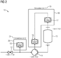
- FIG. 1 a pipeline and instrumentation diagram 11 is shown, which a user has created using the system planning tool 3.
- This diagram has symbols 12 to 17 which represent field devices or PLT (process control technology) points of a field device level.
- the symbols 16, 17 are identified or marked by a border 18, these symbols 16, 17 or this border 18 being assigned to a first simulation unit instance 19, which is connected to the bus 10 ( Figure 1 ) represents connectable real first simulation unit.
- a second simulation unit instance 21, which is also connected to the bus 10 ( Figure 1 ) represents connectable real second simulation unit, assigned the symbol 13 or a border 20.
- the system planning tool creates device hierarchy overviews so that the user can clearly identify the assignments made between the field devices or PCT points to the simulation units. These overviews show the user - without having to open the piping and instrumentation diagram - the simulated and real PCT points and their assignments to the simulation units.
- Figure 3 shows an example of a device hierarchy overview 22 of a subsystem, with descriptions and labels being shown in this overview 22 which represent real and virtual field devices or PCT points as well as simulation units for this subsystem.
- the terms “designations and labels” are used below for the terms that are represented by these “designations and labels", that is, the terms “real field devices or PCT points", “virtual field devices or PCT points””and” Simulation Units ".
- this device hierarchy overview 22 shows the user which real PCT points 23 and which simulation units the subsystem includes and also which of the real PCT points 23 are simulated by which simulation unit 24, 25, 26 be, where the PCE points listed in the simulation units 24 to 26 are designed as virtual PCE points, each of which represents a real PCE point.
- the simulation unit 24 has two virtual PCT points 27 which are assigned to the corresponding real PCT points.
- the simulation unit 25 is provided with three virtual PCE points 28, which are also assigned to the corresponding real PCE points.
- the further simulation unit 27 is provided as a reserve simulation unit to which no PCE points have yet been assigned.
- the field-related components (field device level, field devices, PCT points) are put into operation and tested virtually.
- the simulation units virtualize the field level and the process behavior of the components close to the field is reflected by the at least one (behavior) model in the simulation framework 6.
- the user can gradually commission the virtual components according to a commissioning plan and, in the event that no malfunctions occur, gradually replace the virtual components with the real components.
- the simulation units are designed to report to the system planning tool 3 which virtual components are fault-free or faulty. This means that the simulation units always transmit or report back to this system planning tool 3 their current states or their virtual components.
- the user can in the device hierarchy overview 22 this component of another simulation unit by means of a suitable operator input - z. B. by means of a "Cut &Paste" - or "Drag &Drop” input - assign. This means that the corresponding component is shifted to the other simulation unit, the system planning tool 3 automatically adopting this change in the pipeline and instrumentation diagram.
- FIG Figure 4 shows a section of the device hierarchy overview 22 ( Figure 3 ), in which the simulation units 24, 25, 26 and the virtualized PCE points 27, 28 are shown. It is assumed that two virtual PCT points were already replaced by corresponding real PCT points during commissioning, which is indicated to the user by a suitable marking 29. Another marking 30, 31 indicates to the user which virtual PCE points are fault-free during commissioning and which are faulty or overloaded. In the present example, the virtual PCE point 28a of the simulation unit 25 is disturbed. In order to eliminate this disturbance, the user moves this PCE point 28 into the simulation unit 24, which is indicated in the drawing by means of the arrow 32.
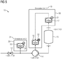
- the system planning tool ensures that these states displayed in the device hierarchy overview 22 are reported back to the diagram and displayed ( Figure 5 ).
- the system planning tool can bring the virtual components for commissioning "into the field" and, conversely, the current status of the simulation units - as well as the results of commissioning - can be read back into the system planning tool.
- This process is thus bidirectional, whereby it is advantageous that the status of the commissioning is reflected. It can be derived like the commissioning process runs or extrapolates when the commissioning will be completed. The knowledge gained during commissioning can also be documented on these objects in the system planning tool. This documentation can be used to insert this at a suitable point when the automation is expanded at a later date and not at points that were already overloaded during commissioning in the past.
Description
Die Erfindung betrifft ein Prozessleitsystem mit den im Patentanspruch 1 angegebenen Maßnahmen. Darüber hinaus betrifft die Erfindung ein für ein derartiges Prozessleitsystem geeignetes Anlagenplanungs-Werkzeug.The invention relates to a process control system with the measures specified in
Aus dem
Aus dem
Darüber hinaus ist aus dem Siemens-Dokument "Schnelle und einfache Erstellung von Rohrleitungs- und Instrumentierungsschema mit COMOS P&ID am praktischen Beispiel, COMOS V10.1, Anwendungsbeispiel 07/2016" ein weiteres Software-Werkzeug zur Erstellung eines Rohrleitungs- und Instrumentierungsdiagramms (R&I-Fließschema, Rohrleitungs- und Instrumentenfleißschema) für eine zu steuernde technische Anlage bekannt. Dieses Software-Werkzeug ist Bestandteil eines Anlagenplanungs-Werkzeugs, welches zur verfahrenstechnischen Anlagenplanung vorgesehen ist.In addition, the Siemens document "Quick and easy creation of pipe and instrumentation diagrams with COMOS P&ID using the practical example, COMOS V10.1, application example 07/2016" is another software tool for creating a pipe and instrumentation diagram (P&ID Flow diagram, pipeline and instrument usage diagram) for a technical system to be controlled. This software tool is part of a system planning tool, which is provided for process engineering plant planning.
In der
Das Anlagenplanungs-Werkzeug einerseits und das Simulations-Werkzeug, insbesondere die Simulations-Einheit dieses Simulations-Werkzeugs, andererseits stehen beim Stand der Technik in keiner Wechselwirkung, was bedeutet, dass das Engineering der Simulation von dem Engineering des verfahrenstechnischen Anlagenplanungsprozesses losgelöst ist, was sich nachteilig auf die Inbetriebnahme der verfahrenstechnischen Anlage auswirkt.The system planning tool on the one hand and the simulation tool, in particular the simulation unit of this simulation tool, on the other hand, do not interact in the state of the art, which means that the engineering of the simulation is detached from the engineering of the process engineering system planning process, which is has a detrimental effect on the commissioning of the process plant.
Der Erfindung liegt daher die Aufgabe zugrunde ein Prozessleitsystem zu schaffen, die für eine Inbetriebnahme von feldnahen Komponenten geeignet ist. Ferner ist ein für ein derartiges Prozessleitsystem geeignetes Anlagenplanungs-Werkzeug anzugeben.The invention is therefore based on the object of creating a process control system which is suitable for commissioning components close to the field. Furthermore, a system planning tool suitable for such a process control system is to be specified.
Diese Aufgabe wird im Hinblick auf das Prozessleitsystem durch die im Anspruchs 1, bezüglich des Anlagenplanungs-Werkzeugs durch die im Anspruch 5 angegebenen Maßnahmen gelöst.With regard to the process control system, this object is achieved by the measures specified in
Vorteilhaft ist, dass durch eine derartige Verknüpfung oder "Verlinkung" eine stufenweise und sichere Inbetriebnahme einer verfahrenstechnischen Anlage ermöglicht wird, wobei die Inbetriebnahme mit virtuellen Anlagenkomponenten Bestandteil der Anlagenplanung ist. Mittels des Anlagenplanungswerkzeugs kann der Zustand der Inbetriebnahme nachvollzogen werden, wobei jederzeit nachvollziehbar ist, welche verfahrenstechnischen Anlagenkomponenten noch virtualisiert sind und welche bereits real an die Steuerungen angebunden sind. Darüber hinaus wird ein durchgängiges Engineering der verfahrenstechnischen Anlage inklusive der Berücksichtigung von Simulationsaspekten ermöglicht.It is advantageous that such a linking or "linking" enables a step-by-step and safe commissioning of a process engineering system, the commissioning with virtual system components being part of the system planning. The system planning tool can be used to understand the state of commissioning, whereby it is always possible to see which process-related system components are still virtualized and which are actually connected to the controls. In addition, a consistent engineering of the process engineering System including the consideration of simulation aspects.
Mittels der im Anspruch 2 angegebenen Maßnahmen kann ein Anwender eine Verknüpfung einfach bewerkstelligenBy means of the measures specified in
In einer weiteren Ausgestaltung der Erfindung ist vorgesehen, dass die zumindest eine Simulations-Einheit dazu ausgebildet ist, während der Inbetriebnahme ihren Zustand und/oder den Zustand der virtuellen Feldgeräte dem Anlagenplanungs-Werkzeug zu übermitteln, wodurch der aktuelle Zustand der Simulations-Einheit - wie auch die Ergebnisse der Inbetriebnahme - wieder ins Anlagenplanungs-Werkzeug zurückgelesen werden können.In a further embodiment of the invention it is provided that the at least one simulation unit is designed to transmit its status and / or the status of the virtual field devices to the system planning tool during commissioning, whereby the current status of the simulation unit - such as also the results of the commissioning - can be read back into the system planning tool.
Dadurch, dass das Anlagenplanungs-Werkzeug dazu ausgebildet ist, den Zustand im Rohrleitungs- und Instrumentierungsdiagramm und/oder diesen Zustand in einer Gerätehierarchieübersicht anzuzeigen, kann der Anwender erkennen, welche virtuellen Feldgeräte bzw. PLT-Stellen während der Inbetriebnahme störungsfrei und welche fehlerhaft bzw. überlastet sind.Because the system planning tool is designed to display the status in the pipeline and instrumentation diagram and / or this status in a device hierarchy overview, the user can identify which virtual field devices or PCT points are fault-free and which are faulty or faulty during commissioning. are overloaded.
Anhand der Zeichnung, in der ein Ausführungsbeispiel der Erfindung veranschaulicht ist, werden im Folgenden die Erfindung, deren Ausgestaltungen sowie Vorteile näher erläutert.With reference to the drawing, in which an embodiment of the invention is illustrated, the invention, its configurations and advantages are explained in more detail below.
Es zeigen in einer vereinfachten Form
Figur 1- Bestandteile eines Prozessleitsystems,
Figur 2 und 5- Rohrleitungs- und Instrumentierungsdiagramme und,
- Figur 3 und 4
- Gerätehierarchieübersichten.
- Figure 1
- Components of a process control system,
- Figures 2 and 5
- Piping and instrumentation diagrams and,
- Figures 3 and 4
- Device hierarchy overviews.
Die in den
In
Das Simulations-Werkzeug 6, 7 umfasst ein Simulations-Framework 6 und mindestens eine Simulations-Einheit 7, wobei ein Anwender mittels des Simulations-Frameworks 6 zumindest ein Modell erstellt, welches das Prozessverhalten der Feldgeräteebene 8 virtualisiert bzw. simuliert (in der Zeichnung durch gestrichelte Linien angedeutet). Die Simulations-Einheit 7 ist dazu ausgebildet, das Kommunikationsverhalten der realen Feldgeräte der Feldebene 8 zu virtualisieren bzw. zu simulieren und darüber hinaus dazu ausgebildet, das durch das Simulations-Framework 6 erstellte Prozessmodell über den Bus 10 an die Steuerung 5 anzubinden. In dieser Betriebsart "Virtualisierung" ist die Simulations-Einheit 7 mit der Steuerung 5 verbunden und die reale Feldebene von der Steuerung 5 getrennt, was in der Zeichnung durch einen Schalter 32 angedeutet ist. Im vorliegenden Ausführungsbeispiel ist lediglich eine Simulations-Einheit 7 für die Feldgeräteebene 8 vorgesehen. Selbstverständlich kann für jeden Strang 10a, 10b des Busses 10 eine Simulations-Einheit eingesetzt werden, wobei ein Anwender mittels des Engineering-Systems 2 oder mittels des Anlagenplanungs-Werkzeugs 3 die Anzahl der Simulations-Einheiten projektiert. Das Engineering-System 2 übermittelt jeder Simulations-Einheit sowie dem Simulations-Framework 6 und dem Anlagenplanungs-Werkzeugs 3 die Adressen der Feldgeräte, die z. B. in so genannten Gerätebeschreibungs-Dateien der Feldgeräte hinterlegt sind, wobei diese Dateien vom Engineering-System 2 ausgelesen und in diesem abgespeichert werden.The simulation tool 6, 7 comprises a simulation framework 6 and at least one simulation unit 7, with a user using the simulation framework 6 to create at least one model that virtualizes or simulates the process behavior of the field device level 8 (in the drawing by dashed lines indicated). The simulation unit 7 is designed to virtualize or simulate the communication behavior of the real field devices of the field level 8 and also designed to connect the process model created by the simulation framework 6 to the controller 5 via the
Mittels des zur verfahrenstechnischen Anlagenplanung vorgesehenen Anlagenplanungs-Werkzeugs 3 erstellt der Anwender ein Rohrleitungs- und Instrumentierungsdiagramm (R&I-Fließschema, Rohrleitungs- und Instrumentenfleißschema) für die zu projektierende technische Anlage. Das Anlagenplanungs-Werkzeug 3 weist eine Klasse "Simulations-Einheit" auf, aus welchen Instanzen "Simulations-Einheit 1, Simulations-Einheit 2, ..." gebildet bzw. angelegt werden können. Für den Fall, dass z. B. zwei Simulations-Einheiten zu projektieren sind, erzeugt das Anlagenplanungs-Werkzeug 3 aus der Klasse "Simulations-Einheit" eine erste und eine zweite Instanz - z. B. die Instanzen "Simulations-Einheit 1" und "Simulations-Einheit 2".Using the system planning tool 3 provided for process engineering system planning, the user creates a pipeline and instrumentation diagram (P&ID flow diagram, pipeline and instrument usage diagram) for the technical system to be planned. The system planning tool 3 has a “simulation unit” class, from which instances “
Die Zuordnung der Feldgeräte zu einer der Instanzen erfolgt in der Art und Weise, dass ein Anwender zunächst mittels einer geeigneten Bedieneingabe ein Symbol bzw. ein Bildobjekt eines der Feldgeräte im Rohrleitungs- und Instrumentierungsdiagramm kennzeichnet und - z. B. durch eine weitere Eingabe - der Instanz zuordnet. Dadurch verknüpft das Anlagenplanungs-Werkzeug 3 automatisch die Adresse des Feldgerätes, das durch das Symbol repräsentiert wird, mit der Simulations-Einheit, die durch die eine Instanz repräsentiert wird. Dies bedeutet, dass die Simulations-Einheit in das Anlagenplanungs-Werkzeug 3 "integriert" ist und es dadurch ermöglicht wird, bereits in der verfahrenstechnischen Planung eine entsprechende Virtualisierung mit zu berücksichtigen und im weiteren Planungsverlauf auch (dynamisch) zu ändern und zu pflegen.The field devices are assigned to one of the entities in such a way that a user first identifies a symbol or an image object of one of the field devices in the pipeline and instrumentation diagram by means of a suitable operator input and B. by another input - assigned to the instance. As a result, the system planning tool 3 automatically links the address of the field device, which is represented by the symbol, with the simulation unit, which is represented by the one instance. This means that the simulation unit is "integrated" into the system planning tool 3 and this enables a corresponding virtualization to be taken into account in the process engineering planning and also (dynamically) to change and maintain it in the further course of the planning.
Im Folgenden wird auf
Damit der Anwender eindeutig die getroffenen Zuordnungen der Feldgeräte bzw. PLT-Stellen zu den Simulations-Einheiten erkennen kann, erstellt das Anlagenplanungs-Werkzeug Gerätehierarchieübersichten. Diese Übersichten zeigen dem Anwender - ohne das Rohrleitungs- und Instrumentierungsdiagramm öffnen zu müssen - die simulierten und realen PLT-Stellen und deren Zuordnungen zu den Simulations-Einheiten an.The system planning tool creates device hierarchy overviews so that the user can clearly identify the assignments made between the field devices or PCT points to the simulation units. These overviews show the user - without having to open the piping and instrumentation diagram - the simulated and real PCT points and their assignments to the simulation units.
Zur näheren Erläuterung wird dazu auf die
Dem Anwender wird im vorliegenden Beispiel durch diese Gerätehierarchie-Übersicht 22 angezeigt, welche reale PLT-Stellen 23 und welche Simulations-Einheiten die Teilanlage umfasst und darüber hinaus, welche der realen PLT-Stellen 23 von welcher Simulations-Einheit 24, 25, 26 simuliert werden, wobei die in den Simulations-Einheiten 24 bis 26 aufgeführten PLT-Stellen als virtuelle PLT-Stellen ausgebildet sind, die jeweils eine reale PLT-Stelle repräsentieren. Beispielsweise weist die Simulations-Einheit 24 zwei virtuelle PLT-Stellen 27 auf, die den entsprechenden realen PLT-Stellen zugeordnet sind. Ferner ist die Simulations-Einheit 25 mit drei virtuellen PLT-Stellen 28 versehen, welche ebenfalls den dazu entsprechenden realen PLT-Stellen zugeordnet sind. Die weitere Simulations-Einheit 27 ist als Reserve-Simulations-Einheit vorgesehen, welcher noch keine PLT-Stellen zugeordnet sind.In the present example, this
Nach der Zuordnung und Zuweisung der Feldgeräte bzw. PLT-Stellen zu den Simulations-Einheiten, nach dem Laden des Steuerprogramms in die Steuerung 5 und der Installation bzw. dem Anschließen der Simulations-Einheiten an den Bus sowie nach dem Laden der Verhaltensmodelle können zur Laufzeit (Steuerung 5 im RUN-Betrieb) die feldnahen Komponenten (Feldgeräteebene, Feldgeräte, PLT-Stellen) virtuell in Betrieb genommen und getestet werden. Dabei virtualisieren die Simulations-Einheiten die Feldebene und das Prozessverhalten der feldnahen Komponenten wird durch das zumindest eine (Verhaltens-)Modell im Simulations-Framework 6 widerspiegelt. Der Anwender kann nach und nach die virtuellen Komponenten entsprechend eines Inbetriebsetzungsplanes in Betrieb nehmen und für den Fall, dass keine Störungen auftreten, nach und nach die virtuellen Komponenten durch die realen Komponenten ersetzen. Die Simulations-Einheiten sind derart ausgebildet, dem Anlagenplanungs-Werkzeug 3 zu melden, welche virtuellen Komponenten störungsfrei oder störbehaftet sind. Dies bedeutet, dass die Simulations-Einheiten diesem Anlagenplanungs-Werkzeug 3 stets ihre aktuellen Zustände bzw. ihre virtuellen Komponenten übermitteln bzw. rückmelden.After the assignment and assignment of the field devices or PCT points to the simulation units, after loading the control program into the controller 5 and installing or connecting the simulation units to the bus and after loading the behavior models, during runtime (Control 5 in RUN mode) the field-related components (field device level, field devices, PCT points) are put into operation and tested virtually. The simulation units virtualize the field level and the process behavior of the components close to the field is reflected by the at least one (behavior) model in the simulation framework 6. The user can gradually commission the virtual components according to a commissioning plan and, in the event that no malfunctions occur, gradually replace the virtual components with the real components. The simulation units are designed to report to the system planning tool 3 which virtual components are fault-free or faulty. This means that the simulation units always transmit or report back to this system planning tool 3 their current states or their virtual components.
Für den Fall, dass während der Simulation eine Störung auftritt, z. B. aufgrund einer Überlastung oder einer Störung einer virtuellen Komponente einer Simulations-Einheit, kann der Anwender in der Gerätehierarchieübersicht 22 diese Komponente einer anderen Simulations-Einheit mittels einer geeigneten Bedieneingabe - z. B. mittels einer "Cut&Paste"- oder "Drag&Drop"-Eingabe - zuweisen. Dies bedeutet, dass die entsprechende Komponente auf die andere Simulations-Einheit verschoben wird, wobei das Anlagen-Planungs-Werkzeug 3 diese Änderung automatisch in das Rohrleitungs- und Instrumentierungsdiagramm übernimmt.In the event that a fault occurs during the simulation, e.g. B. due to an overload or a disruption of a virtual component of a simulation unit, the user can in the
Zur näheren Erläuterung im Hinblick auf eine derartige Verschiebung wird im Folgenden auf die
Um sowohl die störungsfreien als auch die fehlerbehafteten oder überlasteten virtuellen PLT-Stellen auch im Rohrleitungs- und Instrumentierungsdiagramm zu erkennen, bewerkstelligt das Anlagenplanungs-Werkzeug, dass diese in der Gerätehierarchieübersicht 22 angezeigten Zustände dem Diagramm rückgemeldet und angezeigt werden (
Wie beschrieben wird, können vom Anlagenplanungs-Werkzeug die virtuellen Komponenten für die Inbetriebnahme "ins Feld" gebracht werden und umgekehrt der aktuelle Zustand der Simulations-Einheiten - wie auch die Ergebnisse der Inbetriebnahme - wieder ins Anlagenplanungs-Werkzeug zurückgelesen werden. Dieser Prozess ist also bidirektional, wobei vorteilhaft ist, dass der Zustand der Inbetriebsetzung widergespiegelt wird. Es kann abgeleitet werden, wie der Inbetriebsetzungsprozess verläuft bzw. extrapoliert wird, wann die Inbetriebsetzung abgeschlossen sein wird. Auch die erlangten Erkenntnisse bei der Inbetriebsetzung können an diesen Objekten im Anlagenplanungs-Werkzeug dokumentiert werden. Diese Dokumentation kann dazu dienen, bei späteren Erweiterungen der Automatisierung diese an einer passenden Stelle einzufügen und nicht an Stellen, die schon in der Vergangenheit während der Inbetriebnahme überlastet waren.As described, the system planning tool can bring the virtual components for commissioning "into the field" and, conversely, the current status of the simulation units - as well as the results of commissioning - can be read back into the system planning tool. This process is thus bidirectional, whereby it is advantageous that the status of the commissioning is reflected. It can be derived like the commissioning process runs or extrapolates when the commissioning will be completed. The knowledge gained during commissioning can also be documented on these objects in the system planning tool. This documentation can be used to insert this at a suitable point when the automation is expanded at a later date and not at points that were already overloaded during commissioning in the past.
Claims (5)
- Process control system with- an engineering system (2)- for planning automation components (5, 8) into a project for a technical plant, wherein the automation components (5, 8) have at least one controller (5) and field devices (8) connected to this controller (5), to which field device addresses are allocated, and- for creating at least one control program as well as for loading the control program into the controller (5),- a simulation framework (6) for modelling the process behaviour of the field devices (8),- at least one simulation unit (7) for virtualisation of the communication behaviour of the real field devices (8) and for binding the modelled process behaviour to the at least one controller (5),- a plant planning tool (3) for planning the process engineering components of the plant into the project, wherein a piping and instrumentation diagram (11), which comprises symbols for the real field devices (8), can be created by a user by means of the plant planning tool (3),wherein the engineering system (2) is embodied to transfer the field device addresses to the plant planning tool (3),
and wherein the plant planning tool (3) is embodied to logically link at least one of the field devices (8) to the at least one simulation unit (7),
and wherein the plant planning tool (3) is embodied to assign the address of the at least one field device (8) to the at least one simulation unit (7). - Process control system according to claim 1, characterised in that the logical linkage can be initiated by a user marking, by means of a user input, a symbol (12 to 17) or an image object of the at least one field device in the piping and instrumentation diagram (11), wherein, as a result of the marking, the plant planning tool (3) assigns the address of the at least one field device to the at least one simulation unit.
- Process control system according to claim 1 or 2, characterised in that the at least one simulation unit (7) is embodied to transfer its status and/or the status of the virtual field devices to the plant planning tool (3) during the commissioning.
- Process control system according to claim 3, characterised in that the plant planning tool (3) is embodied to display the status in the piping and instrumentation diagram (11) and/or in a device hierarchy overview (22).
- Plant planning tool (3) embodied and configured for a process control system according to one of claims 1 to 4, for planning the process engineering components of the plant into the project, wherein a piping and instrumentation diagram (11), which comprises symbols for the real field devices (8), can be created by a user by means of the plant planning tool (3), wherein it is possible for the engineering system (2) to transfer the field device addresses to the plant planning tool (3), and wherein the plant planning tool is embodied to logically link at least one of the field devices (8) to the at least one simulation unit (7), and to assign the address of the at least one field device (8) to the at least one simulation unit (7).
Priority Applications (3)
| Application Number | Priority Date | Filing Date | Title |
|---|---|---|---|
| EP16204636.1A EP3336631B1 (en) | 2016-12-16 | 2016-12-16 | Process control system and system planning tool |
| US15/839,383 US10671040B2 (en) | 2016-12-16 | 2017-12-12 | Process control system and plant planning tool |
| CN201711343680.7A CN108205264A (en) | 2016-12-16 | 2017-12-14 | Process Control System and facilities planning tool |
Applications Claiming Priority (1)
| Application Number | Priority Date | Filing Date | Title |
|---|---|---|---|
| EP16204636.1A EP3336631B1 (en) | 2016-12-16 | 2016-12-16 | Process control system and system planning tool |
Publications (2)
| Publication Number | Publication Date |
|---|---|
| EP3336631A1 EP3336631A1 (en) | 2018-06-20 |
| EP3336631B1 true EP3336631B1 (en) | 2021-06-16 |
Family
ID=57570371
Family Applications (1)
| Application Number | Title | Priority Date | Filing Date |
|---|---|---|---|
| EP16204636.1A Active EP3336631B1 (en) | 2016-12-16 | 2016-12-16 | Process control system and system planning tool |
Country Status (3)
| Country | Link |
|---|---|
| US (1) | US10671040B2 (en) |
| EP (1) | EP3336631B1 (en) |
| CN (1) | CN108205264A (en) |
Family Cites Families (11)
| Publication number | Priority date | Publication date | Assignee | Title |
|---|---|---|---|---|
| US7474929B2 (en) * | 2000-01-20 | 2009-01-06 | Fisher-Rosemount Systems, Inc. | Enhanced tool for managing a process control network |
| DE10136732A1 (en) * | 2001-07-25 | 2003-02-13 | Endress & Hauser Gmbh & Co Kg | Method for data exchange between an operating and monitoring program and a field device |
| US9983559B2 (en) * | 2002-10-22 | 2018-05-29 | Fisher-Rosemount Systems, Inc. | Updating and utilizing dynamic process simulation in an operating process environment |
| DE10251503A1 (en) * | 2002-11-04 | 2004-06-09 | Endress + Hauser Flowtec Ag, Reinach | Process for offline parameterization of a field device in process automation technology |
| ATE433142T1 (en) * | 2006-10-24 | 2009-06-15 | Abb Research Ltd | SIMULATION OF FIELD DEVICES IN A COMPUTER-BASED CONTROL SYSTEM |
| US20080211660A1 (en) * | 2006-11-09 | 2008-09-04 | Yokogawa Electric Corporation | Field device system and field device system diagnosing method |
| JP4737551B2 (en) * | 2006-12-11 | 2011-08-03 | 横河電機株式会社 | Field device system and diagnostic method |
| WO2009155483A1 (en) * | 2008-06-20 | 2009-12-23 | Invensys Systems, Inc. | Systems and methods for immersive interaction with actual and/or simulated facilities for process, environmental and industrial control |
| GB2474545B (en) * | 2009-09-24 | 2015-06-24 | Fisher Rosemount Systems Inc | Integrated unified threat management for a process control system |
| CN104330980B (en) * | 2014-11-03 | 2017-04-05 | 中国科学院广州能源研究所 | A kind of micro-capacitance sensor emulation test system based on RT LAB |
| US10878140B2 (en) * | 2016-07-27 | 2020-12-29 | Emerson Process Management Power & Water Solutions, Inc. | Plant builder system with integrated simulation and control system configuration |
-
2016
- 2016-12-16 EP EP16204636.1A patent/EP3336631B1/en active Active
-
2017
- 2017-12-12 US US15/839,383 patent/US10671040B2/en active Active
- 2017-12-14 CN CN201711343680.7A patent/CN108205264A/en active Pending
Also Published As
| Publication number | Publication date |
|---|---|
| CN108205264A (en) | 2018-06-26 |
| EP3336631A1 (en) | 2018-06-20 |
| US20180173183A1 (en) | 2018-06-21 |
| US10671040B2 (en) | 2020-06-02 |
Similar Documents
| Publication | Publication Date | Title |
|---|---|---|
| EP2453326B1 (en) | Method and system for operating an automated machine | |
| DE102011105141A1 (en) | METHOD AND SYSTEM FOR SIMULATING A WORKING PROCESS ON A TOOLING MACHINE | |
| DE102010029952A1 (en) | Method for integrating at least one field device in a network of automation technology | |
| DE102009019088A1 (en) | Safety controller for controlling an automated system and method for creating a user program for a safety controller | |
| DE112011104923T5 (en) | Engineering device | |
| EP1947568A1 (en) | Method for observing a control device | |
| DE102007054662A1 (en) | field device | |
| DE102008026409A1 (en) | Operation training system and operation training method | |
| EP3058425B1 (en) | Device and method for changing operating settings of a technical installation | |
| EP1658535B1 (en) | Method for graphically planning the control of a technical installation involving the integrated planning of control units | |
| EP2520991A1 (en) | Method for controlled intervention into the behaviour of a sub-module | |
| EP3088976B1 (en) | Method for operating an automation device and automation device | |
| DE102014219711A1 (en) | Method for power plant simulation | |
| EP3252549B1 (en) | Method for operating an automation device and automation device | |
| EP2985663A1 (en) | Method for simulating an automated industrial system | |
| EP3336631B1 (en) | Process control system and system planning tool | |
| EP3931653A1 (en) | Method for engineering and simulating an automation system by means of digital twins | |
| DE102014219709A1 (en) | Method for power plant simulation for testing and training purposes by means of a distributed simulation hardware | |
| EP3082001B1 (en) | Method for expanding an automation device using a virtual field device and automation device | |
| DE102009009293A1 (en) | Method and system for engineering an automation of at least part of a technical installation | |
| WO2015124320A1 (en) | Dynamic programmable logic controller for emulating a controller | |
| EP2126643B1 (en) | Method for exchanging structural components for an automation system | |
| DE10119151A1 (en) | Diagnostic device for a fieldbus with control-independent information transmission | |
| DE10394242T5 (en) | Method and instrument for allocating computational resources in a distributed control system | |
| DE10253062A1 (en) | Parametrization method for computer assisted units, e.g. field bus units used in automation technology, whereby an applet stored in a unit is loaded in a computer which connects to the web to retrieve the parameter software |
Legal Events
| Date | Code | Title | Description |
|---|---|---|---|
| PUAI | Public reference made under article 153(3) epc to a published international application that has entered the european phase |
Free format text: ORIGINAL CODE: 0009012 |
|
| STAA | Information on the status of an ep patent application or granted ep patent |
Free format text: STATUS: THE APPLICATION HAS BEEN PUBLISHED |
|
| AK | Designated contracting states |
Kind code of ref document: A1 Designated state(s): AL AT BE BG CH CY CZ DE DK EE ES FI FR GB GR HR HU IE IS IT LI LT LU LV MC MK MT NL NO PL PT RO RS SE SI SK SM TR |
|
| AX | Request for extension of the european patent |
Extension state: BA ME |
|
| STAA | Information on the status of an ep patent application or granted ep patent |
Free format text: STATUS: REQUEST FOR EXAMINATION WAS MADE |
|
| 17P | Request for examination filed |
Effective date: 20181205 |
|
| RBV | Designated contracting states (corrected) |
Designated state(s): AL AT BE BG CH CY CZ DE DK EE ES FI FR GB GR HR HU IE IS IT LI LT LU LV MC MK MT NL NO PL PT RO RS SE SI SK SM TR |
|
| STAA | Information on the status of an ep patent application or granted ep patent |
Free format text: STATUS: REQUEST FOR EXAMINATION WAS MADE |
|
| GRAP | Despatch of communication of intention to grant a patent |
Free format text: ORIGINAL CODE: EPIDOSNIGR1 |
|
| STAA | Information on the status of an ep patent application or granted ep patent |
Free format text: STATUS: GRANT OF PATENT IS INTENDED |
|
| RIC1 | Information provided on ipc code assigned before grant |
Ipc: G05B 19/418 20060101AFI20210317BHEP |
|
| INTG | Intention to grant announced |
Effective date: 20210401 |
|
| GRAS | Grant fee paid |
Free format text: ORIGINAL CODE: EPIDOSNIGR3 |
|
| GRAA | (expected) grant |
Free format text: ORIGINAL CODE: 0009210 |
|
| STAA | Information on the status of an ep patent application or granted ep patent |
Free format text: STATUS: THE PATENT HAS BEEN GRANTED |
|
| AK | Designated contracting states |
Kind code of ref document: B1 Designated state(s): AL AT BE BG CH CY CZ DE DK EE ES FI FR GB GR HR HU IE IS IT LI LT LU LV MC MK MT NL NO PL PT RO RS SE SI SK SM TR |
|
| REG | Reference to a national code |
Ref country code: GB Ref legal event code: FG4D Free format text: NOT ENGLISH |
|
| REG | Reference to a national code |
Ref country code: CH Ref legal event code: EP |
|
| REG | Reference to a national code |
Ref country code: DE Ref legal event code: R096 Ref document number: 502016013230 Country of ref document: DE |
|
| REG | Reference to a national code |
Ref country code: AT Ref legal event code: REF Ref document number: 1402858 Country of ref document: AT Kind code of ref document: T Effective date: 20210715 |
|
| REG | Reference to a national code |
Ref country code: IE Ref legal event code: FG4D Free format text: LANGUAGE OF EP DOCUMENT: GERMAN |
|
| REG | Reference to a national code |
Ref country code: LT Ref legal event code: MG9D |
|
| PG25 | Lapsed in a contracting state [announced via postgrant information from national office to epo] |
Ref country code: LT Free format text: LAPSE BECAUSE OF FAILURE TO SUBMIT A TRANSLATION OF THE DESCRIPTION OR TO PAY THE FEE WITHIN THE PRESCRIBED TIME-LIMIT Effective date: 20210616 Ref country code: FI Free format text: LAPSE BECAUSE OF FAILURE TO SUBMIT A TRANSLATION OF THE DESCRIPTION OR TO PAY THE FEE WITHIN THE PRESCRIBED TIME-LIMIT Effective date: 20210616 Ref country code: BG Free format text: LAPSE BECAUSE OF FAILURE TO SUBMIT A TRANSLATION OF THE DESCRIPTION OR TO PAY THE FEE WITHIN THE PRESCRIBED TIME-LIMIT Effective date: 20210916 Ref country code: HR Free format text: LAPSE BECAUSE OF FAILURE TO SUBMIT A TRANSLATION OF THE DESCRIPTION OR TO PAY THE FEE WITHIN THE PRESCRIBED TIME-LIMIT Effective date: 20210616 |
|
| REG | Reference to a national code |
Ref country code: NL Ref legal event code: MP Effective date: 20210616 |
|
| PG25 | Lapsed in a contracting state [announced via postgrant information from national office to epo] |
Ref country code: RS Free format text: LAPSE BECAUSE OF FAILURE TO SUBMIT A TRANSLATION OF THE DESCRIPTION OR TO PAY THE FEE WITHIN THE PRESCRIBED TIME-LIMIT Effective date: 20210616 Ref country code: SE Free format text: LAPSE BECAUSE OF FAILURE TO SUBMIT A TRANSLATION OF THE DESCRIPTION OR TO PAY THE FEE WITHIN THE PRESCRIBED TIME-LIMIT Effective date: 20210616 Ref country code: NO Free format text: LAPSE BECAUSE OF FAILURE TO SUBMIT A TRANSLATION OF THE DESCRIPTION OR TO PAY THE FEE WITHIN THE PRESCRIBED TIME-LIMIT Effective date: 20210916 Ref country code: GR Free format text: LAPSE BECAUSE OF FAILURE TO SUBMIT A TRANSLATION OF THE DESCRIPTION OR TO PAY THE FEE WITHIN THE PRESCRIBED TIME-LIMIT Effective date: 20210917 Ref country code: LV Free format text: LAPSE BECAUSE OF FAILURE TO SUBMIT A TRANSLATION OF THE DESCRIPTION OR TO PAY THE FEE WITHIN THE PRESCRIBED TIME-LIMIT Effective date: 20210616 |
|
| PG25 | Lapsed in a contracting state [announced via postgrant information from national office to epo] |
Ref country code: EE Free format text: LAPSE BECAUSE OF FAILURE TO SUBMIT A TRANSLATION OF THE DESCRIPTION OR TO PAY THE FEE WITHIN THE PRESCRIBED TIME-LIMIT Effective date: 20210616 Ref country code: CZ Free format text: LAPSE BECAUSE OF FAILURE TO SUBMIT A TRANSLATION OF THE DESCRIPTION OR TO PAY THE FEE WITHIN THE PRESCRIBED TIME-LIMIT Effective date: 20210616 Ref country code: SK Free format text: LAPSE BECAUSE OF FAILURE TO SUBMIT A TRANSLATION OF THE DESCRIPTION OR TO PAY THE FEE WITHIN THE PRESCRIBED TIME-LIMIT Effective date: 20210616 Ref country code: SM Free format text: LAPSE BECAUSE OF FAILURE TO SUBMIT A TRANSLATION OF THE DESCRIPTION OR TO PAY THE FEE WITHIN THE PRESCRIBED TIME-LIMIT Effective date: 20210616 Ref country code: PT Free format text: LAPSE BECAUSE OF FAILURE TO SUBMIT A TRANSLATION OF THE DESCRIPTION OR TO PAY THE FEE WITHIN THE PRESCRIBED TIME-LIMIT Effective date: 20211018 Ref country code: RO Free format text: LAPSE BECAUSE OF FAILURE TO SUBMIT A TRANSLATION OF THE DESCRIPTION OR TO PAY THE FEE WITHIN THE PRESCRIBED TIME-LIMIT Effective date: 20210616 Ref country code: NL Free format text: LAPSE BECAUSE OF FAILURE TO SUBMIT A TRANSLATION OF THE DESCRIPTION OR TO PAY THE FEE WITHIN THE PRESCRIBED TIME-LIMIT Effective date: 20210616 Ref country code: ES Free format text: LAPSE BECAUSE OF FAILURE TO SUBMIT A TRANSLATION OF THE DESCRIPTION OR TO PAY THE FEE WITHIN THE PRESCRIBED TIME-LIMIT Effective date: 20210616 |
|
| PG25 | Lapsed in a contracting state [announced via postgrant information from national office to epo] |
Ref country code: PL Free format text: LAPSE BECAUSE OF FAILURE TO SUBMIT A TRANSLATION OF THE DESCRIPTION OR TO PAY THE FEE WITHIN THE PRESCRIBED TIME-LIMIT Effective date: 20210616 |
|
| REG | Reference to a national code |
Ref country code: DE Ref legal event code: R097 Ref document number: 502016013230 Country of ref document: DE |
|
| PLBE | No opposition filed within time limit |
Free format text: ORIGINAL CODE: 0009261 |
|
| STAA | Information on the status of an ep patent application or granted ep patent |
Free format text: STATUS: NO OPPOSITION FILED WITHIN TIME LIMIT |
|
| PG25 | Lapsed in a contracting state [announced via postgrant information from national office to epo] |
Ref country code: DK Free format text: LAPSE BECAUSE OF FAILURE TO SUBMIT A TRANSLATION OF THE DESCRIPTION OR TO PAY THE FEE WITHIN THE PRESCRIBED TIME-LIMIT Effective date: 20210616 |
|
| 26N | No opposition filed |
Effective date: 20220317 |
|
| PG25 | Lapsed in a contracting state [announced via postgrant information from national office to epo] |
Ref country code: AL Free format text: LAPSE BECAUSE OF FAILURE TO SUBMIT A TRANSLATION OF THE DESCRIPTION OR TO PAY THE FEE WITHIN THE PRESCRIBED TIME-LIMIT Effective date: 20210616 |
|
| PG25 | Lapsed in a contracting state [announced via postgrant information from national office to epo] |
Ref country code: MC Free format text: LAPSE BECAUSE OF FAILURE TO SUBMIT A TRANSLATION OF THE DESCRIPTION OR TO PAY THE FEE WITHIN THE PRESCRIBED TIME-LIMIT Effective date: 20210616 |
|
| REG | Reference to a national code |
Ref country code: CH Ref legal event code: PL |
|
| REG | Reference to a national code |
Ref country code: BE Ref legal event code: MM Effective date: 20211231 |
|
| PG25 | Lapsed in a contracting state [announced via postgrant information from national office to epo] |
Ref country code: LU Free format text: LAPSE BECAUSE OF NON-PAYMENT OF DUE FEES Effective date: 20211216 Ref country code: IE Free format text: LAPSE BECAUSE OF NON-PAYMENT OF DUE FEES Effective date: 20211216 |
|
| PG25 | Lapsed in a contracting state [announced via postgrant information from national office to epo] |
Ref country code: BE Free format text: LAPSE BECAUSE OF NON-PAYMENT OF DUE FEES Effective date: 20211231 |
|
| PG25 | Lapsed in a contracting state [announced via postgrant information from national office to epo] |
Ref country code: LI Free format text: LAPSE BECAUSE OF NON-PAYMENT OF DUE FEES Effective date: 20211231 Ref country code: CH Free format text: LAPSE BECAUSE OF NON-PAYMENT OF DUE FEES Effective date: 20211231 |
|
| PGFP | Annual fee paid to national office [announced via postgrant information from national office to epo] |
Ref country code: DE Payment date: 20220620 Year of fee payment: 7 |
|
| REG | Reference to a national code |
Ref country code: AT Ref legal event code: MM01 Ref document number: 1402858 Country of ref document: AT Kind code of ref document: T Effective date: 20211216 |
|
| PG25 | Lapsed in a contracting state [announced via postgrant information from national office to epo] |
Ref country code: AT Free format text: LAPSE BECAUSE OF NON-PAYMENT OF DUE FEES Effective date: 20211216 |
|
| PG25 | Lapsed in a contracting state [announced via postgrant information from national office to epo] |
Ref country code: HU Free format text: LAPSE BECAUSE OF FAILURE TO SUBMIT A TRANSLATION OF THE DESCRIPTION OR TO PAY THE FEE WITHIN THE PRESCRIBED TIME-LIMIT; INVALID AB INITIO Effective date: 20161216 |
|
| PGFP | Annual fee paid to national office [announced via postgrant information from national office to epo] |
Ref country code: GB Payment date: 20230103 Year of fee payment: 7 |
|
| PG25 | Lapsed in a contracting state [announced via postgrant information from national office to epo] |
Ref country code: CY Free format text: LAPSE BECAUSE OF FAILURE TO SUBMIT A TRANSLATION OF THE DESCRIPTION OR TO PAY THE FEE WITHIN THE PRESCRIBED TIME-LIMIT Effective date: 20210616 |
|
| PGFP | Annual fee paid to national office [announced via postgrant information from national office to epo] |
Ref country code: IT Payment date: 20231220 Year of fee payment: 8 Ref country code: FR Payment date: 20231214 Year of fee payment: 8 |