EP3336322B1 - Arbres à cames comportant un système de déphasage - Google Patents
Arbres à cames comportant un système de déphasage Download PDFInfo
- Publication number
- EP3336322B1 EP3336322B1 EP17200261.0A EP17200261A EP3336322B1 EP 3336322 B1 EP3336322 B1 EP 3336322B1 EP 17200261 A EP17200261 A EP 17200261A EP 3336322 B1 EP3336322 B1 EP 3336322B1
- Authority
- EP
- European Patent Office
- Prior art keywords
- duct
- lubrication
- phase
- control oil
- oil
- Prior art date
- Legal status (The legal status is an assumption and is not a legal conclusion. Google has not performed a legal analysis and makes no representation as to the accuracy of the status listed.)
- Active
Links
- 238000005461 lubrication Methods 0.000 claims description 59
- 238000002485 combustion reaction Methods 0.000 claims description 4
- 230000001050 lubricating effect Effects 0.000 claims description 3
- 230000010363 phase shift Effects 0.000 description 13
- 238000005096 rolling process Methods 0.000 description 2
- 241001080024 Telles Species 0.000 description 1
- 238000005452 bending Methods 0.000 description 1
- 238000006073 displacement reaction Methods 0.000 description 1
- 239000003344 environmental pollutant Substances 0.000 description 1
- 239000000446 fuel Substances 0.000 description 1
- 230000001771 impaired effect Effects 0.000 description 1
- 238000009434 installation Methods 0.000 description 1
- 230000013011 mating Effects 0.000 description 1
- 231100000719 pollutant Toxicity 0.000 description 1
Images

Classifications
-
- F—MECHANICAL ENGINEERING; LIGHTING; HEATING; WEAPONS; BLASTING
- F01—MACHINES OR ENGINES IN GENERAL; ENGINE PLANTS IN GENERAL; STEAM ENGINES
- F01L—CYCLICALLY OPERATING VALVES FOR MACHINES OR ENGINES
- F01L1/00—Valve-gear or valve arrangements, e.g. lift-valve gear
- F01L1/02—Valve drive
- F01L1/04—Valve drive by means of cams, camshafts, cam discs, eccentrics or the like
- F01L1/047—Camshafts
-
- F—MECHANICAL ENGINEERING; LIGHTING; HEATING; WEAPONS; BLASTING
- F01—MACHINES OR ENGINES IN GENERAL; ENGINE PLANTS IN GENERAL; STEAM ENGINES
- F01L—CYCLICALLY OPERATING VALVES FOR MACHINES OR ENGINES
- F01L1/00—Valve-gear or valve arrangements, e.g. lift-valve gear
- F01L1/34—Valve-gear or valve arrangements, e.g. lift-valve gear characterised by the provision of means for changing the timing of the valves without changing the duration of opening and without affecting the magnitude of the valve lift
- F01L1/344—Valve-gear or valve arrangements, e.g. lift-valve gear characterised by the provision of means for changing the timing of the valves without changing the duration of opening and without affecting the magnitude of the valve lift changing the angular relationship between crankshaft and camshaft, e.g. using helicoidal gear
-
- F—MECHANICAL ENGINEERING; LIGHTING; HEATING; WEAPONS; BLASTING
- F01—MACHINES OR ENGINES IN GENERAL; ENGINE PLANTS IN GENERAL; STEAM ENGINES
- F01M—LUBRICATING OF MACHINES OR ENGINES IN GENERAL; LUBRICATING INTERNAL COMBUSTION ENGINES; CRANKCASE VENTILATING
- F01M9/00—Lubrication means having pertinent characteristics not provided for in, or of interest apart from, groups F01M1/00 - F01M7/00
- F01M9/10—Lubrication of valve gear or auxiliaries
- F01M9/102—Lubrication of valve gear or auxiliaries of camshaft bearings
-
- F—MECHANICAL ENGINEERING; LIGHTING; HEATING; WEAPONS; BLASTING
- F01—MACHINES OR ENGINES IN GENERAL; ENGINE PLANTS IN GENERAL; STEAM ENGINES
- F01L—CYCLICALLY OPERATING VALVES FOR MACHINES OR ENGINES
- F01L1/00—Valve-gear or valve arrangements, e.g. lift-valve gear
- F01L1/02—Valve drive
- F01L1/04—Valve drive by means of cams, camshafts, cam discs, eccentrics or the like
- F01L1/047—Camshafts
- F01L2001/0475—Hollow camshafts
-
- F—MECHANICAL ENGINEERING; LIGHTING; HEATING; WEAPONS; BLASTING
- F01—MACHINES OR ENGINES IN GENERAL; ENGINE PLANTS IN GENERAL; STEAM ENGINES
- F01L—CYCLICALLY OPERATING VALVES FOR MACHINES OR ENGINES
- F01L1/00—Valve-gear or valve arrangements, e.g. lift-valve gear
- F01L1/02—Valve drive
- F01L1/04—Valve drive by means of cams, camshafts, cam discs, eccentrics or the like
- F01L1/047—Camshafts
- F01L2001/0476—Camshaft bearings
-
- F—MECHANICAL ENGINEERING; LIGHTING; HEATING; WEAPONS; BLASTING
- F01—MACHINES OR ENGINES IN GENERAL; ENGINE PLANTS IN GENERAL; STEAM ENGINES
- F01L—CYCLICALLY OPERATING VALVES FOR MACHINES OR ENGINES
- F01L1/00—Valve-gear or valve arrangements, e.g. lift-valve gear
- F01L1/34—Valve-gear or valve arrangements, e.g. lift-valve gear characterised by the provision of means for changing the timing of the valves without changing the duration of opening and without affecting the magnitude of the valve lift
- F01L1/344—Valve-gear or valve arrangements, e.g. lift-valve gear characterised by the provision of means for changing the timing of the valves without changing the duration of opening and without affecting the magnitude of the valve lift changing the angular relationship between crankshaft and camshaft, e.g. using helicoidal gear
- F01L1/3442—Valve-gear or valve arrangements, e.g. lift-valve gear characterised by the provision of means for changing the timing of the valves without changing the duration of opening and without affecting the magnitude of the valve lift changing the angular relationship between crankshaft and camshaft, e.g. using helicoidal gear using hydraulic chambers with variable volume to transmit the rotating force
- F01L2001/34423—Details relating to the hydraulic feeding circuit
-
- F—MECHANICAL ENGINEERING; LIGHTING; HEATING; WEAPONS; BLASTING
- F01—MACHINES OR ENGINES IN GENERAL; ENGINE PLANTS IN GENERAL; STEAM ENGINES
- F01L—CYCLICALLY OPERATING VALVES FOR MACHINES OR ENGINES
- F01L2810/00—Arrangements solving specific problems in relation with valve gears
- F01L2810/02—Lubrication
Definitions
- the present invention relates to a camshaft for an internal combustion engine of a motor vehicle. More particularly, the invention relates to a phase shift system cooperating with the camshaft.
- phase shift system acts on the camshaft according to the engine speed so as to vary the phasing (the angular position) of the camshaft relative to the crankshaft.
- the phase shift systems can be used on intake camshafts as well as on exhaust camshafts.
- Hydraulic phase shift systems which operate with pressurized oil are known. These systems comprise a phase shifter which consists of a rotor rotatable relative to a stator, said rotor being connected to the camshaft. Under the action of the pressurized oil, the rotor rotates and drives the camshaft in rotation.
- the phase shift system further comprises a variable distribution solenoid valve for supplying the rotor with oil under pressure.
- phase shifters whose pressurized oil supply is carried out in the center thereof, that is to say it comprises an oil supply duct extending along the central axis or the axis of rotation of the phase shifter.
- the supply of such a phase shifter is performed on the distribution side, that is to say the motor side where are installed the pulley of the camshaft and the crankshaft.
- pressurized oil supply channels are drilled through a camshaft guide end bearing to drive oil to the phase shifter.
- the camshaft thus has orifices opening out of the outer surface of the camshaft facing a holding bearing.
- the oil escapes from the lubrication duct, projected towards the bearing to allow lubrication of the contacts.
- the pressure of the oil inside the lubrication duct is therefore impaired by said lubrication and does not allow optimal control of a phase shifter.
- the invention aims to provide a phase shift system that allows a precise and optimal control of a phase shifter cooperating with a camshaft.
- a Another object of the invention is to provide a phase shift system whose structure is compact and does not pose a problem of arrangement in the cylinder head.
- the invention proposes a phase shift system for an internal combustion engine comprising a camshaft held by bearings comprising a lubrication duct of the contacts between the shaft and the bearings, said lubrication duct comprising an end opening into a phase shifter.
- the lubrication duct surrounds a coaxial control oil duct of a phase shifter which distributes in the lubrication duct.
- the distribution of the oil between the control oil line and the lubrication line in particular the quantity and the flow rate of oil passing from the control oil line to the lubrication line.
- the distribution can be adjusted so as not to alter the pressure of the oil inside the control oil pipe, which allows a precise adjustment of the phase shift and therefore an optimal control of the phase shifter.
- phase shift system comprising two ducts arranged one inside the other is compact and easy to mount on a cylinder head.
- the invention also relates to an engine comprising two camshafts having a first camshaft cooperating with intake valves and a second camshaft cooperating with exhaust valves. According to the invention, each of these trees belongs to a corresponding phase shift system produced according to at least one of the preceding characteristics.
- the invention also relates to a vehicle comprising such an engine.
- a phase shift system 1 comprises a camshaft 2 composed of a hollow lubrication duct 21 and a control oil duct 22 of a phase shifter 3.
- the lubrication duct 21 and the duct of control oil 22 are coaxial.
- the lubrication duct 21 is rotatably mounted relative to guide bearings 4 fixed to the motor.
- the lubrication duct 21 also receives six cams 8 spaced regularly. Of course, the number of cams 8 may be different in other embodiments of the invention.
- the lubrication duct 21 is carried by three guide bearings including two end bearings 41, 42 and an intermediate bearing 43.
- the first end bearing 41 is to the left of the figure 1 and the second end bearing 42 is to the right of the same figure.
- the second end bearing 42 carries a ball bearing 45, hence the name of the end bearing 42 rolling.
- the first end bearing 41 does not include any bearings, hence its name of a smooth end bearing 41.
- the intermediate bearing 43 is located mid-length of the camshaft 2 to prevent bending of the latter. Of course, the number of intermediate bearings may be different depending on the structure of the camshaft 2.
- the lubrication duct 21 cooperates with a hydraulic phase shifter 3 by means of a nozzle 23.
- the phase shifter 3 comprises a supply duct 31 which extends along an axis of rotation R of the rotor of the phase shifter 3. Note that the axis of rotation R of the phase shifter 3 coincides with the axis of rotation of the camshaft 2.
- a distribution valve 32 is connected to one end of the supply duct 31.
- the distribution of the pressurized oil in the phase shifter 3 is controlled by an actuator 7 and the distribution valve 32.
- the actuator comprises a movable finger 71 in translation along the axis of rotation R of the phase shifter 3. By its axial displacement, the finger 71 translates the distribution valve 32 and put it in a position for filling an oil chamber (not shown) of the phase shifter 3, which allows to operate the rotor in rotation.
- the dispensing valve 32 is screwed into the nozzle 23 on the one hand and integral with the rotor of the phase shifter 3 on the other hand. Thus, when the rotor rotates, it drives the dispensing valve 32 and the lubrication duct 21 in rotation.
- the rolling end bearing 42, the phase shifter 3, the distribution valve 32 and the actuator 7 are located on the right side of the figure 1 .
- the pulley of the camshaft 2 is also on this side. It is for this reason that this side is also called the distribution side.
- the smooth end bearing 41 is located on the other side of the camshaft, opposite the dispensing side. In general, this opposite side is adjacent to a gearbox (not shown). It is thus called the mating side according to the vocabulary used by those skilled in the art.
- the lubrication duct 21 defines a lubricating chamber 25 in which is housed the control oil pipe 22.
- the lubrication duct 21 further comprises an end 27 which opens into the feed duct 31 of the phase shifter.
- control oil duct 22 delimits radially a central oil chamber 24 which also opens into the feed duct 31 of the phase shifter 3.
- External and internal orifices are respectively made along the lubrication duct 22 and the control oil duct 21.
- a pressurized oil supply member 5 is positioned at the smooth end bearing 41 to supply oil to the control oil line 22.
- the pressurized oil supply member 5 is illustrated in detail in FIGS. Figures 2 and 2A . It connects a supply duct 53 to the control oil duct 22.
- the supply duct 53 is integrated here in the smooth end bearing 41.
- the supply duct 53 opens onto an external orifice 51 pierced in the wall of the lubrication duct 21.
- the latter comprises three other external orifices (visible at Figure 2A ) which are spaced from each other.
- the control oil conduit 22 includes four internal orifices 52 spaced apart from each other.
- a plug 54 closes both the control oil line 22 and the lubrication line 24 at the smooth end bearing 41.
- the plug 54 further comprises a passage 55 which connects the feed conduit 53 to the control oil conduit 22.
- the passage 55 establishes a connection between the external orifices 51 and the internal orifices 52.
- passage 55 is here a groove 56 which serves oil in all internal orifices 52 as illustrated by the arrow referenced "b" of the Figure 2A .
- pressurized oil by the path represented by the arrow "a" of the Figure 2A , also enters a space e between the end bearing 41 smooth and the Lubrication conduit 21 for lubricating the contact and friction zone between these elements.
- the space e is delimited by a circumferential groove 26 formed on the lubrication duct 21 and an inner face of the plain bearing 41.
- the external orifices 51 are made in the circumferential groove 26.
- the control oil duct 22 comprises two secondary orifices 57 which are shifted to the right of the smooth end bearing 41. These diametrically opposed secondary orifices 57 open into the lubrication chamber 25. The pressurized oil is thus brought into this lubrication chamber 25.
- passages connecting the supply duct 53 and the lubrication chamber 25 are made on the plug 54.
- control oil duct 22 comprises two intermediate internal orifices 62. These, like the secondary orifices 57, are diametrically opposed and open into the lubrication chamber 25.
- the lubrication duct 21 comprises an external external orifice 61 opening into the contact zone e 'between the intermediate bearing 43 and the lubrication duct 21.
- the pressurized oil is driven according arrows referenced "c" on the figure 3A to come lubricate the contact zone e 'between the intermediate bearing 43 and the lubrication duct 21.
- the central oil chamber 24 opening into the supply duct 31 the pressurized oil is conducted inside the phase shifter 3 according to arrows referenced "d".
- the arrival of the oil in the phase shifter 3 is controlled by the distribution valve 32 and by the actuator 7 so as to fill the oil chamber of the phase shifter 3 in order to rotate the camshaft 2.
- the phase shifter 3 located on the opposite side, is supplied with oil under pressure.
- the pressurized oil is dispensed through the lubrication conduit 25 to the plain bearings 41 and 43 to allow lubrication of the contacts.
- the diameter of the control oil duct 22, the lubrication duct 21 as well as the dimension of the internal orifices 52, 62 and external ports 51, 61 are calibrated so as to maintain a necessary pressure of the oil inside the control oil duct 22, which allows optimum control of the phase shifter.
- the oil pressure in the control oil pipe 22 is greater than the oil pressure in the lubrication pipe 21.
Description
- La présente invention se rapporte à un arbre à came pour moteur à combustion interne d'un véhicule automobile. Plus particulièrement, l'invention concerne un système de déphasage coopérant avec l'arbre à came.
- Afin de réduire la consommation de carburant et des émissions polluants d'un moteur à combustion interne, on réalise un réglage des lois de levée des soupapes d'admission et d'échappement en fonction du régime et de la charge du moteur.
- Pour régler les lois de levée des soupapes, un système de déphasage agit sur l'arbre à cames en fonction du régime du moteur de manière à varier le phasage (la position angulaire) de l'arbre à cames par rapport au vilebrequin. En fonction du type du moteur, les systèmes de déphasage peuvent être utilisés aussi bien sur des arbres à cames d'admission que sur des arbres à cames d'échappement.
- Il est connu des systèmes de déphasage hydrauliques qui fonctionnent avec de l'huile sous pression. Ces systèmes comprennent un déphaseur qui est constitué d'un rotor mobile en rotation par rapport à un stator, ledit rotor étant relié à l'arbre à cames. Sous l'action de l'huile sous pression, le rotor tourne et entraîne l'arbre à cames en rotation. Le système de déphasage comprend en outre une électrovanne à distribution variable pour alimenter le rotor en huile sous pression.
- Il existe des déphaseurs hydrauliques dont l'alimentation en huile sous pression est réalisée au centre de celui-ci, c'est-à-dire qu'il comprend un conduit d'alimentation en huile s'étend suivant l'axe central ou l'axe de rotation du déphaseur. De manière générale, l'alimentation d'un tel déphaseur est réalisée du côté de distribution, c'est-à-dire le côté du moteur où sont installées la poulie de l'arbre à cames et celle du vilebrequin. A titre d'exemple, des canaux d'alimentation en huile sous pression sont percés à travers d'un palier d'extrémité de guidage de l'arbre à cames pour conduire de l'huile jusqu'au déphaseur.
- Cependant, cette installation ne convient pas à certaines structures de l'arbre à cames. En effet, lorsque le palier d'extrémité de guidage du côté de distribution comporte un roulement, il n'est plus possible d'intégrer le canal d'alimentation dans ce palier.
- Il est aussi connu des arbres à cames creux et comportant un conduit de lubrification des contacts entre ledit arbre à cames et des paliers. L'arbre à cames comporte ainsi des orifices débouchant de la surface extérieure de l'arbre à cames en regard avec un palier de maintien. L'huile s'échappe donc du conduit de lubrification, projetée vers le palier pour permettre la lubrification des contacts. La pression de l'huile à l'intérieur du conduit de lubrification est donc altérée par la ladite lubrification et ne permet pas un contrôle optimal d'un déphaseur.
- La publication
US20070283913-A1 divulgue ainsi un arbre à cames creux pour permettre la lubrification des contacts entre ledit arbre et des paliers de maintien dudit arbre. L'ajout d'un déphaseur entraîne la création d'un conduit de contrôle spécifique qui amène des problèmes d'encombrement dudit conduit et d'agencement dans une culasse. - La publication
US 6076492 A1 présente un déphaseur dont l'alimentation s'effectue par le palier d'extrémité, alors que la lubrification des paliers est assurée par un conduit central indépendant. - Aussi, l'invention a pour objectif de proposer un système de déphasage qui permet une commande précise et optimale d'un déphaseur coopérant avec un arbre à cames. Un autre objectif de l'invention est de proposer un système de déphasage dont la structure est peu encombrante et qui ne pose pas de problème d'agencement dans la culasse.
- A cet effet, l'invention propose un système de déphasage pour moteur à combustion interne comprenant un arbre à cames tenu par des paliers comportant un conduit de lubrification des contacts entre l'arbre et les paliers, ledit conduit de lubrification comportant une extrémité débouchant dans un déphaseur.
- Selon l'invention, le conduit de lubrification entoure un conduit coaxial d'huile de commande d'un déphaseur qui distribue dans le conduit de lubrification.
- Ainsi, on peut contrôler la distribution de l'huile entre le conduit d'huile de commande et le conduit de lubrification, notamment la quantité et le débit d'huile passant du conduit d'huile de commande au conduit de lubrification. De cette manière, la distribution peut être réglée de sorte à ne pas altérer la pression de l'huile à l'intérieur du conduit d'huile de commande, ce qui permet un réglage précis du déphasage et donc un contrôle optimal du déphaseur.
- Par ailleurs, le système de déphasage comprenant deux conduits disposés l'un dans l'autre est compact et facile à monter sur une culasse.
- L'ensemble selon l'invention peut optionnellement comprendre une ou plusieurs des caractéristiques suivantes :
- la pression d'huile dans le conduit d'huile de commande est supérieure à la pression d'huile dans le conduit de lubrification;
- le système de déphasage comprend un organe d'alimentation connecté avec un conduit d'amenée d'huile et avec le conduit d'huile de commande ;
- le conduit de lubrification délimite une chambre de lubrification dans laquelle est logé le conduit d'huile de commande.
- le conduit d'huile de commande comprend des orifices débouchant dans la chambre de lubrification ; ainsi, le conduit de lubrification est alimenté en huile par le conduit d'huile de commande ;
- le conduit de lubrification comprend des orifices débouchant de la surface extérieure dudit conduit en regard avec un palier ; ainsi, le conduit de lubrification, alimenté par le conduit d'huile de commande, projette de l'huile dans des zones de contact délimitée par la surface extérieure du conduit de lubrification et le palier de maintien.
- le système comprend un bouchon obturant une extrémité du conduit de lubrification et du conduit d'huile de commande, et comportant un passage reliant le conduit d'amenée au conduit d'huile de commande.
- selon l'alinéa précédent, le passage s'étend autour du tube d'alimentation;
- le conduit de lubrification comprend une rainure circonférentielle au niveau d'un palier d'extrémité de guidage lisse, le conduit d'amenée de l'huile sous pression débouchant dans ladite rainure circonférentielle ; ainsi, l'huile, arrivant dans l'espace délimité par la rainure et une face interne du palier de guidage lisse, vient lubrifier la zone de contact et de frottement entre ces éléments ;
- le conduit d'amenée est réalisé dans le palier d'extrémité lisse; ainsi, on n'a pas besoin de pièce supplémentaire, tel qu'un tuyau, un conduit, pour alimenter l'huile au tube d'alimentation ;
- le diamètre du conduit d'huile de commande est compris entre 5 et 6 mm ; avec une telle dimension, le conduit d'huile de commande assure le débit et la pression nécessaire de l'huile coulant en son sein ;
- l'orifice interne du conduit d'huile de commande a un diamètre compris entre 2 mm et 4 mm et l'orifice externe du conduit lubrification un diamètre compris entre 2 et 3 mm.
- L'invention concerne également un moteur comprenant deux arbres à cames dont un premier arbre à cames coopère avec des soupapes d'admission et un deuxième arbre à cames coopère avec des soupapes d'échappement. Selon l'invention, chacun de ces arbres appartient à un système de déphasage correspondant réalisé selon au moins une des caractéristiques précédentes. L'invention concerne également un véhicule comportant un tel moteur.
- D'autres caractéristiques et avantages innovants ressortiront de la description ci-après, fournie à titre indicatif et nullement limitatif, en référence aux dessins annexés, dans lesquels :
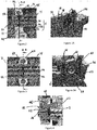
- La
figure 1 représente une vue en coupe longitudinale et de dessus d'un système de déphasage selon l'invention; - La
figure 2 représente une vue de détail de la zone référencée « II » sur lafigure 1 ; - La
figure 2A représente une vue en perspective selon la coupe A-A de lafigure 2 ; - La
figure 3 représente une vue de détail de la zone référencée « III » sur lafigure 1 ; - La
figure 3A représente une vue en perspective selon la coupe B-B de lafigure 3 ; - La
figure 4 représente une vue de détail de la zone référencée « IV » sur lafigure 1 . - En référence à la
figure 1 , un système de déphasage 1 selon l'invention comprend un arbre à cames 2 composé d'un conduit de lubrification 21 creux et d'un conduit d'huile de commande 22 d'un déphaseur 3. Le conduit de lubrification 21 et le conduit d'huile de commande 22 sont coaxiaux. - Le conduit de lubrification 21 est monté mobile en rotation par rapport à des paliers de guidage 4 fixés au moteur. Le conduit de lubrification 21 reçoit en outre six cames 8 espacées de manière régulière. Bien entendu, le nombre de cames 8 peut être différent dans d'autres modes de réalisation de l'invention.
- Dans cet exemple, le conduit de lubrification 21 est porté par trois paliers de guidage dont deux paliers d'extrémité 41, 42 et un palier intermédiaire 43. Le premier palier d'extrémité 41 est à gauche de la
figure 1 et le deuxième palier d'extrémité 42 est à droite de la même figure. - Le deuxième palier d'extrémité 42 porte un roulement à bille 45, d'où son nom de palier d'extrémité 42 à roulement. En revanche, le premier palier d'extrémité 41 ne comprend aucun roulement, d'où son nom de palier d'extrémité 41 lisse. Le palier intermédiaire 43 est situé à mi longueur de l'arbre à cames 2 pour empêcher la flexion de ce dernier. Bien entendu, le nombre de paliers intermédiaires peut être différent selon la structure de l'arbre à cames 2.
- Comme représenté à la
figure 1 , au niveau du palier d'extrémité 42 à roulement, le conduit de lubrification 21 coopère avec un déphaseur 3 hydraulique au moyen d'un embout 23. - Le déphaseur 3 comprend un conduit d'alimentation 31 qui s'étend suivant un axe de rotation R du rotor du déphaseur 3. A noter que l'axe de rotation R du déphaseur 3 est confondu avec l'axe de rotation de l'arbre à cames 2.
- Une vanne de distribution 32 est connectée à une extrémité du conduit d'alimentation 31. La distribution de l'huile sous pression dans le déphaseur 3 est contrôlée par un actionneur 7 et la vanne de distribution 32. L'actionneur comporte un doigt 71 mobile en translation selon l'axe de rotation R du déphaseur 3. Par son déplacement axial, le doigt 71 fait translater la vanne de distribution 32 et la mettre dans une position permettant le remplissage d'une chambre d'huile (non représentée) du déphaseur 3, ce qui permet d'actionner le rotor en rotation.
- La vanne de distribution 32 est vissée dans l'embout 23 d'une part et solidaire avec le rotor du déphaseur 3 d'autre part. Ainsi, lorsque le rotor tourne, il entraîne la vanne de distribution 32 et le conduit de lubrification 21 en rotation.
- Le palier d'extrémité 42 à roulement, le déphaseur 3, la vanne de distribution 32 et l'actionneur 7 sont situés au côté droit de la
figure 1 . La poulie de l'arbre à cames 2 se trouve également de ce côté. C'est pour cette raison que ce côté est également appelé côté de distribution. - Le palier d'extrémité 41 lisse est situé à l'autre côté de l'arbre à cames, à l'opposé du côté de distribution. De manière générale, ce côté opposé est adjacent à une boîte de vitesse (non représentée). On l'appelle ainsi le côté d'accouplement selon le vocabulaire utilisé par l'homme du métier.
- Le conduit de lubrification 21 délimite une chambre de lubrification 25 dans laquelle est logé le conduit d'huile de commande 22. Le conduit de lubrification 21 comprend en outre une extrémité 27 qui débouche dans le conduit d'alimentation 31 du déphaseur.
- Quant au conduit d'huile de commande 22, il délimite radialement un chambre d'huile centrale 24 qui débouche également dans le conduit d'alimentation 31 du déphaseur 3.
- Des orifices externes et internes sont réalisés respectivement au long du conduit de lubrification 22 et du conduit d'huile de commande 21.
- Un organe d'alimentation en huile sous pression 5 est positionné au niveau du palier d'extrémité 41 lisse pour fournir de l'huile au conduit d'huile de commande 22.
- L'organe d'alimentation en huile sous pression 5 est illustré de manière détaillée aux
figures 2 et 2A . Il relie un conduit d'amenée 53 au conduit d'huile de commande 22. Le conduit d'amenée 53 est intégré ici dans le palier d'extrémité 41 lisse. Le conduit d'amenée 53 débouche sur un orifice externe 51 percé dans la paroi du conduit de lubrification 21. Ce dernier comprend trois autres orifices externes (visibles à lafigure 2A ) qui sont espacés l'un de l'autre. De manière similaire, le conduit d'huile de commande 22 comprend quatre orifices internes 52 espacés l'un de l'autre. - Un bouchon 54 obture à la fois le conduit d'huile de commande 22 et le conduit de lubrification 24 au niveau du palier d'extrémité 41 lisse. Le bouchon 54 comprend en outre un passage 55 qui relie le conduit d'amenée 53 au conduit d'huile de commande 22. En d'autres termes, le passage 55 établit une connexion entre les orifices externes 51 et les orifices internes 52. Le passage 55 est ici une gorge 56 qui dessert de l'huile dans tous les orifices internes 52 comme cela est illustré par la flèche référencée « b » de la
figure 2A . - Par ailleurs, l'huile sous pression, par le chemin représenté par la flèche « a » de la
figure 2A , rentre aussi dans un espace e entre le palier d'extrémité 41 lisse et le conduit de lubrification 21 pour venir lubrifier la zone de contact et de frottement entre ces éléments. L'espace e est délimité par une rainure circonférentielle 26 pratiquée sur le conduit de lubrification 21 et une face interne du palier lisse 41. Les orifices externes 51 sont réalisés dans la rainure circonférentielle 26. - Le conduit d'huile de commande 22 comprend deux orifices secondaires 57 qui sont décalés vers la droite du palier d'extrémité 41 lisse. Ces orifices secondaires 57, diamétralement opposés, débouchent dans la chambre de lubrification 25. L'huile sous pression est ainsi amenée dans cette chambre de lubrification 25.
- Dans un autre exemple de réalisation, des passages reliant le conduit d'amenée 53 et la chambre de lubrification 25 sont réalisés sur le bouchon 54.
- En référence aux
figures 3 et 3A , le conduit d'huile de commande 22 comprend deux orifices internes intermédiaires 62. Ceux-ci, comme les orifices secondaires 57, sont diamétralement opposés et débouchent dans la chambre de lubrification 25. Parallèlement, le conduit de lubrification 21 comprend un orifice externe intermédiaire 61 débouchant dans la zone de contact e' entre le palier intermédiaire 43 et le conduit de lubrification 21. Ainsi, l'huile sous pression est conduit selon des flèches référencées « c » sur lafigure 3A pour venir lubrifier la zone de contact e' entre le palier intermédiaire 43 et le conduit de lubrification 21. - Sur la
figure 4 , la chambre d'huile centrale 24 débouchant dans le conduit d'alimentation 31, l'huile sous pression est conduite à l'intérieur du déphaseur 3 selon des flèches référencées « d ». L'arrivée de l'huile dans le déphaseur 3 est contrôlée par la vanne de distribution 32 et par l'actionneur 7 de manière à remplir la chambre à l'huile du déphaseur 3 afin de faire tourner l'arbre à cames 2. - Ainsi, grâce à l'organe d'alimentation 5 installé au niveau du palier d'extrémité 41 lisse, le déphaseur 3, situé au côté opposé, est alimenté en huile sous pression. En outre, l'huile sous pression est distribuée par le conduit de lubrification 25 vers les paliers lisses 41 et 43 pour permettre la lubrification des contacts.
- Il est à noter que le diamètre du conduit d'huile de commande 22, du conduit de lubrification 21 ainsi que la dimension des orifices internes 52, 62 et externes 51, 61 sont calibrés de manière à pouvoir maintenir une pression nécessaire de l'huile à l'intérieur du conduit d'huile de commande 22, ce qui permet un contrôle optimal du déphaseur. La pression d'huile dans le conduit d'huile de commande 22 est supérieure à la pression d'huile dans le conduit de lubrification 21.
Claims (10)
- Système de déphasage (1) pour moteur à combustion interne comprenant un arbre à cames (2) tenu par des paliers (4, 41, 42, 43) comportant un conduit de lubrification (21) des contacts entre l'arbre à cames (2) et les paliers (4, 41, 42, 43), ledit conduit de lubrification (21) comportant une extrémité (27) débouchant dans un déphaseur (3), ledit système de déphasage (1) étant caractérisé en ce que ledit conduit de lubrification (21) entoure un conduit coaxial d'huile de commande (22) d'un déphaseur (3) qui distribue dans le conduit de lubrification (21).
- Système de déphasage (1) selon la revendication 1 caractérisé en ce que la pression d'huile dans le conduit d'huile de commande (22) est supérieure à la pression d'huile dans le conduit de lubrification (21).
- Système de déphasage (1) selon la revendication 1 ou la revendication 2 caractérisé en ce qu'il comprend un organe d'alimentation (2) connecté avec un conduit d'amenée (53) d'huile et avec le conduit d'huile de commande (22).
- Système de déphasage (1) selon l'une des revendications 1 à 3 caractérisé en ce que le conduit de lubrification (21) délimite une chambre de lubrification (25) dans laquelle est logé le conduit d'huile de commande (22).
- Système de déphasage (1) selon l'une des revendications précédentes caractérisé en ce que le conduit d'huile de commande (22) comprend des orifices (57, 62) débouchant dans la chambre de lubrification (25).
- Système de déphasage (1) selon l'une des revendications précédentes caractérisé en ce que le système comprend un bouchon (54) obturant une extrémité du conduit de lubrification (21) et du conduit d'huile de commande (22), et comportant un passage (55) reliant le conduit d'amenée (53) au conduit d'huile de commande (22).
- Système de déphasage (1) selon la revendication 6 caractérisé en ce que le passage (55) s'étend autour du conduit d'huile de commande (22).
- Système de déphasage selon l'une des revendications 3 à 7 caractérisé en ce que le conduit de lubrification (21) comprend une rainure circonférentielle (25) au niveau du palier de guidage lisse (41), le conduit d'amenée (53) de l'huile sous pression débouchant dans ladite rainure circonférentielle (25).
- Moteur comprenant deux arbres à cames dont un premier coopère avec des soupapes d'admission et un deuxième coopère avec des soupapes d'échappement caractérisé en ce que chacun de ces arbres appartient à un système de déphasage (1) selon l'une des revendications précédentes.
- Véhicule automobile caractérisé en ce qu'il comprend un moteur selon la revendication 9.
Applications Claiming Priority (1)
| Application Number | Priority Date | Filing Date | Title |
|---|---|---|---|
| FR1662798A FR3060645B1 (fr) | 2016-12-19 | 2016-12-19 | Arbre a cames comportant un systeme de dephasage |
Publications (2)
| Publication Number | Publication Date |
|---|---|
| EP3336322A1 EP3336322A1 (fr) | 2018-06-20 |
| EP3336322B1 true EP3336322B1 (fr) | 2019-08-21 |
Family
ID=58455197
Family Applications (1)
| Application Number | Title | Priority Date | Filing Date |
|---|---|---|---|
| EP17200261.0A Active EP3336322B1 (fr) | 2016-12-19 | 2017-11-07 | Arbres à cames comportant un système de déphasage |
Country Status (2)
| Country | Link |
|---|---|
| EP (1) | EP3336322B1 (fr) |
| FR (1) | FR3060645B1 (fr) |
Family Cites Families (5)
| Publication number | Priority date | Publication date | Assignee | Title |
|---|---|---|---|---|
| JPS60173305A (ja) * | 1984-02-16 | 1985-09-06 | Honda Motor Co Ltd | 強制給油式カムシヤフト |
| DE4007181A1 (de) * | 1990-03-07 | 1991-09-12 | Audi Ag | Antriebsvorrichtung fuer eine nockenwelle |
| JP4036401B2 (ja) * | 1998-03-27 | 2008-01-23 | ヤマハ発動機株式会社 | 可変バルブタイミング装置を備えた4サイクルエンジン |
| JP4421166B2 (ja) * | 2002-01-10 | 2010-02-24 | 三菱自動車工業株式会社 | 仕切り壁を有する管及びその製造方法 |
| JP2009052527A (ja) * | 2007-08-29 | 2009-03-12 | Yamaha Motor Co Ltd | 4サイクル内燃機関及び車両 |
-
2016
- 2016-12-19 FR FR1662798A patent/FR3060645B1/fr not_active Expired - Fee Related
-
2017
- 2017-11-07 EP EP17200261.0A patent/EP3336322B1/fr active Active
Non-Patent Citations (1)
| Title |
|---|
| None * |
Also Published As
| Publication number | Publication date |
|---|---|
| FR3060645B1 (fr) | 2018-11-30 |
| EP3336322A1 (fr) | 2018-06-20 |
| FR3060645A1 (fr) | 2018-06-22 |
Similar Documents
| Publication | Publication Date | Title |
|---|---|---|
| CA2938385C (fr) | Turbomachine equipee d'un groupe de lubrification | |
| EP3710727B1 (fr) | Réducteur de vitesse a train planétaire ou épicycloïdal de turbomachine | |
| FR2977636A1 (fr) | Dispositif de lubrification d'un palier a roulement inter-arbres de turbopropulseur a double helice | |
| EP1728981A2 (fr) | Clapet à fuite controlée pour gicleur de refroidissement de piston | |
| CA2922034A1 (fr) | Ensemble rotatif comprenant un organe de transmission et un systeme de distribution d'huile | |
| EP0460988A1 (fr) | Dispositif de commande par arbre à came et moyens transmetteurs d'efforts à galet | |
| EP1891305A2 (fr) | Dispositif d'accouplement d'une pompe a vide avec un arbre a cames comprenant des moyens d'alimentation en fluide lubrifiant | |
| EP3336322B1 (fr) | Arbres à cames comportant un système de déphasage | |
| CA2492844C (fr) | Actionneur hydraulique de soupapes pour moteur a pistons | |
| EP3807508B1 (fr) | Porte-satellites tournant pour un reducteur mecanique d'une turbomachine | |
| EP3601747A1 (fr) | Relais d'accessoires pour moteur a turbine a gaz | |
| FR2987647A1 (fr) | Dispositif de filtre d'une soupape de commande d'un element de reglage d'arbre a came | |
| EP3289200B1 (fr) | Système de variation du taux de compression d'un moteur à combustion interne muni d'un élément de guidage de liquide lubrifiant | |
| EP3478945B1 (fr) | Lubrification du dos des cames par récupération d'huile | |
| FR3003300A1 (fr) | Systeme de transfert d'huile sur arbre tournant | |
| FR2744762A1 (fr) | Dispositif pour commander des soupapes d'un moteur a combustion interne | |
| EP3807507B1 (fr) | Dispositif de repartition d'huile pour un porte-satellites tournant d'un reducteur mecanique d'une turbomachine | |
| WO2019053371A1 (fr) | Pivot pour palier lisse | |
| FR3005129A1 (fr) | Dispositif de transfert d'un couple entre une machine electrique et un moteur thermique | |
| FR2950947A1 (fr) | Vanne destinee, notamment, a etre implantee dans un circuit d'admission d'air d'un moteur thermique | |
| EP2888510B1 (fr) | Gicleur de lubrification de chaine de distribution | |
| EP4180681A1 (fr) | Embrayage humide amélioré pour système de groupe motopropulseur | |
| FR3080650A1 (fr) | Ensemble de lubrification pour une turbomachine | |
| EP3818254A1 (fr) | Dispositif de commande d'un dephaseur d'arbre a cames | |
| FR3080147A1 (fr) | Vis de commande pour un dephaseur d'arbre a cames d'un moteur a combustion interne |
Legal Events
| Date | Code | Title | Description |
|---|---|---|---|
| PUAI | Public reference made under article 153(3) epc to a published international application that has entered the european phase |
Free format text: ORIGINAL CODE: 0009012 |
|
| STAA | Information on the status of an ep patent application or granted ep patent |
Free format text: STATUS: THE APPLICATION HAS BEEN PUBLISHED |
|
| AK | Designated contracting states |
Kind code of ref document: A1 Designated state(s): AL AT BE BG CH CY CZ DE DK EE ES FI FR GB GR HR HU IE IS IT LI LT LU LV MC MK MT NL NO PL PT RO RS SE SI SK SM TR |
|
| AX | Request for extension of the european patent |
Extension state: BA ME |
|
| STAA | Information on the status of an ep patent application or granted ep patent |
Free format text: STATUS: REQUEST FOR EXAMINATION WAS MADE |
|
| 17P | Request for examination filed |
Effective date: 20181210 |
|
| RBV | Designated contracting states (corrected) |
Designated state(s): AL AT BE BG CH CY CZ DE DK EE ES FI FR GB GR HR HU IE IS IT LI LT LU LV MC MK MT NL NO PL PT RO RS SE SI SK SM TR |
|
| GRAP | Despatch of communication of intention to grant a patent |
Free format text: ORIGINAL CODE: EPIDOSNIGR1 |
|
| RIC1 | Information provided on ipc code assigned before grant |
Ipc: F01M 9/10 20060101ALI20190206BHEP Ipc: F01L 1/344 20060101ALI20190206BHEP Ipc: F01L 1/047 20060101AFI20190206BHEP |
|
| STAA | Information on the status of an ep patent application or granted ep patent |
Free format text: STATUS: GRANT OF PATENT IS INTENDED |
|
| INTG | Intention to grant announced |
Effective date: 20190314 |
|
| GRAS | Grant fee paid |
Free format text: ORIGINAL CODE: EPIDOSNIGR3 |
|
| GRAA | (expected) grant |
Free format text: ORIGINAL CODE: 0009210 |
|
| STAA | Information on the status of an ep patent application or granted ep patent |
Free format text: STATUS: THE PATENT HAS BEEN GRANTED |
|
| AK | Designated contracting states |
Kind code of ref document: B1 Designated state(s): AL AT BE BG CH CY CZ DE DK EE ES FI FR GB GR HR HU IE IS IT LI LT LU LV MC MK MT NL NO PL PT RO RS SE SI SK SM TR |
|
| REG | Reference to a national code |
Ref country code: GB Ref legal event code: FG4D Free format text: NOT ENGLISH |
|
| REG | Reference to a national code |
Ref country code: CH Ref legal event code: EP |
|
| REG | Reference to a national code |
Ref country code: DE Ref legal event code: R096 Ref document number: 602017006332 Country of ref document: DE |
|
| REG | Reference to a national code |
Ref country code: AT Ref legal event code: REF Ref document number: 1169998 Country of ref document: AT Kind code of ref document: T Effective date: 20190915 |
|
| REG | Reference to a national code |
Ref country code: IE Ref legal event code: FG4D Free format text: LANGUAGE OF EP DOCUMENT: FRENCH |
|
| REG | Reference to a national code |
Ref country code: LT Ref legal event code: MG4D |
|
| REG | Reference to a national code |
Ref country code: NL Ref legal event code: MP Effective date: 20190821 |
|
| PG25 | Lapsed in a contracting state [announced via postgrant information from national office to epo] |
Ref country code: SE Free format text: LAPSE BECAUSE OF FAILURE TO SUBMIT A TRANSLATION OF THE DESCRIPTION OR TO PAY THE FEE WITHIN THE PRESCRIBED TIME-LIMIT Effective date: 20190821 Ref country code: NO Free format text: LAPSE BECAUSE OF FAILURE TO SUBMIT A TRANSLATION OF THE DESCRIPTION OR TO PAY THE FEE WITHIN THE PRESCRIBED TIME-LIMIT Effective date: 20191121 Ref country code: BG Free format text: LAPSE BECAUSE OF FAILURE TO SUBMIT A TRANSLATION OF THE DESCRIPTION OR TO PAY THE FEE WITHIN THE PRESCRIBED TIME-LIMIT Effective date: 20191121 Ref country code: NL Free format text: LAPSE BECAUSE OF FAILURE TO SUBMIT A TRANSLATION OF THE DESCRIPTION OR TO PAY THE FEE WITHIN THE PRESCRIBED TIME-LIMIT Effective date: 20190821 Ref country code: HR Free format text: LAPSE BECAUSE OF FAILURE TO SUBMIT A TRANSLATION OF THE DESCRIPTION OR TO PAY THE FEE WITHIN THE PRESCRIBED TIME-LIMIT Effective date: 20190821 Ref country code: PT Free format text: LAPSE BECAUSE OF FAILURE TO SUBMIT A TRANSLATION OF THE DESCRIPTION OR TO PAY THE FEE WITHIN THE PRESCRIBED TIME-LIMIT Effective date: 20191223 Ref country code: LT Free format text: LAPSE BECAUSE OF FAILURE TO SUBMIT A TRANSLATION OF THE DESCRIPTION OR TO PAY THE FEE WITHIN THE PRESCRIBED TIME-LIMIT Effective date: 20190821 Ref country code: FI Free format text: LAPSE BECAUSE OF FAILURE TO SUBMIT A TRANSLATION OF THE DESCRIPTION OR TO PAY THE FEE WITHIN THE PRESCRIBED TIME-LIMIT Effective date: 20190821 |
|
| PG25 | Lapsed in a contracting state [announced via postgrant information from national office to epo] |
Ref country code: LV Free format text: LAPSE BECAUSE OF FAILURE TO SUBMIT A TRANSLATION OF THE DESCRIPTION OR TO PAY THE FEE WITHIN THE PRESCRIBED TIME-LIMIT Effective date: 20190821 Ref country code: ES Free format text: LAPSE BECAUSE OF FAILURE TO SUBMIT A TRANSLATION OF THE DESCRIPTION OR TO PAY THE FEE WITHIN THE PRESCRIBED TIME-LIMIT Effective date: 20190821 Ref country code: IS Free format text: LAPSE BECAUSE OF FAILURE TO SUBMIT A TRANSLATION OF THE DESCRIPTION OR TO PAY THE FEE WITHIN THE PRESCRIBED TIME-LIMIT Effective date: 20191221 Ref country code: RS Free format text: LAPSE BECAUSE OF FAILURE TO SUBMIT A TRANSLATION OF THE DESCRIPTION OR TO PAY THE FEE WITHIN THE PRESCRIBED TIME-LIMIT Effective date: 20190821 Ref country code: GR Free format text: LAPSE BECAUSE OF FAILURE TO SUBMIT A TRANSLATION OF THE DESCRIPTION OR TO PAY THE FEE WITHIN THE PRESCRIBED TIME-LIMIT Effective date: 20191122 Ref country code: AL Free format text: LAPSE BECAUSE OF FAILURE TO SUBMIT A TRANSLATION OF THE DESCRIPTION OR TO PAY THE FEE WITHIN THE PRESCRIBED TIME-LIMIT Effective date: 20190821 |
|
| REG | Reference to a national code |
Ref country code: AT Ref legal event code: MK05 Ref document number: 1169998 Country of ref document: AT Kind code of ref document: T Effective date: 20190821 |
|
| PG25 | Lapsed in a contracting state [announced via postgrant information from national office to epo] |
Ref country code: TR Free format text: LAPSE BECAUSE OF FAILURE TO SUBMIT A TRANSLATION OF THE DESCRIPTION OR TO PAY THE FEE WITHIN THE PRESCRIBED TIME-LIMIT Effective date: 20190821 |
|
| PG25 | Lapsed in a contracting state [announced via postgrant information from national office to epo] |
Ref country code: DK Free format text: LAPSE BECAUSE OF FAILURE TO SUBMIT A TRANSLATION OF THE DESCRIPTION OR TO PAY THE FEE WITHIN THE PRESCRIBED TIME-LIMIT Effective date: 20190821 Ref country code: IT Free format text: LAPSE BECAUSE OF FAILURE TO SUBMIT A TRANSLATION OF THE DESCRIPTION OR TO PAY THE FEE WITHIN THE PRESCRIBED TIME-LIMIT Effective date: 20190821 Ref country code: AT Free format text: LAPSE BECAUSE OF FAILURE TO SUBMIT A TRANSLATION OF THE DESCRIPTION OR TO PAY THE FEE WITHIN THE PRESCRIBED TIME-LIMIT Effective date: 20190821 Ref country code: EE Free format text: LAPSE BECAUSE OF FAILURE TO SUBMIT A TRANSLATION OF THE DESCRIPTION OR TO PAY THE FEE WITHIN THE PRESCRIBED TIME-LIMIT Effective date: 20190821 Ref country code: RO Free format text: LAPSE BECAUSE OF FAILURE TO SUBMIT A TRANSLATION OF THE DESCRIPTION OR TO PAY THE FEE WITHIN THE PRESCRIBED TIME-LIMIT Effective date: 20190821 Ref country code: PL Free format text: LAPSE BECAUSE OF FAILURE TO SUBMIT A TRANSLATION OF THE DESCRIPTION OR TO PAY THE FEE WITHIN THE PRESCRIBED TIME-LIMIT Effective date: 20190821 |
|
| PG25 | Lapsed in a contracting state [announced via postgrant information from national office to epo] |
Ref country code: IS Free format text: LAPSE BECAUSE OF FAILURE TO SUBMIT A TRANSLATION OF THE DESCRIPTION OR TO PAY THE FEE WITHIN THE PRESCRIBED TIME-LIMIT Effective date: 20200224 Ref country code: SK Free format text: LAPSE BECAUSE OF FAILURE TO SUBMIT A TRANSLATION OF THE DESCRIPTION OR TO PAY THE FEE WITHIN THE PRESCRIBED TIME-LIMIT Effective date: 20190821 Ref country code: CZ Free format text: LAPSE BECAUSE OF FAILURE TO SUBMIT A TRANSLATION OF THE DESCRIPTION OR TO PAY THE FEE WITHIN THE PRESCRIBED TIME-LIMIT Effective date: 20190821 Ref country code: SM Free format text: LAPSE BECAUSE OF FAILURE TO SUBMIT A TRANSLATION OF THE DESCRIPTION OR TO PAY THE FEE WITHIN THE PRESCRIBED TIME-LIMIT Effective date: 20190821 |
|
| REG | Reference to a national code |
Ref country code: DE Ref legal event code: R097 Ref document number: 602017006332 Country of ref document: DE |
|
| PLBE | No opposition filed within time limit |
Free format text: ORIGINAL CODE: 0009261 |
|
| STAA | Information on the status of an ep patent application or granted ep patent |
Free format text: STATUS: NO OPPOSITION FILED WITHIN TIME LIMIT |
|
| PG2D | Information on lapse in contracting state deleted |
Ref country code: IS |
|
| PG25 | Lapsed in a contracting state [announced via postgrant information from national office to epo] |
Ref country code: LU Free format text: LAPSE BECAUSE OF NON-PAYMENT OF DUE FEES Effective date: 20191107 Ref country code: MC Free format text: LAPSE BECAUSE OF FAILURE TO SUBMIT A TRANSLATION OF THE DESCRIPTION OR TO PAY THE FEE WITHIN THE PRESCRIBED TIME-LIMIT Effective date: 20190821 |
|
| 26N | No opposition filed |
Effective date: 20200603 |
|
| REG | Reference to a national code |
Ref country code: BE Ref legal event code: MM Effective date: 20191130 |
|
| PG25 | Lapsed in a contracting state [announced via postgrant information from national office to epo] |
Ref country code: SI Free format text: LAPSE BECAUSE OF FAILURE TO SUBMIT A TRANSLATION OF THE DESCRIPTION OR TO PAY THE FEE WITHIN THE PRESCRIBED TIME-LIMIT Effective date: 20190821 |
|
| PG25 | Lapsed in a contracting state [announced via postgrant information from national office to epo] |
Ref country code: IE Free format text: LAPSE BECAUSE OF NON-PAYMENT OF DUE FEES Effective date: 20191107 |
|
| PG25 | Lapsed in a contracting state [announced via postgrant information from national office to epo] |
Ref country code: BE Free format text: LAPSE BECAUSE OF NON-PAYMENT OF DUE FEES Effective date: 20191130 |
|
| PG25 | Lapsed in a contracting state [announced via postgrant information from national office to epo] |
Ref country code: CY Free format text: LAPSE BECAUSE OF FAILURE TO SUBMIT A TRANSLATION OF THE DESCRIPTION OR TO PAY THE FEE WITHIN THE PRESCRIBED TIME-LIMIT Effective date: 20190821 |
|
| PG25 | Lapsed in a contracting state [announced via postgrant information from national office to epo] |
Ref country code: CH Free format text: LAPSE BECAUSE OF FAILURE TO SUBMIT A TRANSLATION OF THE DESCRIPTION OR TO PAY THE FEE WITHIN THE PRESCRIBED TIME-LIMIT Effective date: 20201130 Ref country code: LI Free format text: LAPSE BECAUSE OF FAILURE TO SUBMIT A TRANSLATION OF THE DESCRIPTION OR TO PAY THE FEE WITHIN THE PRESCRIBED TIME-LIMIT Effective date: 20201130 |
|
| REG | Reference to a national code |
Ref country code: CH Ref legal event code: PL |
|
| PG25 | Lapsed in a contracting state [announced via postgrant information from national office to epo] |
Ref country code: HU Free format text: LAPSE BECAUSE OF FAILURE TO SUBMIT A TRANSLATION OF THE DESCRIPTION OR TO PAY THE FEE WITHIN THE PRESCRIBED TIME-LIMIT; INVALID AB INITIO Effective date: 20171107 Ref country code: MT Free format text: LAPSE BECAUSE OF FAILURE TO SUBMIT A TRANSLATION OF THE DESCRIPTION OR TO PAY THE FEE WITHIN THE PRESCRIBED TIME-LIMIT Effective date: 20190821 |
|
| PG25 | Lapsed in a contracting state [announced via postgrant information from national office to epo] |
Ref country code: MK Free format text: LAPSE BECAUSE OF FAILURE TO SUBMIT A TRANSLATION OF THE DESCRIPTION OR TO PAY THE FEE WITHIN THE PRESCRIBED TIME-LIMIT Effective date: 20190821 |
|
| GBPC | Gb: european patent ceased through non-payment of renewal fee |
Effective date: 20211107 |
|
| PG25 | Lapsed in a contracting state [announced via postgrant information from national office to epo] |
Ref country code: GB Free format text: LAPSE BECAUSE OF NON-PAYMENT OF DUE FEES Effective date: 20211107 |
|
| P01 | Opt-out of the competence of the unified patent court (upc) registered |
Effective date: 20230608 |
|
| PGFP | Annual fee paid to national office [announced via postgrant information from national office to epo] |
Ref country code: FR Payment date: 20231120 Year of fee payment: 7 Ref country code: DE Payment date: 20231121 Year of fee payment: 7 |