EP3336313A1 - Turbine rotor blade arrangement for a gas turbine and method for the provision of sealing air in a turbine rotor blade arrangement - Google Patents
Turbine rotor blade arrangement for a gas turbine and method for the provision of sealing air in a turbine rotor blade arrangement Download PDFInfo
- Publication number
- EP3336313A1 EP3336313A1 EP17208073.1A EP17208073A EP3336313A1 EP 3336313 A1 EP3336313 A1 EP 3336313A1 EP 17208073 A EP17208073 A EP 17208073A EP 3336313 A1 EP3336313 A1 EP 3336313A1
- Authority
- EP
- European Patent Office
- Prior art keywords
- air
- turbine
- channel
- blade root
- deflection device
- Prior art date
- Legal status (The legal status is an assumption and is not a legal conclusion. Google has not performed a legal analysis and makes no representation as to the accuracy of the status listed.)
- Withdrawn
Links
Images


Classifications
-
- F—MECHANICAL ENGINEERING; LIGHTING; HEATING; WEAPONS; BLASTING
- F01—MACHINES OR ENGINES IN GENERAL; ENGINE PLANTS IN GENERAL; STEAM ENGINES
- F01D—NON-POSITIVE DISPLACEMENT MACHINES OR ENGINES, e.g. STEAM TURBINES
- F01D5/00—Blades; Blade-carrying members; Heating, heat-insulating, cooling or antivibration means on the blades or the members
- F01D5/12—Blades
- F01D5/14—Form or construction
- F01D5/18—Hollow blades, i.e. blades with cooling or heating channels or cavities; Heating, heat-insulating or cooling means on blades
- F01D5/187—Convection cooling
-
- F—MECHANICAL ENGINEERING; LIGHTING; HEATING; WEAPONS; BLASTING
- F01—MACHINES OR ENGINES IN GENERAL; ENGINE PLANTS IN GENERAL; STEAM ENGINES
- F01D—NON-POSITIVE DISPLACEMENT MACHINES OR ENGINES, e.g. STEAM TURBINES
- F01D11/00—Preventing or minimising internal leakage of working-fluid, e.g. between stages
- F01D11/005—Sealing means between non relatively rotating elements
- F01D11/006—Sealing the gap between rotor blades or blades and rotor
-
- F—MECHANICAL ENGINEERING; LIGHTING; HEATING; WEAPONS; BLASTING
- F01—MACHINES OR ENGINES IN GENERAL; ENGINE PLANTS IN GENERAL; STEAM ENGINES
- F01D—NON-POSITIVE DISPLACEMENT MACHINES OR ENGINES, e.g. STEAM TURBINES
- F01D11/00—Preventing or minimising internal leakage of working-fluid, e.g. between stages
- F01D11/02—Preventing or minimising internal leakage of working-fluid, e.g. between stages by non-contact sealings, e.g. of labyrinth type
- F01D11/04—Preventing or minimising internal leakage of working-fluid, e.g. between stages by non-contact sealings, e.g. of labyrinth type using sealing fluid, e.g. steam
-
- F—MECHANICAL ENGINEERING; LIGHTING; HEATING; WEAPONS; BLASTING
- F01—MACHINES OR ENGINES IN GENERAL; ENGINE PLANTS IN GENERAL; STEAM ENGINES
- F01D—NON-POSITIVE DISPLACEMENT MACHINES OR ENGINES, e.g. STEAM TURBINES
- F01D5/00—Blades; Blade-carrying members; Heating, heat-insulating, cooling or antivibration means on the blades or the members
- F01D5/02—Blade-carrying members, e.g. rotors
- F01D5/08—Heating, heat-insulating or cooling means
- F01D5/085—Heating, heat-insulating or cooling means cooling fluid circulating inside the rotor
- F01D5/087—Heating, heat-insulating or cooling means cooling fluid circulating inside the rotor in the radial passages of the rotor disc
-
- F—MECHANICAL ENGINEERING; LIGHTING; HEATING; WEAPONS; BLASTING
- F01—MACHINES OR ENGINES IN GENERAL; ENGINE PLANTS IN GENERAL; STEAM ENGINES
- F01D—NON-POSITIVE DISPLACEMENT MACHINES OR ENGINES, e.g. STEAM TURBINES
- F01D5/00—Blades; Blade-carrying members; Heating, heat-insulating, cooling or antivibration means on the blades or the members
- F01D5/12—Blades
- F01D5/14—Form or construction
- F01D5/18—Hollow blades, i.e. blades with cooling or heating channels or cavities; Heating, heat-insulating or cooling means on blades
-
- F—MECHANICAL ENGINEERING; LIGHTING; HEATING; WEAPONS; BLASTING
- F01—MACHINES OR ENGINES IN GENERAL; ENGINE PLANTS IN GENERAL; STEAM ENGINES
- F01D—NON-POSITIVE DISPLACEMENT MACHINES OR ENGINES, e.g. STEAM TURBINES
- F01D11/00—Preventing or minimising internal leakage of working-fluid, e.g. between stages
- F01D11/001—Preventing or minimising internal leakage of working-fluid, e.g. between stages for sealing space between stator blade and rotor
-
- F—MECHANICAL ENGINEERING; LIGHTING; HEATING; WEAPONS; BLASTING
- F01—MACHINES OR ENGINES IN GENERAL; ENGINE PLANTS IN GENERAL; STEAM ENGINES
- F01D—NON-POSITIVE DISPLACEMENT MACHINES OR ENGINES, e.g. STEAM TURBINES
- F01D5/00—Blades; Blade-carrying members; Heating, heat-insulating, cooling or antivibration means on the blades or the members
- F01D5/30—Fixing blades to rotors; Blade roots ; Blade spacers
- F01D5/3007—Fixing blades to rotors; Blade roots ; Blade spacers of axial insertion type
-
- F—MECHANICAL ENGINEERING; LIGHTING; HEATING; WEAPONS; BLASTING
- F05—INDEXING SCHEMES RELATING TO ENGINES OR PUMPS IN VARIOUS SUBCLASSES OF CLASSES F01-F04
- F05D—INDEXING SCHEME FOR ASPECTS RELATING TO NON-POSITIVE-DISPLACEMENT MACHINES OR ENGINES, GAS-TURBINES OR JET-PROPULSION PLANTS
- F05D2220/00—Application
- F05D2220/30—Application in turbines
- F05D2220/32—Application in turbines in gas turbines
-
- F—MECHANICAL ENGINEERING; LIGHTING; HEATING; WEAPONS; BLASTING
- F05—INDEXING SCHEMES RELATING TO ENGINES OR PUMPS IN VARIOUS SUBCLASSES OF CLASSES F01-F04
- F05D—INDEXING SCHEME FOR ASPECTS RELATING TO NON-POSITIVE-DISPLACEMENT MACHINES OR ENGINES, GAS-TURBINES OR JET-PROPULSION PLANTS
- F05D2240/00—Components
- F05D2240/20—Rotors
- F05D2240/30—Characteristics of rotor blades, i.e. of any element transforming dynamic fluid energy to or from rotational energy and being attached to a rotor
- F05D2240/301—Cross-sectional characteristics
-
- F—MECHANICAL ENGINEERING; LIGHTING; HEATING; WEAPONS; BLASTING
- F05—INDEXING SCHEMES RELATING TO ENGINES OR PUMPS IN VARIOUS SUBCLASSES OF CLASSES F01-F04
- F05D—INDEXING SCHEME FOR ASPECTS RELATING TO NON-POSITIVE-DISPLACEMENT MACHINES OR ENGINES, GAS-TURBINES OR JET-PROPULSION PLANTS
- F05D2240/00—Components
- F05D2240/55—Seals
-
- F—MECHANICAL ENGINEERING; LIGHTING; HEATING; WEAPONS; BLASTING
- F05—INDEXING SCHEMES RELATING TO ENGINES OR PUMPS IN VARIOUS SUBCLASSES OF CLASSES F01-F04
- F05D—INDEXING SCHEME FOR ASPECTS RELATING TO NON-POSITIVE-DISPLACEMENT MACHINES OR ENGINES, GAS-TURBINES OR JET-PROPULSION PLANTS
- F05D2240/00—Components
- F05D2240/80—Platforms for stationary or moving blades
- F05D2240/81—Cooled platforms
-
- F—MECHANICAL ENGINEERING; LIGHTING; HEATING; WEAPONS; BLASTING
- F05—INDEXING SCHEMES RELATING TO ENGINES OR PUMPS IN VARIOUS SUBCLASSES OF CLASSES F01-F04
- F05D—INDEXING SCHEME FOR ASPECTS RELATING TO NON-POSITIVE-DISPLACEMENT MACHINES OR ENGINES, GAS-TURBINES OR JET-PROPULSION PLANTS
- F05D2260/00—Function
- F05D2260/20—Heat transfer, e.g. cooling
- F05D2260/201—Heat transfer, e.g. cooling by impingement of a fluid
Definitions
- the invention relates to a turbine blade assembly according to the preamble of claim 1 and a method for providing sealing air in a turbine blade assembly.
- the present invention is based on the object to provide a turbine blade assembly and a method for providing sealing air, the air ducts, which are formed in the blade root or between the blade root and Schaufelfuß technique safely protect against hot air.
- the present invention is based on a turbine blade assembly including a turbine disk and a turbine blade ring.
- the turbine disk is rotatable about a machine axis of the gas turbine and has a plurality of Schaufelfußfactn on its periphery.
- the turbine blade ring comprises a plurality of blades each comprising a blade root and secured to the periphery of the turbine disk by locating the blade roots in the blade root seats.
- the turbine disk includes disk passages which serve to provide air and which run with a radial directional component.
- a disc channel ends in each case in the region of a Schaufelfuß technique in an outlet opening.
- the blades have cooling air channels for cooling the blades.
- the disc channels of the turbine disc and the cooling air channels of the Blades are designed and arranged such that during operation, air is supplied via the disk channels of the turbine disk to the cooling air passages of the rotor blades.
- the air emerging from a disk channel in this case has a radial direction component.
- the blades of the turbine blade assembly under consideration further comprise at least one air passage in the blade root or between the blade root and the blade root receiver, via which sealing air which is fed from the pulley channel emerges. Over the air duct sealing air, which emerges from the disc channel, led away from the blade root.
- the present invention provides that the blade root has a deflection device, which is provided and designed to redirect part of the air emerging from the disk channel, in the direction of the air duct.
- a deflection device which is provided and designed to redirect part of the air emerging from the disk channel, in the direction of the air duct.
- the present invention is based on the finding that by providing a deflection device arranged in or on the blade root, the dynamic pressure of the air flow is maintained, which leads to an increase in the total pressure.
- Such an increase in pressure is associated with several advantages.
- a first advantage is that due to the increased pressure, the risk is banned that flow under unfavorable operating conditions hot gas from the main flow channel through the air duct into the blade or a flow reversal takes place in the air duct. The risk of damage to the blades by hot gas is eliminated.
- the sealing air which flows with increased total pressure ratio across the air duct, can be used to reliably fulfill other functions in the gas turbine.
- a function is, for example, to use the air flowing out of the air duct to the seal.
- it may be provided to apply to this air seals, which are formed in the edge region of the main flow channel of the gas turbine between the rotating turbine blade assembly and adjacent, non-rotating structures, in particular an adjacent turbine vane ring (so-called "rim seals" or Radreteraumdichtepteptept.
- rim seals or Radreteraumdicht Institute
- the concept of a microturbine is in the EP 1 004 748 B1 described, to which reference is made.
- Another advantage associated with the invention is that, due to the increase of the total pressure in the air duct provided by the deflection device, the diameter of the disk channels formed in the turbine disk can be reduced. Because a sufficient pressure build-up can be provided due to the invention even with comparatively small pulley channels. By reducing the diameter, without the present invention, the pressure loss (loss of expansion) increases as it transitions into the cavity within the blade root. This can be compensated by the invention, which allows a reduction of the disk channel diameter, thereby reducing stress peaks and thus increasing the stability of the turbine disk.
- the gap which extends in the axial direction between the blade root receiver and the blade root arranged therein.
- the deflection device is arranged on the underside of the blade root. Air emerging from the outlet opening of the disk channel is thus deflected by means of the deflecting device on the underside of the blade root and transported in the air channel formed by the gap between the blade root and blade receptacle with sufficient dynamic pressure.
- the air channel may be formed in other ways than through the gap between the blade root and blade receptacle.
- the blade root forms a cavity into which flows at least part of the air before it is passed as cooling air into the cooling air channels of the blade.
- the orientation of the flow in the air duct can be adjusted via the radial distance of the opening from the underside of the blade root and its orientation.
- the deflection device partially covers the outlet opening of the disk channel.
- overlap refers to a view from above (opposite to the radial direction) on the outlet opening.
- the deflection device partially cover the outlet opening of the window channel.
- the deflection device is detected by the emerging from the disc channel air. This is in addition to the case of the overlap also the case when the exiting the disc channel airflow is divergent and due to its expansion partially flows against the deflection device. It is true that the emerging from the disc channel airflow widens with increasing distance from the outlet opening.
- An embodiment of the invention provides that the deflection device is arranged and designed such that air is deflected from the disk channel in the direction of the leading edge of the blade root in the air channel.
- the deflection is thus upstream relative to the flow direction in the main flow channel.
- sealing air in the direction of the trailing edge of the blade root, i. downstream of the flow direction in the main flow channel of the gas turbine is deflected into the air duct.
- the sealing air is used, for example, to cool or seal components which are arranged in the axial direction behind the turbine blade assembly.
- the blade has a plurality of deflection devices, which redirect the sealing air into different air ducts and, for example, make a diversion on the one hand in the direction of the leading edge and on the other in the direction of the trailing edge of the blade root.
- a further embodiment of the invention provides that the deflection device forms the initial region of the respective air channel. It forms the radially outer boundary of the air duct and goes smoothly into the air duct.
- the air duct begins only at a distance from the deflection device, in which case the Deflector directs air in the direction of the air duct without already being part of the air duct.
- the deflection device can basically have a multiplicity of geometric shapes and structural configurations.
- the deflection device form a flat surface, is deflected at the air.
- the deflection device is a planar sheet metal which partially covers the outlet opening of the disk channel and thereby directs air emerging from the disk channel into the air channel and thereby increases the total pressure ratio via the passage.
- the deflection device is a planar sheet metal which partially covers the outlet opening of the disk channel and thereby directs air emerging from the disk channel into the air channel and thereby increases the total pressure ratio via the passage.
- this simplest embodiment of the occurring on the flat surface dynamic pressure loss is relatively large, whereby a comparatively low effect is achieved.
- the deflection device at least in the region which is detected by the air emerging from the disk channel, forms a concave surface which runs concavely to the disk channel or to the air flow exiting therefrom. It can be provided that the concave surface smoothly merges into the air duct.
- the design of the deflection device with a surface that is concave toward the disk channel makes it possible to deflect the airflow emerging from the disk channel with little loss into the air channel, avoiding perpendicularly to the flow direction arranged impact body. As a result, a large part of the dynamic pressure can be recovered and thus the driving pressure ratio can be increased significantly over the air duct.
- the deflecting device partially covers the outlet opening of the disk channel, according to one embodiment the deflecting device forms a concave surface, at least in the area partially covering the outlet opening of the disk channel, which runs concave to the disk channel or to the air flow exiting therefrom.
- a deflection device and an air duct can be provided which realize widths and radii of curvature such that the relationship r_m / w> 1 is satisfied, where w is the mean Width of the air duct in the region of the deflecting device and r_m is the average of a first, outer radius of curvature r_o and a second, inner radius of curvature r_i, wherein the first radius of curvature r_o the radius of curvature of the concave surface of the deflecting device and the second radius of curvature r_i the radius in the transition from the Disc channel to the leading edge of Schaufelfuß technique represents.
- the deflection device is formed by a nose-shaped component. Its end faces the disc channel or the outlet opening. It can be provided that the end of the nose-shaped component partially covers the outlet opening of the disk channel. "Nose-shaped” here means that the nose-shaped component in the circumferential direction of the turbine disk is not or only slightly wider than the outlet opening of the disk channel.
- a further embodiment provides that the deflection device in a view from above onto the outlet opening (i.e., on a plane normal to the radial direction) partially covers it along a straight boundary line.
- this boundary line is concave or convex to the outlet opening formed.
- the boundary line can be formed, for example, circular, elliptical, parabolic or hyperbolic.
- the overlap of the outlet opening of the disk channel in a view from above on the outlet opening is at least 10% of the total cross-sectional area of the outlet opening.
- the coverage may be in the range between 10% and 25%, in particular in the range between 15% and 20% of the total cross-sectional area of the outlet opening.
- the degree of overlap is to be optimized so that on the one hand provided a sufficient total pressure in the air duct and on the other hand, the cooling air supply of the blade channels and thus the cooling of the blades is not affected.
- the air duct is aligned in its end portion, ie in the portion which adjoins the opening of the air duct in the region of the leading edge or trailing edge of the blade root, at an angle to the axial direction of the gas turbine. This ensures that sealing air is directed at an angle into the cavity adjacent to the blade. The flow of work is taken, whereby the blades are additionally accelerated. It can be provided that the air ducts are formed toward their output as a nozzle. Such an embodiment is also referred to as a microturbine and is in the EP 1 004 748 B1 described in detail.
- the deflection device may be an integral part of the blade root. For example, it is realized by a component which is produced together with the blade root as a casting or by machining processes. Alternatively, the deflection device may be a separately manufactured component that is connected to the underside of the blade root after production of the blade root. In this embodiment, the deflection device can be provided as a retrofit device for already manufactured turbine blade assemblies. For example, a flat or curved plate is attached to the underside of the blade root in such a way that it partially covers the outlet opening of the disk channel.
- the deflection device is a continuous or continuous component insofar as it has no holes or perforations for a flow of air.
- the present invention also relates to a method for providing sealing air in a turbine blade assembly comprising a turbine disk and a turbine blade ring, wherein air is supplied via disk disks formed in the turbine disk, each ending in the area of a blade root receiver in an exhaust port, and in Cooling air channels of the blades of the turbine blade ring is blown. It is envisaged that emerging from the disc channel air is deflected by means of a deflecting device partially in the direction of an air duct over which the air is passed as sealing air away from the blade root. It can be provided that the deflection device partially covers the outlet opening of the disk channel. If the air leaving the disc channel is divergent, this is not necessarily the case.
- FIG. 1 1 schematically shows a turbofan engine 100 having a fan stage with a fan 10 as a low-pressure compressor, a medium-pressure compressor 20, a high-pressure compressor 30, a combustion chamber 40, a high-pressure turbine 50, a medium-pressure turbine 60 and a low-pressure turbine 70.
- the medium-pressure compressor 20 and the high-pressure compressor 30 each have a plurality of compressor stages, each comprising a rotor stage and a stator stage.
- the turbofan engine 100 of FIG. 1 further comprises three separate shafts, a low pressure shaft 81 connecting the low pressure turbine 70 to the fan 10, a medium pressure shaft 82 connecting the medium pressure turbine 60 to the intermediate pressure compressor 20, and a high pressure shaft 83 connecting the high pressure turbine 50 to the high pressure compressor 30.
- this is only to be understood as an example.
- the turbofan engine did not have a medium pressure compressor and medium pressure turbine, only a low pressure shaft and a high pressure shaft would be present.
- the turbofan engine 100 has an engine nacelle 1, which comprises an inlet lip 14 and, on the inside, forms an engine inlet 11, which supplies incoming air to the fan 10.
- the fan 10 has a plurality of fan blades 101 connected to a fan disk 102.
- the annulus of the fan disk 102 forms the radially inner boundary of the flow path through the fan 10. Radially outside the flow path is limited by a fan housing 2. Upstream of the fan disk 102, a nose cone 103 is disposed.
- the turbofan engine 100 forms a secondary flow channel 4 and a primary flow channel 5.
- the primary flow channel 5 passes through the core engine (gas turbine) comprising the medium pressure compressor 20, the high pressure compressor 30, the combustor 40, the high pressure turbine 50, the medium pressure turbine 60, and the low pressure turbine 70.
- the medium-pressure compressor 20 and the high-pressure compressor 30 are surrounded by a peripheral housing 29 that inside a Annular space surface which defines the primary flow channel 5 radially outward.
- Radially inside, the primary flow channel 5 is bounded by corresponding ring surfaces of the rotors and stators of the respective compressor stages or by the hub or hub connected to the elements of the corresponding drive shaft.
- a primary flow passes through the primary flow passage 5, which is also referred to as the main flow passage.
- the secondary flow channel 4 also referred to as bypass duct, bypass duct or bypass duct, passes in the operation of the turbofan engine 100 by the fan 10 sucked air past the core engine.
- the described components have a common axis of rotation 90.
- the axis of rotation 90 defines an axial direction of the turbofan engine.
- a radial direction of the turbofan engine is perpendicular to the axial direction.
- the design of the blade assembly, in particular the first stage of the high-pressure turbine 50 is important.
- the principles of the present invention are equally applicable to blade assemblies of other turbine stages.
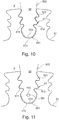
- FIG. 2 shows schematically in sectional view a turbine blade assembly, as known from the prior art.
- the FIG. 10 shows such an arrangement in a front view.
- x indicate the axial direction and r the radial direction.
- the circumferential direction is perpendicular to x and r.
- the axial direction x may be identical to the machine axis of a gas turbine engine in which the invention is implemented, but may be different (if the blades are inserted into the blade root receivers at an angle to the machine axis).
- the blade assembly includes a turbine disk 51 and a turbine blade ring with blades 52.
- the blades 52 each include a blade root 521 and an airfoil 522 that projects into a main flow channel 5 of the gas turbine engine. Via hot gases in the main flow channel 5, which transfer energy to the blades 522, the blade ring and the turbine disk 51 are set in rotation, wherein the turbine disk 51 about the machine axis of the gas turbine (see FIG. 1 ) and drives a drive shaft.
- the turbine disk 51 For attachment of the rotor blades 52 at an equidistant distance on the circumference of the turbine disk 51, the turbine disk 51 has at its periphery a plurality of blade root receivers 57, which each serve to receive a blade root 521 of a rotor blade 51. It is provided, for example, that the blade roots 521 are designed as so-called "pine tree feet" which ensure a distribution of the centripetal force absorption under centrifugal force loading.
- the Schaufelfußing techniquen 57 are formed in a corresponding manner.
- the Schaufelfuß techniquen 57 include, in particular in the FIG. 10 a bottom wall 510 and two circumferentially spaced sidewalls 511, 512 which are structured to hold the blade roots 521 in a positive fit.
- the turbine disk 51 has disk channels 53 which serve to provide cooling air for cooling the rotor blades 52.
- the disk channels 53 each end in the region of a blade root receiver 57, namely in the bottom wall 510, where they form an outlet opening 530.
- the blades 52 include cooling air channels 54 that serve to cool the blades 52.
- the exact shape of the cooling air channels 54 and the type of cooling are not important to the present invention. There is, for example, a film cooling and / or cooling by convection.
- the cooling air ducts 54 start from a cavity 56, which is formed in the blade root 521. From the pulley channels 53 exiting cooling air 531 is passed through the cavity 56 in the cooling air channels 54.
- the blade root 521 and the blade receptacle two gaps 551, 552 are formed, each extending between the bottom 523 of the blade root 521 and the Schaufelfußfact.
- the one gap 551 extends from the cavity 56 in the direction of the leading edge of the blade root 521 and the other gap 552 from the cavity 56 in the direction of the trailing edge of the blade root 521.
- the gap 551 can be seen, which extends in the direction of the front edge of the blade root 521.
- the turbine blade assembly is disposed in the axial direction between non-rotating structures 6, 8 of the gas turbine.
- a static structure 6 is located in the axial direction in front of the turbine blade arrangement.
- the blade arrangement and the static structure 6, for example a vane arrangement or an adjoining part, are in this case through a cavity 71 which extends in the radial direction extends, separated from each other.
- a seal 61 which is adjacent to the main flow channel 5 (so-called "rim seal" is provided. If hot gases penetrate through the seal 61 in the cavity 71, there is a risk that such hot gases damage the turbine disk.
- a sealing mass flow is controlled by a second seal 62 and the leakage or sealing air through the gap between the blade root 521 and Schaufelfußability.
- the cooling air is guided through swirl nozzles 63 into the annular space or the cavity 71.
- the cooling air changes from the housing-fixed system into the rotating relative system.
- the cooling air then flows further into the cooling air holes 53 of the turbine disk 51.
- the use of swirl nozzles 63 is merely optional.
- a non-rotating structure 8 for example a further vane arrangement, is located in the axial direction behind the turbine blade arrangement, wherein the rotor blade arrangement and the structure 8 are separated from each other by a cavity 72.
- FIG. 3 shows a first embodiment of a turbine blade assembly 50 according to the present invention.
- a deflection device 31 is provided which partially covers the outlet opening 530 of the window channel 53, ie partially projects beyond it.
- the deflecting device 51 is provided for this purpose and designed cooling air 531, which emerges from the outlet opening 530, partially divert in the direction of an air passage 551 to increase the driving pressure ratio on this, as shown by the arrow 532.
- the air channel 551 is formed in the considered embodiment by the gap which is formed between the underside 523 of the blade root 521 and the Schaufelfußability, in particular the bottom wall 510 and thereby extends in the axial direction in the direction of the leading edge of the blade root 521.
- a deflection device may also be arranged in such a way that it deflects cooling air in the direction of an air channel 552, which extends in the direction of the trailing edge of the blade root 521.
- the illustrated embodiment is only to be understood as an example.
- the deflecting device 31 is concave on its underside 310, which faces the outlet opening 530 of the disk channel 53, with respect to the outlet opening 530. As a result, it absorbs part of the cooling air without great pressure loss and transfers it in a low-loss manner in the direction of the air duct 551 so as to increase the driving pressure ratio. From the air channel 551, the cooling air enters the cavity 71 a. Due to the targeted deflection of a portion of the air by means of the deflection device 31 is in the cooling air passage 551 a compared with that in the FIG. 2 situation presented increased pressure. This increased pressure prevents a potential return flow through the air duct 551 and thus ensures a more reliable supply of the seal 61. This prevents the risk of hot gas entering the cavity 71.
- sealing air provided via the air channel 551. It can be provided as explained that the sealing air according to the arrow 534 of FIG. 3 is used to pressurize the seal 61 with sealing air and thereby prevent hot gases from the main flow channel 5, the seal 61 can pass. If such a function is provided via the compressed air of the cooling air passage 551, the further seal 62 can be simplified.
- Another embodiment provides that the sealing air from the air duct 551 is injected obliquely into the cavity 71.
- the air duct 551 is aligned obliquely to the axial direction, at least in the section which adjoins the cavity 71.
- the oblique blowing of the cooling air into the cavity leads to an additional acceleration of the blades and to a reduction in the temperature of the cooling air.
- the exact relationships can be described by the Euler equations.
- sealing air is provided in a corresponding manner in the rearwardly extending air duct 552, for example to supply subsequent rows of blades with compressed air, this air can also be used for cooling purposes, such as. a blade cooling.
- FIG. 4 shows an embodiment of a turbine blade assembly 50, wherein the air duct, is deflected in the deflected by the deflection device 31 air, not through the gap 551 between the blade root and Schaufelfuß technique, but by an additional passage.
- a further air channel 553 is provided. This runs at a radial distance to the bottom 523 of the blade root 521 and ends in an outlet opening 554.
- the deflection device 31 is arranged deeper in the cavity 56 of the blade root 521 in this embodiment.
- the position and orientation of the outlet opening 554 can be used to align the sealing air flow emerging from the air duct 553.
- FIG. 11 shows the arrangement of FIG. 4 in a view from the front.
- the representation largely corresponds to the representation of FIG. 10 ,
- the air channel 553 is shown, which ends in an outlet opening 554.
- FIG. 4A shows a modification of the embodiment of FIG. 4
- FIG. 4B shows an enlarged view of the area of the deflection of the FIG. 4A
- the air duct in which air is deflected by the deflection device, is not formed by the gap 551 between the blade root and the blade root receiver, but by an additional passage 553, which extends at a radial distance to the underside 523 of the blade root 521 and ends in an outlet opening 554.
- FIG. 4 The difference to the embodiment of FIG. 4 exists in the position of the deflection device. While in the FIG. 4 the deflection device, the outlet opening 530 of the disc channel 53 partially covered, this is in the FIGS. 4A . 4B not the case.
- a deflection device 45 is provided, which does not cover the outlet opening 530, but which is still detected by the divergent emerging from the disc channel 53 air, as shown by the schematically illustrated flow paths of the cooling air 531.
- the cooling air facing surface 450 of the deflecting device 45 is concave. In doing so, it continuously merges into the radially outer boundary wall of the air duct 553. Just like in the FIG.
- the deflection device 45 is disposed relatively deep in the cavity 56 of the blade root 521. The deeper the arrangement in the cavity 56, the more likely the deflecting device 45, despite the lack of an overlap of the outlet opening 530, will still be affected by cooling air and can redirect it accordingly into the air duct 553.
- the discharge opening 530 partially overlapping deflecting device 31 of FIG. 4 in the FIGS. 4A . 4B also shown.
- the deflection device 31 partially covers the outlet opening 530.
- FIG. 4B In the sectional view of FIG. 4B is the potential coverage area thereby characterized by the lateral boundaries 91, 92 schematically.
- the furthest of the outlet opening 530 facing nose 451 of the deflection device 45 is located outside of the coverage area.
- the deflection device 31, 45 is formed as an integral component of the blade root 521.
- the deflection device 31, 45 is thus formed in one piece with other components of the rotor blade 52, for example, by a casting process or a cutting process.
- FIG. 5 shows an alternative embodiment of a turbine blade assembly 50, in which the deflection device 31 is formed by a bent sheet, which has been subsequently attached to the underside of the blade root 521, for example by welding or brazing. Also in this embodiment, the deflection device 31 protrudes into the air flow emerging from the disc channel 53 and directs a portion of the air in the direction of an air passage 551, wherein the air passage 551 in the embodiment of FIG. 5 as well as in the embodiment of FIG. 3 is formed by the gap between the blade root 521 and the Schaufelfuß technique.
- the deflection device 31 has a concave curvature on the underside 310 facing the disk channel 53. However, as will be explained later, this is not necessarily the case and, in the simplest case, the deflecting device may be formed as a planar sheet fastened to the underside 523 of the blade root 521.
- the air ducts can be designed as a nozzle towards its output.
- FIG. 6 shows three embodiments of the deflection, in which the deflection device is formed integrally with the blade root 521 and the blade 52.
- the diverters 31, 32, 33 the radial distance, the degree of overlap or coverage of the exit opening 530, and the shape of the bottom 310, 320 facing the exit opening 530 may vary.
- the underside 330 facing the outlet opening 530 may be planar and in this case extend substantially perpendicular to the flow direction of the cooling air emerging from the outlet opening 530.
- the deflection device 31 shows an approximately ideal geometry which is suitable for deflecting cooling air into the cooling air passage 551 with little loss. It forms a gently shaped, continuously in the bottom 532 of the blade root 521 merging boundary surface 310.
- the deflection device 32 implements a geometry which is advantageous if there is a strong axial clearance between the blade 52 and the turbine disk 51. Since the diverting device 32 is more objectionable in the radial direction from the outlet opening 530, and since the flow emerging from the cooling air hole 53 is divergent, a sufficient part of the cooling air can be diverted into the cooling air passage 551 even if the diverter 32 is less the exit opening 530 covered as in the FIG. 6 shown.
- the width of the air channel 551 which is formed by the radial distance between the bottom wall 510 of the Schaufelfußfact and the bottom 523 of the blade root 521, converges towards the leading edge of the blade root.
- the deflection device 31, 32, 33 is in the FIG. 6 each formed on the underside 532 of the blade root 521.
- FIG. 7 shows three corresponding embodiments of a deflection device 34, 35, 36, which is formed as a separate part and attached to the bottom 532 of the blade root 521. Again, a planar underside 360 or differently configured concave undersides 340, 350 can be realized. It should be noted that the air channel 551 adjacent to the outlet opening 530 of the disk channel 53 is formed radially outwardly by the deflection device 34, 35, 36.
- the FIG. 8 shows embodiments of the degree and type of coverage of the outlet opening 530 of a disc channel by a deflection device.
- the outlet opening 530 in the turbine disk 51 is shown in a view from above.
- a deflection device 37, 38, 39 covers the outlet opening 530 in each case partially.
- the boundary line can, as in the FIG. 8 shown in the view viewed from above have different shapes.
- the boundary line 370 of the deflection device 37 is straight.
- the boundary line 380 of the deflection device 38 to the outlet opening 530 is concave.
- the boundary line 390 of the deflection device 39 to the outlet opening 530 is convex.
- boundary line and the degree of coverage of the exit opening 530 will depend on the boundary conditions. On the one hand, to ensure that the driving pressure ratio in the air duct for the intended functions is sufficiently increased. On the other hand, the cooling function of the blades must not be affected.
- the deflection device may have a flat surface in a simple embodiment. This, however, the disadvantage of a rather lower pressure increase is connected.
- the FIG. 9 shows exemplary parameters and parameter ratios that allow a low pressure loss. In this case, a resistance coefficient k ⁇ 0.2 can be realized with regard to the pressure loss at the deflection device.
- FIG. 9 shows a deflection device 3, which covers at its farthest the outlet opening 530 of the disk channel 53 projecting boundary line 301, the outlet opening 530 by the length d.
- the boundary line 301 can, for example, according to the FIG. 8 be educated.
- the length d decisively determines the proportion of the sealing air, which is deflected into an air duct.
- the air channel 55 has a radially outer boundary 523, which is formed by the underside 523 of the blade root 521 or the concave underside 300 of the deflection device 3. It also has a radially inner boundary 510 which is formed by the bottom wall of the blade root receiver of the turbine disk 51.
- the radially outer boundary 523 is formed at its end, which faces the disc channel 53, through the concave underside 300 of the deflection device 3. It has a radius of curvature r_o there.
- the radially inner boundary of the air channel 55 has at its end, which faces the disc channel 53, a radius of curvature r_i to the disc channel 53.
- the present invention is not limited in its embodiment to the embodiments described above, which are to be understood merely by way of example.
- cooling air is deflected by a deflecting device in the direction of the trailing edge of the blade root.
- the illustrated proportions and surface curves of the deflection are to be understood as exemplary only.
Abstract
Die Erfindung betrifft eine Turbinen-Laufschaufelanordnung (50) für eine Gasturbine, die eine Turbinenscheibe (51) und einen Turbinen-Laufschaufelkranz aufweist, der eine Mehrzahl von Laufschaufeln (52) umfasst. Die Turbinenscheibe (51) weist Scheibenkanäle (53) zur Bereitstellung von Luft aufweist, wobei ein Scheibenkanal (53) jeweils im Bereich einer Schaufelfußaufnahme (57) in einer Austrittsöffnung (530) endet. Die Laufschaufeln (52) weisen Kühlluftkanäle zum Kühlen der Laufschaufeln (52) auf. Im Schaufelfuß (521) oder zwischen dem Schaufelfuß (521) und der Schaufelfußaufnahme (57) ist ein Luftkanal (55, 551-553) ausgebildet, über den Dichtluft austritt, die aus dem Scheibenkanal (53) gespeist wird. Es ist vorgesehen, dass der Schaufelfuß (521) eine Umlenkvorrichtung (3, 31-39, 45) aufweist, die dazu vorgesehen und ausgebildet ist Luft, die aus dem Scheibenkanal (53) austritt, teilweise in Richtung des Luftkanals (55, 551-553) umzulenken. Die Erfindung betrifft des Weiteren ein Verfahren zum Bereitstellen von Dichtluft in einer Turbinen-Laufschaufelanordnung.The invention relates to a turbine rotor blade assembly (50) for a gas turbine having a turbine disk (51) and a turbine blade ring comprising a plurality of blades (52). The turbine disk (51) has disk channels (53) for providing air, wherein a disk channel (53) in each case in the region of a Schaufelfußaufnahme (57) in an outlet opening (530) ends. The blades (52) have cooling air passages for cooling the blades (52). In the blade root (521) or between the blade root (521) and the Schaufelfußaufnahme (57) an air passage (55, 551-553) is formed, exits through the sealing air, which is fed from the disc channel (53). It is provided that the blade root (521) has a deflection device (3, 31-39, 45), which is provided and designed for air, which emerges from the pulley channel (53), partially in the direction of the air channel (55, 551). 553) to redirect. The invention further relates to a method of providing sealing air in a turbine blade assembly.
Description
Die Erfindung betrifft eine Turbinen-Laufschaufelanordnung gemäß dem Oberbegriff des Patentanspruchs 1 und ein Verfahren zum Bereitstellen von Dichtluft in einer Turbinen-Laufschaufelanordnung.The invention relates to a turbine blade assembly according to the preamble of claim 1 and a method for providing sealing air in a turbine blade assembly.
Es ist bekannt, die Turbinen-Laufschaufeln einer Gasturbine zu kühlen. Zur Kühlung der Turbinen-Laufschaufeln weisen diese interne Kühlluftkanäle auf, die mit Luft beaufschlagt werden, die über einen Scheibenkanal in der Turbinenscheibe bereitgestellt wird. Die Scheibenkanäle enden dabei an den Schaufelfußaufnahmen der Turbinenscheibe, die die Schaufelfüße der Turbinen-Laufschaufeln aufnehmen. Ein Teil der aus einem Scheibenkanal austretenden Luft entweicht dabei als Leckageströmung durch einen Spalt, der zwischen Schaufelfuß und Schaufelfußaufnahme ausgebildet ist und der sich in axialer Richtung erstreckt. Die durch den Spalt als Leckageströmung entweichende Luft wird als Dichtluft bezeichnet, da über dem Spalt ein treibendes Druckverhältnis vorliegt und die Luft zum Abdichten verwendet werden kann. Die aus einem Scheibenkanal austretende Luft wird somit als Kühlluft bezeichnet, sofern sie Kühlzwecken dient und als Dichtluft bezeichnet, sofern sie als Leckageströmung entweicht, wobei Dichtluft generell auch zum Kühlen verschiedener Komponenten verwendet werden kann.It is known to cool the turbine blades of a gas turbine. To cool the turbine blades, these have internal cooling air channels that are exposed to air that is provided via a disk channel in the turbine disk. The disc channels end up at the Schaufelfußaufnahmen the turbine disk, which receive the blade roots of the turbine blades. A part of the air emerging from a disk channel escapes as a leakage flow through a gap formed between the blade root and Schaufelfußaufnahme and extending in the axial direction. The air which escapes through the gap as a leakage flow is referred to as sealing air, since there is a driving pressure ratio above the gap and the air can be used for sealing. The exiting from a disc channel air is thus referred to as cooling air, provided that it serves cooling purposes and referred to as sealing air, if they are as leakage flow escapes, wherein sealing air can generally also be used for cooling various components.
Bei ungünstigen Betriebsbedingungen oder Bauteiltoleranzen besteht die Gefahr, dass sich das treibende Druckverhältnis über den Spalt zwischen Schaufelfuß und Schaufelfußaufnahme reduziert und zu einem Umdrehen der Leckageströmung führt. Da diese Leckageströmung auch einen Anteil der Dichtluft darstellt, welche gegen Heißluft aus dem Hauptströmungskanal der Gasturbine abdichtet, die unmittelbar hinter der Brennkammer sehr hohe Temperaturen aufweist, besteht die Gefahr, dass solche Heißluft vor die Turbinenscheibe strömt und weiter über den genannten Spalt in die Turbinen-Laufschaufel eindringt und die Scheibe beschädigt.In unfavorable operating conditions or component tolerances there is a risk that the driving pressure ratio over the gap between the blade root and Schaufelfußaufnahme reduces and leads to a reversal of the leakage flow. Since this leakage flow also constitutes a portion of the sealing air which seals against hot air from the main flow channel of the gas turbine, which has very high temperatures immediately behind the combustion chamber, there is the risk that such hot air flows in front of the turbine disk and further into the turbines via said gap Blade penetrates and damages the disc.
Aus der
Der vorliegenden Erfindung liegt die Aufgabe zu Grunde, eine Turbinen-Laufschaufelanordnung und ein Verfahren zum Bereitstellen von Dichtluft bereitzustellen, die Luftkanäle, die im Schaufelfuß oder zwischen dem Schaufelfuß und der Schaufelfußaufnahme ausgebildet sind, sicher gegen Heißluft schützen.The present invention is based on the object to provide a turbine blade assembly and a method for providing sealing air, the air ducts, which are formed in the blade root or between the blade root and Schaufelfußaufnahme safely protect against hot air.
Diese Aufgabe wird erfindungsgemäß durch eine Turbinen-Laufschaufelanordnung mit den Merkmalen des Anspruchs 1 und durch ein Verfahren mit den Merkmalen des Anspruchs 14 gelöst. Ausgestaltungen der Erfindung sind in den abhängigen Ansprüchen angegeben.This object is achieved by a turbine blade assembly with the features of claim 1 and by a method having the features of
Danach geht die vorliegende Erfindung von einer Turbinen-Laufschaufelanordnung aus, die eine Turbinenscheibe und einen Turbinen-Laufschaufelkranz umfasst. Die Turbinenscheibe ist um eine Maschinenachse der Gasturbine drehbar und weist an ihrem Umfang eine Mehrzahl von Schaufelfußaufnahmen auf. Der Turbinen-Laufschaufelkranz umfasst eine Mehrzahl von Laufschaufeln, die jeweils einen Schaufelfuß umfassen und die am Umfang der Turbinenscheibe befestigt sind, indem die Schaufelfüße in den Schaufelfußaufnahmen angeordnet sind. Die Turbinenscheibe umfasst Scheibenkanäle, die der Bereitstellung von Luft dienen und die mit einer radialen Richtungskomponente verlaufen. Ein Scheibenkanal endet jeweils im Bereich einer Schaufelfußaufnahme in einer Austrittsöffnung. Die Laufschaufeln weisen Kühlluftkanäle zum Kühlen der Laufschaufeln auf. Die Scheibenkanäle der Turbinenscheibe und die Kühlluftkanäle der Laufschaufeln sind derart ausgebildet und angeordnet, dass im Betrieb Luft über die Scheibenkanäle der Turbinenscheibe den Kühlluftkanälen der Laufschaufeln zugeführt wird. Die aus einem Scheibenkanal austretende Luft weist dabei eine radiale Richtungskomponente auf.Thereafter, the present invention is based on a turbine blade assembly including a turbine disk and a turbine blade ring. The turbine disk is rotatable about a machine axis of the gas turbine and has a plurality of Schaufelfußaufnahmen on its periphery. The turbine blade ring comprises a plurality of blades each comprising a blade root and secured to the periphery of the turbine disk by locating the blade roots in the blade root seats. The turbine disk includes disk passages which serve to provide air and which run with a radial directional component. A disc channel ends in each case in the region of a Schaufelfußaufnahme in an outlet opening. The blades have cooling air channels for cooling the blades. The disc channels of the turbine disc and the cooling air channels of the Blades are designed and arranged such that during operation, air is supplied via the disk channels of the turbine disk to the cooling air passages of the rotor blades. The air emerging from a disk channel in this case has a radial direction component.
Die Laufschaufeln der betrachteten Turbinen-Laufschaufelanordnung umfassen des Weiteren im Schaufelfuß oder zwischen dem Schaufelfuß und der Schaufelfußaufnahme jeweils mindestens einen Luftkanal, über den Dichtluft austritt, die aus dem Scheibenkanal gespeist wird. Über den Luftkanal wird Dichtluft, die aus dem Scheibenkanal austritt, vom Schaufelfuß weggeleitet.The blades of the turbine blade assembly under consideration further comprise at least one air passage in the blade root or between the blade root and the blade root receiver, via which sealing air which is fed from the pulley channel emerges. Over the air duct sealing air, which emerges from the disc channel, led away from the blade root.
Die vorliegende Erfindung sieht vor, dass der Schaufelfuß eine Umlenkvorrichtung aufweist, die dazu vorgesehen und ausgebildet ist Luft, die aus dem Scheibenkanal austritt, teilweise in Richtung des Luftkanals umzulenken. Durch die gezielte Umlenkung der aus dem Scheibenkanal austretenden Luft durch die hierzu vorgesehene Umlenkvorrichtung bleibt ein Teil des dynamischen Druckanteils der aus dem Scheibenkanal austretenden Luft erhalten und wird das treibende Druckverhältnis über dem Luftkanal somit erhöht.The present invention provides that the blade root has a deflection device, which is provided and designed to redirect part of the air emerging from the disk channel, in the direction of the air duct. By the targeted deflection of the air emerging from the disc channel through the deflection device provided for this purpose, a portion of the dynamic pressure component of the air emerging from the disc channel is maintained and the driving pressure ratio is thus increased over the air channel.
Die vorliegende Erfindung beruht auf der Erkenntnis, dass durch Bereitstellung einer im oder am Schaufelfuß angeordneten Umlenkvorrichtung der dynamische Druck der Luftströmung erhalten bleibt, was zu einer Erhöhung des Totaldrucks führt. Eine solche Druckerhöhung ist mit mehreren Vorteilen verbunden. Ein erster Vorteil besteht darin, dass aufgrund des erhöhten Drucks die Gefahr gebannt ist, dass bei ungünstigen Betriebszuständen Heißgas aus dem Hauptströmungskanal durch den Luftkanal in die Laufschaufel strömen bzw. eine Strömungsumkehr im Luftkanal stattfindet. Die Gefahr einer Schädigung der Laufschaufeln durch Heißgas wird dadurch beseitigt.The present invention is based on the finding that by providing a deflection device arranged in or on the blade root, the dynamic pressure of the air flow is maintained, which leads to an increase in the total pressure. Such an increase in pressure is associated with several advantages. A first advantage is that due to the increased pressure, the risk is banned that flow under unfavorable operating conditions hot gas from the main flow channel through the air duct into the blade or a flow reversal takes place in the air duct. The risk of damage to the blades by hot gas is eliminated.
Ein weiterer Vorteil besteht darin, dass die Dichtluft, die mit erhöhtem Totaldruckverhältnis über den Luftkanal strömt, dazu genutzt werden kann, zuverlässig weitere Funktionen in der Gasturbine zu erfüllen. Eine solche Funktion besteht beispielsweise darin, die aus dem Luftkanal ausströmende Luft zur Dichtung einzusetzen. Insbesondere kann vorgesehen sein, mit dieser Luft Dichtungen zu beaufschlagen, die im Randbereich des Hauptströmungskanals der Gasturbine zwischen der rotierenden Turbinen-Laufschaufelanordnung und angrenzenden, nichtrotierenden Strukturen, insbesondere einem angrenzenden Turbinen-Leitschaufelkranz ausgebildet sind (sogenannte "rim seals" bzw. Radseitenraumdichtungen). Eine weitere Funktion, die mittels des erhöhten Totaldrucks realisiert werden kann, besteht in der gezielten Nutzung dieser Luft zur Realisierung oder Unterstützung einer sogenannten Microturbine. Das Konzept einer Microturbine ist in der
Ein weiterer, mit der Erfindung verbundener Vorteil besteht darin, dass aufgrund der durch die Umlenkvorrichtung bereitgestellten Erhöhung des Totaldrucks im Luftkanal der Durchmesser der in der Turbinenscheibe ausgebildeten Scheibenkanäle reduziert werden kann. Denn ein ausreichender Druckaufbau kann aufgrund der Erfindung auch bei vergleichsweise kleinen Scheibenkanälen bereitgestellt werden. Durch Reduzierung des Durchmessers stiege ohne die vorliegende Erfindung der Druckverlust (Expansionsverlust) beim Übergang in den Hohlraum innerhalb des Schaufelfußes. Dies kann durch die Erfindung kompensiert werden, was eine Reduzierung des Scheibenkanaldurchmessers erlaubt, wodurch Spannungsspitzen reduziert und somit die Stabilität der Turbinenscheibe erhöht wird.Another advantage associated with the invention is that, due to the increase of the total pressure in the air duct provided by the deflection device, the diameter of the disk channels formed in the turbine disk can be reduced. Because a sufficient pressure build-up can be provided due to the invention even with comparatively small pulley channels. By reducing the diameter, without the present invention, the pressure loss (loss of expansion) increases as it transitions into the cavity within the blade root. This can be compensated by the invention, which allows a reduction of the disk channel diameter, thereby reducing stress peaks and thus increasing the stability of the turbine disk.
Bei dem Luftkanal, in den mittels der Umlenkvorrichtung Kühlluft umgelenkt wird, handelt es sich beispielsweise um den Spalt, der sich zwischen der Schaufelfußaufnahme und dem darin angeordneten Schaufelfuß in axialer Richtung erstreckt. Die Umlenkvorrichtung ist dabei an der Unterseite des Schaufelfußes angeordnet. Aus der Austrittsöffnung dem Scheibenkanal austretende Luft wird somit mittels der Umlenkvorrichtung an der Unterseite des Schaufelfußes umgelenkt und in der durch den Spalt zwischen Schaufelfuß und Schaufelaufnahme gebildeten Luftkanal mit ausreichendem dynamischen Druck transportiert.In the air duct, in which cooling air is deflected by means of the deflecting device, it is, for example, the gap which extends in the axial direction between the blade root receiver and the blade root arranged therein. The deflection device is arranged on the underside of the blade root. Air emerging from the outlet opening of the disk channel is thus deflected by means of the deflecting device on the underside of the blade root and transported in the air channel formed by the gap between the blade root and blade receptacle with sufficient dynamic pressure.
Jedoch wird darauf hingewiesen, dass der Luftkanal auch in anderer Weise als durch den Spalt zwischen Schaufelfuß und Schaufelaufnahme ausgebildet sein kann. Beispielsweise kann vorgesehen sein, dass der Schaufelfuß einen Hohlraum ausbildet, in den zumindest ein Teil der Luft strömt, bevor sie als Kühlluft in die Kühlluftkanäle der Laufschaufel geleitet wird. Dabei kann vorgesehen sein, dass sich ein oder mehrere Luftkanäle im Schaufelfuß von einem solchen Schaufelfußhohlraum zu einer an der Vorderkante oder an der Hinterkante des Schaufelfußes ausgebildeten Öffnung erstrecken. Über den radialen Abstand der Öffnung von der Unterseite des Schaufelfußes und deren Ausrichtung kann dabei die Ausrichtung der Strömung in dem Luftkanal eingestellt werden.However, it should be noted that the air channel may be formed in other ways than through the gap between the blade root and blade receptacle. For example, it can be provided that the blade root forms a cavity into which flows at least part of the air before it is passed as cooling air into the cooling air channels of the blade. It can be provided that extend one or more air channels in the blade root of such a Schaufelfußhohlraum to an opening formed at the front edge or at the trailing edge of the blade root. The orientation of the flow in the air duct can be adjusted via the radial distance of the opening from the underside of the blade root and its orientation.
Gemäß einer Ausgestaltung der Erfindung ist vorgesehen, dass die Umlenkvorrichtung die Austrittsöffnung des Scheibenkanals teilweise überdeckt. Der Begriff der Überdeckung bezieht sich dabei auf eine Ansicht von oben (entgegen der radialen Richtung) auf die Austrittsöffnung. Durch eine teilweise Überdeckung der Austrittsöffnung kann in besonders effektiver Weise eine gezielte Umlenkung der aus dem Scheibenkanal austretenden Luft erfolgen. Insbesondere kann vorgesehen sein, dass die Umlenkvorrichtung in einer Ansicht von oben auf die Austrittsöffnung diese entlang genau einer Begrenzungslinie teilweise überdeckt.According to one embodiment of the invention it is provided that the deflection device partially covers the outlet opening of the disk channel. The term overlap refers to a view from above (opposite to the radial direction) on the outlet opening. By a partial overlap of the outlet opening, a targeted deflection of the air emerging from the disc channel can be carried out in a particularly effective manner. In particular, it can be provided that the deflecting device in a view from above onto the outlet opening partially covers it along exactly one boundary line.
Für die gemäß der Erfindung vorgesehene gezielte Umlenkung der aus dem Scheibenkanal austretenden Luft ist es allerdings nicht zwingend erforderlich, dass die Umlenkvorrichtung die Austrittsöffnung des Scheibenkanals teilweise überdeckt. Für die vorgesehene Umlenkung der Luft ist es lediglich erforderlich, dass die Umlenkvorrichtung von der aus dem Scheibenkanal austretenden Luft erfasst wird. Dies ist neben dem Fall der Überdeckung auch der Fall, wenn der aus dem Scheibenkanal austretende Luftstrom divergent ist und aufgrund seiner Aufweitung teilweise gegen die Umlenkvorrichtung strömt. Dabei gilt, dass der aus dem Scheibenkanal austretende Luftstrom sich mit zunehmendem Abstand von der Austrittsöffnung aufweitet.However, it is not absolutely necessary for the intended diversion of the air emerging from the window channel according to the invention that the deflection device partially cover the outlet opening of the window channel. For the intended deflection of the air, it is only necessary that the deflection device is detected by the emerging from the disc channel air. This is in addition to the case of the overlap also the case when the exiting the disc channel airflow is divergent and due to its expansion partially flows against the deflection device. It is true that the emerging from the disc channel airflow widens with increasing distance from the outlet opening.
Eine Ausgestaltung der Erfindung sieht vor, dass die Umlenkvorrichtung derart angeordnet und ausgebildet ist, dass Luft aus dem Scheibenkanal in Richtung der Vorderkante des Schaufelfußes in den Luftkanal umgelenkt wird. Die Umlenkung erfolgt somit stromaufwärts bezogen auf die Strömungsrichtung im Hauptströmungskanal. Alternativ kann vorgesehen sein, dass Dichtluft in Richtung der Hinterkante des Schaufelfußes, d.h. stromabwärts bezogen auf die Strömungsrichtung im Hauptströmungskanal der Gasturbine in den Luftkanal umgelenkt wird. In letzterem Fall wird die Dichtluft beispielsweise genutzt, Komponenten zu kühlen oder abzudichten, die in axialer Richtung hinter der Turbinen-Laufschaufelanordnung angeordnet sind. Auch kann grundsätzlich vorgesehen sein, dass die Laufschaufel mehrere Umlenkvorrichtungen aufweist, die Dichtluft in unterschiedliche Luftkanäle umleiten und beispielsweise eine Umleitung zum einen in Richtung der Vorderkante und zum anderen in Richtung der Hinterkante des Schaufelfußes vornehmen.An embodiment of the invention provides that the deflection device is arranged and designed such that air is deflected from the disk channel in the direction of the leading edge of the blade root in the air channel. The deflection is thus upstream relative to the flow direction in the main flow channel. Alternatively it can be provided that sealing air in the direction of the trailing edge of the blade root, i. downstream of the flow direction in the main flow channel of the gas turbine is deflected into the air duct. In the latter case, the sealing air is used, for example, to cool or seal components which are arranged in the axial direction behind the turbine blade assembly. It can also be provided in principle that the blade has a plurality of deflection devices, which redirect the sealing air into different air ducts and, for example, make a diversion on the one hand in the direction of the leading edge and on the other in the direction of the trailing edge of the blade root.
Eine weitere Ausgestaltung der Erfindung sieht vor, dass die Umlenkvorrichtung den Anfangsbereich des jeweiligen Luftkanals ausbildet. Sie bildet dabei die radial äußere Begrenzung des Luftkanals und geht glatt in den Luftkanal über. Alternativ beginnt der Luftkanal erst in Abstand zu der Umlenkvorrichtung, für welchen Fall die Umlenkvorrichtung Luft in Richtung des Luftkanals leitet, ohne bereits Bestandteil des Luftkanals zu sein.A further embodiment of the invention provides that the deflection device forms the initial region of the respective air channel. It forms the radially outer boundary of the air duct and goes smoothly into the air duct. Alternatively, the air duct begins only at a distance from the deflection device, in which case the Deflector directs air in the direction of the air duct without already being part of the air duct.
Die Umlenkvorrichtung kann grundsätzlich eine Vielzahl von geometrischen Formen und strukturellen Ausgestaltungen aufweisen. Beispielsweise kann die Umlenkvorrichtung eine plane Fläche ausbilden, an der Luft umgelenkt wird. Im einfachsten Fall handelt es sich bei der Umlenkvorrichtung um ein planes Blech, das die Austrittsöffnung des Scheibenkanals teilweise überdeckt und hierdurch Luft, die aus dem Scheibenkanal austritt, in den Luftkanal lenkt und dabei das Totaldruckverhältnis über die Passage erhöht. Allerdings ist bei dieser einfachsten Ausgestaltung der an der ebenen Fläche auftretende dynamische Druckverlust relativ groß, wodurch ein vergleichsweise geringer Effekt erzielt wird.The deflection device can basically have a multiplicity of geometric shapes and structural configurations. For example, the deflection device form a flat surface, is deflected at the air. In the simplest case, the deflection device is a planar sheet metal which partially covers the outlet opening of the disk channel and thereby directs air emerging from the disk channel into the air channel and thereby increases the total pressure ratio via the passage. However, in this simplest embodiment of the occurring on the flat surface dynamic pressure loss is relatively large, whereby a comparatively low effect is achieved.
Eine alternative Ausgestaltung sieht vor, dass die Umlenkvorrichtung zumindest in dem Bereich, der von der aus dem Scheibenkanal austretenden Luft erfasst wird, eine konkave Fläche ausbildet, die konkav zum Scheibenkanal bzw. zu der aus dieser austretenden Luftströmung verläuft. Dabei kann vorgesehen sein, dass die konkave Fläche glatt in den Luftkanal übergeht. Die Ausbildung der Umlenkvorrichtung mit einer konkav zum Scheibenkanal hin geformten Fläche ermöglicht, die aus dem Scheibenkanal austretende Luftströmung verlustarm, unter Vermeidung senkrecht zur Strömungsrichtung angeordneter Prallkörper, in den Luftkanal umzulenken. Hierdurch kann ein großer Teil des dynamischen Drucks rückgewonnen und somit das treibende Druckverhältnis über den Luftkanal deutlich erhöht werden. Sofern die Umlenkvorrichtung die Austrittsöffnung des Scheibenkanals teilweise überdeckt, bildet die Umlenkvorrichtung gemäß einer Ausführungsvariante zumindest in dem Bereich, der die Austrittsöffnung des Scheibenkanals teilweise überdeckt, eine konkave Fläche aus, die konkav zum Scheibenkanal bzw. zu der aus dieser austretenden Luftströmung verläuft.An alternative embodiment provides that the deflection device, at least in the region which is detected by the air emerging from the disk channel, forms a concave surface which runs concavely to the disk channel or to the air flow exiting therefrom. It can be provided that the concave surface smoothly merges into the air duct. The design of the deflection device with a surface that is concave toward the disk channel makes it possible to deflect the airflow emerging from the disk channel with little loss into the air channel, avoiding perpendicularly to the flow direction arranged impact body. As a result, a large part of the dynamic pressure can be recovered and thus the driving pressure ratio can be increased significantly over the air duct. If the deflecting device partially covers the outlet opening of the disk channel, according to one embodiment the deflecting device forms a concave surface, at least in the area partially covering the outlet opening of the disk channel, which runs concave to the disk channel or to the air flow exiting therefrom.
Um die auftretenden dynamischen Druckverluste bei der Umlenkung der Dichtluft gering zu halten, können gemäß einem Ausführungsbeispiel der Erfindung eine Umlenkvorrichtung und ein Luftkanal vorgesehen sein, die Breiten und Krümmungsradien derart realisieren, dass die Beziehung r_m / w > 1 erfüllt ist, wobei w die mittlere Breite des Luftkanals im Bereich der Umlenkvorrichtung und r_m der Mittelwert von einem ersten, äußeren Krümmungsradius r_o und einem zweiten, inneren Krümmungsradius r_i ist, wobei der erste Krümmungsradius r_o der Krümmungsradius der konkaven Fläche der Umlenkvorrichtung und der zweite Krümmungsradius r_i der Radius im Übergang von dem Scheibenkanal zur Vorderkante der Schaufelfußaufnahme darstellt.In order to keep the occurring dynamic pressure losses during the deflection of the sealing air low, according to an embodiment of the invention, a deflection device and an air duct can be provided which realize widths and radii of curvature such that the relationship r_m / w> 1 is satisfied, where w is the mean Width of the air duct in the region of the deflecting device and r_m is the average of a first, outer radius of curvature r_o and a second, inner radius of curvature r_i, wherein the first radius of curvature r_o the radius of curvature of the concave surface of the deflecting device and the second radius of curvature r_i the radius in the transition from the Disc channel to the leading edge of Schaufelfußaufnahme represents.
Eine Ausgestaltung der Erfindung sieht vor, dass die Umlenkvorrichtung durch ein nasenförmiges Bauteil gebildet ist. Dessen Ende ist dem Scheibenkanal bzw. der Austrittsöffnung zugewandt. Dabei kann vorgesehen sein, dass das Ende des nasenförmigen Bauteils die Austrittsöffnung des Scheibenkanals teilweise überdeckt. "Nasenförmig" bedeutet dabei, dass das nasenförmige Bauteil in Umfangsrichtung der Turbinenscheibe nicht oder nur geringfügig breiter ist als die Austrittsöffnung des Scheibenkanals.An embodiment of the invention provides that the deflection device is formed by a nose-shaped component. Its end faces the disc channel or the outlet opening. It can be provided that the end of the nose-shaped component partially covers the outlet opening of the disk channel. "Nose-shaped" here means that the nose-shaped component in the circumferential direction of the turbine disk is not or only slightly wider than the outlet opening of the disk channel.
Eine weitere Ausgestaltung sieht vor, dass die Umlenkvorrichtung in einer Ansicht von oben auf die Austrittsöffnung (d.h. auf eine Ebene normal zur radialen Richtung) diese entlang einer geraden Begrenzungslinie teilweise überdeckt. In alternativen Ausgestaltungen ist diese Begrenzungslinie konkav oder konvex zur Austrittsöffnung hin ausgebildet. Die Begrenzungslinie kann dabei beispielsweise kreisförmig, elliptisch, parabelförmig oder hyperbolisch ausgebildet sein.A further embodiment provides that the deflection device in a view from above onto the outlet opening (i.e., on a plane normal to the radial direction) partially covers it along a straight boundary line. In alternative embodiments, this boundary line is concave or convex to the outlet opening formed. The boundary line can be formed, for example, circular, elliptical, parabolic or hyperbolic.
Gemäß einer Ausgestaltung der Erfindung beträgt die Überdeckung der Austrittsöffnung des Scheibenkanals in einer Ansicht von oben auf die Austrittsöffnung mindestens 10 % der Gesamtquerschnittsfläche der Austrittsöffnung. Insbesondere kann die Überdeckung im Bereich zwischen 10 % und 25 %, insbesondere im Bereich zwischen 15 % und 20 % der Gesamtquerschnittsfläche der Austrittsöffnung liegen. Der Grad der Überdeckung ist dabei dahingehend zu optimieren, dass einerseits ein ausreichender Totaldruck im Luftkanal bereitgestellt und andererseits die Kühlluftversorgung der Schaufelkanäle und damit die Kühlung der Laufschaufeln nicht beeinträchtigt wird.According to one embodiment of the invention, the overlap of the outlet opening of the disk channel in a view from above on the outlet opening is at least 10% of the total cross-sectional area of the outlet opening. In particular, the coverage may be in the range between 10% and 25%, in particular in the range between 15% and 20% of the total cross-sectional area of the outlet opening. The degree of overlap is to be optimized so that on the one hand provided a sufficient total pressure in the air duct and on the other hand, the cooling air supply of the blade channels and thus the cooling of the blades is not affected.
In einer weiteren Ausgestaltung der Erfindung kann vorgesehen sein, dass der Luftkanal in seinem Endabschnitt, d.h. in dem Abschnitt, der sich an die Öffnung des Luftkanals im Bereich der Vorderkante oder Hinterkante des Schaufelfußes anschließt, winklig zur axialen Richtung der Gasturbine ausgerichtet ist. Hierdurch wird erreicht, dass Dichtluft unter einem Winkel in die Kavität, die an die Laufschaufel angrenzt, geleitet wird. Dabei wird der Strömung Arbeit entnommen, wodurch die Laufschaufeln zusätzlich beschleunigt werden. Dabei kann vorgesehen sein, dass die Luftkanäle zu ihrem Ausgang hin als Düse ausgebildet sind. Eine solche Ausgestaltung wird auch als Microturbine bezeichnet und ist in der
Durch die Bereitstellung eines ausreichenden dynamischen Drucks im Luftkanal aufgrund der erfindungsgemäßen Umlenkung der Luft ist es dabei möglich, eine solche Rotorbeschleunigung auch bei Kühlluftpassagen zu erreichen, die sich zur Vorderkante des Schaufelfußes erstrecken.By providing a sufficient dynamic pressure in the air duct due to the deflection of the air according to the invention, it is possible, such Rotor acceleration can also be achieved in cooling air passages that extend to the front edge of the blade root.
Die Umlenkvorrichtung kann ein integraler Bestandteil des Schaufelfußes sein. Beispielsweise wird sie durch ein Bauteil realisiert, das zusammen mit dem Schaufelfuß als Gussteil oder durch spanende Verfahren hergestellt ist. Alternativ kann die Umlenkvorrichtung ein gesondert hergestelltes Bauteil sein, dass nach Herstellung des Schaufelfußes mit der Unterseite des Schaufelfußes verbunden wird. In dieser Ausgestaltung kann die Umlenkvorrichtung als Nachrüstvorrichtung für bereits hergestellte Turbinen-Laufschaufelanordnungen vorgesehen sein. Beispielsweise wird ein planes oder gewölbtes Blech an der Unterseite des Schaufelfußes derart befestigt, dass es die Austrittsöffnung des Scheibenkanals teilweise überdeckt.The deflection device may be an integral part of the blade root. For example, it is realized by a component which is produced together with the blade root as a casting or by machining processes. Alternatively, the deflection device may be a separately manufactured component that is connected to the underside of the blade root after production of the blade root. In this embodiment, the deflection device can be provided as a retrofit device for already manufactured turbine blade assemblies. For example, a flat or curved plate is attached to the underside of the blade root in such a way that it partially covers the outlet opening of the disk channel.
Gemäß einer Ausgestaltung der Erfindung ist vorgesehen, dass die Umlenkvorrichtung insofern ein stetiges bzw. kontinuierliches Bauteil ist, als sie keine Löcher oder Perforationen für einen Durchstrom von Luft aufweist.According to one embodiment of the invention it is provided that the deflection device is a continuous or continuous component insofar as it has no holes or perforations for a flow of air.
Die vorliegende Erfindung betrifft auch ein Verfahren zum Bereitstellen von Dichtluft in einer Turbinen-Laufschaufelanordnung, die eine Turbinenscheibe und einen Turbinen-Laufschaufelkranz umfasst, wobei Luft über in der Turbinenscheibe ausgebildete Scheibenkanäle, die jeweils im Bereich einer Schaufelfußaufnahme in einer Austrittsöffnung enden, zugeführt und in Kühlluftkanäle der Laufschaufeln des Turbinen-Laufschaufelkranzes eingeblasen wird. Es ist vorgesehen, dass aus dem Scheibenkanal austretende Luft mittels einer Umlenkvorrichtung teilweise in Richtung eines Luftkanals umgelenkt wird, über den die Luft als Dichtluft vom Schaufelfuß weg geleitet wird. Dabei kann vorgesehen sein, dass die Umlenkvorrichtung die Austrittsöffnung des Scheibenkanals teilweise überdeckt. Wenn die aus dem Scheibenkanal austretende Luft divergent ist, ist dies aber nicht notwendigerweise der Fall.The present invention also relates to a method for providing sealing air in a turbine blade assembly comprising a turbine disk and a turbine blade ring, wherein air is supplied via disk disks formed in the turbine disk, each ending in the area of a blade root receiver in an exhaust port, and in Cooling air channels of the blades of the turbine blade ring is blown. It is envisaged that emerging from the disc channel air is deflected by means of a deflecting device partially in the direction of an air duct over which the air is passed as sealing air away from the blade root. It can be provided that the deflection device partially covers the outlet opening of the disk channel. If the air leaving the disc channel is divergent, this is not necessarily the case.
Die Erfindung wird nachfolgend unter Bezugnahme auf die Figuren der Zeichnung anhand mehrerer Ausführungsbeispiele näher erläutert. Es zeigen:
- Figur 1
- eine vereinfachte schematische Schnittdarstellung eines Turbofantriebwerks, in dem die vorliegende Erfindung realisierbar ist;
Figur 2- schematisch eine Turbinen-Laufschaufelanordnung gemäß dem Stand der Technik, die eine Turbinenscheibe und einen Turbinen-Laufschaufelkranz umfasst;
Figur 3- ein Ausführungsbeispiel einer Turbinen-Laufschaufelanordnung, die eine Umlenkvorrichtung in Form eines konkav ausgebildeten Bauteils umfasst, die Luft in einen Luftkanal umlenkt, der zwischen dem Schaufelfuß und der Schaufelfußaufnahme ausgebildet ist;
Figur 4- ein Ausführungsbeispiel einer Turbinen-Laufschaufelanordnung, die eine Umlenkvorrichtung in Form eines konkav ausgebildeten Bauteils umfasst, die Luft in einen Luftkanal umlenkt, der an der Vorderkante des Schaufelfußes in radialem Abstand zur Unterseite des Schaufelfußes endet;
- Figur 4A
- eine Abwandlung des Ausführungsbeispiels der
Figur 4 , wobei die Umlenkvorrichtung in Form eines konkav ausgebildeten Bauteils die Austrittsöffnung des Scheibenkanals nicht teilweise überdeckt, jedoch von der aus dem Scheibenkanal austretenden Luft erfasst wird; - Figur 4B
- eine vergrößerte Darstellung des Bereichs der Turbinen-Laufschaufelanordnung der
Figur 4A , die die Umlenkvorrichtung ausbildet; Figur 5- ein Ausführungsbeispiel einer Turbinen-Laufschaufelanordnung, bei der eine Umlenkvorrichtung in Form einer gewölbten, an der Unterseite des Schaufelfußes angebrachten Platte vorgesehen ist;
Figur 6- ein Ausführungsbeispiel, das beispielhaft und schematisch verschiedene Geometrien einer integral mit dem Schaufelfuß ausgebildeten Umlenkvorrichtung darstellt;
- Figur 7
- ein Ausführungsbeispiel, das beispielhaft und schematisch verschiedene Geometrien einer gesondert hergestellten und mit dem Schaufelfuß verbundenen Umlenkvorrichtung darstellt;
Figur 8- schematisch mehrere Ausführungsvarianten für die teilweise Überdeckung der Austrittsöffnung eines Scheibenkanals durch eine Umlenkvorrichtung;
- Figur 9
- ein weiteres Ausführungsbeispiel einer Turbinen-Laufschaufelanordnung unter Darstellung bestimmter geometrischer Parameter;
Figur 10- die Turbinen-
Laufschaufelanordnung der Figur 2 in einer Ansicht von vorne; und Figur 11- die Turbinen-
Laufschaufelanordnung der Figur 4 in einer Ansicht von vorne.
- FIG. 1
- a simplified schematic sectional view of a turbofan engine in which the present invention is feasible;
- FIG. 2
- schematically a turbine blade assembly according to the prior art, which comprises a turbine disk and a turbine blade ring;
- FIG. 3
- an embodiment of a turbine blade assembly comprising a deflection device in the form of a concave component which deflects air into an air passage formed between the blade root and the Schaufelfußaufnahme;
- FIG. 4
- an embodiment of a turbine blade assembly comprising a deflection device in the form of a concave component which deflects air into an air duct which terminates at the leading edge of the blade root at a radial distance from the underside of the blade root;
- FIG. 4A
- a modification of the embodiment of
FIG. 4 , wherein the deflection device in the form of a concave component does not partially cover the outlet opening of the disc channel, but is detected by the exiting from the disc channel air; - FIG. 4B
- an enlarged view of the area of the turbine blade assembly of
FIG. 4A that forms the deflection device; - FIG. 5
- an embodiment of a turbine blade assembly in which a deflection device is provided in the form of a curved, attached to the underside of the blade root plate;
- FIG. 6
- an exemplary embodiment, which exemplarily and schematically represents different geometries of a deflecting device formed integrally with the blade root;
- FIG. 7
- an exemplary embodiment, which shows by way of example and schematically different geometries of a separately manufactured and connected to the blade root deflection device;
- FIG. 8
- schematically several embodiments for the partial overlap of the outlet opening of a disc channel by a deflection device;
- FIG. 9
- a further embodiment of a turbine blade assembly showing certain geometric parameters;
- FIG. 10
- the turbine blade assembly of the
FIG. 2 in a view from the front; and - FIG. 11
- the turbine blade assembly of the
FIG. 4 in a view from the front.
Die
Der Mitteldruckverdichter 20 und der Hochdruckverdichter 30 weisen jeweils eine Mehrzahl von Verdichterstufen auf, die jeweils eine Rotorstufe und eine Statorstufe umfassen. Das Turbofantriebwerk 100 der
Das Turbofantriebwerk 100 weist eine Triebwerksgondel 1 auf, die eine Einlauflippe 14 umfasst und innenseitig einen Triebwerkseinlauf 11 ausbildet, der einströmende Luft dem Fan 10 zuführt. Der Fan 10 weist eine Mehrzahl von Fan-Schaufeln 101 auf, die mit einer Fan-Scheibe 102 verbunden sind. Der Annulus der Fan-Scheibe 102 bildet dabei die radial innere Begrenzung des Strömungspfads durch den Fan 10. Radial außen wird der Strömungspfad durch ein Fangehäuse 2 begrenzt. Stromaufwärts der Fan-Scheibe 102 ist ein Nasenkonus 103 angeordnet.The
Hinter dem Fan 10 bildet das Turbofantriebwerk 100 einen Sekundärstromkanal 4 und einen Primärstromkanal 5 aus. Der Primärstromkanal 5 führt durch das Kerntriebwerk (Gasturbine), das den Mitteldruckverdichter 20, den Hochdruckverdichter 30, die Brennkammer 40, die Hochdruckturbine 50, die Mitteldruckturbine 60 und die Niederdruckturbine 70 umfasst. Dabei sind der Mitteldruckverdichter 20 und der Hochdruckverdichter 30 von einem Umfangsgehäuse 29 umgeben, dass innenseitig eine Ringraumfläche bildet, die den Primärstromkanal 5 radial außen begrenzt. Radial innen ist der Primärstromkanal 5 durch entsprechende Kranzoberflächen der Rotoren und Statoren der jeweiligen Verdichterstufen bzw. durch die Nabe oder mit der Nabe verbundene Elemente der entsprechenden Antriebswelle begrenzt.Behind the
Im Betrieb des Turbofantriebwerks 100 durchströmt ein Primärstrom den Primärstromkanal 5, der auch als Hauptströmungskanal bezeichnet wird. Der Sekundärstromkanal 4, auch als Nebenstromkanal, Mantelstromkanal oder Bypass-Kanal bezeichnet, leitet im Betrieb des Turbofantriebwerks 100 vom Fan 10 angesaugte Luft am Kerntriebwerk vorbei.In operation of the
Die beschriebenen Komponenten besitzen eine gemeinsame Rotations- bzw. Maschinenachse 90. Die Rotationsachse 90 definiert eine axiale Richtung des Turbofantriebwerks. Eine radiale Richtung des Turbofantriebwerks verläuft senkrecht zur axialen Richtung.The described components have a common axis of
Im Kontext der vorliegenden Erfindung ist die Ausgestaltung der Laufschaufelanordnung insbesondere der ersten Stufe der Hochdruckturbine 50 von Bedeutung. Die Prinzipien der vorliegenden Erfindung sind jedoch ebenso auf Laufschaufelanordnungen anderer Turbinenstufen anwendbar.In the context of the present invention, the design of the blade assembly, in particular the first stage of the high-
Die
Die Laufschaufelanordnung umfasst eine Turbinenscheibe 51 und einen Turbinen-Laufschaufelkranz mit Laufschaufeln 52. Die Laufschaufeln 52 umfassen jeweils einen Schaufelfuß 521 und ein Schaufelblatt 522, das in einen Hauptströmungskanal 5 der Gasturbine ragt. Über Heißgase im Hauptströmungskanal 5, die Energie auf die Schaufelblätter 522 übertragen, werden der Laufschaufelkranz und die Turbinenscheibe 51 in Rotation versetzt, wobei die Turbinenscheibe 51 um die Maschinenachse der Gasturbine (vgl. Maschinenachse 90 der
Zur Befestigung der Laufschaufeln 52 in äquidistantem Abstand am Umfang der Turbinenscheibe 51 weist die Turbinenscheibe 51 an ihrem Umfang eine Mehrzahl von Schaufelfußaufnahmen 57 auf, die jeweils dazu dienen, einen Schaufelfuß 521 einer Laufschaufel 51 aufzunehmen. Dabei ist beispielsweise vorgesehen, dass die Schaufelfüße 521 als sogenannte "Tannenbaumfüße" ausgebildet sind, die eine Verteilung der Zentripetalkräfteaufnahme unter Fliehkraftbelastung gewährleisten. Die Schaufelfußaufnahmen 57 sind in entsprechender Weise ausgebildet. Die Schaufelfußaufnahmen 57 umfassen, wie insbesondere in der
Die Turbinenscheibe 51 weist Scheibenkanäle 53 auf, die dazu dienen, Kühlluft zur Kühlung der Laufschaufeln 52 bereitzustellen. Die Scheibenkanäle 53 enden jeweils im Bereich einer Schaufelfußaufnahme 57, nämlich in der Bodenwand 510 und bilden dort eine Austrittsöffnung 530.The
Die Laufschaufeln 52 umfassen Kühlluftkanäle 54, die der Kühlung der Laufschaufeln 52 dienen. Die genaue Form der Kühlluftkanäle 54 und die Art der Kühlung sind für die vorliegende Erfindung nicht von Bedeutung. Es erfolgt beispielsweise eine Filmkühlung und/oder eine Kühlung über Konvektion. Die Kühlluftkanäle 54 gehen aus von einem Hohlraum 56, der im Schaufelfuß 521 ausgebildet ist. Aus den Scheibenkanälen 53 austretende Kühlluft 531 wird über den Hohlraum 56 in die Kühlluftkanäle 54 geleitet.The
Zwischen dem Schaufelfuß 521 und der Schaufelaufnahme sind zwei Spalte 551, 552 ausgebildet, die sich jeweils zwischen der Unterseite 523 des Schaufelfußes 521 und der Schaufelfußaufnahme erstrecken. Dabei erstreckt sich der eine Spalt 551 von dem Hohlraum 56 in Richtung der Vorderkante des Schaufelfußes 521 und der andere Spalt 552 von dem Hohlraum 56 in Richtung der Hinterkante des Schaufelfußes 521. In der Vorderansicht der
Die Turbinen-Laufschaufelanordnung ist in axialer Richtung zwischen nichtrotierenden Strukturen 6, 8 der Gasturbine angeordnet. So befindet sich in axialer Richtung vor der Turbinen-Laufschaufelanordnung eine statische Struktur 6. Die Laufschaufelanordnung und die statische Struktur 6, beispielsweise eine Leitschaufelanordnung oder ein daran angrenzendes Teil, sind dabei durch eine Kavität 71, die sich in radialer Richtung erstreckt, voneinander getrennt. Um die Gefahr zu verringern, das Heißgase vom Hauptströmungskanal 5 in die Kavität 71 eindringen, ist eine Dichtung 61, die an den Hauptströmungskanal 5 angrenzt (sogenannte "rim seal") vorgesehen. Sofern Heißgase durch die Dichtung 61 in die Kavität 71 eindringen, besteht die Gefahr, dass solche Heißgase die Turbinenscheibe beschädigen. Ein Dichtmassenstrom wird hierbei durch eine zweite Dichtung 62 und die Leckage bzw. Dichtluft durch den Spalt zwischen Schaufelfuß 521 und Schaufelfußaufnahme kontrolliert.The turbine blade assembly is disposed in the axial direction between
Es wird darauf hingewiesen, dass gemäß der Darstellung der
In entsprechender Weise befindet sich in axialer Richtung hinter der Turbinen-Laufschaufelanordnung eine nichtrotierende Struktur 8, beispielsweise eine weitere Leitschaufelanordnung, wobei die Laufschaufelanordnung und die Struktur 8 über eine Kavität 72 voneinander getrennt sind.Correspondingly, a
Die
Der Luftkanal 551 wird im betrachteten Ausführungsbeispiel durch den Spalt gebildet, der zwischen der Unterseite 523 des Schaufelfußes 521 und der Schaufelfußaufnahme, insbesondere deren Bodenwand 510 ausgebildet ist und sich dabei in axialer Richtung in Richtung der Vorderkante des Schaufelfußes 521 erstreckt. Jedoch wird darauf hingewiesen, dass alternativ in entsprechender Weise eine Umlenkvorrichtung auch derart angeordnet sein kann, dass sie Kühlluft in Richtung eines Luftkanals 552 umlenkt, der sich in Richtung der Hinterkante des Schaufelfußes 521 erstreckt. Insofern ist das dargestellte Ausführungsbeispiel nur beispielhaft zu verstehen.The
Die Umlenkvorrichtung 31 ist an ihrer Unterseite 310, die der Austrittsöffnung 530 des Scheibenkanals 53 zugewandt ist, bezogen auf die Austrittsöffnung 530 konkav ausgebildet. Sie nimmt dadurch ohne großen Druckverlust einen Teil der Kühlluft auf und leitet diese verlustarm in Richtung des Luftkanals 551 um, um so das treibende Druckverhältnis zu erhöhen. Vom Luftkanal 551 tritt die Kühlluft in die Kavität 71 ein. Aufgrund der gezielten Umlenkung eines Teils der Luft mittels der Umlenkvorrichtung 31 liegt in der Kühlluftpassage 551 ein verglichen mit der in der
Somit können über die über den Luftkanal 551 bereitgestellte Dichtluft weitere Funktionen realisiert werden. Es kann wie erläutert vorgesehen sein, dass die Dichtluft entsprechend dem Pfeil 534 der
Ein weiteres Ausführungsbeispiel sieht vor, dass die Dichtluft aus dem Luftkanal 551 schräg in die Kavität 71 eingeblasen wird. Hierzu ist der Luftkanal 551 zumindest in dem Abschnitt, der an die Kavität 71 angrenzt, schräg zur axialen Richtung ausgerichtet. Das schräge Einblasen der Kühlluft in die Kavität führt zu einer zusätzlichen Beschleunigung der Laufschaufeln und zu einer Temperaturabsenkung der Kühlluft. Die genauen Zusammenhänge können durch die Euler-Gleichungen beschrieben werden.Another embodiment provides that the sealing air from the
Weiter kann vorgesehen sein, dass Dichtluft in entsprechender Weise in dem nach hinten verlaufenden Luftkanal 552 bereitgestellt wird, beispielsweise um nachfolgende Schaufelreihen mit Druckluft zu versorgen, wobei diese Luft auch für Kühlzwecke verwendet werden kann, wie z.B. eine Schaufelkühlung.Further, it can be provided that sealing air is provided in a corresponding manner in the rearwardly extending
Die
Die
Die
Der Unterschied zum Ausführungsbeispiel der
Für einen besseren Vergleich zum Ausführungsbeispiel der
In der Schnittdarstellung der
Bei den Ausführungsbeispielen der
Die
Es gilt für alle Ausführungsbeispiele, dass die Luftkanäle zu ihrem Ausgang hin als Düse ausgebildet sein können.It is true for all embodiments that the air ducts can be designed as a nozzle towards its output.
Die
Die Umlenkvorrichtung 31 zeigt eine näherungsweise ideale Geometrie, die geeignet ist, verlustarm Kühlluft in die Kühlluftpassage 551 umzulenken. Sie bildet dabei eine sanft geformte, kontinuierlich in die Unterseite 532 des Schaufelfußes 521 übergehende Begrenzungsfläche 310. Die Umlenkvorrichtung 32 realisiert eine Geometrie, die vorteilhaft ist, wenn ein starkes axiales Spiel zwischen der Laufschaufel 52 und der Turbinenscheibe 51 besteht. Da die Umlenkvorrichtung 32 in radialer Richtung stärker von der Austrittsöffnung 530 beanstandet ist, und da die aus der Kühlluftbohrung 53 austretende Strömung divergent ist, kann ein ausreichender Teil der Kühlluft auch dann in die Kühlluftpassage 551 umgelenkt werden, wenn die Umlenkvorrichtung 32 weniger stark die Austrittsöffnung 530 überdeckt, wie in der
Weiter wird darauf hingewiesen, dass die Breite des Luftkanals 551, die durch den radialen Abstand zwischen der Bodenwand 510 der Schaufelfußaufnahme und der Unterseite 523 des Schaufelfußes 521 gebildet wird, in Richtung der Vorderkante des Schaufelfußes konvergiert. Die Umlenkvorrichtung 31, 32, 33 ist bei der
Die
Die
Die genaue Form der Begrenzungslinie und der Grad der Überdeckung der Austrittsöffnung 530 hängt von den Randbedingungen ab. Einerseits ist sicherzustellen, dass das treibende Druckverhältnis im Luftkanal für die zugedachten Funktionen ausreichend erhöht wird. Andererseits darf die Kühlfunktion der Laufschaufeln nicht beeinträchtigt werden.The exact shape of the boundary line and the degree of coverage of the
Wie in Bezug auf die
Das Ausführungsbeispiel der
Der Luftkanal 55 weist eine radial äußere Begrenzung 523 auf, die durch die Unterseite 523 des Schaufelfußes 521 bzw. die konkav ausgebildete Unterseite 300 der Umlenkvorrichtung 3 gebildet ist. Er weist des Weiteren eine radial innere Begrenzung 510 auf, die durch die Bodenwand der Schaufelfußaufnahme der Turbinenscheibe 51 gebildet ist. Die radial äußere Begrenzung 523 ist an ihrem Ende, das dem Scheibenkanal 53 zugewandt ist, durch die konkave Unterseite 300 der Umlenkvorrichtung 3 gebildet. Sie weist dort einen Krümmungsradius r_o auf. Die radial innere Begrenzung des Luftkanals 55 weist an ihrem Ende, das dem Scheibenkanal 53 zugewandt ist, einen Krümmungsradius r_i zum Scheibenkanal 53 auf.The
Es hat sich ergeben, dass geringe Druckverluste an der Umlenkvorrichtung 3 vorliegen, wenn die Bedingung erfüllt ist, dass r_m / w > 1, wobei w die mittlere Breite des Luftkanals im Bereich der Umlenkvorrichtung 3 (gemittelt aus den Werten w1, w2, w3 der
Die vorliegende Erfindung beschränkt sich in ihrer Ausgestaltung nicht auf die vorstehend beschriebenen Ausführungsbeispiele, die lediglich beispielhaft zu verstehen sind. Beispielsweise kann alternativ vorgesehen sein, dass Kühlluft durch eine Umlenkvorrichtung in Richtung der Hinterkante des Schaufelfußes umgelenkt wird. Auch sind die dargestellten Größenverhältnisse und Flächenverläufe der Umlenkvorrichtung nur beispielhaft zu verstehen.The present invention is not limited in its embodiment to the embodiments described above, which are to be understood merely by way of example. For example, it can alternatively be provided that cooling air is deflected by a deflecting device in the direction of the trailing edge of the blade root. Also, the illustrated proportions and surface curves of the deflection are to be understood as exemplary only.
Des Weiteren wird darauf hingewiesen, dass die Merkmale der einzelnen beschriebenen Ausführungsbeispiele der Erfindung in verschiedenen Kombinationen miteinander kombiniert werden können. Sofern Bereiche definiert sind, so umfassen diese sämtliche Werte innerhalb dieser Bereiche sowie sämtliche Teilbereiche, die in einen Bereich fallen.It should also be understood that the features of each of the described embodiments of the invention may be combined in various combinations. Where ranges are defined, they include all values within those ranges as well as all subranges that fall within an area.
Claims (15)
der Schaufelfuß (521) eine Umlenkvorrichtung (3, 31-39, 45) aufweist, die dazu vorgesehen und ausgebildet ist Luft, die aus dem Scheibenkanal (53) austritt, teilweise in Richtung des Luftkanals (55, 551-553) umzulenken.A turbine blade assembly (50) for a gas turbine, comprising:
the blade root (521) has a deflection device (3, 31-39, 45), which is provided and designed to redirect part of the air emerging from the pulley channel (53) in the direction of the air channel (55, 551-553).
dadurch gekennzeichnet,
dass aus dem Scheibenkanal (53) austretende Luft mittels einer Umlenkvorrichtung (3, 31-39, 45) teilweise in Richtung eines Luftkanals (55, 551-553) umgelenkt wird, über den die Luft als Dichtluft vom Schaufelfuß (521) weg geleitet wird.Method for providing sealing air in a turbine blade assembly comprising a turbine disk (51) and a turbine blade ring, wherein air over in the turbine disk (51) formed pulley channels (53), each in the region of a Schaufelfußaufnahme (57) in a Exit port (530) ends, is fed and injected into cooling air passages of the blades (52) of the turbine blade ring,
characterized,
that from the disc channel (53) exiting air by means of a deflecting device (3, 31-39, 45) partially in the direction of an air duct (55, 551-553) is deflected, over which the air as sealing air from the blade root (521) is directed away ,
Applications Claiming Priority (1)
| Application Number | Priority Date | Filing Date | Title |
|---|---|---|---|
| DE102016124806.1A DE102016124806A1 (en) | 2016-12-19 | 2016-12-19 | A turbine blade assembly for a gas turbine and method of providing sealing air in a turbine blade assembly |
Publications (1)
| Publication Number | Publication Date |
|---|---|
| EP3336313A1 true EP3336313A1 (en) | 2018-06-20 |
Family
ID=60673814
Family Applications (1)
| Application Number | Title | Priority Date | Filing Date |
|---|---|---|---|
| EP17208073.1A Withdrawn EP3336313A1 (en) | 2016-12-19 | 2017-12-18 | Turbine rotor blade arrangement for a gas turbine and method for the provision of sealing air in a turbine rotor blade arrangement |
Country Status (3)
| Country | Link |
|---|---|
| US (1) | US10619490B2 (en) |
| EP (1) | EP3336313A1 (en) |
| DE (1) | DE102016124806A1 (en) |
Families Citing this family (6)
| Publication number | Priority date | Publication date | Assignee | Title |
|---|---|---|---|---|
| CN106487344A (en) * | 2016-10-08 | 2017-03-08 | 天津大学 | A kind of CMOS technology 2400MHz linear power amplifier |
| US10933481B2 (en) * | 2018-01-05 | 2021-03-02 | General Electric Company | Method of forming cooling passage for turbine component with cap element |
| GB2596339B (en) * | 2020-06-26 | 2023-03-01 | Gkn Aerospace Sweden Ab | Modified air bleed arrangement |
| CN112459849B (en) * | 2020-10-27 | 2022-08-30 | 哈尔滨广瀚燃气轮机有限公司 | Cooling structure for turbine blade of gas turbine |
| CN112922681A (en) * | 2021-03-23 | 2021-06-08 | 中国航发沈阳发动机研究所 | Aeroengine rim sealing structure |
| DE102022200592A1 (en) | 2022-01-20 | 2023-07-20 | Siemens Energy Global GmbH & Co. KG | turbine blade and rotor |
Citations (4)
| Publication number | Priority date | Publication date | Assignee | Title |
|---|---|---|---|---|
| EP1041246A1 (en) * | 1999-03-29 | 2000-10-04 | Siemens Aktiengesellschaft | Casted gas turbine blade with inner cooling, method and device for manufacturing a manifold of the gas turbine blade |
| EP1183444A1 (en) * | 1999-06-07 | 2002-03-06 | Siemens Aktiengesellschaft | Turbomachine and sealing element for a rotor thereof |
| EP2236746A1 (en) * | 2009-03-23 | 2010-10-06 | Alstom Technology Ltd | Gas turbine |
| US20150086361A1 (en) * | 2012-05-08 | 2015-03-26 | Siemens Aktiengesellschaft | Axial rotor portion and turbine rotor blade for a gas turbine |
Family Cites Families (18)
| Publication number | Priority date | Publication date | Assignee | Title |
|---|---|---|---|---|
| GB2081392B (en) * | 1980-08-06 | 1983-09-21 | Rolls Royce | Turbomachine seal |
| US4505640A (en) | 1983-12-13 | 1985-03-19 | United Technologies Corporation | Seal means for a blade attachment slot of a rotor assembly |
| US4820116A (en) * | 1987-09-18 | 1989-04-11 | United Technologies Corporation | Turbine cooling for gas turbine engine |
| US4820123A (en) * | 1988-04-25 | 1989-04-11 | United Technologies Corporation | Dirt removal means for air cooled blades |
| DE19705442A1 (en) * | 1997-02-13 | 1998-08-20 | Bmw Rolls Royce Gmbh | Turbine impeller disk with cooling air channels |
| US5984636A (en) * | 1997-12-17 | 1999-11-16 | Pratt & Whitney Canada Inc. | Cooling arrangement for turbine rotor |
| US6077035A (en) * | 1998-03-27 | 2000-06-20 | Pratt & Whitney Canada Corp. | Deflector for controlling entry of cooling air leakage into the gaspath of a gas turbine engine |
| DE19854908A1 (en) | 1998-11-27 | 2000-05-31 | Rolls Royce Deutschland | Blade and rotor of a turbomachine |
| GB0405679D0 (en) * | 2004-03-13 | 2004-04-21 | Rolls Royce Plc | A mounting arrangement for turbine blades |
| US7192245B2 (en) * | 2004-12-03 | 2007-03-20 | Pratt & Whitney Canada Corp. | Rotor assembly with cooling air deflectors and method |
| US7520718B2 (en) * | 2005-07-18 | 2009-04-21 | Siemens Energy, Inc. | Seal and locking plate for turbine rotor assembly between turbine blade and turbine vane |
| EP1892375A1 (en) * | 2006-08-23 | 2008-02-27 | Siemens Aktiengesellschaft | Turbine engine rotor disc with cooling passage |
| US8152436B2 (en) * | 2008-01-08 | 2012-04-10 | Pratt & Whitney Canada Corp. | Blade under platform pocket cooling |
| US8100633B2 (en) * | 2008-03-11 | 2012-01-24 | United Technologies Corp. | Cooling air manifold splash plates and gas turbines engine systems involving such splash plates |
| US8408866B2 (en) * | 2008-11-17 | 2013-04-02 | Rolls-Royce Corporation | Apparatus and method for cooling a turbine airfoil arrangement in a gas turbine engine |
| GB201010929D0 (en) * | 2010-06-30 | 2010-08-11 | Rolls Royce Plc | A turbine rotor assembly |
| GB201016597D0 (en) * | 2010-10-04 | 2010-11-17 | Rolls Royce Plc | Turbine disc cooling arrangement |
| KR102028804B1 (en) * | 2017-10-19 | 2019-10-04 | 두산중공업 주식회사 | Gas turbine disk |
-
2016
- 2016-12-19 DE DE102016124806.1A patent/DE102016124806A1/en not_active Withdrawn
-
2017
- 2017-12-18 US US15/845,131 patent/US10619490B2/en active Active
- 2017-12-18 EP EP17208073.1A patent/EP3336313A1/en not_active Withdrawn
Patent Citations (4)
| Publication number | Priority date | Publication date | Assignee | Title |
|---|---|---|---|---|
| EP1041246A1 (en) * | 1999-03-29 | 2000-10-04 | Siemens Aktiengesellschaft | Casted gas turbine blade with inner cooling, method and device for manufacturing a manifold of the gas turbine blade |
| EP1183444A1 (en) * | 1999-06-07 | 2002-03-06 | Siemens Aktiengesellschaft | Turbomachine and sealing element for a rotor thereof |
| EP2236746A1 (en) * | 2009-03-23 | 2010-10-06 | Alstom Technology Ltd | Gas turbine |
| US20150086361A1 (en) * | 2012-05-08 | 2015-03-26 | Siemens Aktiengesellschaft | Axial rotor portion and turbine rotor blade for a gas turbine |
Also Published As
| Publication number | Publication date |
|---|---|
| DE102016124806A1 (en) | 2018-06-21 |
| US20180171804A1 (en) | 2018-06-21 |
| US10619490B2 (en) | 2020-04-14 |
Similar Documents
| Publication | Publication Date | Title |
|---|---|---|
| EP3336313A1 (en) | Turbine rotor blade arrangement for a gas turbine and method for the provision of sealing air in a turbine rotor blade arrangement | |
| DE60018817T2 (en) | Chilled gas turbine blade | |
| EP2024606B1 (en) | Annular flow duct for a turbomachine through which a main flow can flow in the axial direction | |
| EP3121372A1 (en) | Cooled turbine wheel for an aircraft engine | |
| EP3093447B1 (en) | Rotor of a turbine of a gas turbine with improved cooling air conduction | |
| EP2179143B1 (en) | Gap cooling between combustion chamber wall and turbine wall of a gas turbine installation | |
| EP2824282A1 (en) | Gas turbine with high pressure turbine cooling system | |
| EP3121371B1 (en) | Turbine with cooled turbine guide vanes | |
| EP3121373A1 (en) | Cooled turbine wheel, in particular for an aircraft engine | |
| EP3290644B1 (en) | Gas turbine | |
| CH708795A2 (en) | Segment for an annular rotary machine Leitradbauteil. | |
| EP2302174A2 (en) | Gas turbine shroud labyrinth seal | |
| CH708487A2 (en) | A method and system for cooling of blade angel wings. | |
| DE102015219556A1 (en) | Diffuser for radial compressor, centrifugal compressor and turbo machine with centrifugal compressor | |
| DE102009040758A1 (en) | Deflection device for a leakage current in a gas turbine and gas turbine | |
| CH702000B1 (en) | Device with swirl chambers to the gap flow control in a turbine stage. | |
| EP2818724B1 (en) | Fluid flow engine and method | |
| EP2084368A1 (en) | Turbine blade | |
| DE112015005131B4 (en) | Cooling structure for turbine and gas turbine | |
| EP3561228A1 (en) | Turbomachine and blade, blade segment and assembly for a turbomachine | |
| EP3473808B1 (en) | Blade for an internally cooled turbine blade and method for producing same | |
| EP3312388B1 (en) | Rotor part, corresponding compressor, turbine and manufacturing method | |
| EP3159487B1 (en) | Stator of a turbine of a gas turbine with improved cooling air conduction | |
| DE102016102049A1 (en) | Gas turbine and method for conditioning the temperature of a turbine disk of a gas turbine | |
| EP2725203B1 (en) | Cool air guide in a housing structure of a fluid flow engine |
Legal Events
| Date | Code | Title | Description |
|---|---|---|---|
| PUAI | Public reference made under article 153(3) epc to a published international application that has entered the european phase |
Free format text: ORIGINAL CODE: 0009012 |
|
| STAA | Information on the status of an ep patent application or granted ep patent |
Free format text: STATUS: THE APPLICATION HAS BEEN PUBLISHED |
|
| AK | Designated contracting states |
Kind code of ref document: A1 Designated state(s): AL AT BE BG CH CY CZ DE DK EE ES FI FR GB GR HR HU IE IS IT LI LT LU LV MC MK MT NL NO PL PT RO RS SE SI SK SM TR |
|
| AX | Request for extension of the european patent |
Extension state: BA ME |
|
| STAA | Information on the status of an ep patent application or granted ep patent |
Free format text: STATUS: REQUEST FOR EXAMINATION WAS MADE |
|
| 17P | Request for examination filed |
Effective date: 20181212 |
|
| RBV | Designated contracting states (corrected) |
Designated state(s): AL AT BE BG CH CY CZ DE DK EE ES FI FR GB GR HR HU IE IS IT LI LT LU LV MC MK MT NL NO PL PT RO RS SE SI SK SM TR |
|
| GRAP | Despatch of communication of intention to grant a patent |
Free format text: ORIGINAL CODE: EPIDOSNIGR1 |
|
| STAA | Information on the status of an ep patent application or granted ep patent |
Free format text: STATUS: GRANT OF PATENT IS INTENDED |
|
| RIC1 | Information provided on ipc code assigned before grant |
Ipc: F01D 5/30 20060101ALI20200409BHEP Ipc: F01D 11/00 20060101AFI20200409BHEP Ipc: F01D 5/18 20060101ALI20200409BHEP Ipc: F01D 5/08 20060101ALI20200409BHEP |
|
| INTG | Intention to grant announced |
Effective date: 20200512 |
|
| STAA | Information on the status of an ep patent application or granted ep patent |
Free format text: STATUS: THE APPLICATION IS DEEMED TO BE WITHDRAWN |
|
| 18D | Application deemed to be withdrawn |
Effective date: 20200923 |