EP3159487B1 - Stator of a turbine of a gas turbine with improved cooling air conduction - Google Patents
Stator of a turbine of a gas turbine with improved cooling air conduction Download PDFInfo
- Publication number
- EP3159487B1 EP3159487B1 EP16158540.1A EP16158540A EP3159487B1 EP 3159487 B1 EP3159487 B1 EP 3159487B1 EP 16158540 A EP16158540 A EP 16158540A EP 3159487 B1 EP3159487 B1 EP 3159487B1
- Authority
- EP
- European Patent Office
- Prior art keywords
- cooling
- platform
- cooling air
- outflow
- Prior art date
- Legal status (The legal status is an assumption and is not a legal conclusion. Google has not performed a legal analysis and makes no representation as to the accuracy of the status listed.)
- Active
Links
Images


Classifications
-
- F—MECHANICAL ENGINEERING; LIGHTING; HEATING; WEAPONS; BLASTING
- F01—MACHINES OR ENGINES IN GENERAL; ENGINE PLANTS IN GENERAL; STEAM ENGINES
- F01D—NON-POSITIVE DISPLACEMENT MACHINES OR ENGINES, e.g. STEAM TURBINES
- F01D5/00—Blades; Blade-carrying members; Heating, heat-insulating, cooling or antivibration means on the blades or the members
- F01D5/02—Blade-carrying members, e.g. rotors
- F01D5/08—Heating, heat-insulating or cooling means
- F01D5/081—Cooling fluid being directed on the side of the rotor disc or at the roots of the blades
-
- F—MECHANICAL ENGINEERING; LIGHTING; HEATING; WEAPONS; BLASTING
- F01—MACHINES OR ENGINES IN GENERAL; ENGINE PLANTS IN GENERAL; STEAM ENGINES
- F01D—NON-POSITIVE DISPLACEMENT MACHINES OR ENGINES, e.g. STEAM TURBINES
- F01D11/00—Preventing or minimising internal leakage of working-fluid, e.g. between stages
- F01D11/005—Sealing means between non relatively rotating elements
-
- F—MECHANICAL ENGINEERING; LIGHTING; HEATING; WEAPONS; BLASTING
- F01—MACHINES OR ENGINES IN GENERAL; ENGINE PLANTS IN GENERAL; STEAM ENGINES
- F01D—NON-POSITIVE DISPLACEMENT MACHINES OR ENGINES, e.g. STEAM TURBINES
- F01D9/00—Stators
- F01D9/02—Nozzles; Nozzle boxes; Stator blades; Guide conduits, e.g. individual nozzles
- F01D9/04—Nozzles; Nozzle boxes; Stator blades; Guide conduits, e.g. individual nozzles forming ring or sector
- F01D9/041—Nozzles; Nozzle boxes; Stator blades; Guide conduits, e.g. individual nozzles forming ring or sector using blades
-
- F—MECHANICAL ENGINEERING; LIGHTING; HEATING; WEAPONS; BLASTING
- F05—INDEXING SCHEMES RELATING TO ENGINES OR PUMPS IN VARIOUS SUBCLASSES OF CLASSES F01-F04
- F05D—INDEXING SCHEME FOR ASPECTS RELATING TO NON-POSITIVE-DISPLACEMENT MACHINES OR ENGINES, GAS-TURBINES OR JET-PROPULSION PLANTS
- F05D2240/00—Components
- F05D2240/10—Stators
- F05D2240/11—Shroud seal segments
-
- F—MECHANICAL ENGINEERING; LIGHTING; HEATING; WEAPONS; BLASTING
- F05—INDEXING SCHEMES RELATING TO ENGINES OR PUMPS IN VARIOUS SUBCLASSES OF CLASSES F01-F04
- F05D—INDEXING SCHEME FOR ASPECTS RELATING TO NON-POSITIVE-DISPLACEMENT MACHINES OR ENGINES, GAS-TURBINES OR JET-PROPULSION PLANTS
- F05D2240/00—Components
- F05D2240/55—Seals
- F05D2240/57—Leaf seals
-
- F—MECHANICAL ENGINEERING; LIGHTING; HEATING; WEAPONS; BLASTING
- F05—INDEXING SCHEMES RELATING TO ENGINES OR PUMPS IN VARIOUS SUBCLASSES OF CLASSES F01-F04
- F05D—INDEXING SCHEME FOR ASPECTS RELATING TO NON-POSITIVE-DISPLACEMENT MACHINES OR ENGINES, GAS-TURBINES OR JET-PROPULSION PLANTS
- F05D2240/00—Components
- F05D2240/80—Platforms for stationary or moving blades
- F05D2240/81—Cooled platforms
-
- F—MECHANICAL ENGINEERING; LIGHTING; HEATING; WEAPONS; BLASTING
- F05—INDEXING SCHEMES RELATING TO ENGINES OR PUMPS IN VARIOUS SUBCLASSES OF CLASSES F01-F04
- F05D—INDEXING SCHEME FOR ASPECTS RELATING TO NON-POSITIVE-DISPLACEMENT MACHINES OR ENGINES, GAS-TURBINES OR JET-PROPULSION PLANTS
- F05D2260/00—Function
- F05D2260/20—Heat transfer, e.g. cooling
- F05D2260/202—Heat transfer, e.g. cooling by film cooling
-
- Y—GENERAL TAGGING OF NEW TECHNOLOGICAL DEVELOPMENTS; GENERAL TAGGING OF CROSS-SECTIONAL TECHNOLOGIES SPANNING OVER SEVERAL SECTIONS OF THE IPC; TECHNICAL SUBJECTS COVERED BY FORMER USPC CROSS-REFERENCE ART COLLECTIONS [XRACs] AND DIGESTS
- Y02—TECHNOLOGIES OR APPLICATIONS FOR MITIGATION OR ADAPTATION AGAINST CLIMATE CHANGE
- Y02T—CLIMATE CHANGE MITIGATION TECHNOLOGIES RELATED TO TRANSPORTATION
- Y02T50/00—Aeronautics or air transport
- Y02T50/60—Efficient propulsion technologies, e.g. for aircraft
Definitions
- the invention relates to a stator of a high pressure turbine and / or a medium pressure turbine and / or a low pressure turbine of an aircraft gas turbine or a stationary industrial gas turbine according to the features of the preamble of claim 1.
- the invention relates to the design of inner and / or outer blade platforms, on each of which one or more stator blades are formed.
- a cooling air chamber is provided between the blade platforms in order to pass cooling air through between adjacent blade platforms.
- the prior art shows a possible solution variant by means of film cooling bores. Disadvantages of this are the complex production and the risk of blockages of the holes by foreign particles and an uneven distribution of the cooling air film and / or poor formation of a cooling air film due to manufacturing limitations. Under certain circumstances, the accessibility for tools for producing the film cooling holes mentioned is also limited.
- the WO 2007/063 128 A1 shows only a gap between adjacent rotor blade platforms, which increasingly closes with thermal expansion of the blade platforms and then only allows or completely prevents the outflow of cooling air. An outflow of cooling air is therefore still dependent on the intermediate platform gap.
- the invention is based on the object of creating a stator of the type mentioned at the beginning which, with a simple structure and simple, cost-effective manufacturability, enables a more efficient reduction of the surface metal temperature of the inner or outer blade platform.
- the invention thus describes a stator of a turbine of a gas turbine, with a flow channel in which guide vanes are arranged, each having an outer and an inner vane platform, as well as with a cooling air chamber formed by adjacent vane platforms or a cooling air plenum for the passage of cooling air, the
- the resulting cooling air chamber and / or an intermediate platform gap are designed in such a way that, starting from a side of the blade platform facing the adjacent blade platform, at least one outflow pocket that is open to the top of the platform and communicating with the cooling air chamber is formed and at least one in the wall of the cooling air chamber is formed radially inwardly to the cooling air chamber open cooling air pocket which opens to the platform gap.
- an outflow pocket to be provided on the surface of the respective blade platform. This is thus arranged radially on the outside on the surface or top of the blade platform and extends both in the axial direction and in the circumferential direction. The depth of the outflow pocket is provided in the radial direction. There is thus one for the outflow of the An outflow pocket provided for cooling air, which extends in all three dimensions and is shaped to optimize the flow.
- the outflow pocket according to the invention thus enables direct and targeted film cooling of the platform top even when the platform gap is closed by thermal expansion. While in the prior art the slots or grooves between the blade platforms require multiple diversions of the flow of the cooling air, the invention creates the possibility of realizing a trouble-free outflow of the cooling air without diversion at every operating point.
- a cooling air pocket which is open radially inward towards the cooling air chamber and which opens towards the platform gap, is formed. Through this additional cooling air pocket, the cooling air is introduced into the outflow pocket (s) in an optimal manner.
- the configuration according to the invention makes it possible to further reduce the surface metal temperature on the platform compared to the cooling according to the prior art or to improve the cooling air distribution.
- the total flow channel of the cooling air is formed with the aid of the adjacent blade platforms, their cooling air pockets and outflow pockets, and the intermediate elements / sealing strips.
- internal and / or closed cooling air channels (film cooling bores) that are complex to manufacture can thus be dispensed with.
- the cooling air pocket can be designed to be convergent or divergent. It is also particularly favorable if the outflow pocket is opened or arranged at an angle that is as flat as possible, ideally at an angle between 0 ° and 35 °, to the platform top.
- the outflow pocket can also be designed as a free-form surface in a flow-compatible manner, this configuration preferably being provided in both planes.
- a divergent shape of the cooling air pocket (similar to a diffuser) enables, on the one hand, a reduction in speed and, on the other hand, an increase in pressure of the cooling air mass flow, which leads to an improved form of the film.
- the outflow pocket is profiled in such a way that it is tangentially approximated both to the curvature of the upper side of the blade platform and to the main flow (hot gas).
- there are only slight pressure losses in the cooling air flow since this does not have to be deflected or only needs to be deflected very slightly.
- the described embodiment of the outflow pocket and / or the cooling air pocket is designed in a similar shape on the outer hot gas platform surface (blade tip).
- the outflow pocket can also have a further throughflow recess in an integral design in a predominantly radial orientation.
- the gas turbine engine 10 is a generally illustrated example of a turbomachine in which the invention may be used.
- the engine 10 is designed in a conventional manner and comprises, one behind the other in the direction of flow, an air inlet 11, a fan 12 rotating in a housing, a medium-pressure compressor 13, a high-pressure compressor 14, a combustion chamber 15, a high-pressure turbine 16, a medium-pressure turbine 17 and a low-pressure turbine 18 as well as a Exhaust nozzle 19, all of which are arranged around a central engine axis 1.
- the medium pressure compressor 13 and the high pressure compressor 14 each comprise a plurality of stages, each of which has a circumferential arrangement of fixed stationary guide vanes 20, which are generally referred to as stator vanes and which are radially inward from the core engine casing 21 into an annular flow channel through the compressors 13, 14 protrude.
- the compressors also have an arrangement of compressor rotor blades 22 which protrude radially outward from a rotatable drum or disk 26, which are coupled to hubs 27 of the high pressure turbine 16 and the medium pressure turbine 17, respectively.
- the turbine sections 16, 17, 18 have similar stages, including an array of fixed guide vanes 23 which typically protrude radially inward from the housing 21 into the annular flow passage through the turbines 16, 17, 18, and a subsequent array of turbine rotor blades 24 protruding outward from a rotatable hub 27.
- the compressor drum or compressor disk 26 and the blades 22 arranged thereon as well as the turbine rotor hub 27 and the turbine rotor blades 24 arranged thereon rotate about the engine axis 1 during operation.
- An outlet cone is denoted by 28.
- the Fig. 2 shows a perspective partial view of a stator according to the invention with guide blades 23, which are connected to outer and inner blade platforms 25.
- An intermediate platform gap 32 is shown between the blade platforms 25.
- the left shovel platform is designated with 25L and the right shovel platform with 25R.
- the blade platforms 25 extend, as is usual in the case of a stator of a turbine, in an annular manner in the circumferential direction.
- the multiple recesses of the blade platform are cooling air recesses according to the prior art.
- the Fig. 2 shows an outflow pocket 34 through which cooling air 31 exits and is directed to a platform top 33.
- the cooling air 31 flows out of outflow openings 29, as shown in FIG Fig. 3 is shown.
- the exiting cooling air 31 follows the profile of the outflow pocket 34, the platform top side 33 and the profile of the guide vane 23 and creates a cooling film on the surface of the platform top side 33.
- the flow of the hot gas is shown with the reference numeral 36.
- the outflow pocket 34 is worked three-dimensionally as a free-form surface into the surface of the blade platform so that the cooling air can be effectively placed as a cooling air film on the surface of the blade platform.
- the cooling air is not supplied through the platform gap as in the prior art, but rather through the outflow pocket. Therefore, according to the invention, there is also no risk of the cooling air supply being reduced or completely interrupted when the platform gap is closed due to thermal expansion of the blade platforms.
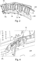
- FIG. 11 shows a sectional view of the embodiment according to FIG Fig. 2 and 3 . It can be seen in particular that the cooling air 31 which flows out through the outflow openings 29 is passed through a cooling air pocket 35. The cooling air 31 flows into this from a cooling air chamber 30.
- the Fig. 4 also shows an intermediate element / sealing strip 37, which serves as a seal for the platform gap and, according to the invention, together with the cooling air pocket 35, forms a cooling air duct 39 which determines the cooling air mass flow or guides the cooling air.
- cooling air pocket 35 the wall thickness of the blade platform only has to be reduced locally.
- the shape of the cooling air pockets 35 can be designed differently, for example with a rectangular cross section, an oval cross section, angular or rounded. Furthermore, it is possible to vary the angle between the cooling air pocket 35 and the platform upper side 33 in order to generate optimal flow and mass flow conditions for the respective application.
- the invention provides for the cooling air pockets 35 to be convergent or divergent in order to improve the flow paths and to influence temperature and pressure, or to use rounded shapes, in contrast to the conventionally used film cooling bores.
- a divergent shape, which is rounded, proves to be particularly advantageous in order to reduce the speed and the dynamic pressure of the cooling air flow and thereby to increase the static pressure and to reduce the temperature. Furthermore, there is a more even distribution of the cooling air over the axial length of the platform, see also Fig. 3 .
- the number and the position of the cooling air pockets can be varied over the entire axial length of the blade platform.
- the Fig. 3 further shows that in the adjacent blade platform (right blade platform according to FIG Fig. 3 ) an outflow pocket 34 is formed, into whose inflow opening 38 the cooling air flowing out of the outflow opening 29 of the cooling air pocket 35 enters. This is directed at a flat angle to the surface or platform top 33, so that both favorable flow conditions and optimized temperature and pressure conditions result.
- the outflow pocket 34 ensures a direct and unimpeded flow of cooling air between the entry of the cavity under the inner blade platform (cooling air chamber 30 or cooling air plenum) and the exit from the convex platform top 33.
- the cooling air film can spread better on the platform upper side 33 with the aid of the outflow pocket 34 and is less severely detached.
- the shape of the outflow pocket 34 can be adapted according to requirements, but it is preferably as flat as possible designed to rise and strongly rounded in order to avoid detachment of the cooling air film and detachment edges and thus turbulence and losses.
- Another advantage of the outflow pocket 34 is that tolerance-related radial steps between adjacent blade platforms 25 can be reduced to avoid the main flow separating over an edge and thus causing additional flow losses and an associated reduction in turbine efficiency.
- the design of the outflow pocket 34 can be varied in terms of shape, geometry, angle, number, length and position in order to meet the cooling requirements. For example, it is possible according to the invention to design the outflow pocket 34 over the entire axial length of the blade platform 25. Thus, on the one hand, the losses due to the tolerance-related radial steps between adjacent blade platforms 25 are reduced and, on the other hand, the rear part of the blade platform 25 is also effectively cooled.
- a second outflow pocket can also be provided, which ensures that a sufficient cooling air mass flow can flow between adjacent blade platforms even when the intermediate platform gap 32 is closed.
- the configuration according to the invention can be produced using existing production methods; it can be implemented cost-effectively, for example, when casting the blade platforms.
- the solution according to the invention is furthermore less prone to contamination and blockages from foreign bodies.
- the ratio between the width and height of the The cooling air pocket can be changed without adversely affecting the radial position in order to reduce the susceptibility to blockages.
- the invention ensures a reduction in the flow losses in the case of tolerance-related stages between adjacent blade platforms.
- the invention can be used both in aircraft gas turbines and in stationary industrial gas turbines or, quite generally, in gas turbines or turbo machines.
Description
Die Erfindung bezieht sich auf einen Stator einer Hochdruckturbine und/oder einer Mitteldruckturbine und/oder einer Niederdruckturbine einer Fluggasturbine oder einer stationären Industriegasturbine gemäß den Merkmalen des Oberbegriffs des Anspruches 1.The invention relates to a stator of a high pressure turbine and / or a medium pressure turbine and / or a low pressure turbine of an aircraft gas turbine or a stationary industrial gas turbine according to the features of the preamble of
Im Einzelnen bezieht sich die Erfindung auf die Ausgestaltung von inneren und/oder äußeren Schaufelplattformen, an denen jeweils eine oder mehrere Statorschaufeln ausgebildet sind. Zwischen den Schaufelplattformen ist eine Kühlluftkammer vorgesehen, um Kühlluft zwischen benachbarten Schaufelplattformen durchzuführen.In detail, the invention relates to the design of inner and / or outer blade platforms, on each of which one or more stator blades are formed. A cooling air chamber is provided between the blade platforms in order to pass cooling air through between adjacent blade platforms.
Zur Kühlung von Schaufelplattformen von Statorschaufeln zeigt der Stand der Technik eine mögliche Lösungsvariante mittels Filmkühlungsbohrungen. Nachteilig daran sind die aufwendige Fertigung sowie die Gefahr des Auftretens von Verstopfungen der Löcher durch Fremdpartikel und eine unter bestimmten Aspekten auftretende ungleichmäßige Verteilung des Kühlluftfilms und/oder mangelhafter Ausbildung eines Kühlluftfilms aufgrund fertigungstechnischer Limitationen. Unter Umständen ist auch die Zugänglichkeit für Werkzeuge zur Herstellung der erwähnten Filmkühlungsbohrungen limitiert.For the cooling of blade platforms of stator blades, the prior art shows a possible solution variant by means of film cooling bores. Disadvantages of this are the complex production and the risk of blockages of the holes by foreign particles and an uneven distribution of the cooling air film and / or poor formation of a cooling air film due to manufacturing limitations. Under certain circumstances, the accessibility for tools for producing the film cooling holes mentioned is also limited.
Aus der
Die
Eine weitere Konstruktion zeigt die
Der Erfindung liegt die Aufgabe zugrunde, einen Stator der eingangs genannten Art zu schaffen, welcher bei einfachem Aufbau und einfacher, kostengünstiger Herstellbarkeit eine effizientere Reduzierung der Oberflächenmetalltemperatur der inneren oder äußeren Schaufelplattform ermöglicht.The invention is based on the object of creating a stator of the type mentioned at the beginning which, with a simple structure and simple, cost-effective manufacturability, enables a more efficient reduction of the surface metal temperature of the inner or outer blade platform.
Erfindungsgemäß wird die Aufgabe durch die Merkmalskombination des Anspruchs 1 gelöst, die Unteransprüche zeigen weitere vorteilhafte Ausgestaltungen der Erfindung.According to the invention, the object is achieved by the combination of features in
Die Erfindung beschreibt somit einen Stator einer Turbine einer Gasturbine, mit einem Strömungskanal, in welchem Leitschaufeln angeordnet sind, welche jeweils eine äußere und eine innere Schaufelplattform aufweisen, sowie mit jeweils einer durch benachbarte Schaufelplattformen gebildeten Kühlluftkammer oder einem Kühlluftplenum zur Durchführung von Kühlluft, wobei die sich ergebende Kühlluftkammer und/oder ein Plattformzwischenspalt so ausgebildet sind, dass, ausgehend von einer der benachbarten Schaufelplattform zugewandten Seite der Schaufelplattform, zumindest eine zu einer Plattformoberseite offene, mit der Kühlluftkammer in Verbindung stehende Ausströmtasche ausgebildet ist und wobei in der Wandung der Kühlluftkammer zumindest eine radial nach innen zur Kühlluftkammer geöffnete Kühllufttasche ausgebildet ist, welche sich zu dem Plattformzwischenspalt öffnet.The invention thus describes a stator of a turbine of a gas turbine, with a flow channel in which guide vanes are arranged, each having an outer and an inner vane platform, as well as with a cooling air chamber formed by adjacent vane platforms or a cooling air plenum for the passage of cooling air, the The resulting cooling air chamber and / or an intermediate platform gap are designed in such a way that, starting from a side of the blade platform facing the adjacent blade platform, at least one outflow pocket that is open to the top of the platform and communicating with the cooling air chamber is formed and at least one in the wall of the cooling air chamber is formed radially inwardly to the cooling air chamber open cooling air pocket which opens to the platform gap.
Erfindungsgemäß ist somit vorgesehen, die Kühlluft durch die Ausströmtasche zu leiten und auf diese Weise einen Austritt der Kühlluft und insbesondere eine Filmbildung der Kühlluft auf der Plattformoberseite vorzusehen.According to the invention, it is thus provided to guide the cooling air through the outflow pocket and in this way to provide an exit of the cooling air and in particular a film formation of the cooling air on the upper side of the platform.
Erfindungsgemäß ist somit vorgesehen, an der Oberfläche der jeweiligen Schaufelplattform eine Ausströmtasche vorzusehen. Diese ist somit radial außen an der Oberfläche oder Oberseite der Schaufelplattform angeordnet und erstreckt sich sowohl in axialer Richtung als auch in Umfangsrichtung. Die Tiefe der Ausströmtasche ist in radialer Richtung vorgesehen. Es ergibt sich somit eine für die Ausströmung der Kühlluft vorgesehene Ausströmtasche, welche sich in allen drei Dimensionen erstreckt und zur Strömungsoptimierung ausgeformt ist. Im Gegensatz zum Stand der Technik, bei welchem nur einfache Schlitze oder Nuten zwischen den Schaufelplattformen vorgesehen sind, ermöglicht die erfindungsgemäße Ausströmtasche somit auch bei einem Schließen des Plattformzwischenspalts durch thermische Ausdehnungen eine direkte und gezielte Filmkühlung der Plattformoberseite. Während beim Stand der Technik die Schlitze oder Nuten zwischen den Schaufelplattformen eine mehrfache Umlenkung der Strömung der Kühlluft erforderlich machen, wird erfindungsgemäß die Möglichkeit geschaffen, in jedem Betriebspunkt eine störungsfreie Ausströmung der Kühlluft ohne Umlenkung zu realisieren.According to the invention, provision is therefore made for an outflow pocket to be provided on the surface of the respective blade platform. This is thus arranged radially on the outside on the surface or top of the blade platform and extends both in the axial direction and in the circumferential direction. The depth of the outflow pocket is provided in the radial direction. There is thus one for the outflow of the An outflow pocket provided for cooling air, which extends in all three dimensions and is shaped to optimize the flow. In contrast to the prior art, in which only simple slots or grooves are provided between the blade platforms, the outflow pocket according to the invention thus enables direct and targeted film cooling of the platform top even when the platform gap is closed by thermal expansion. While in the prior art the slots or grooves between the blade platforms require multiple diversions of the flow of the cooling air, the invention creates the possibility of realizing a trouble-free outflow of the cooling air without diversion at every operating point.
Weiterhin ist bei der Erfindung in der Wandung der Kühlluftkammer eine radial nach innen zur Kühlluftkammer geöffnete Kühllufttasche ausgebildet, welche sich zum Plattformzwischenspalt öffnet. Durch diese zusätzliche Kühllufttasche erfolgt die Einleitung der Kühlluft in die Ausströmtasche(n) in optimaler Weise.Furthermore, in the case of the invention, in the wall of the cooling air chamber, a cooling air pocket, which is open radially inward towards the cooling air chamber and which opens towards the platform gap, is formed. Through this additional cooling air pocket, the cooling air is introduced into the outflow pocket (s) in an optimal manner.
Durch die erfindungsgemäße Ausgestaltung ist es möglich, die Oberflächenmetalltemperatur an der Plattform weiter gegenüber der Kühlung gemäß dem Stand der Technik zu reduzieren oder die Kühlluftverteilung zu Verbessern.The configuration according to the invention makes it possible to further reduce the surface metal temperature on the platform compared to the cooling according to the prior art or to improve the cooling air distribution.
Erfindungsgemäß wird der Gesamtströmungskanal der Kühlluft mit Hilfe der benachbarten Schaufelplattformen, deren Kühllufttaschen und Ausströmtaschen, sowie der Zwischenelemente / Dichtstreifen gebildet. Erfindungsgemäß kann somit auf aufwendig herstellbare interne und/oder geschlossene Kühlluftkanäle (Filmkühlungsbohrungen) verzichtet werden.According to the invention, the total flow channel of the cooling air is formed with the aid of the adjacent blade platforms, their cooling air pockets and outflow pockets, and the intermediate elements / sealing strips. According to the invention, internal and / or closed cooling air channels (film cooling bores) that are complex to manufacture can thus be dispensed with.
Die Kühllufttasche kann erfindungsgemäß konvergent oder divergent ausgebildet sein. Besonders günstig ist es weiterhin, wenn die Ausströmtasche mit einem möglichst flachen Winkel, idealerweise in einem Winkel zwischen 0° und 35°, zur Plattformoberseite geöffnet oder angeordnet ist. Alternativ kann die Ausströmtasche auch als Freiformfläche strömungsgerecht ausgebildet werden, wobei diese Ausgestaltung bevorzugt in beiden Ebenen vorgesehen ist. Diese Maßnahmen verbessern die Anlage eines Kühlluftfilms auf die Oberfläche der Schaufelplattform. Zur Verbesserung der Strömung trägt auch bei, wenn die Ausströmtasche und/oder die Kühllufttasche jeweils mit freiausgeformten Flächen und/oder Wandungen versehen sind. Insbesondere eine divergente Form der Kühllufttasche (ähnlich einem Diffusor) ermöglicht zum einen eine Geschwindigkeitsabsenkung sowie zum anderen eine Druckerhöhung des Kühlluftmassenstroms, welche zu einer verbesserten Ausprägung des Films führen. Im Radialschnitt sowie in der Draufsicht (vgl.
Weiterhin kann vorgesehen sein, dass die beschriebene Ausführung der Ausströmtasche und/oder der Kühllufttasche in ähnlicher Form an der äußeren Heißgasplattformoberfläche (Schaufelspitze) ausgebildet ist. Die Ausströmtasche kann auch eine weitere Durchströmausnehmung in integraler Ausführung in vorwiegend radialer Orientierung aufweisen.Furthermore, it can be provided that the described embodiment of the outflow pocket and / or the cooling air pocket is designed in a similar shape on the outer hot gas platform surface (blade tip). The outflow pocket can also have a further throughflow recess in an integral design in a predominantly radial orientation.
Nachfolgend wird die Erfindung anhand eines Ausführungsbeispiels in Verbindung mit der Zeichnung beschrieben. Dabei zeigt:
- Fig. 1
- eine schematische Darstellung eines Gasturbinentriebwerks gemäß der vorliegenden Erfindung,
- Fig. 2
- eine perspektivische Teilansicht von erfindungsgemäßen Statorschaufeln mit zugehörigen Schaufelplattformen,
- Fig. 3
- eine vergrößerte perspektivische Teilansicht einer Ausströmtasche, und
- Fig. 4
- eine Schnittansicht, analog
Fig. 3 .
- Fig. 1
- a schematic representation of a gas turbine engine according to the present invention,
- Fig. 2
- a perspective partial view of stator blades according to the invention with associated blade platforms,
- Fig. 3
- an enlarged perspective partial view of an outflow pocket, and
- Fig. 4
- a sectional view, analog
Fig. 3 .
Das Gasturbinentriebwerk 10 gemäß
Der Mitteldruckkompressor 13 und der Hochdruckkompressor 14 umfassen jeweils mehrere Stufen, von denen jede eine in Umfangsrichtung verlaufende Anordnung fester stationärer Leitschaufeln 20 aufweist, die allgemein als Statorschaufeln bezeichnet werden und die radial nach innen vom Kerntriebwerksgehäuse 21 in einen ringförmigen Strömungskanal durch die Kompressoren 13, 14 vorstehen. Die Kompressoren weisen weiter eine Anordnung von Kompressorlaufschaufeln 22 auf, die radial nach außen von einer drehbaren Trommel oder Scheibe 26 vorstehen, die mit Naben 27 der Hochdruckturbine 16 bzw. der Mitteldruckturbine 17 gekoppelt sind.The
Die Turbinenabschnitte 16, 17, 18 weisen ähnliche Stufen auf, umfassend eine Anordnung von festen Leitschaufeln 23, die in der Regel radial nach innen vom Gehäuse 21 in den ringförmigen Strömungskanal durch die Turbinen 16, 17, 18 vorstehen, und eine nachfolgende Anordnung von Turbinenrotorschaufeln 24, die nach außen von einer drehbaren Nabe 27 vorstehen. Die Kompressortrommel oder Kompressorscheibe 26 und die darauf angeordneten Schaufeln 22 sowie die Turbinenrotornabe 27 und die darauf angeordneten Turbinenrotorschaufeln 24 drehen sich im Betrieb um die Triebwerksachse 1. Ein Auslasskonus ist mit 28 bezeichnet.The
Die
In der nachfolgenden Beschreibung wird zur Vereinfachung der Darstellung auf die radial innere (bezogen auf die Triebwerksachse 1) Schaufelplattform Bezug genommen, die Erfindung kann in analoger Weise auch an der äußeren Schaufelplattform vorgesehen sein.In the following description, in order to simplify the representation, reference is made to the radially inner blade platform (with reference to the engine axis 1); the invention can also be provided in an analogous manner on the outer blade platform.
Die
Wie sich insbesondere aus der Darstellung der
Die
Die
Zur Ausbildung der Kühllufttasche 35 muss die Wandstärke der Schaufelplattform nur lokal verringert werden. Die Form der Kühllufttaschen 35 (Kühlungskanäle) kann unterschiedlich ausgebildet werden, beispielsweise mit einem rechteckigen Querschnitt, einem ovalen Querschnitt, eckig oder abgerundet. Weiterhin ist es möglich, den Winkel zwischen der Kühllufttasche 35 und der Plattformoberseite 33 zu variieren, um optimale Strömungs- und Massenstromverhältnisse für den jeweiligen Anwendungsfall zu erzeugen.To form the cooling
So ist es erfindungsgemäß vorgesehen, die Kühllufttaschen 35 zur Verbesserung der Strömungspfade und zur Beeinflussung von Temperatur und Druck konvergent oder divergent auszugestalten oder abgerundete Formen zu verwenden, im Gegensatz zu den herkömmlich verwendeten Filmkühlungsbohrungen. Eine divergente Form, welche abgerundet ausgebildet ist, erweist sich als besonders vorteilhaft, um die Geschwindigkeit und den dynamischen Druck der Kühlluftströmung zu verringern und dadurch den statischen Druck zu erhöhen und die Temperatur zu verringern. Weiterhin ergibt sich eine gleichmäßigere Verteilung der Kühlluft über die axiale Länge der Plattform, siehe hierzu auch
Erfindungsgemäß kann abhängig von den Kühlungsanforderungen die Anzahl und die Lage der Kühllufttaschen über die gesamte axiale Länge der Schaufelplattform variiert werden.According to the invention, depending on the cooling requirements, the number and the position of the cooling air pockets can be varied over the entire axial length of the blade platform.
Die
Ein weiterer Vorteil der Ausströmtasche 34 besteht darin, dass toleranzbedingte radiale Stufen zwischen benachbarten Schaufelplattformen 25 reduziert werden können, um zu vermeiden, dass die Hauptströmung über eine Kante ablöst und so zusätzliche Strömungsverluste und eine damit verbundene Verringerung des Turbinenwirkungsgrades verursacht.Another advantage of the
Die Ausgestaltung der Ausströmtasche 34 kann in Form, Geometrie, Winkel, Anzahl, Länge und Lage variiert werden, um den Kühlungsanforderungen gerecht zu werden. Beispielsweise ist es erfindungsgemäß möglich, die Ausströmtasche 34 über die gesamte axiale Länge der Schaufelplattform 25 auszuführen. Somit werden zum einen die Verluste aufgrund der toleranzbedingten radiale Stufen zwischen benachbarten Schaufelplattformen 25 reduziert und zum anderen auch der hintere Teil der Schaufelplattform 25 effektiv gekühlt.The design of the
Erfindungsgemäß kann außerdem eine zweite Ausströmtasche vorgesehen werden, welche dafür sorgt, dass auch bei geschlossenem Plattformzwischenspalt 32 zwischen benachbarten Schaufelplattformen ein ausreichender Kühlluftmassenstrom strömen kann.According to the invention, a second outflow pocket can also be provided, which ensures that a sufficient cooling air mass flow can flow between adjacent blade platforms even when the
Erfindungsgemäß ergeben sich somit die folgenden Vorteile:
Erfindungsgemäß kann eine großflächigere Kühlung als mittels herkömmlicher Filmkühlungsbohrungen bei geringerem Fertigungsaufwand realisiert werden.According to the invention, the following advantages thus result:
According to the invention, cooling over a larger area than by means of conventional film cooling bores can be implemented with less manufacturing effort.
Die erfindungsgemäße Ausgestaltung ist mit existierenden Herstellungsmethoden zu fertigen, sie kann beispielsweise beim Guss der Schaufelplattformen kostengünstig realisiert werden.The configuration according to the invention can be produced using existing production methods; it can be implemented cost-effectively, for example, when casting the blade platforms.
Die erfindungsgemäße Lösung ist weiterhin weniger anfällig für Verschmutzungen und Blockaden durch Fremdkörper. Das Verhältnis zwischen Breite und Höhe der Kühllufttasche kann ohne negative Beeinflussung der radialen Position geändert werden, um eine Reduzierung der Anfälligkeit für Blockaden zu erreichen.The solution according to the invention is furthermore less prone to contamination and blockages from foreign bodies. The ratio between the width and height of the The cooling air pocket can be changed without adversely affecting the radial position in order to reduce the susceptibility to blockages.
Es ergibt sich eine höhere Flexibilität bezüglich der Geometrie der Kühlungskanäle, im Vergleich zu konventionellen Filmbohrungen, insbesondere der Kühllufttasche 35 und der Ausströmtasche 34. Dies ist insbesondere bei einer integralen Ausführung vorteilhaft. Es ergibt sich insgesamt eine gezielte Optimierung der Plattformkühlung.This results in greater flexibility with regard to the geometry of the cooling channels compared to conventional film bores, in particular the cooling
Durch die Erfindung ist eine Verringerung der Strömungsverluste bei toleranzbedingten Stufen zwischen benachbarten Schaufelplattformen sichergestellt.The invention ensures a reduction in the flow losses in the case of tolerance-related stages between adjacent blade platforms.
Die Erfindung ist sowohl bei Fluggasturbinen als auch bei stationären Industriegasturbinen oder ganz allgemein bei Gasturbinen oder Turbomaschinen anwendbar.The invention can be used both in aircraft gas turbines and in stationary industrial gas turbines or, quite generally, in gas turbines or turbo machines.
- 11
- TriebwerksachseEngine axis
- 1010
- Gasturbinentriebwerk / KerntriebwerkGas turbine engine / core engine
- 1111
- LufteinlassAir inlet
- 1212
- Fanfan
- 1313
- Mitteldruckkompressor (Verdichter)Medium pressure compressor (compressor)
- 1414th
- HochdruckkompressorHigh pressure compressor
- 1515th
- BrennkammerCombustion chamber
- 1616
- HochdruckturbineHigh pressure turbine
- 1717th
- MitteldruckturbineMedium pressure turbine
- 1818th
- NiederdruckturbineLow pressure turbine
- 1919th
- AbgasdüseExhaust nozzle
- 2020th
- LeitschaufelnGuide vanes
- 2121st
- KerntriebwerksgehäuseCore engine casing
- 2222nd
- KompressorlaufschaufelnCompressor blades
- 2323
- LeitschaufelnGuide vanes
- 2424
- TurbinenrotorschaufelnTurbine rotor blades
- 2525th
- SchaufelplattformShovel platform
- 2626th
- Kompressortrommel oder -scheibeCompressor drum or disk
- 2727
- TurbinenrotornabeTurbine rotor hub
- 2828
- AuslasskonusOutlet cone
- 2929
- AusströmöffnungOutlet opening
- 3030th
- KühlluftkammerCooling air chamber
- 3131
- KühlluftCooling air
- 3232
- PlattformzwischenspaltPlatform gap
- 3333
- PlattformoberseitePlatform top
- 3434
- AusströmtascheOutflow pocket
- 3535
- KühllufttascheCooling air pocket
- 3636
- HeißgasHot gas
- 3737
- Zwischenelement / DichtstreifenIntermediate element / sealing strip
- 3838
- EinströmöffnungInflow opening
- 3939
- KühlluftkanalCooling air duct
Claims (11)
- Stator of a turbine of a gas turbine, having a flow channel in which there are arranged guide vanes (23), which each have an outer and an inner vane platform (25), and having in each case a cooling-air chamber (30) which is formed by adjacent vane platforms (25) and serves for the passage of cooling air, characterized in that the resulting cooling-air chamber (30) and/or a platform intermediate gap (32) are/is formed in such a way that, proceeding from a side of the vane platform (25), which side faces the adjacent vane platform (25), there is formed at least one outflow pocket (34) which is open towards a platform top side (33) and which is connected to the cooling-air chamber (30), and in that, in the wall of the cooling-air chamber (30), there is formed at least one cooling-air pocket (35) which is open radially inwardly towards the cooling-air chamber (30) and which is delimited by an intermediate element or a sealing strip (37) and which opens towards the platform intermediate gap (32).
- Stator according to Claim 1, characterized in that only one cooling-air pocket (35) is arranged at a vane platform (25).
- Stator according to Claim 1 and/or 2, characterized in that the cooling-air pocket (35) is of convergent or divergent form.
- Stator according to one or more of Claims 1 to 3, characterized in that the outflow pocket (34) is formed at a shallow angle or tangentially with respect to the platform top side (33).
- Stator according to one or more of Claims 1 to 4, characterized in that the outflow pocket (34) is formed with surfaces which merge freely into one another.
- Stator according to one or more of Claims 1 to 5, characterized in that the walls of the cooling-air pocket (35) are formed so as to merge freely into one another.
- Stator according to one or more of Claims 1 to 6, characterized in that the outflow pocket (34) has a further throughflow cutout formed in an integral manner with a predominantly radial orientation.
- Stator according to one or more of Claims 1 to 7, characterized in that, over the axial length of the vane platform (25), there are arranged multiple outflow pockets (34) or there is arranged an outflow pocket taking up the entire length.
- Stator according to one or more of Claims 1 to 8, characterized in that multiple cooling-air pockets (35) are arranged over the axial length of the vane platform (25).
- Stator according to Claim 9, characterized in that the multiple cooling-air pockets (35) are formed so as to completely or partially merge into one another.
- Stator according to one or more of Claims 1 to 10, characterized in that the outflow pocket (34) and/or the cooling-air pocket (35) are/is formed at a radially outer hot-gas platform surface.
Applications Claiming Priority (1)
| Application Number | Priority Date | Filing Date | Title |
|---|---|---|---|
| DE102015203872.6A DE102015203872A1 (en) | 2015-03-04 | 2015-03-04 | Stator of a turbine of a gas turbine with improved cooling air flow |
Publications (2)
| Publication Number | Publication Date |
|---|---|
| EP3159487A1 EP3159487A1 (en) | 2017-04-26 |
| EP3159487B1 true EP3159487B1 (en) | 2021-01-20 |
Family
ID=55451137
Family Applications (1)
| Application Number | Title | Priority Date | Filing Date |
|---|---|---|---|
| EP16158540.1A Active EP3159487B1 (en) | 2015-03-04 | 2016-03-03 | Stator of a turbine of a gas turbine with improved cooling air conduction |
Country Status (3)
| Country | Link |
|---|---|
| US (1) | US10041352B2 (en) |
| EP (1) | EP3159487B1 (en) |
| DE (1) | DE102015203872A1 (en) |
Families Citing this family (3)
| Publication number | Priority date | Publication date | Assignee | Title |
|---|---|---|---|---|
| FR3095003B1 (en) * | 2019-04-15 | 2022-07-08 | Safran Aircraft Engines | Turbine blade having a platform cooling slot |
| US11506129B2 (en) | 2020-04-24 | 2022-11-22 | Raytheon Technologies Corporation | Feather seal mateface cooling pockets |
| CN114934821B (en) * | 2022-06-29 | 2023-10-03 | 华能鹤岗发电有限公司 | High-safety low-heat-consumption steam turbine |
Family Cites Families (12)
| Publication number | Priority date | Publication date | Assignee | Title |
|---|---|---|---|---|
| US3752598A (en) * | 1971-11-17 | 1973-08-14 | United Aircraft Corp | Segmented duct seal |
| JPH03213602A (en) * | 1990-01-08 | 1991-09-19 | General Electric Co <Ge> | Self cooling type joint connecting structure to connect contact segment of gas turbine engine |
| GB2280935A (en) | 1993-06-12 | 1995-02-15 | Rolls Royce Plc | Cooled sealing strip for nozzle guide vane segments |
| US5531457A (en) * | 1994-12-07 | 1996-07-02 | Pratt & Whitney Canada, Inc. | Gas turbine engine feather seal arrangement |
| EP1260678B1 (en) | 1997-09-15 | 2004-07-07 | ALSTOM Technology Ltd | Segment arrangement for platforms |
| JP3999395B2 (en) | 1999-03-03 | 2007-10-31 | 三菱重工業株式会社 | Gas turbine split ring |
| SE0502644L (en) * | 2005-12-02 | 2007-06-03 | Siemens Ag | Cooling platforms for turbine blades in turbines |
| WO2008122507A1 (en) | 2007-04-05 | 2008-10-16 | Alstom Technology Ltd | Shiplap arrangement |
| US7600721B2 (en) | 2007-07-23 | 2009-10-13 | Panduit Corp. | Network cable bundling tool |
| GB0806893D0 (en) * | 2008-04-16 | 2008-05-21 | Rolls Royce Plc | A damper |
| DE102009004792B4 (en) * | 2009-01-13 | 2019-10-31 | Rolls-Royce Deutschland Ltd & Co Kg | Damping element (friction damper) with sealing function for turbine blades |
| US8684673B2 (en) * | 2010-06-02 | 2014-04-01 | Siemens Energy, Inc. | Static seal for turbine engine |
-
2015
- 2015-03-04 DE DE102015203872.6A patent/DE102015203872A1/en not_active Withdrawn
-
2016
- 2016-03-01 US US15/057,288 patent/US10041352B2/en active Active
- 2016-03-03 EP EP16158540.1A patent/EP3159487B1/en active Active
Non-Patent Citations (1)
| Title |
|---|
| None * |
Also Published As
| Publication number | Publication date |
|---|---|
| EP3159487A1 (en) | 2017-04-26 |
| DE102015203872A1 (en) | 2016-09-22 |
| US10041352B2 (en) | 2018-08-07 |
| US20160258293A1 (en) | 2016-09-08 |
Similar Documents
| Publication | Publication Date | Title |
|---|---|---|
| EP3093447B1 (en) | Rotor of a turbine of a gas turbine with improved cooling air conduction | |
| EP2725194B1 (en) | Turbine rotor blade of a gas turbine | |
| EP2886961B1 (en) | Washer of a combustion chamber shingle of a gas turbine | |
| EP3101231B1 (en) | Device for cooling a wall of a component of a gas turbine | |
| EP3182011B1 (en) | Wall of a component to be cooled using air cooling, in particular of a gas turbine combustion chamber wall | |
| EP2770260B1 (en) | Gas turbine combustion chamber with impingement effusion cooled shingle | |
| EP2824282A1 (en) | Gas turbine with high pressure turbine cooling system | |
| EP2179143B1 (en) | Gap cooling between combustion chamber wall and turbine wall of a gas turbine installation | |
| EP3121372A1 (en) | Cooled turbine wheel for an aircraft engine | |
| DE60017396T2 (en) | DEVICE FOR REDUCING COOLING FOR A TURBINE ENTRY CHANNEL | |
| EP2881541A1 (en) | Tip cooling of a turbine rotor blade of a gas turbine | |
| EP3121373B1 (en) | Cooled turbine wheel, in particular for an aircraft engine | |
| DE102008055522A1 (en) | Divergent turbine nozzle | |
| DE102015219556A1 (en) | Diffuser for radial compressor, centrifugal compressor and turbo machine with centrifugal compressor | |
| EP2818724B1 (en) | Fluid flow engine and method | |
| DE102015120127A1 (en) | AXIAL COMPRESSOR DEVICE FOR CONTROLLING THE LEAKAGE IN THIS | |
| CH708795A2 (en) | Segment for an annular rotary machine Leitradbauteil. | |
| DE102009040758A1 (en) | Deflection device for a leakage current in a gas turbine and gas turbine | |
| DE102007061564A1 (en) | Turbine blade for use in gas turbine engine, has cooling slot with inlet end that is in flow connection with cooling duct for receiving fluid, and outlet end adjacent to rear edge of blade | |
| CH702000B1 (en) | Device with swirl chambers to the gap flow control in a turbine stage. | |
| EP2808559A1 (en) | Structure assembly for a turbomachine | |
| EP2746533A1 (en) | Blade grid and turbomachine | |
| EP2808556B1 (en) | Structure assembly for a turbo machine | |
| EP3159487B1 (en) | Stator of a turbine of a gas turbine with improved cooling air conduction | |
| EP0992656B1 (en) | Turbomachine to compress or expand a compressible medium |
Legal Events
| Date | Code | Title | Description |
|---|---|---|---|
| PUAI | Public reference made under article 153(3) epc to a published international application that has entered the european phase |
Free format text: ORIGINAL CODE: 0009012 |
|
| STAA | Information on the status of an ep patent application or granted ep patent |
Free format text: STATUS: THE APPLICATION HAS BEEN PUBLISHED |
|
| AK | Designated contracting states |
Kind code of ref document: A1 Designated state(s): AL AT BE BG CH CY CZ DE DK EE ES FI FR GB GR HR HU IE IS IT LI LT LU LV MC MK MT NL NO PL PT RO RS SE SI SK SM TR |
|
| AX | Request for extension of the european patent |
Extension state: BA ME |
|
| STAA | Information on the status of an ep patent application or granted ep patent |
Free format text: STATUS: REQUEST FOR EXAMINATION WAS MADE |
|
| 17P | Request for examination filed |
Effective date: 20170612 |
|
| RBV | Designated contracting states (corrected) |
Designated state(s): AL AT BE BG CH CY CZ DE DK EE ES FI FR GB GR HR HU IE IS IT LI LT LU LV MC MK MT NL NO PL PT RO RS SE SI SK SM TR |
|
| RIC1 | Information provided on ipc code assigned before grant |
Ipc: F01D 9/02 20060101ALI20200623BHEP Ipc: F01D 11/00 20060101AFI20200623BHEP |
|
| GRAP | Despatch of communication of intention to grant a patent |
Free format text: ORIGINAL CODE: EPIDOSNIGR1 |
|
| STAA | Information on the status of an ep patent application or granted ep patent |
Free format text: STATUS: GRANT OF PATENT IS INTENDED |
|
| INTG | Intention to grant announced |
Effective date: 20200731 |
|
| GRAS | Grant fee paid |
Free format text: ORIGINAL CODE: EPIDOSNIGR3 |
|
| GRAA | (expected) grant |
Free format text: ORIGINAL CODE: 0009210 |
|
| STAA | Information on the status of an ep patent application or granted ep patent |
Free format text: STATUS: THE PATENT HAS BEEN GRANTED |
|
| RIN1 | Information on inventor provided before grant (corrected) |
Inventor name: LEYMANN, TOBIAS Inventor name: WEINERT, MARKUS |
|
| AK | Designated contracting states |
Kind code of ref document: B1 Designated state(s): AL AT BE BG CH CY CZ DE DK EE ES FI FR GB GR HR HU IE IS IT LI LT LU LV MC MK MT NL NO PL PT RO RS SE SI SK SM TR |
|
| REG | Reference to a national code |
Ref country code: GB Ref legal event code: FG4D Free format text: NOT ENGLISH |
|
| REG | Reference to a national code |
Ref country code: CH Ref legal event code: EP |
|
| REG | Reference to a national code |
Ref country code: DE Ref legal event code: R096 Ref document number: 502016012222 Country of ref document: DE |
|
| REG | Reference to a national code |
Ref country code: AT Ref legal event code: REF Ref document number: 1356572 Country of ref document: AT Kind code of ref document: T Effective date: 20210215 |
|
| REG | Reference to a national code |
Ref country code: IE Ref legal event code: FG4D Free format text: LANGUAGE OF EP DOCUMENT: GERMAN |
|
| REG | Reference to a national code |
Ref country code: NL Ref legal event code: MP Effective date: 20210120 |
|
| REG | Reference to a national code |
Ref country code: LT Ref legal event code: MG9D |
|
| PG25 | Lapsed in a contracting state [announced via postgrant information from national office to epo] |
Ref country code: PT Free format text: LAPSE BECAUSE OF FAILURE TO SUBMIT A TRANSLATION OF THE DESCRIPTION OR TO PAY THE FEE WITHIN THE PRESCRIBED TIME-LIMIT Effective date: 20210520 Ref country code: NO Free format text: LAPSE BECAUSE OF FAILURE TO SUBMIT A TRANSLATION OF THE DESCRIPTION OR TO PAY THE FEE WITHIN THE PRESCRIBED TIME-LIMIT Effective date: 20210420 Ref country code: BG Free format text: LAPSE BECAUSE OF FAILURE TO SUBMIT A TRANSLATION OF THE DESCRIPTION OR TO PAY THE FEE WITHIN THE PRESCRIBED TIME-LIMIT Effective date: 20210420 Ref country code: NL Free format text: LAPSE BECAUSE OF FAILURE TO SUBMIT A TRANSLATION OF THE DESCRIPTION OR TO PAY THE FEE WITHIN THE PRESCRIBED TIME-LIMIT Effective date: 20210120 Ref country code: HR Free format text: LAPSE BECAUSE OF FAILURE TO SUBMIT A TRANSLATION OF THE DESCRIPTION OR TO PAY THE FEE WITHIN THE PRESCRIBED TIME-LIMIT Effective date: 20210120 Ref country code: GR Free format text: LAPSE BECAUSE OF FAILURE TO SUBMIT A TRANSLATION OF THE DESCRIPTION OR TO PAY THE FEE WITHIN THE PRESCRIBED TIME-LIMIT Effective date: 20210421 Ref country code: FI Free format text: LAPSE BECAUSE OF FAILURE TO SUBMIT A TRANSLATION OF THE DESCRIPTION OR TO PAY THE FEE WITHIN THE PRESCRIBED TIME-LIMIT Effective date: 20210120 Ref country code: LT Free format text: LAPSE BECAUSE OF FAILURE TO SUBMIT A TRANSLATION OF THE DESCRIPTION OR TO PAY THE FEE WITHIN THE PRESCRIBED TIME-LIMIT Effective date: 20210120 |
|
| PG25 | Lapsed in a contracting state [announced via postgrant information from national office to epo] |
Ref country code: SE Free format text: LAPSE BECAUSE OF FAILURE TO SUBMIT A TRANSLATION OF THE DESCRIPTION OR TO PAY THE FEE WITHIN THE PRESCRIBED TIME-LIMIT Effective date: 20210120 Ref country code: PL Free format text: LAPSE BECAUSE OF FAILURE TO SUBMIT A TRANSLATION OF THE DESCRIPTION OR TO PAY THE FEE WITHIN THE PRESCRIBED TIME-LIMIT Effective date: 20210120 Ref country code: RS Free format text: LAPSE BECAUSE OF FAILURE TO SUBMIT A TRANSLATION OF THE DESCRIPTION OR TO PAY THE FEE WITHIN THE PRESCRIBED TIME-LIMIT Effective date: 20210120 Ref country code: LV Free format text: LAPSE BECAUSE OF FAILURE TO SUBMIT A TRANSLATION OF THE DESCRIPTION OR TO PAY THE FEE WITHIN THE PRESCRIBED TIME-LIMIT Effective date: 20210120 |
|
| PG25 | Lapsed in a contracting state [announced via postgrant information from national office to epo] |
Ref country code: IS Free format text: LAPSE BECAUSE OF FAILURE TO SUBMIT A TRANSLATION OF THE DESCRIPTION OR TO PAY THE FEE WITHIN THE PRESCRIBED TIME-LIMIT Effective date: 20210520 |
|
| REG | Reference to a national code |
Ref country code: DE Ref legal event code: R097 Ref document number: 502016012222 Country of ref document: DE |
|
| PG25 | Lapsed in a contracting state [announced via postgrant information from national office to epo] |
Ref country code: SM Free format text: LAPSE BECAUSE OF FAILURE TO SUBMIT A TRANSLATION OF THE DESCRIPTION OR TO PAY THE FEE WITHIN THE PRESCRIBED TIME-LIMIT Effective date: 20210120 Ref country code: EE Free format text: LAPSE BECAUSE OF FAILURE TO SUBMIT A TRANSLATION OF THE DESCRIPTION OR TO PAY THE FEE WITHIN THE PRESCRIBED TIME-LIMIT Effective date: 20210120 Ref country code: CZ Free format text: LAPSE BECAUSE OF FAILURE TO SUBMIT A TRANSLATION OF THE DESCRIPTION OR TO PAY THE FEE WITHIN THE PRESCRIBED TIME-LIMIT Effective date: 20210120 Ref country code: MC Free format text: LAPSE BECAUSE OF FAILURE TO SUBMIT A TRANSLATION OF THE DESCRIPTION OR TO PAY THE FEE WITHIN THE PRESCRIBED TIME-LIMIT Effective date: 20210120 |
|
| REG | Reference to a national code |
Ref country code: CH Ref legal event code: PL |
|
| PLBE | No opposition filed within time limit |
Free format text: ORIGINAL CODE: 0009261 |
|
| STAA | Information on the status of an ep patent application or granted ep patent |
Free format text: STATUS: NO OPPOSITION FILED WITHIN TIME LIMIT |
|
| PG25 | Lapsed in a contracting state [announced via postgrant information from national office to epo] |
Ref country code: SK Free format text: LAPSE BECAUSE OF FAILURE TO SUBMIT A TRANSLATION OF THE DESCRIPTION OR TO PAY THE FEE WITHIN THE PRESCRIBED TIME-LIMIT Effective date: 20210120 Ref country code: RO Free format text: LAPSE BECAUSE OF FAILURE TO SUBMIT A TRANSLATION OF THE DESCRIPTION OR TO PAY THE FEE WITHIN THE PRESCRIBED TIME-LIMIT Effective date: 20210120 Ref country code: ES Free format text: LAPSE BECAUSE OF FAILURE TO SUBMIT A TRANSLATION OF THE DESCRIPTION OR TO PAY THE FEE WITHIN THE PRESCRIBED TIME-LIMIT Effective date: 20210120 Ref country code: DK Free format text: LAPSE BECAUSE OF FAILURE TO SUBMIT A TRANSLATION OF THE DESCRIPTION OR TO PAY THE FEE WITHIN THE PRESCRIBED TIME-LIMIT Effective date: 20210120 |
|
| REG | Reference to a national code |
Ref country code: BE Ref legal event code: MM Effective date: 20210331 |
|
| 26N | No opposition filed |
Effective date: 20211021 |
|
| GBPC | Gb: european patent ceased through non-payment of renewal fee |
Effective date: 20210420 |
|
| PG25 | Lapsed in a contracting state [announced via postgrant information from national office to epo] |
Ref country code: GB Free format text: LAPSE BECAUSE OF NON-PAYMENT OF DUE FEES Effective date: 20210420 Ref country code: IE Free format text: LAPSE BECAUSE OF NON-PAYMENT OF DUE FEES Effective date: 20210303 Ref country code: LI Free format text: LAPSE BECAUSE OF NON-PAYMENT OF DUE FEES Effective date: 20210331 Ref country code: LU Free format text: LAPSE BECAUSE OF NON-PAYMENT OF DUE FEES Effective date: 20210303 Ref country code: AL Free format text: LAPSE BECAUSE OF FAILURE TO SUBMIT A TRANSLATION OF THE DESCRIPTION OR TO PAY THE FEE WITHIN THE PRESCRIBED TIME-LIMIT Effective date: 20210120 Ref country code: CH Free format text: LAPSE BECAUSE OF NON-PAYMENT OF DUE FEES Effective date: 20210331 |
|
| PG25 | Lapsed in a contracting state [announced via postgrant information from national office to epo] |
Ref country code: SI Free format text: LAPSE BECAUSE OF FAILURE TO SUBMIT A TRANSLATION OF THE DESCRIPTION OR TO PAY THE FEE WITHIN THE PRESCRIBED TIME-LIMIT Effective date: 20210120 |
|
| PG25 | Lapsed in a contracting state [announced via postgrant information from national office to epo] |
Ref country code: IT Free format text: LAPSE BECAUSE OF FAILURE TO SUBMIT A TRANSLATION OF THE DESCRIPTION OR TO PAY THE FEE WITHIN THE PRESCRIBED TIME-LIMIT Effective date: 20210120 |
|
| REG | Reference to a national code |
Ref country code: AT Ref legal event code: MM01 Ref document number: 1356572 Country of ref document: AT Kind code of ref document: T Effective date: 20210303 |
|
| PG25 | Lapsed in a contracting state [announced via postgrant information from national office to epo] |
Ref country code: IS Free format text: LAPSE BECAUSE OF FAILURE TO SUBMIT A TRANSLATION OF THE DESCRIPTION OR TO PAY THE FEE WITHIN THE PRESCRIBED TIME-LIMIT Effective date: 20210520 |
|
| PG25 | Lapsed in a contracting state [announced via postgrant information from national office to epo] |
Ref country code: BE Free format text: LAPSE BECAUSE OF NON-PAYMENT OF DUE FEES Effective date: 20210331 |
|
| PG25 | Lapsed in a contracting state [announced via postgrant information from national office to epo] |
Ref country code: AT Free format text: LAPSE BECAUSE OF NON-PAYMENT OF DUE FEES Effective date: 20210303 |
|
| PGFP | Annual fee paid to national office [announced via postgrant information from national office to epo] |
Ref country code: FR Payment date: 20230323 Year of fee payment: 8 |
|
| PG25 | Lapsed in a contracting state [announced via postgrant information from national office to epo] |
Ref country code: HU Free format text: LAPSE BECAUSE OF FAILURE TO SUBMIT A TRANSLATION OF THE DESCRIPTION OR TO PAY THE FEE WITHIN THE PRESCRIBED TIME-LIMIT; INVALID AB INITIO Effective date: 20160303 |
|
| PGFP | Annual fee paid to national office [announced via postgrant information from national office to epo] |
Ref country code: DE Payment date: 20230328 Year of fee payment: 8 |
|
| PG25 | Lapsed in a contracting state [announced via postgrant information from national office to epo] |
Ref country code: CY Free format text: LAPSE BECAUSE OF FAILURE TO SUBMIT A TRANSLATION OF THE DESCRIPTION OR TO PAY THE FEE WITHIN THE PRESCRIBED TIME-LIMIT Effective date: 20210120 |
|
| P01 | Opt-out of the competence of the unified patent court (upc) registered |
Effective date: 20230528 |