EP2236746A1 - Gas turbine - Google Patents
Gas turbine Download PDFInfo
- Publication number
- EP2236746A1 EP2236746A1 EP09155854A EP09155854A EP2236746A1 EP 2236746 A1 EP2236746 A1 EP 2236746A1 EP 09155854 A EP09155854 A EP 09155854A EP 09155854 A EP09155854 A EP 09155854A EP 2236746 A1 EP2236746 A1 EP 2236746A1
- Authority
- EP
- European Patent Office
- Prior art keywords
- blade
- gas turbine
- rotor
- turbine according
- cooling fluid
- Prior art date
- Legal status (The legal status is an assumption and is not a legal conclusion. Google has not performed a legal analysis and makes no representation as to the accuracy of the status listed.)
- Withdrawn
Links
Images


Classifications
-
- F—MECHANICAL ENGINEERING; LIGHTING; HEATING; WEAPONS; BLASTING
- F01—MACHINES OR ENGINES IN GENERAL; ENGINE PLANTS IN GENERAL; STEAM ENGINES
- F01D—NON-POSITIVE DISPLACEMENT MACHINES OR ENGINES, e.g. STEAM TURBINES
- F01D5/00—Blades; Blade-carrying members; Heating, heat-insulating, cooling or antivibration means on the blades or the members
- F01D5/30—Fixing blades to rotors; Blade roots ; Blade spacers
- F01D5/3007—Fixing blades to rotors; Blade roots ; Blade spacers of axial insertion type
-
- F—MECHANICAL ENGINEERING; LIGHTING; HEATING; WEAPONS; BLASTING
- F01—MACHINES OR ENGINES IN GENERAL; ENGINE PLANTS IN GENERAL; STEAM ENGINES
- F01D—NON-POSITIVE DISPLACEMENT MACHINES OR ENGINES, e.g. STEAM TURBINES
- F01D5/00—Blades; Blade-carrying members; Heating, heat-insulating, cooling or antivibration means on the blades or the members
- F01D5/02—Blade-carrying members, e.g. rotors
- F01D5/08—Heating, heat-insulating or cooling means
- F01D5/081—Cooling fluid being directed on the side of the rotor disc or at the roots of the blades
-
- F—MECHANICAL ENGINEERING; LIGHTING; HEATING; WEAPONS; BLASTING
- F01—MACHINES OR ENGINES IN GENERAL; ENGINE PLANTS IN GENERAL; STEAM ENGINES
- F01D—NON-POSITIVE DISPLACEMENT MACHINES OR ENGINES, e.g. STEAM TURBINES
- F01D5/00—Blades; Blade-carrying members; Heating, heat-insulating, cooling or antivibration means on the blades or the members
- F01D5/02—Blade-carrying members, e.g. rotors
- F01D5/08—Heating, heat-insulating or cooling means
- F01D5/085—Heating, heat-insulating or cooling means cooling fluid circulating inside the rotor
- F01D5/087—Heating, heat-insulating or cooling means cooling fluid circulating inside the rotor in the radial passages of the rotor disc
Definitions
- the present invention lies in the filed of gas turbines. It is related to gas turbines according to the preamble of claim 1.
- cooling ducts are provided within the airfoil of the blades or vanes, which are supplied in operation with pressurised cooling air derived from the compressor part of the gas turbine.
- the cooling ducts have the convoluted form of a serpentine, so that there is one flow of cooling fluid or cooling air passing through the airfoil in alternating and opposite directions.
- such a convoluted passageway necessarily requires bends, which give rise to pressure losses without heat transfer.
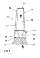
- a blade 10 of a gas turbine comprises an airfoil 14 with a leading edge 17 and a trailing edge 16.
- the airfoil 14 extends along a longitudinal axis X of said blade between a lower end and a blade tip 15.
- a blade root 12 is provided for being attached to a groove 31 in a rotor 11 of said gas turbine.
- a hollow blade core 18 is arranged within said airfoil 14 and extends along the longitudinal axis X between said blade root 12 and said blade tip 1.
- the blade core 18 is provided for the flow of a cooling fluid, which enters said blade core 18 through a blade inlet 20 at said blade root 12 and exits said blade core 18 through at least one dust hole (not shown in Fig. 1, 2 ) at said blade tip 15.
- the cooling fluid (cooling air) is supplied by means of a rotor bore 19, which runs through the rotor 11 and is in fluid communication with said blade inlet 20 of said blade 10.
- the direction of the rotor bore 19 is aligned with the blade orientation, i.e. the longitudinal axis X.
- a unique passage smoothly distributes the flow all over the cross section of the duct further above the blade inlet 20.
- the area/shape of the rotor bore exit 19, which is cylindrical, and the inlet 20 of the blade, which is race-track shaped, are different, leading to a noncontinuous interface (see Fig. 3 , the common area is shaded).
- a rotor bore is provided with a diffuser-shaped rotor bore exit, such that the cross section area of the rotor bore exit at the interface between rotor bore and blade inlet covers the cross section area of the blade inlet.
- an interface plenum is provided at the interface of said blade inlet and said rotor bore exit between the bottom surface of said blade root and the upper surface of said blade-root-receiving rotor groove, said interface plenum being designed to have a plenum bleed of cooling fluid to the outside of the blade root at the leading edge side or trailing edge side.
- said blade root has a blade root height h in longitudinal direction
- said blade core is split into a plurality of parallel cooling fluid ducts, wherein each of said cooling fluid ducts is in fluid communication with said blade inlet and has a dust hole at said blade tip, wherein a plurality of longitudinally extending not necessarily parallel webs is provided within said blade core for splitting said blade core into said plurality of cooling fluid ducts, and wherein, for an optimized cooling of said blade, an individual cross section area and an individual cooling fluid mass flow is associated with each of said plurality of cooling fluid ducts.
- said individual cross section areas and/or said individual cooling fluid mass flows of said cooling fluid ducts are equal within ⁇ 25%.
- said rotor bore is obliquely positioned in a axial plane with respect to said longitudinal axis of said blade, wherein the angle ⁇ of deviation between said rotor bore and said longitudinal axis is in the range 0° ⁇
- ⁇ 30°, and preferably ⁇ 13°.
- said diffuser-shaped rotor bore exit has a diffuser angle ⁇ , consisting of the angles ⁇ 1 and ⁇ 2 .
- the angular aperture of the both angles can be 7° ⁇ ⁇ 1 ⁇ 13°, and 7° ⁇ ⁇ 2 ⁇ 13°.
- an individual cross section area A 1 , A 2 , A 3 and an individual cooling fluid mass flow m 1 , m 2 , m 3 is associated with each of ducts 27a, 27b, 27c.
- the individual cross section areas A 1 , A 2 , A 3 and/or the individual cooling fluid mass flows m 1 , m 2 , m 3 of the ducts 27a, 27b, 27c are chosen to be equal with each other within ⁇ 25%.
- the rotor bore 23 is obliquely positioned in a axial plane with respect to the longitudinal axis X of the blade 10, 30, whereby the angle ⁇ of deviation between the rotor bore 23 and the longitudinal axis X is in the range 0° ⁇
- ⁇ 13°.
- the diffuser-shaped rotor bore exit 24 has a diffuser angles ⁇ 1 and ⁇ 2 .
- the angular aperture of the both angles can be 7° ⁇ ⁇ 1 ⁇ 13°, and 7° ⁇ ⁇ 2 ⁇ 13°.
- the blade root 12 has a blade root height h in longitudinal direction
Abstract
Description
- The present invention lies in the filed of gas turbines. It is related to gas turbines according to the preamble of claim 1.
- It is common practice to provide blades or vanes of gas turbines with some form of cooling in order to withstand the high temperatures of the hot gases flowing through such turbines. Typically, cooling ducts are provided within the airfoil of the blades or vanes, which are supplied in operation with pressurised cooling air derived from the compressor part of the gas turbine. Usually, the cooling ducts have the convoluted form of a serpentine, so that there is one flow of cooling fluid or cooling air passing through the airfoil in alternating and opposite directions. However, such a convoluted passageway necessarily requires bends, which give rise to pressure losses without heat transfer. Furthermore, as there is only one flow of cooling fluid, it is difficult to adapt this flow to the various cooling requirements existing at different locations of the airfoil.
- To achieve more flexibility in the cooling of the airfoil, it has been already proposed (
US-B2-6,874,992 ) to provide the airfoil with a plurality of cooling passages comprising a plurality of inlet passages along which cooling air flows from the base towards the tip region of the blade and a plurality of return passages along which cooling air flows from the tip towards the base region of the blade, whereby at least some of said inlet and return passages being connected by a common chamber located within the tip region of the blade. - However, as these known cooling passages are in fluid communication with each other by means of said common chamber located within the tip region of the blade, it is still difficult to adjust the individual mass flows of cooling fluid flowing through the various cooling passages.
- Another problem, which is related to the supply of the cooling fluid through the root of the blade or vane, may be explained with reference to
Fig. 1-3 : - According to
Fig. 1 ablade 10 of a gas turbine comprises anairfoil 14 with a leadingedge 17 and atrailing edge 16. Theairfoil 14 extends along a longitudinal axis X of said blade between a lower end and ablade tip 15. At the lower end of saidairfoil 14, ablade root 12 is provided for being attached to agroove 31 in arotor 11 of said gas turbine. Ahollow blade core 18 is arranged within saidairfoil 14 and extends along the longitudinal axis X between saidblade root 12 and said blade tip 1. Theblade core 18 is provided for the flow of a cooling fluid, which enters saidblade core 18 through ablade inlet 20 at saidblade root 12 and exits saidblade core 18 through at least one dust hole (not shown inFig. 1, 2 ) at saidblade tip 15. The cooling fluid (cooling air) is supplied by means of arotor bore 19, which runs through therotor 11 and is in fluid communication with saidblade inlet 20 of saidblade 10. - As shown in
Fig. 1 , the direction of therotor bore 19 is aligned with the blade orientation, i.e. the longitudinal axis X. A unique passage smoothly distributes the flow all over the cross section of the duct further above theblade inlet 20. However, the area/shape of the rotor boreexit 19, which is cylindrical, and theinlet 20 of the blade, which is race-track shaped, are different, leading to a noncontinuous interface (seeFig. 3 , the common area is shaded). - The consequences of this design are:
- (a) The flow accelerates through the relatively small common area between the exit of the rotor bore 19 and the
blade inlet 20. This produces flow separation near theblade inlet 20, leading to local low values of the internal heat transfer coefficient. Hot metal temperature regions may be detected further downstream of the blade. In addition, the pressure loss is increased. - (b) The orientation of the
rotor bore 19 is not flexible. If positioned inclined with respect to the blade (see rotor bore 19' inFig. 2 ), the flow separation area gets expanded and the situation worsens. This is particularly critical if the flow separation zone extends above theinner diameter platform 13 of the blade 10 (Fig. 2 ). - (c) Since the flow does not get uniform up to a height far enough from the
blade inlet 20, no webs can be positioned below theinner diameter platform 13. Therefore, this configuration does not allow to having a multi-pass design. - It is therefore an objective of the invention, to provide a gas turbine with a cooled blade, which allows for a flexible design and rating of the cooling passages, and especially allows for a multi-pass design.
- This objective is achieved by the measures according to the characterizing part of claim 1, i.e. a rotor bore is provided with a diffuser-shaped rotor bore exit, such that the cross section area of the rotor bore exit at the interface between rotor bore and blade inlet covers the cross section area of the blade inlet.
- According to one embodiment of the invention, an interface plenum is provided at the interface of said blade inlet and said rotor bore exit between the bottom surface of said blade root and the upper surface of said blade-root-receiving rotor groove, said interface plenum being designed to have a plenum bleed of cooling fluid to the outside of the blade root at the leading edge side or trailing edge side. Advantageously, said blade root has a blade root height h in longitudinal direction, and said interface plenum has a plenum gap δ with a ratio δ/h of 0.02 ≤ δ/h ≤ 0.05, and preferably δ/h = 0.03.
- According to another embodiment of the invention, said blade core is split into a plurality of parallel cooling fluid ducts, wherein each of said cooling fluid ducts is in fluid communication with said blade inlet and has a dust hole at said blade tip, wherein a plurality of longitudinally extending not necessarily parallel webs is provided within said blade core for splitting said blade core into said plurality of cooling fluid ducts, and wherein, for an optimized cooling of said blade, an individual cross section area and an individual cooling fluid mass flow is associated with each of said plurality of cooling fluid ducts. Advantageously, said individual cross section areas and/or said individual cooling fluid mass flows of said cooling fluid ducts are equal within ± 25%.
- According to still another embodiment of the invention, said rotor bore is obliquely positioned in a axial plane with respect to said longitudinal axis of said blade, wherein the angle β of deviation between said rotor bore and said longitudinal axis is in the range 0° < |β| ≤ 30°, and preferably β = 13°.
- According to still another embodiment of the invention, said diffuser-shaped rotor bore exit has a diffuser angle α, consisting of the angles α1 and α2. The diffuser can be symmetrical, for example α1 = 11° and α2 = 11°, or non-symmetrical as defined by α1 and α2. According to this the angular aperture of the both angles can be 7° ≤ α1 ≤ 13°, and 7° ≤ α2 ≤ 13°.
- According to still another embodiment of the invention, said blade root has a blade root height h in longitudinal direction, said blade inlet has a maximum width w, and the ratio h/w is 2.0 ≤ h/w ≤ 3.5, preferably h/w = 2.5.
- The subject matter of the invention will be explained in more detail in the following text with reference to preferred exemplary embodiments, which are illustrated in the attached drawings, in which:
- Fig. 1
- shows a side view of a cooled rotor blade according to a first embodiment of a previous blade with a longitudinally extending rotor bore;
- Fig. 2
- shows a side view of a cooled rotor blade according to a second embodiment of a previous blade with an obliquely oriented rotor bore;
- Fig. 3
- shows the mismatch between the rotor bore exit and the blade inlet in a previous blade according to
Fig. 1 or 2 ; - Fig. 4
- shows a side view of a cooled rotor blade according to an embodiment of the invention with an obliquely oriented rotor bore comprising a diffuser-shaped rotor bore exit;
- Fig. 5
- shows in a side view a detail of the blade tip of a blade according to a second embodiment of the invention wit a plurality of individually adjustable parallel cooling ducts;
- Fig. 5a
- Flow cross section of
Fig. 5 and - Fig. 6
- shows in a side view a detail of the blade root of the blade according to
Fig. 5 with an bleeding interface plenum at the interface between the blade root and the bottom of the root-receiving rotor groove, including a focusing figure of the diffuser with the both angles α1 and α2. - According to the invention several measures are taken (
Fig. 4-6 ), that substantially contribute to solve the problems/limitations described above: - (a) An interface plenum 28 (
Fig. 6 ) is created underneath theblade inlet 20 of theblade 30 by leaving some gap δ between the rotor upper surface in therotor groove 23 and the bottom surface of theblade root 12, confined by the fir-tree of therotor 11. - (b) The
rotor bore exit 24 is reworked with a diffuser-shaped (conical) form extending over the whole width w of theblade inlet 20. - (c) A part of the cooling fluid flow is conveniently bled from the leading edge side (17) or trailing edge side (16) of the plenum slot (28).
- Both the
interface plenum 28 and the diffuser-shaped rotor boreexit 24 acting to decelerate the cooling fluid flow and to extend it along the whole width w of theblade inlet 20. The bleeding flow from theinterface plenum slot 28 supports this task (especially if the rotor bore 23 is inclined). - The benefits of this configuration are:
- (a) By the time the coolant reaches the inlet section of the
blade 10, flow conditions are quite even all over the cross-section of theblade inlet 20.
The coolant is therefore better distributed across the entire cross-section of theblade 30, mitigating or cancelling the presence of flow separation (Fig. 4 ). If flow separation still exists, it is confined well below theinner diameter platform 13 anyway, even for quite short shanks. - (b) Inlet pressure losses are reduced.
- (c) The stream manages to quickly adapt to the orientation of the
blade 10 regardless of the feed direction of the rotor bore 23. As a consequence, the invention allows inclining the rotor bore 23 feeding theblade 10 if the rotor design requires so (Fig. 4 ). - (d) Further, as the feed coolant conditions are already quite uniform sufficiently below the
inner diameter platform 13, the invention allows the introduction ofwebs blade 30 inFig. 5, 6 ). In particular, a 3-pass design with twowebs parallel ducts 27a, 27b and 27c is chosen as best compromise between cooling effectiveness and weight. Such a design is more effective than the current unique passage design, because it allows a better control of the local mass flow m1, m2, and m3 through theentire core section 18.
The control of the flow split through each of theducts 27a, 27b and 27c is done with dust holes positioned at the blade tip 15 (see arrows at the blade tip inFig. 5 ), which can be size-customized independently. This design adds in addition cold material to the cross-section to successfully carry a blade shroud if required. - (e) All benefits mentioned above are managed with very little change/redesign of the blade.
- For an optimized cooling of the 3-
pass blade 30 inFig. 5, 6 an individual cross section area A1, A2, A3 and an individual cooling fluid mass flow m1, m2, m3 is associated with each ofducts 27a, 27b, 27c. Favourably, the individual cross section areas A1, A2, A3 and/or the individual cooling fluid mass flows m1, m2, m3 of theducts 27a, 27b, 27c are chosen to be equal with each other within ± 25%. - Furthermore it is advantageous that the rotor bore 23 is obliquely positioned in a axial plane with respect to the longitudinal axis X of the
blade - It is also advantageous, that the diffuser-shaped rotor bore
exit 24 has a diffuser angles α1 and α2. The diffuser can be symmetrical, for example α1 = 11° and α2 = 11°, or non-symmetrical as defined by α1 and α2. According to this the angular aperture of the both angles can be 7° ≤ α1 ≤ 13°, and 7° ≤ α2 ≤ 13°. - Preferably, the
blade root 12 has a blade root height h in longitudinal direction, and theinterface plenum 28 has a plenum gap δ, such that the ratio δ/h is in the range of 0.02 ≤ δ/h ≤ 0.05, and preferably δ/h = 0.03. This leads to a plenum bleed flow mb, which is a fixed part of the cooling supply flow ms with a ratio of mb/ ms = 0.2 ± 20%. - Finally, the
blade root 12 has a blade root height h in longitudinal direction, and theblade inlet 20 has a maximum width w, and the ratio h/w lies in the range 2.0 ≤ h/w ≤ 3.5, and is preferably h/w = 2.5. -
- 10,30
- Blade (gas turbine)
- 11
- Rotor
- 12
- Blade root
- 13
- Platform (inner diameter)
- 14
- Airfoil
- 15
- Blade tip
- 16
- Trailing edge
- 17
- Leading edge
- 18
- Blade core
- 19,19',23
- Rotor bore
- 20
- Blade inlet
- 21
- Pressure side
- 22
- Suction side
- 24
- Rotor bore exit (diffuser shaped)
- 25,26
- Web
- 27a,b,c
- Duct
- 28
- Interface plenum
- 29
- Plenum bleed
- 31
- Rotor groove
- α
- Diffuser angle made up of α1 and α2.
- α1, α2
- Diffuser angles
- β
- Angle of deviation
- δ
- Plenum gap
- h
- Blade root height
- w
- Maximum width
- X
- Longitudinal axis
- A1,A2,A3
- Cross section area
- m1,m2,m3
- Mass flow
- mb
- Plenum bleed flow
- ms
- Cooling supply flow
Claims (14)
- Gas turbine with a rotor (11) and a blade (10, 30) being attached to said rotor (11), wherein said blade (10, 30) comprises an airfoil (14) with a leading edge (17) and a trailing edge (16) extending along a longitudinal axis (X) of said blade (30) between a lower end and a blade tip (15), a blade root (12) at the lower end of said airfoil (14) provided for being removably received by a groove (31) in said rotor (11), and a hollow blade core (18) arranged within said airfoil (14) and extending along the longitudinal axis (X) between said blade root (12) and said blade tip (15), said blade core (18) being provided for the flow of a cooling fluid, which enters said blade core (18) through a blade inlet (20) at said blade root (12) and exits said blade core (18) through at least one dust hole at said blade tip (15), and is supplied by means of a rotor bore (23), which runs through the rotor (11) and is in fluid communication with said blade inlet (20) of said blade, whereby said blade inlet (20) has a cross section area which exceeds the cross section area of said rotor bore (23) in at least one direction, characterized in that said rotor bore (23) is provided with a diffuser-shaped rotor bore exit (24), such that the cross section area of the rotor bore exit (24) at the interface between rotor bore (23) and blade inlet (20) covers the cross section area of the blade inlet (20).
- Gas turbine according to claim 1, characterized in that an interface plenum (28) is provided at the interface of said blade inlet (20) and said rotor bore exit (24) between the bottom surface of said blade root (12) and the upper surface of said blade-root-receiving rotor groove (31).
- Gas turbine according to claim 2, characterized in that said interface plenum (28) is designed to have a plenum bleed (29) of cooling fluid to the outside of the blade root (12) at the leading edge side or trailing edge side.
- Gas turbine according to one of the claims 1 to 3, characterized in that said blade core (18) is split into a plurality of parallel cooling fluid ducts (27a, 27b, 27c), wherein each of said cooling fluid ducts (27a, 27b, 27c) is in fluid communication with said blade inlet (20) and has a number of dust holes at said blade tip (15).
- Gas turbine according to claim 4, characterized in that each cooling fluid ducts (27a, 27b, 27c) has at least a dust hole at said blade tip (15).
- Gas turbine according to claim 4, characterized in that a plurality of longitudinally extending parallel webs (25, 26) is provided within said blade core (18) for splitting said blade core (18) into said plurality of cooling fluid ducts (27a, 27b, 27c).
- Gas turbine according to claim 4 or 5 or 6, characterized in that, for an optimized cooling of said blade, an individual flow cross section area (A1, A2, A3) and an individual cooling fluid mass flow (m1, m2, m3) is associated with each of said plurality of cooling fluid ducts (27a, 27b, 27c).
- Gas turbine according to claim 7, characterized in that the flow cross section area (A1) is a cross-sectional area of passage which is normal to direction of the flow.
- Gas turbine according to one of the claims 1 to 8, characterized in that said rotor bore (23) is obliquely positioned in an axial plane with respect to said longitudinal axis (X) of said blade (30).
- Gas turbine according to claim 9, characterized in that the angle β of deviation between said rotor bore (23) and said longitudinal axis (X) is in the range 0° < |β| ≤ 30°, and preferably β = 13°.
- Gas turbine according to one of the claims 1 to 10, characterized in that said diffuser-shaped rotor bore exit (24) has a diffuser angles (α1, α2), whereas the diffuser is symmetric or non symmetric, with an angular aperture of the both angles of 7° ≤ α1 ≤ 13°, and 7° ≤ α2 ≤ 13°.
- Gas turbine according to claim 2, characterized in that said blade root (12) has a blade root height h in longitudinal direction, and said interface plenum (28) has a plenum gap δ with a ratio δ/h of 0.02 ≤ δ/h ≤ 0.05, and preferably δ/h = 0.03.
- Gas turbine according to one of the claims 1 to 12, characterized in that said blade root (12) has a blade root height h in longitudinal direction, said blade inlet (20) has a width w, and the ratio h/w is 2.0 ≤ h/w ≤ 3.5, preferably h/w = 2.5.
- Gas turbine according to claim 7, characterized in that said individual cross section areas (A1, A2, A3) and/or said individual cooling fluid mass flows (m1, m2, m3) of said cooling fluid ducts (27a, 27b, 27c) are equal within ± 25%.
Priority Applications (8)
| Application Number | Priority Date | Filing Date | Title |
|---|---|---|---|
| EP09155854A EP2236746A1 (en) | 2009-03-23 | 2009-03-23 | Gas turbine |
| PCT/EP2010/053670 WO2010108879A1 (en) | 2009-03-23 | 2010-03-22 | Gas turbine |
| MX2011009617A MX340308B (en) | 2009-03-23 | 2010-03-22 | Gas turbine. |
| EP10710027.3A EP2411629B1 (en) | 2009-03-23 | 2010-03-22 | Gas turbine |
| RU2011142732/06A RU2531839C2 (en) | 2009-03-23 | 2010-03-22 | Gas turbine |
| SG2011068152A SG174494A1 (en) | 2009-03-23 | 2010-03-22 | Gas turbine |
| KR1020117022161A KR101613866B1 (en) | 2009-03-23 | 2010-03-22 | Gas turbine |
| US13/239,549 US9341069B2 (en) | 2009-03-23 | 2011-09-22 | Gas turbine |
Applications Claiming Priority (1)
| Application Number | Priority Date | Filing Date | Title |
|---|---|---|---|
| EP09155854A EP2236746A1 (en) | 2009-03-23 | 2009-03-23 | Gas turbine |
Publications (1)
| Publication Number | Publication Date |
|---|---|
| EP2236746A1 true EP2236746A1 (en) | 2010-10-06 |
Family
ID=40875154
Family Applications (2)
| Application Number | Title | Priority Date | Filing Date |
|---|---|---|---|
| EP09155854A Withdrawn EP2236746A1 (en) | 2009-03-23 | 2009-03-23 | Gas turbine |
| EP10710027.3A Active EP2411629B1 (en) | 2009-03-23 | 2010-03-22 | Gas turbine |
Family Applications After (1)
| Application Number | Title | Priority Date | Filing Date |
|---|---|---|---|
| EP10710027.3A Active EP2411629B1 (en) | 2009-03-23 | 2010-03-22 | Gas turbine |
Country Status (7)
| Country | Link |
|---|---|
| US (1) | US9341069B2 (en) |
| EP (2) | EP2236746A1 (en) |
| KR (1) | KR101613866B1 (en) |
| MX (1) | MX340308B (en) |
| RU (1) | RU2531839C2 (en) |
| SG (1) | SG174494A1 (en) |
| WO (1) | WO2010108879A1 (en) |
Cited By (3)
| Publication number | Priority date | Publication date | Assignee | Title |
|---|---|---|---|---|
| CH704716A1 (en) * | 2011-03-22 | 2012-09-28 | Alstom Technology Ltd | Rotor disk for a turbine rotor and turbine as well as with such a rotor disk. |
| EP2535515A1 (en) * | 2011-06-16 | 2012-12-19 | Siemens Aktiengesellschaft | Rotor blade root section with cooling passage and method for supplying cooling fluid to a rotor blade |
| EP3336313A1 (en) * | 2016-12-19 | 2018-06-20 | Rolls-Royce Deutschland Ltd & Co KG | Turbine rotor blade arrangement for a gas turbine and method for the provision of sealing air in a turbine rotor blade arrangement |
Families Citing this family (6)
| Publication number | Priority date | Publication date | Assignee | Title |
|---|---|---|---|---|
| EP2725191B1 (en) | 2012-10-23 | 2016-03-16 | Alstom Technology Ltd | Gas turbine and turbine blade for such a gas turbine |
| EP3080400B1 (en) | 2013-12-12 | 2019-04-10 | United Technologies Corporation | Gas turbine engine rotor and corresponding method of cooling |
| EP3059394B1 (en) * | 2015-02-18 | 2019-10-30 | Ansaldo Energia Switzerland AG | Turbine blade and set of turbine blades |
| US11073024B2 (en) | 2018-12-14 | 2021-07-27 | Raytheon Technologies Corporation | Shape recessed surface cooling air feed hole blockage preventer for a gas turbine engine |
| US11008872B2 (en) | 2018-12-14 | 2021-05-18 | Raytheon Technologies Corporation | Extension air feed hole blockage preventer for a gas turbine engine |
| US11078796B2 (en) | 2018-12-14 | 2021-08-03 | Raytheon Technologies Corporation | Redundant entry cooling air feed hole blockage preventer for a gas turbine engine |
Citations (8)
| Publication number | Priority date | Publication date | Assignee | Title |
|---|---|---|---|---|
| GB611044A (en) * | 1944-03-03 | 1948-10-25 | Rateau Soc | Improvements in or relating to wheels of turbines and the like machines |
| US2657902A (en) * | 1947-12-17 | 1953-11-03 | Packard Motor Car Co | Turbine rotor for turbojet engines |
| GB868788A (en) * | 1956-11-20 | 1961-05-25 | Robert Pouit | Improvements in gas turbine installations |
| FR2152437A1 (en) * | 1971-09-15 | 1973-04-27 | Snecma | |
| US3749514A (en) * | 1971-09-30 | 1973-07-31 | United Aircraft Corp | Blade attachment |
| JPS5951103A (en) * | 1982-09-20 | 1984-03-24 | Fuji Electric Co Ltd | Cooling device of turbine moving blade and disk |
| EP1041246A1 (en) * | 1999-03-29 | 2000-10-04 | Siemens Aktiengesellschaft | Casted gas turbine blade with inner cooling, method and device for manufacturing a manifold of the gas turbine blade |
| US6874992B2 (en) | 2001-11-27 | 2005-04-05 | Rolls-Royce Plc | Gas turbine engine aerofoil |
Family Cites Families (20)
| Publication number | Priority date | Publication date | Assignee | Title |
|---|---|---|---|---|
| US2648520A (en) * | 1949-08-02 | 1953-08-11 | Heinz E Schmitt | Air-cooled turbine blade |
| US2951340A (en) * | 1956-01-03 | 1960-09-06 | Curtiss Wright Corp | Gas turbine with control mechanism for turbine cooling air |
| US3370830A (en) * | 1966-12-12 | 1968-02-27 | Gen Motors Corp | Turbine cooling |
| US3918835A (en) * | 1974-12-19 | 1975-11-11 | United Technologies Corp | Centrifugal cooling air filter |
| US4017209A (en) * | 1975-12-15 | 1977-04-12 | United Technologies Corporation | Turbine rotor construction |
| GB1551678A (en) * | 1978-03-20 | 1979-08-30 | Rolls Royce | Cooled rotor blade for a gas turbine engine |
| US4344738A (en) * | 1979-12-17 | 1982-08-17 | United Technologies Corporation | Rotor disk structure |
| US4501053A (en) * | 1982-06-14 | 1985-02-26 | United Technologies Corporation | Method of making rotor blade for a rotary machine |
| US4820123A (en) * | 1988-04-25 | 1989-04-11 | United Technologies Corporation | Dirt removal means for air cooled blades |
| US4820122A (en) * | 1988-04-25 | 1989-04-11 | United Technologies Corporation | Dirt removal means for air cooled blades |
| US5503527A (en) | 1994-12-19 | 1996-04-02 | General Electric Company | Turbine blade having tip slot |
| GB9615394D0 (en) * | 1996-07-23 | 1996-09-04 | Rolls Royce Plc | Gas turbine engine rotor disc with cooling fluid passage |
| DE10064269A1 (en) | 2000-12-22 | 2002-07-04 | Alstom Switzerland Ltd | Component of a turbomachine with an inspection opening |
| US6735956B2 (en) * | 2001-10-26 | 2004-05-18 | Pratt & Whitney Canada Corp. | High pressure turbine blade cooling scoop |
| DE10331635B4 (en) * | 2003-07-12 | 2014-02-13 | Alstom Technology Ltd. | Cooled shovel for a gas turbine |
| US7059825B2 (en) * | 2004-05-27 | 2006-06-13 | United Technologies Corporation | Cooled rotor blade |
| US7097419B2 (en) * | 2004-07-26 | 2006-08-29 | General Electric Company | Common tip chamber blade |
| US7632071B2 (en) * | 2005-12-15 | 2009-12-15 | United Technologies Corporation | Cooled turbine blade |
| RU2323343C2 (en) * | 2006-03-20 | 2008-04-27 | Федеральное государственное унитарное предприятие "Московское машиностроительное производственное предприятие "САЛЮТ" (ФГУП "ММПП "САЛЮТ") | Turbomachine cooled blade |
| US7762774B2 (en) * | 2006-12-15 | 2010-07-27 | Siemens Energy, Inc. | Cooling arrangement for a tapered turbine blade |
-
2009
- 2009-03-23 EP EP09155854A patent/EP2236746A1/en not_active Withdrawn
-
2010
- 2010-03-22 KR KR1020117022161A patent/KR101613866B1/en not_active IP Right Cessation
- 2010-03-22 EP EP10710027.3A patent/EP2411629B1/en active Active
- 2010-03-22 SG SG2011068152A patent/SG174494A1/en unknown
- 2010-03-22 RU RU2011142732/06A patent/RU2531839C2/en active
- 2010-03-22 MX MX2011009617A patent/MX340308B/en active IP Right Grant
- 2010-03-22 WO PCT/EP2010/053670 patent/WO2010108879A1/en active Application Filing
-
2011
- 2011-09-22 US US13/239,549 patent/US9341069B2/en not_active Expired - Fee Related
Patent Citations (8)
| Publication number | Priority date | Publication date | Assignee | Title |
|---|---|---|---|---|
| GB611044A (en) * | 1944-03-03 | 1948-10-25 | Rateau Soc | Improvements in or relating to wheels of turbines and the like machines |
| US2657902A (en) * | 1947-12-17 | 1953-11-03 | Packard Motor Car Co | Turbine rotor for turbojet engines |
| GB868788A (en) * | 1956-11-20 | 1961-05-25 | Robert Pouit | Improvements in gas turbine installations |
| FR2152437A1 (en) * | 1971-09-15 | 1973-04-27 | Snecma | |
| US3749514A (en) * | 1971-09-30 | 1973-07-31 | United Aircraft Corp | Blade attachment |
| JPS5951103A (en) * | 1982-09-20 | 1984-03-24 | Fuji Electric Co Ltd | Cooling device of turbine moving blade and disk |
| EP1041246A1 (en) * | 1999-03-29 | 2000-10-04 | Siemens Aktiengesellschaft | Casted gas turbine blade with inner cooling, method and device for manufacturing a manifold of the gas turbine blade |
| US6874992B2 (en) | 2001-11-27 | 2005-04-05 | Rolls-Royce Plc | Gas turbine engine aerofoil |
Cited By (5)
| Publication number | Priority date | Publication date | Assignee | Title |
|---|---|---|---|---|
| CH704716A1 (en) * | 2011-03-22 | 2012-09-28 | Alstom Technology Ltd | Rotor disk for a turbine rotor and turbine as well as with such a rotor disk. |
| EP2535515A1 (en) * | 2011-06-16 | 2012-12-19 | Siemens Aktiengesellschaft | Rotor blade root section with cooling passage and method for supplying cooling fluid to a rotor blade |
| US9664051B2 (en) | 2011-06-16 | 2017-05-30 | Siemens Aktiengesellschaft | Rotor blade root section with cooling passage and method for supplying cooling fluid to a rotor blade |
| EP3336313A1 (en) * | 2016-12-19 | 2018-06-20 | Rolls-Royce Deutschland Ltd & Co KG | Turbine rotor blade arrangement for a gas turbine and method for the provision of sealing air in a turbine rotor blade arrangement |
| US10619490B2 (en) | 2016-12-19 | 2020-04-14 | Rolls-Royce Deutschland Ltd & Co Kg | Turbine rotor blade arrangement for a gas turbine and method for the provision of sealing air in a turbine rotor blade arrangement |
Also Published As
| Publication number | Publication date |
|---|---|
| MX340308B (en) | 2016-07-05 |
| WO2010108879A1 (en) | 2010-09-30 |
| EP2411629A1 (en) | 2012-02-01 |
| RU2531839C2 (en) | 2014-10-27 |
| KR101613866B1 (en) | 2016-04-20 |
| RU2011142732A (en) | 2013-04-27 |
| MX2011009617A (en) | 2011-09-29 |
| EP2411629B1 (en) | 2018-03-07 |
| SG174494A1 (en) | 2011-10-28 |
| US20120087782A1 (en) | 2012-04-12 |
| KR20120005444A (en) | 2012-01-16 |
| US9341069B2 (en) | 2016-05-17 |
Similar Documents
| Publication | Publication Date | Title |
|---|---|---|
| EP2411629B1 (en) | Gas turbine | |
| EP1561902B1 (en) | Turbine blade comprising turbulation promotion devices | |
| US7887294B1 (en) | Turbine airfoil with continuous curved diffusion film holes | |
| EP2564028B1 (en) | Gas turbine blade | |
| EP2728117B1 (en) | Turbine blade tip with tip shelf diffuser holes | |
| EP1091092B1 (en) | Coolable gas turbine airfoil | |
| EP2564029B1 (en) | Gas turbine blade | |
| JP5503140B2 (en) | Divergent turbine nozzle | |
| EP2682565B1 (en) | Cooled blade for a gas turbine | |
| US20100226788A1 (en) | Turbine blade with incremental serpentine cooling channels beneath a thermal skin | |
| EP1826361B1 (en) | Gas turbine engine aerofoil | |
| EP1865152B1 (en) | Cooling microcircuits for turbine airfoils | |
| US7762775B1 (en) | Turbine airfoil with cooled thin trailing edge | |
| EP2615245B1 (en) | Film cooled turbine airfoil having trench segments on the exterior surface | |
| EP2847435B1 (en) | Convective heat removal cooling hole pattern | |
| US10648342B2 (en) | Engine component with cooling hole | |
| EP1561903B1 (en) | Tailored turbulation for turbine blades | |
| US20220145764A1 (en) | Component for a turbine engine with a cooling hole | |
| CN107143382B (en) | CMC article with small complex features for advanced film cooling | |
| EP1538305B1 (en) | Airfoil with variable density array of pedestals at the trailing edge | |
| CN109083688B (en) | Turbine engine component with deflector | |
| US10570773B2 (en) | Turbine shroud cooling | |
| EP3669054B1 (en) | Turbine blade and corresponding method of servicing | |
| EP2180141A1 (en) | Cooled blade for a gas turbine, method for producing such a blade, and gas turbine having such a blade | |
| US20170122112A1 (en) | Controlling cooling flow in a cooled turbine vane or blade using an impingement tube |
Legal Events
| Date | Code | Title | Description |
|---|---|---|---|
| PUAI | Public reference made under article 153(3) epc to a published international application that has entered the european phase |
Free format text: ORIGINAL CODE: 0009012 |
|
| AK | Designated contracting states |
Kind code of ref document: A1 Designated state(s): AT BE BG CH CY CZ DE DK EE ES FI FR GB GR HR HU IE IS IT LI LT LU LV MC MK MT NL NO PL PT RO SE SI SK TR |
|
| AX | Request for extension of the european patent |
Extension state: AL BA RS |
|
| AKY | No designation fees paid | ||
| REG | Reference to a national code |
Ref country code: DE Ref legal event code: R108 Effective date: 20110526 |
|
| STAA | Information on the status of an ep patent application or granted ep patent |
Free format text: STATUS: THE APPLICATION IS DEEMED TO BE WITHDRAWN |
|
| 18D | Application deemed to be withdrawn |
Effective date: 20110407 |