EP2728117B1 - Turbine blade tip with tip shelf diffuser holes - Google Patents
Turbine blade tip with tip shelf diffuser holes Download PDFInfo
- Publication number
- EP2728117B1 EP2728117B1 EP13190436.9A EP13190436A EP2728117B1 EP 2728117 B1 EP2728117 B1 EP 2728117B1 EP 13190436 A EP13190436 A EP 13190436A EP 2728117 B1 EP2728117 B1 EP 2728117B1
- Authority
- EP
- European Patent Office
- Prior art keywords
- tip
- diffuser
- cooling
- shelf
- airfoil
- Prior art date
- Legal status (The legal status is an assumption and is not a legal conclusion. Google has not performed a legal analysis and makes no representation as to the accuracy of the status listed.)
- Active
Links
- 238000001816 cooling Methods 0.000 claims description 78
- 239000000112 cooling gas Substances 0.000 claims description 19
- 239000000567 combustion gas Substances 0.000 claims description 10
- 230000005465 channeling Effects 0.000 claims description 6
- 238000004891 communication Methods 0.000 claims description 4
- 238000011144 upstream manufacturing Methods 0.000 claims description 2
- 239000007789 gas Substances 0.000 description 14
- 230000007423 decrease Effects 0.000 description 7
- 238000002485 combustion reaction Methods 0.000 description 5
- 238000013461 design Methods 0.000 description 5
- 238000013459 approach Methods 0.000 description 4
- 230000008901 benefit Effects 0.000 description 2
- 238000009792 diffusion process Methods 0.000 description 2
- 230000009429 distress Effects 0.000 description 2
- 230000003628 erosive effect Effects 0.000 description 2
- 230000004907 flux Effects 0.000 description 2
- 230000001965 increasing effect Effects 0.000 description 2
- 238000000034 method Methods 0.000 description 2
- 230000003647 oxidation Effects 0.000 description 2
- 238000007254 oxidation reaction Methods 0.000 description 2
- 230000036961 partial effect Effects 0.000 description 2
- 230000002411 adverse Effects 0.000 description 1
- 239000002826 coolant Substances 0.000 description 1
- 230000000254 damaging effect Effects 0.000 description 1
- 230000003247 decreasing effect Effects 0.000 description 1
- 230000001627 detrimental effect Effects 0.000 description 1
- 230000000694 effects Effects 0.000 description 1
- 230000002708 enhancing effect Effects 0.000 description 1
- 239000000284 extract Substances 0.000 description 1
- 238000000605 extraction Methods 0.000 description 1
- 238000007373 indentation Methods 0.000 description 1
- 230000002829 reductive effect Effects 0.000 description 1
- 238000000926 separation method Methods 0.000 description 1
- 238000012546 transfer Methods 0.000 description 1
- 230000007704 transition Effects 0.000 description 1
Images


Classifications
-
- F—MECHANICAL ENGINEERING; LIGHTING; HEATING; WEAPONS; BLASTING
- F01—MACHINES OR ENGINES IN GENERAL; ENGINE PLANTS IN GENERAL; STEAM ENGINES
- F01D—NON-POSITIVE DISPLACEMENT MACHINES OR ENGINES, e.g. STEAM TURBINES
- F01D5/00—Blades; Blade-carrying members; Heating, heat-insulating, cooling or antivibration means on the blades or the members
- F01D5/12—Blades
- F01D5/14—Form or construction
- F01D5/18—Hollow blades, i.e. blades with cooling or heating channels or cavities; Heating, heat-insulating or cooling means on blades
- F01D5/186—Film cooling
-
- F—MECHANICAL ENGINEERING; LIGHTING; HEATING; WEAPONS; BLASTING
- F01—MACHINES OR ENGINES IN GENERAL; ENGINE PLANTS IN GENERAL; STEAM ENGINES
- F01D—NON-POSITIVE DISPLACEMENT MACHINES OR ENGINES, e.g. STEAM TURBINES
- F01D5/00—Blades; Blade-carrying members; Heating, heat-insulating, cooling or antivibration means on the blades or the members
- F01D5/12—Blades
- F01D5/14—Form or construction
- F01D5/18—Hollow blades, i.e. blades with cooling or heating channels or cavities; Heating, heat-insulating or cooling means on blades
- F01D5/187—Convection cooling
-
- F—MECHANICAL ENGINEERING; LIGHTING; HEATING; WEAPONS; BLASTING
- F01—MACHINES OR ENGINES IN GENERAL; ENGINE PLANTS IN GENERAL; STEAM ENGINES
- F01D—NON-POSITIVE DISPLACEMENT MACHINES OR ENGINES, e.g. STEAM TURBINES
- F01D5/00—Blades; Blade-carrying members; Heating, heat-insulating, cooling or antivibration means on the blades or the members
- F01D5/12—Blades
- F01D5/14—Form or construction
- F01D5/20—Specially-shaped blade tips to seal space between tips and stator
-
- F—MECHANICAL ENGINEERING; LIGHTING; HEATING; WEAPONS; BLASTING
- F05—INDEXING SCHEMES RELATING TO ENGINES OR PUMPS IN VARIOUS SUBCLASSES OF CLASSES F01-F04
- F05D—INDEXING SCHEME FOR ASPECTS RELATING TO NON-POSITIVE-DISPLACEMENT MACHINES OR ENGINES, GAS-TURBINES OR JET-PROPULSION PLANTS
- F05D2260/00—Function
- F05D2260/20—Heat transfer, e.g. cooling
- F05D2260/202—Heat transfer, e.g. cooling by film cooling
Definitions
- the present disclosure relates generally to gas turbine engines, and, more specifically, to a turbine blade assembly having improved tip cooling.
- a gas turbine engine includes one or more turbine blade rows disposed downstream of a combustor which extracts energy from combustion gases generated by the combustor. Disposed radially outwardly of the rotor blade tips may be a stator shroud which is spaced from the blade tips to provide a relatively small clearance between the blade tips and shroud for reducing leakage of the combustion gases over the blade tips during operation.
- Each of the rotor blades includes conventionally known pressure and suction sides which are preferentially aerodynamically contoured for extracting as much energy as possible from the combustion gases flowing over the rotor blades. The pressure and suction sides extend to the blade tip and are disposed as close as possible to the stator shroud for maximizing the amount of energy extracted from the combustion gases.
- the clearance, however, between the blade tips and the stator shroud must nevertheless be adequate to minimize the occurrence of blade tip rubs during operation, which may damage the blade tips.
- Un-shrouded blades use a squealer tip to reduce hot gas leakage over the blade tip and reduce performance penalties.
- a tip design typically requires ribs, generally a pressure side rib and a suction side rib, to protrude from the blade tip floor. These ribs are relatively thin, which makes them difficult to cool effectively through conduction. Turbine blade tips and associated ribs, moreover, are exposed to the very high temperatures of combustion gasses flowing over their outside surfaces. These high temperatures and low cooling effectiveness lead to durability issues on the tip ribs and the potential for blade fallout at the end of the blade's life interval. Any tip ribs that suffer oxidation or cracks beyond the squealer floor will render a blade irreparable regardless of the overall airfoil condition.
- turbine rotor blades are typically hollow for channeling cooling air through the interior of the blade.
- This cooling air is provided from a conventional compressor of the gas turbine engine to cool the blades from the heat flux generated by the combustion gases flowing over the blades.
- the tip, or tip cap, portion of the blades is particularly susceptible to the damaging effects of the hot combustion gases and must be suitably cooled for reducing blade tip distress in the form of oxidation and thermal fatigue during operation.
- the pressure and/or suction sides of the blade are adversely affected, which decreases the aerodynamic efficiency of the blade used for extracting energy from the combustion gases.
- such erosion of the blade tip also increases the clearance between the blade tip and the stator shroud, which allows more of the combustion gases to leak over the blade tip, and, therefore, extraction of the energy therefrom is lost which also decreases aerodynamic efficiency.
- Conventional design practice makes use of a tip shelf recess or an L-shaped trough defined by the tip shelf and a first tip wall disposed on the pressure side of the blade.
- the tip shelf may offer the advantage of providing a discontinuity on the airfoil pressure side of the blade tip, causing combustion gasses to separate from the surface of the blade tip, which may decreases the heat transfer capability of the hot gasses to the blade tip, and therefore may decrease the heat flux into the blade tip.
- EP 1059419 discloses a turbine airfoil including cooling gas feed holes in the tip floor, and various tip arrangements.
- cooling the blade tip is to increase the total number of straight round cooling holes in the tip shelf to increase the total cooling flow and decrease the space available for hot gas to interact with the surface. Since cooling of the blade, including the blade tip, uses a portion of the compressed air from the gas turbine compressor, however, that air is unavailable for combustion in the combustor of the engine which decreases the overall efficiency of the gas turbine engine. Accordingly, cooling of the blade, including the blade tip, should be accomplished with as little compressed air as possible to minimize the loss in gas turbine engine efficiency.
- Still another approach involves creating channels or indentations in the pressure side rib to direct cooling flow from the pressure side tip holes over the rim at desired locations to better cover the surface.
- a turbine blade assembly according to claim 1.
- Diffuser cooling holes allow the cooling gas to begin diffusing before exiting the cooling hole and covering a larger area than a straight hole would provide.
- the diffused cooling gas flows over the pressure side rail covering a larger surface area than is typical using straight round cooling holes. This increased coverage provides more even cooling to the pressure side rail and less near-surface leakage paths for hot gas to occupy.
- the cooling gas diffusion also serves to reduce the coolant exit velocity into the tip shelf cavity. The reduced velocity increases the amount of cooling gas that is entrained in the shelf, thereby enhancing the overall cooling into the pressure side rail from the tip shelf region.
- Gas turbine blades having a cooling channel therein for channeling cooling air to the tip of the blade are generally known.
- the turbine blades typically include an airfoil including a first side joined to a second side at spaced apart leading and trailing edges to define therein a flow channel for channeling cooling air through the airfoil to cool the airfoil from combustion gases flowing over the first and second sides.
- the airfoil typically has a tip at its distal end and a root having a dovetail extending from the root for mounting the blade to a rotor disk.
- the airfoil tip typically includes a tip floor extending between the airfoil first and second sides and between the leading and trailing edges for enclosing the airfoil for containing cooling air in the air flow channel.
- a first tip wall typically extends from the tip floor at the airfoil first side to form an extension thereof.
- a second tip wall typically extends from the tip floor at the airfoil second side to form an extension thereof, and is spaced in part from the first tip wall to define therebetween an outwardly facing tip plenum.
- the first tip wall is typically recessed at least in part from the airfoil first side to define an outwardly facing tip shelf extending between the leading and trailing edges to provide a discontinuity in the airfoil first side, the first tip wall and the tip shelf defining therebetween a tip shelf recess or trough.
- the tip shelf may extend from the leading edge to a point short of the trailing edge, a configuration sometimes referred to as a "partial tip shelf.”
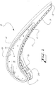
- FIGS. 1 , 2 , and 8 there is shown a portion of a turbine blade squealer tip, generally 10, of an embodiment of the present invention.
- the squealer tip 10 is located at the distal end of a turbine blade assembly.
- the turbine blade assembly may have at its proximal end an airfoil root for mounting the blade to a rotor disc of a gas turbine engine.
- the blade assembly and squealer tip 10 have along their length between the airfoil root and the blade tip a leading edge 11 that transitions to a tapered trailing edge 12.
- the blade assembly and squealer tip further have along its width between the leading edge 11 and trailing edge 12 a first wall 13 on the pressure side of the assembly, and a second wall 14 on the suction side of the assembly opposite the first wall 13.
- the first wall 13 has a generally concave shape and has disposed thereon a tip shelf, sometimes referred to as a butt shelf or bucket tip shelf, 15, that runs substantially from the leading edge 11 to the trailing edge 12.
- the second wall 14 has a substantially convex shape.
- the tip shelf 15 is formed in a squealer tip rim 16 that is positioned at the blade tip.
- the tip shelf 15 has positioned therealong one or more diffuser cooling holes 17.
- the tip floor or plenum, generally 18, may include one or more tip floor cooling holes 19 distributed thereon.
- These diffuser cooling holes 17 and tip floor cooling holes 19 may be in flow communication with a substantially hollow interior 20 of the blade assembly, which may include a serpentine flow channel configuration formed by one or more internal ribs 21 for channeling cooling air, represented by the arrows "A" in FIG. 8 , through the hollow interior 20 of the blade in order to cool it.
- the cooling air may be provided by a compressor (not shown) of the gas turbine and is conventionally channeled through the rotor disk into the blade.
- the tip shelf 15 may include an L-shaped tip trough or tip shelf recess 22 formed by the tip shelf 15 and the first vertical tip wall 23, which may be, but is not always, generally vertical and perpendicular to the tip shelf 15. In other examples, the tip wall 23 may be angled, i.e., non-perpendicular, relative to the tip shelf 15.
- a second vertical tip wall 31 is spaced apart from the first vertical tip wall 23 on the suction side of the blade tip, with the tip floor 18 being formed therebetween. While the example illustrated in FIG.
- the first tip 1 includes a second vertical tip wall 31 that may be generally perpendicular to the tip floor 18, this may not always be the case, and the second tip wall 31 may in some embodiments be angled, i.e., non-perpendicular, relative to the tip floor 18.
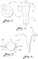
- the diffuser cooling holes 17 of an airfoil tip useful for understanding the present invention have a diffuser portion 24 therein that is configured to diffuse cooling air as it exits the diffuser cooling hole 17.
- Such diffuser portion 24 flares outwardly from the longitudinal axis AA of the diffuser cooling hole 17 as shown in FIG. 4 , and may comprise the entire perimeter or circumference of the diffuser portion 24 as illustrated in FIG. 3 .
- the diffuser cooling holes 17 further include a generally straight (cylindrical in the axial direction) round cross section portion 25 as illustrated in FIG. 4 that communicates with the hollow interior 20 of the turbine blade tip, and receives the cooling gas therefrom.
- the term "diffuser cooling hole” is intended to mean a cooling hole that tends to diffuse and/or reduce the flow rate of cooling gas at the point where the cooling gas exits the cooling hole, as distinguished from fully straight-walled or cylindrical cooling holes, which do not perform in this manner.
- the diffuser portion 24 flares generally outwardly relative to the longitudinal axis AA of the diffuser cooling hole 17, and may be generally conical in shape in the axial direction and round in cross section, although other configurations for the diffuser portion 24, including, without limitation, parabolic, hyperbolic, semicircular, semi-elliptical, and/or semi-oval, for example, in the axial direction, and elliptical, oval, square, rectangular, and/ or round, for example, in cross section, are also possible, provided the configuration tends to have an exit 26 with a greater area than a cross sectional area of the diffuser portion upstream of the exit, and tends to diffuse and/or reduce the flow rate of the cooling gas at the point 26 it exits the tip shelf, and tends to create a curtain of cooling gas along the tip shelf recess 22.
- the diffuser portion 24 of the diffuser cooling holes 17 may extend only a portion of the way around the cooling hole perimeter, e.g., in the case of a round diffuser in cross section, the diffuser portion 24 may extend 180° around the circumference, being half conical, for example, and half cylindrical, thereby creating a one-sided diffuser. As illustrated in FIG. 4 , the diffuser portion 24 may flare outwardly relative to the longitudinal axis AA of the diffuser cooling hole 17 by an angle ⁇ of about 0°-20°, and even more specifically about 5°, although other angles are of course possible.
- the diffuser cooling hole may behave virtually like a straight sided cylindrical hole, and if the angle ⁇ is much beyond the highest value of the range indicated, flow separation may occur, resulting in a loss of diffusion and a decrease in cooling effectiveness.
- one or more of the diffuser cooling holes 17 are slotted at the point of exit 26 along the tip shelf 15, with one or more slots 27 on the side of the diffuser cooling hole 17 positioned generally parallel to the longitudinal direction of the tip shelf recess 22, i.e., directing cooling air forward as illustrated by arrow A and/or aft as illustrated by arrow B along the tip shelf 15. Additional slots 27 may be positioned around the diffuser cooling hole(s) 17 to direct cooling air in other directions. When such slots 27 are used, the diffuser cooling holes 17 may be either straight or diffused in the axial direction.
- the slots 27 are straight with parallel sides 28 and arcuate bases 29, as alternative examples the slots 27 may have converging or diverging sides 28, curved sides 28, or other configurations, and may have a straight base 29 or other configurations as will now be appreciated by those of ordinary skill in the art.
- the diffuser cooling holes 17 illustrated in FIGS. 5 and 6 may be connected to at least one other similar cooling hole 17 by extending neighboring slots 27 of each diffuser cooling hole 17 until they join to form one slot connecting the two neighboring diffuser cooling holes 17.
- the size and/or shape of the diffuser cooling holes 17 arrayed along the tip shelf 15 it may be possible to vary the flow rate and coverage of cooling gas in different regions of the tip shelf 15 with the objective of equalizing the temperature profile across the turbine tip.
- the flow rate is controlled by the size of the straight round portion 25 of the diffuser cooling holes 17.
- the diffuser portion 24 controls the spread and exit velocity of the flow. For a given flowrate, (i.e. fixed straight round portion 25), the diffuser portion 24 can be adjusted to tune the local temperatures.
- the diffuser portion 24 By making the diffuser portion 24 larger, the flow is spread out over a larger area providing better film coverage in regions known to experience higher temperatures. If the diffuser portion 24 is made smaller to approach the size and shape of the straight round portion 25, then the cooling benefits of the diffuser design are lessened.
- FIG. 7 Illustrated in FIG. 7 is a perspective view of a cutting tool generally 30 that may be used to drill and/or punch diffuser cooling holes 17 having substantially the same shape as the tool 30 in the tip shelf 15 using methods known to those of ordinary skill in the art.
- the disclosure may help to enhance film coverage over the pressure side tip rim, thereby reducing temperature gradients which are detrimental to LCF life.
- the disclosure may also help to distribute cooling air more evenly to the pressure side tip rim, thereby reducing overall surface temperatures.
- the use of diffuser shaped holes according to the present disclosure can lead to lower cooling flow usage relative to round straight holes for the same temperature limits, or equal cooling flow usage relative to round straight holes with decreased temperatures.
Landscapes
- Engineering & Computer Science (AREA)
- Mechanical Engineering (AREA)
- General Engineering & Computer Science (AREA)
- Turbine Rotor Nozzle Sealing (AREA)
Description
- The present disclosure relates generally to gas turbine engines, and, more specifically, to a turbine blade assembly having improved tip cooling.
- A gas turbine engine includes one or more turbine blade rows disposed downstream of a combustor which extracts energy from combustion gases generated by the combustor. Disposed radially outwardly of the rotor blade tips may be a stator shroud which is spaced from the blade tips to provide a relatively small clearance between the blade tips and shroud for reducing leakage of the combustion gases over the blade tips during operation. Each of the rotor blades includes conventionally known pressure and suction sides which are preferentially aerodynamically contoured for extracting as much energy as possible from the combustion gases flowing over the rotor blades. The pressure and suction sides extend to the blade tip and are disposed as close as possible to the stator shroud for maximizing the amount of energy extracted from the combustion gases. The clearance, however, between the blade tips and the stator shroud must nevertheless be adequate to minimize the occurrence of blade tip rubs during operation, which may damage the blade tips.
- Un-shrouded blades use a squealer tip to reduce hot gas leakage over the blade tip and reduce performance penalties. Such a tip design typically requires ribs, generally a pressure side rib and a suction side rib, to protrude from the blade tip floor. These ribs are relatively thin, which makes them difficult to cool effectively through conduction. Turbine blade tips and associated ribs, moreover, are exposed to the very high temperatures of combustion gasses flowing over their outside surfaces. These high temperatures and low cooling effectiveness lead to durability issues on the tip ribs and the potential for blade fallout at the end of the blade's life interval. Any tip ribs that suffer oxidation or cracks beyond the squealer floor will render a blade irreparable regardless of the overall airfoil condition.
- Whether shrouded or un-shrouded, turbine rotor blades are typically hollow for channeling cooling air through the interior of the blade. This cooling air is provided from a conventional compressor of the gas turbine engine to cool the blades from the heat flux generated by the combustion gases flowing over the blades. The tip, or tip cap, portion of the blades is particularly susceptible to the damaging effects of the hot combustion gases and must be suitably cooled for reducing blade tip distress in the form of oxidation and thermal fatigue during operation. As the blade tip erodes during operation due to the blade tip distress, the pressure and/or suction sides of the blade are adversely affected, which decreases the aerodynamic efficiency of the blade used for extracting energy from the combustion gases. In addition, such erosion of the blade tip also increases the clearance between the blade tip and the stator shroud, which allows more of the combustion gases to leak over the blade tip, and, therefore, extraction of the energy therefrom is lost which also decreases aerodynamic efficiency.
- Numerous conventional blade tip cap designs exist for maintaining the proper pressure and suction side flow surfaces of the blade at the tip cap as well as providing minimum clearances with the stator shroud. Numerous cooling configurations also exist for cooling the blade tips or blade tip caps for meeting life requirements of the blades without undesirable erosion thereof. Conventional design practice makes use of a tip shelf recess or an L-shaped trough defined by the tip shelf and a first tip wall disposed on the pressure side of the blade. The tip shelf may offer the advantage of providing a discontinuity on the airfoil pressure side of the blade tip, causing combustion gasses to separate from the surface of the blade tip, which may decreases the heat transfer capability of the hot gasses to the blade tip, and therefore may decrease the heat flux into the blade tip. Conventional design practice also makes use of straight round holes through the tip shelf for passing cooling gas from the hollow blade interior to the tip shelf and pressure side rib, with resultant tip cooling due to convective and film effects. The tip shelf recess provides a region for the cooling air exiting the interior of the blade to accumulate, thereby providing a film blanket of cooling air between the hot combustion gasses and the blade tip, thereby further cooling the blade tip.
-
EP 1059419 discloses a turbine airfoil including cooling gas feed holes in the tip floor, and various tip arrangements. - Another approach to cooling the blade tip is to increase the total number of straight round cooling holes in the tip shelf to increase the total cooling flow and decrease the space available for hot gas to interact with the surface. Since cooling of the blade, including the blade tip, uses a portion of the compressed air from the gas turbine compressor, however, that air is unavailable for combustion in the combustor of the engine which decreases the overall efficiency of the gas turbine engine. Accordingly, cooling of the blade, including the blade tip, should be accomplished with as little compressed air as possible to minimize the loss in gas turbine engine efficiency.
- Still another approach involves creating channels or indentations in the pressure side rib to direct cooling flow from the pressure side tip holes over the rim at desired locations to better cover the surface.
- Yet another approach is to thicken the pressure side rim and drill cooling holes through the center and exit at the rim top face. It would be desirable to provide tip shelf cooling holes that are economical to install, provide an acceptable flow of cooling air over the blade tip shelf, and provide an improved film blanket of cooling air spread across the tip shelf, thereby better protecting the blade tip from hot combustion gasses.
- According to the present invention, there is provided a turbine blade assembly according to
claim 1. Diffuser cooling holes allow the cooling gas to begin diffusing before exiting the cooling hole and covering a larger area than a straight hole would provide. The diffused cooling gas flows over the pressure side rail covering a larger surface area than is typical using straight round cooling holes. This increased coverage provides more even cooling to the pressure side rail and less near-surface leakage paths for hot gas to occupy. The cooling gas diffusion also serves to reduce the coolant exit velocity into the tip shelf cavity. The reduced velocity increases the amount of cooling gas that is entrained in the shelf, thereby enhancing the overall cooling into the pressure side rail from the tip shelf region. - The following description is better understood when read in conjunction with the appended drawings.
-
FIG. 1 is a schematic, perspective, partly sectional view of the tip portion of a gas turbine engine blade example of the disclosure. -
FIG. 2 is a top plan view of the tip portion ofFIG. 1 . -
FIG. 3 is a top plan view of a diffuser cooling hole useful for understanding the present invention. -
FIG. 4 is a side cross sectional view of the diffuser cooling hole ofFIG. 3 . -
FIG. 5 is a top plan view of the diffuser portion of a cooling hole according to an embodiment of the present invention. -
FIG. 6 is a side cross sectional view of the cooling hole ofFIG. 5 . -
FIG. 7 is a perspective view of a tool body used for cutting a diffuser hole useful for understanding the present invention. -
FIG. 8 is a partial cross sectional view of a portion of the tip portion of a gas turbine engine blade example of the disclosure. - Gas turbine blades having a cooling channel therein for channeling cooling air to the tip of the blade are generally known. As is known, the turbine blades typically include an airfoil including a first side joined to a second side at spaced apart leading and trailing edges to define therein a flow channel for channeling cooling air through the airfoil to cool the airfoil from combustion gases flowing over the first and second sides. The airfoil typically has a tip at its distal end and a root having a dovetail extending from the root for mounting the blade to a rotor disk. The airfoil tip typically includes a tip floor extending between the airfoil first and second sides and between the leading and trailing edges for enclosing the airfoil for containing cooling air in the air flow channel. A first tip wall typically extends from the tip floor at the airfoil first side to form an extension thereof. A second tip wall typically extends from the tip floor at the airfoil second side to form an extension thereof, and is spaced in part from the first tip wall to define therebetween an outwardly facing tip plenum. The first tip wall is typically recessed at least in part from the airfoil first side to define an outwardly facing tip shelf extending between the leading and trailing edges to provide a discontinuity in the airfoil first side, the first tip wall and the tip shelf defining therebetween a tip shelf recess or trough. In an alternative form, the tip shelf may extend from the leading edge to a point short of the trailing edge, a configuration sometimes referred to as a "partial tip shelf."
- Referring to
FIGS. 1 ,2 , and8 , there is shown a portion of a turbine blade squealer tip, generally 10, of an embodiment of the present invention. Thesquealer tip 10 is located at the distal end of a turbine blade assembly. The turbine blade assembly may have at its proximal end an airfoil root for mounting the blade to a rotor disc of a gas turbine engine. The blade assembly andsquealer tip 10 have along their length between the airfoil root and the blade tip a leading edge 11 that transitions to a taperedtrailing edge 12. The blade assembly and squealer tip further have along its width between the leading edge 11 and trailing edge 12 afirst wall 13 on the pressure side of the assembly, and asecond wall 14 on the suction side of the assembly opposite thefirst wall 13. Thefirst wall 13 has a generally concave shape and has disposed thereon a tip shelf, sometimes referred to as a butt shelf or bucket tip shelf, 15, that runs substantially from the leading edge 11 to thetrailing edge 12. Thesecond wall 14 has a substantially convex shape. - As illustrated, the
tip shelf 15 is formed in asquealer tip rim 16 that is positioned at the blade tip. Thetip shelf 15 has positioned therealong one or more diffuser cooling holes 17. As further illustrated, the tip floor or plenum, generally 18, may include one or more tip floor cooling holes 19 distributed thereon. These diffuser cooling holes 17 and tip floor cooling holes 19 may be in flow communication with a substantiallyhollow interior 20 of the blade assembly, which may include a serpentine flow channel configuration formed by one or moreinternal ribs 21 for channeling cooling air, represented by the arrows "A" inFIG. 8 , through thehollow interior 20 of the blade in order to cool it. The cooling air may be provided by a compressor (not shown) of the gas turbine and is conventionally channeled through the rotor disk into the blade. Thetip shelf 15 may include an L-shaped tip trough ortip shelf recess 22 formed by thetip shelf 15 and the firstvertical tip wall 23, which may be, but is not always, generally vertical and perpendicular to thetip shelf 15. In other examples, thetip wall 23 may be angled, i.e., non-perpendicular, relative to thetip shelf 15. A secondvertical tip wall 31 is spaced apart from the firstvertical tip wall 23 on the suction side of the blade tip, with thetip floor 18 being formed therebetween. While the example illustrated inFIG. 1 includes a secondvertical tip wall 31 that may be generally perpendicular to thetip floor 18, this may not always be the case, and thesecond tip wall 31 may in some embodiments be angled, i.e., non-perpendicular, relative to thetip floor 18. - As more particularly shown in
FIGS. 3 and 4 , the diffuser cooling holes 17 of an airfoil tip useful for understanding the present invention have adiffuser portion 24 therein that is configured to diffuse cooling air as it exits thediffuser cooling hole 17.Such diffuser portion 24 flares outwardly from the longitudinal axis AA of thediffuser cooling hole 17 as shown inFIG. 4 , and may comprise the entire perimeter or circumference of thediffuser portion 24 as illustrated inFIG. 3 . The diffuser cooling holes 17 further include a generally straight (cylindrical in the axial direction) roundcross section portion 25 as illustrated inFIG. 4 that communicates with thehollow interior 20 of the turbine blade tip, and receives the cooling gas therefrom. - As used herein, the term "diffuser cooling hole" is intended to mean a cooling hole that tends to diffuse and/or reduce the flow rate of cooling gas at the point where the cooling gas exits the cooling hole, as distinguished from fully straight-walled or cylindrical cooling holes, which do not perform in this manner. In one embodiment of the invention, the
diffuser portion 24 flares generally outwardly relative to the longitudinal axis AA of thediffuser cooling hole 17, and may be generally conical in shape in the axial direction and round in cross section, although other configurations for thediffuser portion 24, including, without limitation, parabolic, hyperbolic, semicircular, semi-elliptical, and/or semi-oval, for example, in the axial direction, and elliptical, oval, square, rectangular, and/ or round, for example, in cross section, are also possible, provided the configuration tends to have anexit 26 with a greater area than a cross sectional area of the diffuser portion upstream of the exit, and tends to diffuse and/or reduce the flow rate of the cooling gas at thepoint 26 it exits the tip shelf, and tends to create a curtain of cooling gas along thetip shelf recess 22. It is also possible for thediffuser portion 24 of the diffuser cooling holes 17 to extend only a portion of the way around the cooling hole perimeter, e.g., in the case of a round diffuser in cross section, thediffuser portion 24 may extend 180° around the circumference, being half conical, for example, and half cylindrical, thereby creating a one-sided diffuser. As illustrated inFIG. 4 , thediffuser portion 24 may flare outwardly relative to the longitudinal axis AA of thediffuser cooling hole 17 by an angle θ of about 0°-20°, and even more specifically about 5°, although other angles are of course possible. If, however, the angle θ is too low, the diffuser cooling hole may behave virtually like a straight sided cylindrical hole, and if the angle θ is much beyond the highest value of the range indicated, flow separation may occur, resulting in a loss of diffusion and a decrease in cooling effectiveness. - According to the present invention, as illustrated in
FIGS. 5 and 6 , one or more of the diffuser cooling holes 17 are slotted at the point ofexit 26 along thetip shelf 15, with one ormore slots 27 on the side of thediffuser cooling hole 17 positioned generally parallel to the longitudinal direction of thetip shelf recess 22, i.e., directing cooling air forward as illustrated by arrow A and/or aft as illustrated by arrow B along thetip shelf 15.Additional slots 27 may be positioned around the diffuser cooling hole(s) 17 to direct cooling air in other directions. Whensuch slots 27 are used, the diffuser cooling holes 17 may be either straight or diffused in the axial direction. Although theslots 27 according to the present invention are straight withparallel sides 28 andarcuate bases 29, as alternative examples theslots 27 may have converging or divergingsides 28, curved sides 28, or other configurations, and may have astraight base 29 or other configurations as will now be appreciated by those of ordinary skill in the art. In another example, the diffuser cooling holes 17 illustrated inFIGS. 5 and 6 may be connected to at least one othersimilar cooling hole 17 by extending neighboringslots 27 of eachdiffuser cooling hole 17 until they join to form one slot connecting the two neighboring diffuser cooling holes 17. - As will now be appreciated, by varying the size and/or shape of the diffuser cooling holes 17 arrayed along the
tip shelf 15, it may be possible to vary the flow rate and coverage of cooling gas in different regions of thetip shelf 15 with the objective of equalizing the temperature profile across the turbine tip. The flow rate is controlled by the size of thestraight round portion 25 of the diffuser cooling holes 17. By increasing the size of thestraight round portion 25, higher flow rates can be delivered to regions known to experience higher temperatures and vice versa. Thediffuser portion 24 controls the spread and exit velocity of the flow. For a given flowrate, (i.e. fixed straight round portion 25), thediffuser portion 24 can be adjusted to tune the local temperatures. By making thediffuser portion 24 larger, the flow is spread out over a larger area providing better film coverage in regions known to experience higher temperatures. If thediffuser portion 24 is made smaller to approach the size and shape of thestraight round portion 25, then the cooling benefits of the diffuser design are lessened. - Illustrated in
FIG. 7 is a perspective view of a cutting tool generally 30 that may be used to drill and/or punch diffuser cooling holes 17 having substantially the same shape as thetool 30 in thetip shelf 15 using methods known to those of ordinary skill in the art. - The disclosure may help to enhance film coverage over the pressure side tip rim, thereby reducing temperature gradients which are detrimental to LCF life. The disclosure may also help to distribute cooling air more evenly to the pressure side tip rim, thereby reducing overall surface temperatures. The use of diffuser shaped holes according to the present disclosure can lead to lower cooling flow usage relative to round straight holes for the same temperature limits, or equal cooling flow usage relative to round straight holes with decreased temperatures.
- This written description uses examples to disclose the various embodiments, including the best mode, and also to enable any person of ordinary skill in the art to practice the disclosure, including making and using any devices or systems and performing any incorporated methods or apparatus. The patentable scope of the invention is defined by the claims, and may include other examples that occur to those of ordinary skill in the art. Such other examples are intended to be within the scope of the claims if they have structural elements that do not differ from the literal language of the claims, or if they include equivalent structural elements with insubstantial differences from the literal languages of the claims.
Claims (4)
- A turbine blade assembly comprising:
an airfoil including a first wall (13) on the pressure side joined to a second wall (14) on the suction side at spaced apart leading and trailing edges (11, 12) to define therein a substantially hollow interior (20) including a flow channel for channeling cooling gas through said airfoil to cool said airfoil from combustion gases flowing over said pressure side and said suction side, said airfoil having a tip, said first wall (13) having a generally concave shape and having disposed thereon a radially outwardly facing tip shelf (15), the tip shelf (15) being formed in a squealer tip rim (16) positioned at said tip, said tip comprising:a tip floor (18) extending between said pressure side and said suction side and between said leading and trailing edges for enclosing said airfoil for containing said cooling gas in said flow channel;a first squealer tip wall (23) extending from said tip floor at said airfoil pressure side to form an extension thereof;a second squealer tip wall (31) extending from said tip floor (18) at said airfoil suction side to form an extension thereof and spaced in part from said first squealer tip wall (23) to define therebetween a radially outwardly facing tip plenum;said first squealer tip wall (23) being recessed at least in part from said airfoil pressure side to define said outwardly facing tip shelf (15) extending between said leading and trailing edges to provide a discontinuity in said airfoil pressure side, said first squealer tip wall (13) and said outwardly facing tip shelf (15) defining therebetween a tip shelf recess (22); anda plurality of diffuser cooling holes (17) positioned along and extending through said tip shelf (15) in flow communication between said flow channel and said tip shelf recess (22) for channeling a portion of said cooling gas into said tip shelf recess (22), wherein one or more of the plurality of diffuser cooling holes (17) comprise:a diffuser portion (24) shaped to diffuse cooling gas exiting said diffuser cooling hole (17), said diffuser portion (24) comprising at least a portion thereof having a radially outwardly flaring section, the outwardly flaring section flaring outward at an angle relative to a longitudinal axis of said diffuser cooling hole (15),characterized in that said one or more of the plurality of diffuser cooling holes (17) further comprise:a generally straight portion (25) with a first end in flow communication with the substantially hollow interior portion (20) of said turbine blade assembly, and a second end in flow communication with said diffuser portion (24), anda first slot (27) and a second slot (27) extending from said outwardly flaring section at a point of exit (26) along the tip shelf (15) and positioned generally parallel to the longitudinal direction of the tip shelf recess (22) to direct cooling gas in a forward direction and in an aft direction, opposite to the forward direction, along said tip shelf (15), wherein the first and second slots (27) each have longitudinally extending sides (28) and a width from one side to the other which is significantly smaller than the smallest width of the diffuser portion (24) at the point of exit (26) where the cooling gas exits the tip shelf (15). - The turbine blade assembly of claim 1 wherein said outwardly flaring section is configured to have the flow exit (26) with a larger area than a cross sectional area of the diffuser portion (24) upstream of the flow exit (26).
- The turbine blade assembly of claim 1 wherein said outwardly flaring section comprises an entire circumference of said diffuser portion (24).
- The turbine blade assembly of claim 1 wherein one of said plurality of diffuser cooling holes (17) comprises a different size and/or shape relative to another of said plurality of diffuser cooling holes (17), thereby providing different flow rates of cooling gas in different regions of the tip shelf (15).
Applications Claiming Priority (1)
| Application Number | Priority Date | Filing Date | Title |
|---|---|---|---|
| US13/664,503 US9103217B2 (en) | 2012-10-31 | 2012-10-31 | Turbine blade tip with tip shelf diffuser holes |
Publications (2)
| Publication Number | Publication Date |
|---|---|
| EP2728117A1 EP2728117A1 (en) | 2014-05-07 |
| EP2728117B1 true EP2728117B1 (en) | 2021-03-10 |
Family
ID=49486365
Family Applications (1)
| Application Number | Title | Priority Date | Filing Date |
|---|---|---|---|
| EP13190436.9A Active EP2728117B1 (en) | 2012-10-31 | 2013-10-28 | Turbine blade tip with tip shelf diffuser holes |
Country Status (3)
| Country | Link |
|---|---|
| US (1) | US9103217B2 (en) |
| EP (1) | EP2728117B1 (en) |
| JP (1) | JP6254819B2 (en) |
Families Citing this family (17)
| Publication number | Priority date | Publication date | Assignee | Title |
|---|---|---|---|---|
| US9429027B2 (en) | 2012-04-05 | 2016-08-30 | United Technologies Corporation | Turbine airfoil tip shelf and squealer pocket cooling |
| US8968437B2 (en) * | 2012-05-02 | 2015-03-03 | Michael J Kline | Jet engine with deflector |
| US9103217B2 (en) * | 2012-10-31 | 2015-08-11 | General Electric Company | Turbine blade tip with tip shelf diffuser holes |
| US9995147B2 (en) | 2015-02-11 | 2018-06-12 | United Technologies Corporation | Blade tip cooling arrangement |
| US10208602B2 (en) * | 2015-04-27 | 2019-02-19 | United Technologies Corporation | Asymmetric diffuser opening for film cooling holes |
| KR101885413B1 (en) * | 2015-07-31 | 2018-08-03 | 두산중공업 주식회사 | A gas turbine combustor swirler |
| US10436038B2 (en) * | 2015-12-07 | 2019-10-08 | General Electric Company | Turbine engine with an airfoil having a tip shelf outlet |
| US10196904B2 (en) | 2016-01-24 | 2019-02-05 | Rolls-Royce North American Technologies Inc. | Turbine endwall and tip cooling for dual wall airfoils |
| CN109154200B (en) * | 2016-05-24 | 2021-06-15 | 通用电气公司 | Airfoil and blade for a turbine engine, and corresponding method of flowing a cooling fluid |
| US10436040B2 (en) | 2017-01-13 | 2019-10-08 | Rolls-Royce Corporation | Airfoil with dual-wall cooling for a gas turbine engine |
| US20180320530A1 (en) * | 2017-05-05 | 2018-11-08 | General Electric Company | Airfoil with tip rail cooling |
| US10711618B2 (en) * | 2017-05-25 | 2020-07-14 | Raytheon Technologies Corporation | Turbine component with tip film cooling and method of cooling |
| US10822959B2 (en) * | 2017-06-15 | 2020-11-03 | Raytheon Technologies Corporation | Blade tip cooling |
| CN110566283A (en) * | 2019-10-09 | 2019-12-13 | 西北工业大学 | Air film cooling structure for top of high-pressure turbine power blade |
| DE102021204782A1 (en) * | 2021-05-11 | 2022-11-17 | Siemens Energy Global GmbH & Co. KG | Improved blade tip in new or repaired part and process |
| US11898460B2 (en) | 2022-06-09 | 2024-02-13 | General Electric Company | Turbine engine with a blade |
| US11927111B2 (en) | 2022-06-09 | 2024-03-12 | General Electric Company | Turbine engine with a blade |
Family Cites Families (26)
| Publication number | Priority date | Publication date | Assignee | Title |
|---|---|---|---|---|
| US4142824A (en) | 1977-09-02 | 1979-03-06 | General Electric Company | Tip cooling for turbine blades |
| US4606701A (en) * | 1981-09-02 | 1986-08-19 | Westinghouse Electric Corp. | Tip structure for a cooled turbine rotor blade |
| US4893987A (en) * | 1987-12-08 | 1990-01-16 | General Electric Company | Diffusion-cooled blade tip cap |
| US5183385A (en) * | 1990-11-19 | 1993-02-02 | General Electric Company | Turbine blade squealer tip having air cooling holes contiguous with tip interior wall surface |
| US5261789A (en) | 1992-08-25 | 1993-11-16 | General Electric Company | Tip cooled blade |
| JP3137527B2 (en) | 1994-04-21 | 2001-02-26 | 三菱重工業株式会社 | Gas turbine blade tip cooling system |
| US6190129B1 (en) * | 1998-12-21 | 2001-02-20 | General Electric Company | Tapered tip-rib turbine blade |
| US6224336B1 (en) * | 1999-06-09 | 2001-05-01 | General Electric Company | Triple tip-rib airfoil |
| US6422821B1 (en) * | 2001-01-09 | 2002-07-23 | General Electric Company | Method and apparatus for reducing turbine blade tip temperatures |
| US6602052B2 (en) | 2001-06-20 | 2003-08-05 | Alstom (Switzerland) Ltd | Airfoil tip squealer cooling construction |
| US6554575B2 (en) * | 2001-09-27 | 2003-04-29 | General Electric Company | Ramped tip shelf blade |
| US6994514B2 (en) | 2002-11-20 | 2006-02-07 | Mitsubishi Heavy Industries, Ltd. | Turbine blade and gas turbine |
| US6932571B2 (en) * | 2003-02-05 | 2005-08-23 | United Technologies Corporation | Microcircuit cooling for a turbine blade tip |
| US6971851B2 (en) | 2003-03-12 | 2005-12-06 | Florida Turbine Technologies, Inc. | Multi-metered film cooled blade tip |
| US6991430B2 (en) | 2003-04-07 | 2006-01-31 | General Electric Company | Turbine blade with recessed squealer tip and shelf |
| US7118337B2 (en) * | 2004-06-17 | 2006-10-10 | Siemens Power Generation, Inc. | Gas turbine airfoil trailing edge corner |
| US7097419B2 (en) * | 2004-07-26 | 2006-08-29 | General Electric Company | Common tip chamber blade |
| US7510376B2 (en) | 2005-08-25 | 2009-03-31 | General Electric Company | Skewed tip hole turbine blade |
| US7473073B1 (en) | 2006-06-14 | 2009-01-06 | Florida Turbine Technologies, Inc. | Turbine blade with cooled tip rail |
| US7857587B2 (en) * | 2006-11-30 | 2010-12-28 | General Electric Company | Turbine blades and turbine blade cooling systems and methods |
| US7704045B1 (en) | 2007-05-02 | 2010-04-27 | Florida Turbine Technologies, Inc. | Turbine blade with blade tip cooling notches |
| US8628299B2 (en) * | 2010-01-21 | 2014-01-14 | General Electric Company | System for cooling turbine blades |
| GB201006451D0 (en) * | 2010-04-19 | 2010-06-02 | Rolls Royce Plc | Blades |
| US9085988B2 (en) | 2010-12-24 | 2015-07-21 | Rolls-Royce North American Technologies, Inc. | Gas turbine engine flow path member |
| US9091177B2 (en) * | 2012-03-14 | 2015-07-28 | United Technologies Corporation | Shark-bite tip shelf cooling configuration |
| US9103217B2 (en) * | 2012-10-31 | 2015-08-11 | General Electric Company | Turbine blade tip with tip shelf diffuser holes |
-
2012
- 2012-10-31 US US13/664,503 patent/US9103217B2/en active Active
-
2013
- 2013-10-24 JP JP2013220697A patent/JP6254819B2/en active Active
- 2013-10-28 EP EP13190436.9A patent/EP2728117B1/en active Active
Non-Patent Citations (1)
| Title |
|---|
| None * |
Also Published As
| Publication number | Publication date |
|---|---|
| JP6254819B2 (en) | 2017-12-27 |
| US20140271226A1 (en) | 2014-09-18 |
| JP2014092153A (en) | 2014-05-19 |
| EP2728117A1 (en) | 2014-05-07 |
| US9103217B2 (en) | 2015-08-11 |
Similar Documents
| Publication | Publication Date | Title |
|---|---|---|
| EP2728117B1 (en) | Turbine blade tip with tip shelf diffuser holes | |
| US7857587B2 (en) | Turbine blades and turbine blade cooling systems and methods | |
| JP5503140B2 (en) | Divergent turbine nozzle | |
| US8205458B2 (en) | Duplex turbine nozzle | |
| JP4713423B2 (en) | Oblique tip hole turbine blade | |
| US9175569B2 (en) | Turbine airfoil trailing edge cooling slots | |
| US9145773B2 (en) | Asymmetrically shaped trailing edge cooling holes | |
| US20140023497A1 (en) | Cooled turbine blade tip shroud with film/purge holes | |
| US9017026B2 (en) | Turbine airfoil trailing edge cooling slots | |
| US20130302176A1 (en) | Turbine airfoil trailing edge cooling slot | |
| JP3213107U (en) | Collision system for airfoils | |
| US10450874B2 (en) | Airfoil for a gas turbine engine | |
| EP3669054B1 (en) | Turbine blade and corresponding method of servicing |
Legal Events
| Date | Code | Title | Description |
|---|---|---|---|
| PUAI | Public reference made under article 153(3) epc to a published international application that has entered the european phase |
Free format text: ORIGINAL CODE: 0009012 |
|
| 17P | Request for examination filed |
Effective date: 20131028 |
|
| AK | Designated contracting states |
Kind code of ref document: A1 Designated state(s): AL AT BE BG CH CY CZ DE DK EE ES FI FR GB GR HR HU IE IS IT LI LT LU LV MC MK MT NL NO PL PT RO RS SE SI SK SM TR |
|
| AX | Request for extension of the european patent |
Extension state: BA ME |
|
| 17P | Request for examination filed |
Effective date: 20141107 |
|
| RBV | Designated contracting states (corrected) |
Designated state(s): AL AT BE BG CH CY CZ DE DK EE ES FI FR GB GR HR HU IE IS IT LI LT LU LV MC MK MT NL NO PL PT RO RS SE SI SK SM TR |
|
| STAA | Information on the status of an ep patent application or granted ep patent |
Free format text: STATUS: EXAMINATION IS IN PROGRESS |
|
| 17Q | First examination report despatched |
Effective date: 20190220 |
|
| GRAP | Despatch of communication of intention to grant a patent |
Free format text: ORIGINAL CODE: EPIDOSNIGR1 |
|
| STAA | Information on the status of an ep patent application or granted ep patent |
Free format text: STATUS: GRANT OF PATENT IS INTENDED |
|
| INTG | Intention to grant announced |
Effective date: 20201015 |
|
| GRAS | Grant fee paid |
Free format text: ORIGINAL CODE: EPIDOSNIGR3 |
|
| GRAA | (expected) grant |
Free format text: ORIGINAL CODE: 0009210 |
|
| STAA | Information on the status of an ep patent application or granted ep patent |
Free format text: STATUS: THE PATENT HAS BEEN GRANTED |
|
| AK | Designated contracting states |
Kind code of ref document: B1 Designated state(s): AL AT BE BG CH CY CZ DE DK EE ES FI FR GB GR HR HU IE IS IT LI LT LU LV MC MK MT NL NO PL PT RO RS SE SI SK SM TR |
|
| REG | Reference to a national code |
Ref country code: GB Ref legal event code: FG4D |
|
| REG | Reference to a national code |
Ref country code: AT Ref legal event code: REF Ref document number: 1370004 Country of ref document: AT Kind code of ref document: T Effective date: 20210315 Ref country code: CH Ref legal event code: EP |
|
| REG | Reference to a national code |
Ref country code: DE Ref legal event code: R096 Ref document number: 602013076149 Country of ref document: DE |
|
| REG | Reference to a national code |
Ref country code: IE Ref legal event code: FG4D |
|
| REG | Reference to a national code |
Ref country code: LT Ref legal event code: MG9D |
|
| PG25 | Lapsed in a contracting state [announced via postgrant information from national office to epo] |
Ref country code: HR Free format text: LAPSE BECAUSE OF FAILURE TO SUBMIT A TRANSLATION OF THE DESCRIPTION OR TO PAY THE FEE WITHIN THE PRESCRIBED TIME-LIMIT Effective date: 20210310 Ref country code: FI Free format text: LAPSE BECAUSE OF FAILURE TO SUBMIT A TRANSLATION OF THE DESCRIPTION OR TO PAY THE FEE WITHIN THE PRESCRIBED TIME-LIMIT Effective date: 20210310 Ref country code: GR Free format text: LAPSE BECAUSE OF FAILURE TO SUBMIT A TRANSLATION OF THE DESCRIPTION OR TO PAY THE FEE WITHIN THE PRESCRIBED TIME-LIMIT Effective date: 20210611 Ref country code: LT Free format text: LAPSE BECAUSE OF FAILURE TO SUBMIT A TRANSLATION OF THE DESCRIPTION OR TO PAY THE FEE WITHIN THE PRESCRIBED TIME-LIMIT Effective date: 20210310 Ref country code: NO Free format text: LAPSE BECAUSE OF FAILURE TO SUBMIT A TRANSLATION OF THE DESCRIPTION OR TO PAY THE FEE WITHIN THE PRESCRIBED TIME-LIMIT Effective date: 20210610 Ref country code: BG Free format text: LAPSE BECAUSE OF FAILURE TO SUBMIT A TRANSLATION OF THE DESCRIPTION OR TO PAY THE FEE WITHIN THE PRESCRIBED TIME-LIMIT Effective date: 20210610 |
|
| REG | Reference to a national code |
Ref country code: AT Ref legal event code: MK05 Ref document number: 1370004 Country of ref document: AT Kind code of ref document: T Effective date: 20210310 |
|
| REG | Reference to a national code |
Ref country code: NL Ref legal event code: MP Effective date: 20210310 |
|
| PG25 | Lapsed in a contracting state [announced via postgrant information from national office to epo] |
Ref country code: LV Free format text: LAPSE BECAUSE OF FAILURE TO SUBMIT A TRANSLATION OF THE DESCRIPTION OR TO PAY THE FEE WITHIN THE PRESCRIBED TIME-LIMIT Effective date: 20210310 Ref country code: RS Free format text: LAPSE BECAUSE OF FAILURE TO SUBMIT A TRANSLATION OF THE DESCRIPTION OR TO PAY THE FEE WITHIN THE PRESCRIBED TIME-LIMIT Effective date: 20210310 Ref country code: SE Free format text: LAPSE BECAUSE OF FAILURE TO SUBMIT A TRANSLATION OF THE DESCRIPTION OR TO PAY THE FEE WITHIN THE PRESCRIBED TIME-LIMIT Effective date: 20210310 |
|
| PG25 | Lapsed in a contracting state [announced via postgrant information from national office to epo] |
Ref country code: NL Free format text: LAPSE BECAUSE OF FAILURE TO SUBMIT A TRANSLATION OF THE DESCRIPTION OR TO PAY THE FEE WITHIN THE PRESCRIBED TIME-LIMIT Effective date: 20210310 |
|
| PG25 | Lapsed in a contracting state [announced via postgrant information from national office to epo] |
Ref country code: SM Free format text: LAPSE BECAUSE OF FAILURE TO SUBMIT A TRANSLATION OF THE DESCRIPTION OR TO PAY THE FEE WITHIN THE PRESCRIBED TIME-LIMIT Effective date: 20210310 Ref country code: AT Free format text: LAPSE BECAUSE OF FAILURE TO SUBMIT A TRANSLATION OF THE DESCRIPTION OR TO PAY THE FEE WITHIN THE PRESCRIBED TIME-LIMIT Effective date: 20210310 Ref country code: EE Free format text: LAPSE BECAUSE OF FAILURE TO SUBMIT A TRANSLATION OF THE DESCRIPTION OR TO PAY THE FEE WITHIN THE PRESCRIBED TIME-LIMIT Effective date: 20210310 Ref country code: CZ Free format text: LAPSE BECAUSE OF FAILURE TO SUBMIT A TRANSLATION OF THE DESCRIPTION OR TO PAY THE FEE WITHIN THE PRESCRIBED TIME-LIMIT Effective date: 20210310 |
|
| PG25 | Lapsed in a contracting state [announced via postgrant information from national office to epo] |
Ref country code: SK Free format text: LAPSE BECAUSE OF FAILURE TO SUBMIT A TRANSLATION OF THE DESCRIPTION OR TO PAY THE FEE WITHIN THE PRESCRIBED TIME-LIMIT Effective date: 20210310 Ref country code: ES Free format text: LAPSE BECAUSE OF FAILURE TO SUBMIT A TRANSLATION OF THE DESCRIPTION OR TO PAY THE FEE WITHIN THE PRESCRIBED TIME-LIMIT Effective date: 20210310 Ref country code: PL Free format text: LAPSE BECAUSE OF FAILURE TO SUBMIT A TRANSLATION OF THE DESCRIPTION OR TO PAY THE FEE WITHIN THE PRESCRIBED TIME-LIMIT Effective date: 20210310 Ref country code: PT Free format text: LAPSE BECAUSE OF FAILURE TO SUBMIT A TRANSLATION OF THE DESCRIPTION OR TO PAY THE FEE WITHIN THE PRESCRIBED TIME-LIMIT Effective date: 20210712 Ref country code: IS Free format text: LAPSE BECAUSE OF FAILURE TO SUBMIT A TRANSLATION OF THE DESCRIPTION OR TO PAY THE FEE WITHIN THE PRESCRIBED TIME-LIMIT Effective date: 20210710 Ref country code: RO Free format text: LAPSE BECAUSE OF FAILURE TO SUBMIT A TRANSLATION OF THE DESCRIPTION OR TO PAY THE FEE WITHIN THE PRESCRIBED TIME-LIMIT Effective date: 20210310 |
|
| REG | Reference to a national code |
Ref country code: DE Ref legal event code: R097 Ref document number: 602013076149 Country of ref document: DE |
|
| PLBE | No opposition filed within time limit |
Free format text: ORIGINAL CODE: 0009261 |
|
| STAA | Information on the status of an ep patent application or granted ep patent |
Free format text: STATUS: NO OPPOSITION FILED WITHIN TIME LIMIT |
|
| PG25 | Lapsed in a contracting state [announced via postgrant information from national office to epo] |
Ref country code: AL Free format text: LAPSE BECAUSE OF FAILURE TO SUBMIT A TRANSLATION OF THE DESCRIPTION OR TO PAY THE FEE WITHIN THE PRESCRIBED TIME-LIMIT Effective date: 20210310 Ref country code: DK Free format text: LAPSE BECAUSE OF FAILURE TO SUBMIT A TRANSLATION OF THE DESCRIPTION OR TO PAY THE FEE WITHIN THE PRESCRIBED TIME-LIMIT Effective date: 20210310 |
|
| 26N | No opposition filed |
Effective date: 20211213 |
|
| PG25 | Lapsed in a contracting state [announced via postgrant information from national office to epo] |
Ref country code: SI Free format text: LAPSE BECAUSE OF FAILURE TO SUBMIT A TRANSLATION OF THE DESCRIPTION OR TO PAY THE FEE WITHIN THE PRESCRIBED TIME-LIMIT Effective date: 20210310 |
|
| PG25 | Lapsed in a contracting state [announced via postgrant information from national office to epo] |
Ref country code: IT Free format text: LAPSE BECAUSE OF FAILURE TO SUBMIT A TRANSLATION OF THE DESCRIPTION OR TO PAY THE FEE WITHIN THE PRESCRIBED TIME-LIMIT Effective date: 20210310 |
|
| PG25 | Lapsed in a contracting state [announced via postgrant information from national office to epo] |
Ref country code: IS Free format text: LAPSE BECAUSE OF FAILURE TO SUBMIT A TRANSLATION OF THE DESCRIPTION OR TO PAY THE FEE WITHIN THE PRESCRIBED TIME-LIMIT Effective date: 20210710 |
|
| REG | Reference to a national code |
Ref country code: CH Ref legal event code: PL |
|
| REG | Reference to a national code |
Ref country code: BE Ref legal event code: MM Effective date: 20211031 |
|
| GBPC | Gb: european patent ceased through non-payment of renewal fee |
Effective date: 20211028 |
|
| PG25 | Lapsed in a contracting state [announced via postgrant information from national office to epo] |
Ref country code: MC Free format text: LAPSE BECAUSE OF FAILURE TO SUBMIT A TRANSLATION OF THE DESCRIPTION OR TO PAY THE FEE WITHIN THE PRESCRIBED TIME-LIMIT Effective date: 20210310 |
|
| PG25 | Lapsed in a contracting state [announced via postgrant information from national office to epo] |
Ref country code: LU Free format text: LAPSE BECAUSE OF NON-PAYMENT OF DUE FEES Effective date: 20211028 Ref country code: GB Free format text: LAPSE BECAUSE OF NON-PAYMENT OF DUE FEES Effective date: 20211028 Ref country code: BE Free format text: LAPSE BECAUSE OF NON-PAYMENT OF DUE FEES Effective date: 20211031 |
|
| PG25 | Lapsed in a contracting state [announced via postgrant information from national office to epo] |
Ref country code: LI Free format text: LAPSE BECAUSE OF NON-PAYMENT OF DUE FEES Effective date: 20211031 Ref country code: CH Free format text: LAPSE BECAUSE OF NON-PAYMENT OF DUE FEES Effective date: 20211031 |
|
| PG25 | Lapsed in a contracting state [announced via postgrant information from national office to epo] |
Ref country code: FR Free format text: LAPSE BECAUSE OF NON-PAYMENT OF DUE FEES Effective date: 20211031 |
|
| PG25 | Lapsed in a contracting state [announced via postgrant information from national office to epo] |
Ref country code: IE Free format text: LAPSE BECAUSE OF NON-PAYMENT OF DUE FEES Effective date: 20211028 |
|
| PG25 | Lapsed in a contracting state [announced via postgrant information from national office to epo] |
Ref country code: HU Free format text: LAPSE BECAUSE OF FAILURE TO SUBMIT A TRANSLATION OF THE DESCRIPTION OR TO PAY THE FEE WITHIN THE PRESCRIBED TIME-LIMIT; INVALID AB INITIO Effective date: 20131028 |
|
| PG25 | Lapsed in a contracting state [announced via postgrant information from national office to epo] |
Ref country code: CY Free format text: LAPSE BECAUSE OF FAILURE TO SUBMIT A TRANSLATION OF THE DESCRIPTION OR TO PAY THE FEE WITHIN THE PRESCRIBED TIME-LIMIT Effective date: 20210310 |
|
| REG | Reference to a national code |
Ref country code: DE Ref legal event code: R081 Ref document number: 602013076149 Country of ref document: DE Owner name: GENERAL ELECTRIC TECHNOLOGY GMBH, CH Free format text: FORMER OWNER: GENERAL ELECTRIC COMPANY, SCHENECTADY, NY, US |
|
| PGFP | Annual fee paid to national office [announced via postgrant information from national office to epo] |
Ref country code: DE Payment date: 20230920 Year of fee payment: 11 |
|
| PG25 | Lapsed in a contracting state [announced via postgrant information from national office to epo] |
Ref country code: MK Free format text: LAPSE BECAUSE OF FAILURE TO SUBMIT A TRANSLATION OF THE DESCRIPTION OR TO PAY THE FEE WITHIN THE PRESCRIBED TIME-LIMIT Effective date: 20210310 |
|
| PG25 | Lapsed in a contracting state [announced via postgrant information from national office to epo] |
Ref country code: TR Free format text: LAPSE BECAUSE OF FAILURE TO SUBMIT A TRANSLATION OF THE DESCRIPTION OR TO PAY THE FEE WITHIN THE PRESCRIBED TIME-LIMIT Effective date: 20210310 |