EP3336020A1 - Behälterfördervorrichtung - Google Patents
Behälterfördervorrichtung Download PDFInfo
- Publication number
- EP3336020A1 EP3336020A1 EP17207109.4A EP17207109A EP3336020A1 EP 3336020 A1 EP3336020 A1 EP 3336020A1 EP 17207109 A EP17207109 A EP 17207109A EP 3336020 A1 EP3336020 A1 EP 3336020A1
- Authority
- EP
- European Patent Office
- Prior art keywords
- retainer
- retainers
- movement
- along
- rail
- Prior art date
- Legal status (The legal status is an assumption and is not a legal conclusion. Google has not performed a legal analysis and makes no representation as to the accuracy of the status listed.)
- Withdrawn
Links
Images


Classifications
-
- B—PERFORMING OPERATIONS; TRANSPORTING
- B65—CONVEYING; PACKING; STORING; HANDLING THIN OR FILAMENTARY MATERIAL
- B65B—MACHINES, APPARATUS OR DEVICES FOR, OR METHODS OF, PACKAGING ARTICLES OR MATERIALS; UNPACKING
- B65B43/00—Forming, feeding, opening or setting-up containers or receptacles in association with packaging
- B65B43/42—Feeding or positioning bags, boxes, or cartons in the distended, opened, or set-up state; Feeding preformed rigid containers, e.g. tins, capsules, glass tubes, glasses, to the packaging position; Locating containers or receptacles at the filling position; Supporting containers or receptacles during the filling operation
- B65B43/52—Feeding or positioning bags, boxes, or cartons in the distended, opened, or set-up state; Feeding preformed rigid containers, e.g. tins, capsules, glass tubes, glasses, to the packaging position; Locating containers or receptacles at the filling position; Supporting containers or receptacles during the filling operation using roller-ways or endless conveyors
-
- B—PERFORMING OPERATIONS; TRANSPORTING
- B65—CONVEYING; PACKING; STORING; HANDLING THIN OR FILAMENTARY MATERIAL
- B65G—TRANSPORT OR STORAGE DEVICES, e.g. CONVEYORS FOR LOADING OR TIPPING, SHOP CONVEYOR SYSTEMS OR PNEUMATIC TUBE CONVEYORS
- B65G25/00—Conveyors comprising a cyclically-moving, e.g. reciprocating, carrier or impeller which is disengaged from the load during the return part of its movement
- B65G25/02—Conveyors comprising a cyclically-moving, e.g. reciprocating, carrier or impeller which is disengaged from the load during the return part of its movement the carrier or impeller having different forward and return paths of movement, e.g. walking beam conveyors
-
- B—PERFORMING OPERATIONS; TRANSPORTING
- B65—CONVEYING; PACKING; STORING; HANDLING THIN OR FILAMENTARY MATERIAL
- B65B—MACHINES, APPARATUS OR DEVICES FOR, OR METHODS OF, PACKAGING ARTICLES OR MATERIALS; UNPACKING
- B65B43/00—Forming, feeding, opening or setting-up containers or receptacles in association with packaging
- B65B43/42—Feeding or positioning bags, boxes, or cartons in the distended, opened, or set-up state; Feeding preformed rigid containers, e.g. tins, capsules, glass tubes, glasses, to the packaging position; Locating containers or receptacles at the filling position; Supporting containers or receptacles during the filling operation
- B65B43/46—Feeding or positioning bags, boxes, or cartons in the distended, opened, or set-up state; Feeding preformed rigid containers, e.g. tins, capsules, glass tubes, glasses, to the packaging position; Locating containers or receptacles at the filling position; Supporting containers or receptacles during the filling operation using grippers
- B65B43/465—Feeding or positioning bags, boxes, or cartons in the distended, opened, or set-up state; Feeding preformed rigid containers, e.g. tins, capsules, glass tubes, glasses, to the packaging position; Locating containers or receptacles at the filling position; Supporting containers or receptacles during the filling operation using grippers for bags
-
- B—PERFORMING OPERATIONS; TRANSPORTING
- B65—CONVEYING; PACKING; STORING; HANDLING THIN OR FILAMENTARY MATERIAL
- B65G—TRANSPORT OR STORAGE DEVICES, e.g. CONVEYORS FOR LOADING OR TIPPING, SHOP CONVEYOR SYSTEMS OR PNEUMATIC TUBE CONVEYORS
- B65G35/00—Mechanical conveyors not otherwise provided for
- B65G35/06—Mechanical conveyors not otherwise provided for comprising a load-carrier moving along a path, e.g. a closed path, and adapted to be engaged by any one of a series of traction elements spaced along the path
-
- B—PERFORMING OPERATIONS; TRANSPORTING
- B65—CONVEYING; PACKING; STORING; HANDLING THIN OR FILAMENTARY MATERIAL
- B65G—TRANSPORT OR STORAGE DEVICES, e.g. CONVEYORS FOR LOADING OR TIPPING, SHOP CONVEYOR SYSTEMS OR PNEUMATIC TUBE CONVEYORS
- B65G47/00—Article or material-handling devices associated with conveyors; Methods employing such devices
- B65G47/74—Feeding, transfer, or discharging devices of particular kinds or types
- B65G47/84—Star-shaped wheels or devices having endless travelling belts or chains, the wheels or devices being equipped with article-engaging elements
- B65G47/841—Devices having endless travelling belts or chains equipped with article-engaging elements
- B65G47/842—Devices having endless travelling belts or chains equipped with article-engaging elements the article-engaging elements being grippers
-
- B—PERFORMING OPERATIONS; TRANSPORTING
- B65—CONVEYING; PACKING; STORING; HANDLING THIN OR FILAMENTARY MATERIAL
- B65G—TRANSPORT OR STORAGE DEVICES, e.g. CONVEYORS FOR LOADING OR TIPPING, SHOP CONVEYOR SYSTEMS OR PNEUMATIC TUBE CONVEYORS
- B65G47/00—Article or material-handling devices associated with conveyors; Methods employing such devices
- B65G47/74—Feeding, transfer, or discharging devices of particular kinds or types
- B65G47/90—Devices for picking-up and depositing articles or materials
-
- B—PERFORMING OPERATIONS; TRANSPORTING
- B65—CONVEYING; PACKING; STORING; HANDLING THIN OR FILAMENTARY MATERIAL
- B65G—TRANSPORT OR STORAGE DEVICES, e.g. CONVEYORS FOR LOADING OR TIPPING, SHOP CONVEYOR SYSTEMS OR PNEUMATIC TUBE CONVEYORS
- B65G2201/00—Indexing codes relating to handling devices, e.g. conveyors, characterised by the type of product or load being conveyed or handled
- B65G2201/02—Articles
- B65G2201/0235—Containers
Definitions
- the present invention relates to a container conveying apparatus that is applied to a packaging system (packaging machine) in which a plurality of retainers are intermittently moved in one direction along an endless horizontal movement path, containers are supplied to the retainers on the movement path as the retainers are moved, and then predetermined packaging processing is sequentially carried out on the containers held by the retainers.
- a packaging system packaging machine
- predetermined packaging processing is sequentially carried out on the containers held by the retainers.
- Patent Document 1 discloses a packaging machine in which a plurality of retainers (each comprising a pair of grippers for gripping (holding) the side edges of a bag) are installed around a table that rotates intermittently.
- each retainer is moved intermittently along a circular movement path; and a bag is supplied to each retainer at a first stop position, after which, at various stop positions, the bag held by the retainer is subjected to various packaging processing steps including printing on the bag surface, opening up the mouth of the bag, filling the bag with solid items, filling the bag with a liquid material, performing a first seal to the bag mouth, performing a second seal to the bag mouth, and then cooling the sealed portions.
- the bag (the finished product bag) is thereafter released from the retainer and discharged outside of the packaging machine.
- Patent Document 2 discloses a double packaging machine in which a plurality of retainers (each comprising a pair of grippers for gripping (holding) the side edges of a bag) are installed around a table that rotates intermittently; and in this double packaging machine, two retainers are paired and moved intermittently along a predetermined movement path, with the one-time movement distance of each retainer set to be equal to the spacing between the pairs.
- the one-time stop duration for each retainer is set so as to match the step that takes the longest time. Accordingly, at a stop position at which a packaging step that takes only a short time (such as a sealing step) is performed, part of the stop duration is wasted. If the time required for a particular packaging processing step is no more than half the one-time stop duration, then only one corresponding packaging processing device should be sufficient. However, in order to perform this particular packaging processing step on two bags held by two retainers, which are paired, by a single packaging processing device, the two retainers must be sequentially stopped in front of the packaging processing device.
- Patent Document 3 discloses a packaging system in which a plurality of retainers (which are carriers that hold a tube container in an upright state) are moved along an endless movement path by a plurality of belt conveyers and pushers, and various packaging processing, such as a supply of tube containers (filled with contents and sealed) to the retainers, various inspections (more than one type of inspection) of the tube containers, and placement into a storage box, is carried out sequentially at a plurality of stop positions set along the movement path.
- a packaging processing device that performs the above-described packaging processing is installed near each stop position.
- a plurality of retainers are stopped at each stop position, and a plurality of tube containers are simultaneously supplied to the retainers, and a plurality of tube containers are simultaneously subjected to packaging processing such as a leak inspection.
- the number of retainers stopped at each stop position is a number that corresponds to the packaging processing device installed there (the number that can be processed by the packaging processing device at one time), and the stop duration of the retainers at each stop position is set so as to match the time the packaging processing to be carried there requires.
- the number of retainers stopped at each stop position and the stop duration can be set to the optimal value for each stop position depending on how long it takes to carry out the packaging processing at each stop position. More specifically, the less time the packaging processing takes, the fewer the number of retainers that are stopped at the stop position where that packaging processing is performed, and also the shorter the retainer stop duration is set for that stop position.
- the numerous retainers that are moved along the movement path are moved in different movement modes (the number of retainers stopped at a stop position, and the stop duration) depending on the different sections of the path. Accordingly, less stop duration is wasted at a stop position, and the number of packaging processing devices (or packaging processing members) to be installed can be reduced at stop positions where the packaging processing takes shorter time.
- the retainers are moved by a plurality of belt conveyors and pushers, and there are many places where the movement path changes the direction at right angles. Also, the retainers hit the stoppers and come to a stop a number of times even away from the stop positions where the packaging processing is performed. Therefore, the movement of the retainers is not smooth, and it is difficult to raise the moving speed of the retainers to improve the carrying capacity of the container conveying apparatus and in turn to boost the processing capacity of the packaging system. Also, when the moving speed of the retainer is raised, there is a greater impact when the retainers hit the stoppers, and this could result in damages to the retainers and cause impact noises, thus requiring parts to be replaced and imposing a greater burden on the operator. For this reason as well, it is difficult to raise the moving speed of the retainers and boost the processing capacity of the packaging system.
- the container conveying apparatus comprises:
- the container conveying apparatus of the present invention described above includes, for example, the following preferred embodiments.
- a retainer is a device that holds a container, and it is moved along the movement path to convey the container held thereby (see Patent Documents 1 to 3); and containers include, among others, bags, tubes, and cups.
- a plurality of retainers are moved along a movement path in different movement modes depending upon the sections of the movement path, and consequently there is less wasted stop time at stop positions, the number of packaging processing devices installed can be reduced in stop positions where the packaging processing takes a shorter time, or the number of packaging processing members installed can be reduced to make the packaging processing device more compact.
- the retainer is moved along the retainer movement rail, and the movement path of the retainers (in the top view shape of the retainer movement rail) is composed of a plurality of straight sections and the same number of arc sections, so that the retainers can be moved more smoothly and the moving speed of the retainers is increased to improve the conveyance capacity of the container conveying apparatus and the processing capacity of the packaging machine. Also, since the retainers are moved and stopped on the movement path by the first and second retainer holding members that are capable of holding the retainers, the impact caused by the movement and stoppage of the retainers is small, and damages to the retainers and impact noises are prevented.
- FIGS. 1 to 15 One embodiment of the container conveying apparatus according to the present invention, which constitutes part of a packaging machine, will now be described in detail below with reference to FIGS. 1 to 15 .
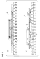
- the packaging machine shown in FIG. 1 includes a container conveying apparatus 2 for intermittently moving a plurality of retainers 1 in one direction (clockwise) along a horizontal movement path in a racetrack shape having two straight sections and two arc sections, and the packaging machine further includes a plurality of packaging processing devices disposed along the straight sections (A lane and B lane) of the movement path. Packaging processing devices are not disposed on the arc sections (A/B lane and B/A lane) of the movement path.
- the one-time movement distance of the retainer 1 is set to a distance that is two times the pitch p, and in the B lane, it is set to a distance that is four times the pitch p.
- the cycle of moving and stopping of the retainer 1 is repeated twice in the A lane while being performed once in the B lane. Therefore, the one-time stop duration of the retainers in the A lane is set shorter than the one-time stop duration of the retainers in the B lane.
- the packaging processing devices disposed on the A lane side are empty bag supply devices 3, a printing device 4, print inspection devices 5, an opening device 6, a sealing device 7, a cooling device 8, and a discharge conveyor 9, all of which are respectively disposed near stop positions (positions at which two retainers 1 are stopped) on the A lane. These packaging processing devices respectively perform various packaging processing simultaneously on two bags 10 held by the two retainers 1 stopped at each stop position. These packaging processing steps are those that can be carried out in a relatively short time.
- the number of these packaging processing devices can be reduced, or the devices can be made more compact (in the case of the printing device 4, for example, just two heads can be sufficient), compared to a case that the various packaging processing steps are simultaneously performed on four bags 10 held by four retainers 1.
- the packaging processing device disposed on the B lane side is a content supply device 11. Contents 12 are supplied by the content supply device 11 to bags 10 (total of four) which are held by four retainers stopped at a predetermined stop position on the B lane.
- the packaging processing (supply of the contents) performed by the content supply device 11 takes a longer time than the various packaging processing steps performed in the A lane.
- the content supply device 11 is comprised of a belt conveyor 13 for intermittently conveying the contents 12 at the same constant spacing as the pitch p, four pushers 14 that push the contents 12 forward (in a direction perpendicular to the conveyance direction of the belt conveyor 13), and trays 15 that are disposed in front of the pushers 14 (or between the belt conveyor 13 and four retainers 1 stopped at the stop position).
- the trays 15 are movable forward and backward toward and away from the retainers 1.
- the mouths of the two bags 10 held by the two retainers 1 are opened by the opening device 6 which has two pairs of suction cups 16.
- the suction cups 16 are brought into contact with both sides of each of the bags, suction is applied thereto, and then they are moved away from each other (keeping the contact with the sides of the bag) by a predetermined distance, and at the same time the width of the bag 10 held by the retainer 1 is narrowed so that the mouth of the bag is opened.
- This orientation change step is performed while the retainers 1 are being moved through the arc section (the A/B lane), and the bags 10 held by the retainers 1 are changed from the vertical orientation to a horizontal orientation just before being moved from the A/B lane to the B lane.
- the mechanism for changing the bag orientation will be described later along with the structure and function of the retainers 1.
- the contents 12 are supplied to the four bags 10 held by the four retainers 1.
- the contents 12 are on the trays 15 at the point when the four retainers 1 have stopped at the stop position S5, and immediately after the four retainers 1 have stopped at the stop position S5, the trays 15 are moved forward and inserted into the horizontally oriented bags 10 through their opened mouths and then retracted to their original positions.
- the trays 15 are thus retracted, the contents 12 are left in the bags 10.
- the stop duration of the retainers 1 in the stop position S5 is set to be relatively longer; however, since the contents 12 are supplied simultaneously to the four bags 10 by the content supply device 11, there is no reduction in processing efficiency in contrast to the packaging processing performed at other stop positions.
- This orientation change step is performed while the retainers 1 are being moved in the B lane, and the bags 10 held by the retainers 1 are changed from the horizontal orientation to a vertical orientation.
- the mechanism for changing the bag orientation will be described below along with the structure and function of the retainers 1.
- the cooling device 8 which is comprised of two pairs of cooling plates 18, cools the sealed portions of the two bags 10 held by the two retainers 1.
- the bags 10 (the finished product bags) are released from the retainers 1, the cooling plates 18 are opened, and the product bags 10 are dropped onto the discharge conveyor 9 and discharged out of the packaging machine.
- the retainer 1 is comprised of a movable frame 21 that is moved along a retainer movement rail 52 (described below), a pivot frame 22 that is pivotably supported by the movable frame 21, and a pair of gripper arms 23 and 24 that are pivotably installed on the pivot frame 22.
- the movable frame 21 is comprised of a horizontal wall 21a and a pair of vertical walls 21b and 21c.
- the pivot frame 22 is disposed between the vertical walls 21b and 21c under the horizontal wall 21a of the movable frame 21.
- pivot frame 22 is pivotable around a pivot axis O 1 (an axis that passes through the center of the support shafts 25).
- the pivot axis O 1 is horizontal and parallel to the tangential direction of the movement path of the retainer 1 (or its movable frame 21).
- the pivot frame 22 is composed of, as in FIG. 14 , horizontal support walls 22a and 22b disposed in a vertical relationship (or one above the other) and a pair of vertical walls 22c and 22d.
- Support shafts 26 and 27 that are fixed to the base portions 23a and 24a of the gripper arms 23 and 24 are supported rotatably by the support walls 22a and 22b of the pivot frame 22.
- a pin 28 is fixed to the base portion 23a of the gripper arm 23, a slot (not shown) is formed in the base portion 24a of the gripper arm 24, and the pin 28 is provided through the slot (see Figure 3 of Japanese Patent Application Laid-Open No. H9-95318 ), so that the gripper arms 23 and 24 are pivotable symmetrically with respect to each other within a horizontal plane parallel to the pivot axis O 1 .
- a tension spring 29 (part of a gripper arm pivot mechanism 34 described below) is stretched between the base portions 23a and 24b of the gripper arms 23 and 24, so that the gripper arms 23 and 24 are constantly urged inward (in the closing direction).
- Gripping members 31 are provided at the distal ends of the gripper arms 23 and 24.
- Each gripping member 31 is composed of a fixed clamping piece 31a and a movable clamping piece 31b.
- the movable clamping piece 31b is constantly urged in the closing direction by a compression spring mechanism (see Figure 2 of Japanese Patent Application Laid-Open No. H6-156440 ) installed inside the gripper arms 23 and 24.
- Rollers 32 are linked to the rear ends of the compression spring mechanisms.
- Pressing members (not shown) that advances and retreats by a drive source (not shown) are installed near the stop position S1 and the stop position S7. With this structure, when the pressing members are advanced (by the drive source) to push the rollers 32 forward (or toward the gripping member 31 side), the movable clamping piece 31b are opened against the biasing force of the compression spring mechanism.
- the retainer 1 is further comprised of a bag orientation changing mechanism 33 and a gripper arm pivot mechanism 34.
- the bag orientation changing mechanism 33 is for pivoting the pivot frame 22 by 90° from its horizontal state (the state in FIG. 14 ) to its vertical state (the state in FIG. 15 ) or from a vertical state (the state in FIG. 15 ) to a horizontal state (the state in FIG. 14 ).
- the gripper arm pivot mechanism 34 for opening and closing the gripper arms 23 and 24 (widening or narrowing the spacing between the gripper arms 23 and 24).
- the bag orientation changing mechanism 33 is comprised of a pair of first cam levers 35, a first cam roller 37 rotatably provided on the first cam levers 35 via a support block 36, and a first linking mechanism 38 that links one of the first cam lever 35 to the pivot frame 22.
- the first cam levers 35 are both fixed to the support shafts 39, and the support shafts 39 are rotatably supported by a pair of supports installed on the horizontal wall 21a of the movable frame 21.
- the support shafts 39 are horizontal, and they are both parallel to the pivot axis O 1 , and the first cam levers 35 are pivotable about the support shafts 39.
- the support shafts 39, the first cam levers 35, and the support block 36 constitute a sort of parallel link mechanism; as a result, even if the first cam levers 35 are pivoted, the support block 36 always stays in its horizontal state, and the axis of the first cam roller 37 is always kept in the vertical direction.
- the first linking mechanism 38 is comprised of a pair of first pivot arms 41 (only one pivot arm 41 is shown in FIG. 14 ) and a pair of first connecting rods 42 (only one connecting rod 42 is shown in FIG. 14 ).
- Each first pivot arm 41 is fixed at its one end to one of the support shafts 39.
- Each one of the pair of first connecting rods 42 is linked at its one end to the other end of each one of the first pivot arms 41 and at its another end to the vertical walls 22c or 22d of the pivot frame 22.
- Each of the first pivot arms 41 is pivotable about one of the support shafts 39 (to which the pivot arm 41 is fixed), just like one of the first cam levers 35.
- the gripper arm pivot mechanism 34 is comprised of a second cam lever 43, a second cam roller 44 rotatably provided at a free end of the second cam lever 43, and a second linking mechanism 45 that links the second cam lever 43 and one of the gripper arms 23 (the base portion 23a).
- the above-described tension spring 29 is also a part of the gripper arm pivot mechanism 34.
- the second cam lever 43 is fixed to one end of a support shaft 46, and this support shaft 46 is rotatably supported by a pair of supports installed on the horizontal wall 21a of the movable frame 21.
- the support shaft 46 is horizontal and is perpendicular in top view to the pivot axis O 1 , and the second cam lever 43 is pivotable about the support shaft 46.
- the second cam roller 44 is provided at a free end of the second cam lever 43, and its axis is horizontal.
- the second linking mechanism 45 of the gripper arm pivot mechanism 34 is comprised of a second pivot arm 47 and a second connecting rod 48.
- the second pivot arm 47 is fixed at its one end (the upper end) to the other end of the support shaft 46.
- the second pivot arm 47 is similar to the second cam lever 43 in that it is pivotable about the support shaft 46.
- the second connecting rod 48 is disposed in a position where its axis substantially overlaps the swing axis O 1 of the pivot frame 22.
- the second connecting rod 48 is linked at its one end to the other end (the lower end) of the second pivot arm 47 and is linked at its another end to the base portion 23a of the gripper arm 23 via a support 49.
- the second connecting rod 48 is provided at both ends thereof with spherical plain bearings 48a and 48b that have a self-alignment capability (thus allowing inclination of the axis of the rod 48).
- the groove-shaped retainer movement rail 52 which is in an endless form along the movement path of the retainers 1, is provided on a horizontal machine base 51 of the container conveying apparatus 2.
- a support shaft 53 is provided vertically in the middle part, in terms of the conveyance direction, of the movable frame 21 of each retainer 1, a plurality of rollers 54 having a horizontal axis of rotation are disposed in the middle part of the support shafts 53, so that as the retainer 1 is moved, these rollers 54 travel over the upper face of retainer movement rail 52.
- a plurality of rollers 56 are rotatably provided on a shaft 55 that extends under the support shaft 53. These rollers 56 are disposed within the groove of the retainer movement rail 52.
- the retainers 1 are linked in a group of four by connecting shafts 57 so as to be rotatable in a horizontal plane.
- the number of retainers 1 (which is 4, in the shown example) that are linked together is equal to "n" described above.
- the axis of the each of the connecting shafts 57 is located in the middle in the width direction of the retainer movement rail 52.
- the retainer movement rail 52 is comprised of two straight sections and two arc sections, as is the movement path, with the straight sections and arc sections alternately connected together to form a racetrack shape in top view. Since the retainers 1 are moved along the retainer movement rail 52, the movement path of the retainers 1 can be treated to take substantially the same as the top view shape of the retainer movement rail 52.
- an orientation change cam 58 that is shared by the retainers 1 and in an endless shape in a horizontal plane is provided.
- the orientation change cam 58 is a positive motion cam comprising a pair of cam members 58a and 58b disposed at a predetermined spacing in between in a horizontal plane, and the first cam roller 37 of the bag orientation changing mechanism 33 is provided between the cam members 58a and 58b so as to be in contact with the inner surfaces of (cam surfaces) of the cam members 58a and 58b.
- the first cam roller 37 moves while rotating between the cam members 58a and 58b.
- the shape of the orientation change cam 58 in its top view is not similar to the top view shape of the movement path of the retainers 1 (the retainer movement rail 52). More specifically, when the retainers 1 are being moved through the region between the position P4 and the position P1 (or within the region of positions P4 - P1) shown in FIG. 1 , the spacing D (see FIG. 10 ) between the center of the first cam roller 37 (the center of the orientation change cam 58) and the cross-sectional center of the retainer movement rail 52 is wider than when the retainers 1 are (or being moved) within the region between the position P2 and the position P3 (or within the region of positions P2 - P3) shown in FIG. 1 .
- the spacing D decreases, and when the retainers 1 are moved between the position P3 and the position P4 (the region of positions P3 - P4), the spacing D increases.
- the above-described spacing D decreases when the retainers 1 are moved through the region of positions P1 - P2, the cam roller 37 of the bag orientation changing mechanism 33 of each of the retainers 1 is displaced to the inside of the movement path, the first cam levers 35 is pivoted, and the pivot frame 22 thus changes from its horizontal state to a vertical state via the first pivot arms 41 and the first connecting rods 42. Consequently, as seen from FIG. 15 , the gripper arms 23 and 24 take on a downward-facing orientation, the gripping members 31 (the fixed clamping pieces 31a and the movable clamping pieces 31b) of the gripper arms 23 and 24 are horizontal, and the bag 10 held by them takes a horizontal orientation.
- a gripper swing cam 59 that is in an endless form and shared by the retainers 1 is installed, and also the second cam roller 44 is provided so as to be in contact with the lower face (cam surface) of the gripper swing cam 59.
- the gripper swing cam 59 is comprised of, in the peripheral direction of the retainer movement rail 52, two elevating portions (a first elevating portion and a second elevating portion) and two stationary portions (a first stationary portion and a second stationary portion).
- the cam rollers 44 of the retainers 1 are kept in contact with the second stationary portion of the gripper swing cam 59, and the gripper arms 23 and 24 stay opened during this time.
- the cam rollers 44 of the two retainers 1 are in contact with the first elevating portion.
- the height of the first elevating portion at this point is set to the same height as the second stationary portion.
- the retainer movement mechanisms are comprised of first retainer movement mechanisms 61 and 62 and second retainer movement mechanisms 63 and 64.
- the first retainer movement mechanisms 61 and 62 are disposed along the straight sections of the movement path (or the straight sections of the retainer movement rail 52), and they move the retainers 1 along the straight sections of the movement path (or the straight sections of the retainer movement rail 52).
- the second retainer movement mechanisms 63 and 64 are disposed near the arc sections of the movement path (or the arc sections of the retainer movement rail 52), and they move the retainers 1 along the arc sections of the movement path (or the arc sections of the retainer movement rail 52).
- the first retainer movement mechanism 61 is provided in A Lane; and it is, as seen from FIGS. 6 and 10 , comprised of two first retainer holding members 65 and a first actuating mechanism 66 (the first retainer movement mechanism 62 provided in B Lane has the same structure as the first retainer movement mechanism 61).
- the first actuating mechanism 66 moves the first retainer holding members 65 along the straight sections of the retainer movement rail 52 (or the movement path of the retainers 1).
- Each one of the first retainer holding members 65 is provided at each end thereof with a holder 68 that is in a concave groove shape when viewed from above.
- the holders 68 engage with the shafts 67 that extend upward out of the support shafts 53 of the retainers 1.
- the first actuating mechanism 66 is comprised of a main actuator 69 and a sub-actuator 71.
- the main actuator 69 of the first actuating mechanism 66 is, as seen from FIG. 10 , installed on the machine base 51 of the container conveying apparatus 2; and it is comprised of a conveyance rail 72 that runs parallel to the retainer movement rail 52, a sliding member 73 that slides along the conveyance rail 72, a moving base 74 that is installed on the sliding member 73, a moving block 75 that is fixed to the moving base 74, a threaded shaft 77 that is rotatably supported at its both ends by bearings 76 and is installed parallel to the retainer movement rail 52, a nut member 78 that is fixed to the moving block 75 and threads onto the threaded shaft 77, and a servo motor 79 that rotates the threaded shaft 77.
- a transmission lever 81 that links the moving base 74 and the first retainer holding members 65 via pins 82 and 83 is provided.
- the reference numeral 84 is the base of the conveyance rail 72
- 85 is the base of the bearings 76 and the servo motor 79.
- the sub-actuator 71 of the first actuating mechanism 66 is installed on a frame 86 installed above the machine base 51.
- the sub-actuator 71 is comprised of shafts 88 to 90 (see FIG. 6 (6B)) that are rotatably supported at the lower end of bearing members 87 hanging down from the frame 86, a drive lever 91 that is fixed to the shaft 89, a drive source (not shown) for rotating the shaft 89 via the drive lever 91, levers 92 to 94 that are fixed to the shafts 88 to 90, a rod 95 that links the levers 92 and 93, reciprocating blocks 97 that are installed via pins 96 at one end of the levers 92 to 94, a guide rail 98 that is fixed to the reciprocating blocks 97, and a plurality of rollers 99 (two for each of the first retainer holding members 65) that are installed on the first retainer holding remembers 65 and that are inserted into grooves in the guide rail 98.
- the first actuating mechanism 66 has the main actuator 69 and the sub-actuator 71, and therefore the first retainer holding members 65 (that has the holders 68) make a so-called box motion in a horizontal plane. This box motion will be described with reference to FIGS. 6 to 9 .
- FIG. 9 shows the state at the starting point of the box motion (in which the first retainer holding members 65 are in their initial position).
- the servo motor 79 of the main actuator 69 When, next, the servo motor 79 of the main actuator 69 is actuated from the state in FIG. 6 , the first retainer holding members 65 are moved along the conveyance rail 72, and the retainers 1 are moved by an amount that is equal to two times the pitch of the retainers 1 (or twice the spacing p of the retainers 1) to the downstream side of the movement path (or to the left in FIG. 6 ), resulting in the state in FIG. 7 .
- the first retainer holding members 65 of the first retainer movement mechanism 62 make its box motion as the first retainer holding members 65 of the first retainer movement mechanism 61 do. In this box motion of the first retainer holding members 65 of the first retainer movement mechanism 62, the first retainer holding members 65 are moved by an amount that is equal to four times the pitch of the retainers 1 to the downstream side or the upstream side of the movement path.
- the first retainer holding members 65 of the first retainer movement mechanism 62 thus differ in this aspect from the first retainer holding members 65 of the first retainer movement mechanism 61.
- the second retainer movement mechanism 63 in A/B Lane is, as shown in FIGS. 11 and 12 , is comprised of a pair of second retainer holding members 101 and a second actuating mechanism 102 (the second retainer movement mechanism 64 in B/A lane has the same structure as the second retainer movement mechanism 63).
- the second actuating mechanism 102 moves the second retainer holding members 101 along the arc section of the retainer movement rail 52 (or the arc section of the movement path of the retainers 1).
- Each one of the second retainer holding members 101 is provide at a distal end thereof with a holder 103 that is in a concave groove shape when viewed from above.
- the holder 103 engages with shafts 67 extending upward out of the support shafts 53 installed in the retainers 1
- the second actuating mechanism 102 is comprised of a stationary support shaft 104 that is installed at the center of the arc section of the retainer movement rail 52 (or the movement path of the retainers 1), a hollow rotary shaft 105 that is rotatably supported by the stationary support shaft 104, a disk-shaped support member 106 installed on the upper end of the rotary shaft 105, a drive source (not shown) that intermittently rotates the rotary shaft 105, and a pair of air cylinders 107 that are installed at symmetrical positions at an angular spacing of 180° on the support member 106.
- the second retainer holding members 101 of the second retainer movement mechanism 63 are installed on the support member 106 via the air cylinders 107.
- the rotary shaft 105 When the drive source is actuated, the rotary shaft 105 is rotated intermittently, and thus the support member 106 and the second retainer holding members 101 are intermittently rotated (clockwise in FIG. 11 ) around an axis of the center of the arc section of the retainer movement rail 52 (or the movement path of the retainers 1). Also, in the course of this, the air cylinders 107 are actuated (so that the piston rods 107a are expanded and contracted), causing the second retainer holding members 101 to move outward or inward as seen from the central axis of the arc section.
- the air cylinder 107 is actuated to move the second retainer holding member 101 forward to hold the retainers 1 (or the shaft 67 of the retainer 1 is fitted in the groove of the holder 103). Then, the retainers 1 stopped at the starting position are released from the first retainer holding member 65 (holder 68), so that the retainers 1 are held only by the second retainer holding member 101.
- the second retainer holding member 101 holding the retainers 1 are intermittently moved along the A/B lane and then stopped near the end position of the A/B lane (see the second retainer holding member 101 on the left side in FIGS. 11 and 12 ).
- the shaft 67 of the retainer 1 stopped at the end position is next held by the first retainer holding member 65 (the holder 68).
- the air cylinder 107 is actuated in the opposite direction from before, and the second retainer holding member 101 is retracted to release the retainer 1 (or the holder 103 of the second retainer movement mechanism 63 is separated from the shaft 67 of the retainer 1).
- the container conveying apparatus 2 further includes a retainer positioning mechanism 108.
- the retainer positioning mechanism 108 (see FIGS. 10 and 13 ) is disposed along each of the straight sections (A lane and B lane, which are the straight sections of the movement path for the retainers 1) of the retainer movement rail 52.
- the retainer positioning mechanism 108 functions to position the retainers 1 that have been moved by the first retainer movement mechanisms 61 and 62 along the straight sections of the retainer movement rail 52 and stopped at predetermined positions.
- the retainer positioning mechanism 108 is comprised of retainer positioning members 109, which are capable of holding the retainers 1, and a third actuating mechanism 110, which moves the retainer positioning members 109 forward and backward toward and away from the retainers 1.
- Each of the retainer positioning members 109 is provided at each end thereof with a holder 111 that is in a concave groove shape when viewed from above.
- the holders 111 engage with the shafts 67 that extend upward out of the support shafts 53 of the retainers 1.
- the spacing between the holders 111 is set to be two times the pitch p.
- the third actuating mechanism 110 of the retainer positioning mechanism 108 is comprised of a pair of block members 112 that are fixed to the frame 86 of the container conveying apparatus 2, shafts 113 and 114 that are rotatably supported by the block member 112, links 115 and 116 that are fixed at one end to the shafts 113 and 114, respectively, and retractable frames 117 that are substantially L-shaped in side view and are linked to the other end (the lower end) of the links 115 and 116, respectively.
- the block members 112, the links 115 and 116, and the retractable frames 117 constitute a parallel link mechanism.
- the retainer positioning members 109 are fixed horizontally to the lower end of the retractable frame 117, respectively.
- the shaft 113 is, at its midpoint in the length-wise direction, is supported by a block member 118 fixed to the frame 86, a lever 119 is fixed to the shaft 113 in the vicinity thereof, and the free end 119a of the lever 119 is linked to a drive source (not shown).
- the lever 119 When the drive source is actuated, the lever 119 is pivoted, which is accompanied by rotation of the shaft 113 by a predetermined angle, and the retractable frames 117 and the retainer positioning members 109 are moved forward and backward toward and away from the retainers 1.
- the retainer positioning members 109 When the retainer positioning members 109 have moved forward toward the retainers 1, the grooves of the holders 111 installed at both ends of the retainer positioning members 109 mate with the shafts 67 of the retainers 1, and the retainers 1 are positioned at that location.
- the retractable frames 117 and the retainer positioning members 109 are retracted (or moved away from the retainers 1) from this state, the holders 111 are separated from the shafts 67 of the retainers 1, thus releasing the retainers 1.
- the total length of the retainer movement rail 52 is m ⁇ p, and there is a total gap of n ⁇ p between the retainers 1 disposed along the retainer movement rail 52.
- the retainers 1 disposed along the retainer movement rail 52 are in groups of four, and they are lined at the pitch p by the connecting shafts 57 (see FIGS. 6 , 13 , etc.). Therefore, when the retainers 1 are moved intermittently, four retainers 1 linked by the connecting shafts 57 are moved and stopped at the same time.
- the four retainers 1 linked by the connecting shafts 57 shall be referred to as a retainer set.
- the size of the gap between the retainer 1 at the rear end of a leading retainer set on the retainer movement rail 52 and the retainer 1 at the front end of the following retainer set can take a value of from zero (a state of no gap) to 4 ⁇ p.
- the second retainer holding members 101 are rotated to move the retainers 1 by an amount equal to two times the pitch and then stop.
- the first retainer holding members 65 of the first retainer movement mechanism 62 are returned by an amount further equal to two times the pitch (a total of four times the pitch) to the upstream side of the movement path of the retainers 1, and after which the first retainer holding members 65 are moved forward to hold the leading retainer 1 in each retainer set (the holders 68 are brought to mate with the shafts 67).
- the content supply device 11 retracts the trays 15, leaving the contents 12 in the bags 10.
Landscapes
- Engineering & Computer Science (AREA)
- Mechanical Engineering (AREA)
- Microelectronics & Electronic Packaging (AREA)
- Supplying Of Containers To The Packaging Station (AREA)
Applications Claiming Priority (2)
| Application Number | Priority Date | Filing Date | Title |
|---|---|---|---|
| JP2016242776 | 2016-12-14 | ||
| JP2017198342A JP6758776B2 (ja) | 2016-12-14 | 2017-10-12 | 容器搬送装置 |
Publications (1)
| Publication Number | Publication Date |
|---|---|
| EP3336020A1 true EP3336020A1 (de) | 2018-06-20 |
Family
ID=60673523
Family Applications (1)
| Application Number | Title | Priority Date | Filing Date |
|---|---|---|---|
| EP17207109.4A Withdrawn EP3336020A1 (de) | 2016-12-14 | 2017-12-13 | Behälterfördervorrichtung |
Country Status (2)
| Country | Link |
|---|---|
| US (1) | US10196164B2 (de) |
| EP (1) | EP3336020A1 (de) |
Families Citing this family (3)
| Publication number | Priority date | Publication date | Assignee | Title |
|---|---|---|---|---|
| ES2894297T3 (es) * | 2019-05-27 | 2022-02-14 | Mespack S L | Dispositivo transportador para transportar recipientes flexibles a lo largo de una línea de empaquetamiento |
| CN115072300B (zh) * | 2022-07-13 | 2023-11-10 | 东富龙包装技术(上海)有限公司 | 一种具有负压吸附功能的环形输送模组 |
| CN218200564U (zh) * | 2022-09-07 | 2023-01-03 | 宁德时代新能源科技股份有限公司 | 循环输送装置 |
Citations (8)
| Publication number | Priority date | Publication date | Assignee | Title |
|---|---|---|---|---|
| JPH06156440A (ja) | 1992-02-29 | 1994-06-03 | Toyo Jidoki Co Ltd | 自動包装機の袋把持装置 |
| JPH07223601A (ja) | 1994-02-10 | 1995-08-22 | Toyo Jidoki Co Ltd | テーブル回転型袋詰め包装機 |
| JPH0995318A (ja) | 1995-09-26 | 1997-04-08 | Toyo Jidoki Co Ltd | 自動包装機のグリッパーの開度調整装置 |
| EP1035023A1 (de) * | 1999-03-11 | 2000-09-13 | Toyo Jidoki Co., Ltd. | Foerdervorrichtung für Gegenstände |
| JP2005067644A (ja) | 2003-08-22 | 2005-03-17 | Toyo Jidoki Co Ltd | 包装物の袋詰めシール方法及び袋詰めシール装置 |
| DE202010006222U1 (de) * | 2009-04-29 | 2010-08-05 | Mespack, S.L. | Horizontale Verpackungsmaschine |
| EP2394917A1 (de) * | 2010-06-14 | 2011-12-14 | Marchesini Group S.p.A. | Maschine zum Verpacken von Ampullen |
| JP2015151162A (ja) | 2014-02-15 | 2015-08-24 | 大森機械工業株式会社 | チューブ容器用搬送装置 |
Family Cites Families (6)
| Publication number | Priority date | Publication date | Assignee | Title |
|---|---|---|---|---|
| US5004093A (en) * | 1989-11-08 | 1991-04-02 | Charles Packaging Corporation | Straight line sorting and/or fill-to-weigh machine |
| US5975280A (en) * | 1996-09-09 | 1999-11-02 | Heidelberger Druckmaschinen | Device for transporting flat products to further processing units or delivery stations |
| JP5247156B2 (ja) * | 2008-01-08 | 2013-07-24 | 東洋自動機株式会社 | 袋詰め包装機 |
| ES2395263B1 (es) * | 2011-05-12 | 2013-12-23 | Mespack, Sl | Carrusel para maquina envasadora automatica de tipo horizontal. |
| JP5827928B2 (ja) * | 2012-07-04 | 2015-12-02 | アスモ株式会社 | ワーク搬送装置及びワーク製造方法 |
| EP3241767B1 (de) * | 2016-05-02 | 2019-03-27 | INDAG Pouch Partners GmbH | Verarbeitungsvorrichtung für folienbeutel |
-
2017
- 2017-12-13 EP EP17207109.4A patent/EP3336020A1/de not_active Withdrawn
- 2017-12-13 US US15/840,841 patent/US10196164B2/en not_active Expired - Fee Related
Patent Citations (8)
| Publication number | Priority date | Publication date | Assignee | Title |
|---|---|---|---|---|
| JPH06156440A (ja) | 1992-02-29 | 1994-06-03 | Toyo Jidoki Co Ltd | 自動包装機の袋把持装置 |
| JPH07223601A (ja) | 1994-02-10 | 1995-08-22 | Toyo Jidoki Co Ltd | テーブル回転型袋詰め包装機 |
| JPH0995318A (ja) | 1995-09-26 | 1997-04-08 | Toyo Jidoki Co Ltd | 自動包装機のグリッパーの開度調整装置 |
| EP1035023A1 (de) * | 1999-03-11 | 2000-09-13 | Toyo Jidoki Co., Ltd. | Foerdervorrichtung für Gegenstände |
| JP2005067644A (ja) | 2003-08-22 | 2005-03-17 | Toyo Jidoki Co Ltd | 包装物の袋詰めシール方法及び袋詰めシール装置 |
| DE202010006222U1 (de) * | 2009-04-29 | 2010-08-05 | Mespack, S.L. | Horizontale Verpackungsmaschine |
| EP2394917A1 (de) * | 2010-06-14 | 2011-12-14 | Marchesini Group S.p.A. | Maschine zum Verpacken von Ampullen |
| JP2015151162A (ja) | 2014-02-15 | 2015-08-24 | 大森機械工業株式会社 | チューブ容器用搬送装置 |
Also Published As
| Publication number | Publication date |
|---|---|
| US20180162576A1 (en) | 2018-06-14 |
| US10196164B2 (en) | 2019-02-05 |
Similar Documents
| Publication | Publication Date | Title |
|---|---|---|
| EP3315424B1 (de) | Greifervorrichtung für eine beutelfüll- und verpackungsmaschine | |
| US10196164B2 (en) | Container conveying apparatus | |
| CN105691713B (zh) | 预制袋包装机 | |
| KR101859077B1 (ko) | 제품봉지 취출장치 | |
| CN105691677B (zh) | 预制袋包装机的物料包装方法 | |
| JP6758776B2 (ja) | 容器搬送装置 | |
| KR100696049B1 (ko) | 2축 연신 블로우 성형장치 | |
| CN104176304A (zh) | 一种顶入式高速自动装箱机 | |
| CN105691676B (zh) | 预制袋包装机的物料输送与推料的方法 | |
| CN105691723B (zh) | 预制袋包装机的物料输送与推料装置 | |
| US6390272B1 (en) | Article conveying device | |
| US6755008B2 (en) | Method and apparatus for the packaging of articles | |
| US7243484B2 (en) | Apparatus and method for loading a packaging station of an insulation batt packager | |
| JPH021727B2 (de) | ||
| RU2561924C2 (ru) | Разливочная машина и способ эксплуатации разливочной машины | |
| CN105691714B (zh) | 预制袋包装机的物料夹持输送方法 | |
| JP2001097307A (ja) | 箱詰め装置及び箱詰め方法 | |
| JP5509582B2 (ja) | 集積装置 | |
| KR102042962B1 (ko) | 연속 진공 시스템 | |
| JP5432949B2 (ja) | 連包袋体の折畳み供給装置 | |
| US3524530A (en) | Device for feeding brochures | |
| US3252384A (en) | Transfer mechanism | |
| CN110834765A (zh) | 一种纸盒自动成型填料的包装流水线 | |
| JP6667964B2 (ja) | 袋内の被包装物の整形方法並びに袋詰め包装方法及び袋詰め包装機 | |
| JP3840591B2 (ja) | 箱詰機における中仕切り供給方法および装置 |
Legal Events
| Date | Code | Title | Description |
|---|---|---|---|
| PUAI | Public reference made under article 153(3) epc to a published international application that has entered the european phase |
Free format text: ORIGINAL CODE: 0009012 |
|
| STAA | Information on the status of an ep patent application or granted ep patent |
Free format text: STATUS: THE APPLICATION HAS BEEN PUBLISHED |
|
| AK | Designated contracting states |
Kind code of ref document: A1 Designated state(s): AL AT BE BG CH CY CZ DE DK EE ES FI FR GB GR HR HU IE IS IT LI LT LU LV MC MK MT NL NO PL PT RO RS SE SI SK SM TR |
|
| AX | Request for extension of the european patent |
Extension state: BA ME |
|
| STAA | Information on the status of an ep patent application or granted ep patent |
Free format text: STATUS: REQUEST FOR EXAMINATION WAS MADE |
|
| 17P | Request for examination filed |
Effective date: 20181017 |
|
| RBV | Designated contracting states (corrected) |
Designated state(s): AL AT BE BG CH CY CZ DE DK EE ES FI FR GB GR HR HU IE IS IT LI LT LU LV MC MK MT NL NO PL PT RO RS SE SI SK SM TR |
|
| STAA | Information on the status of an ep patent application or granted ep patent |
Free format text: STATUS: REQUEST FOR EXAMINATION WAS MADE |
|
| STAA | Information on the status of an ep patent application or granted ep patent |
Free format text: STATUS: THE APPLICATION IS DEEMED TO BE WITHDRAWN |
|
| 18D | Application deemed to be withdrawn |
Effective date: 20220701 |