EP3336018A1 - Conveyance system - Google Patents
Conveyance system Download PDFInfo
- Publication number
- EP3336018A1 EP3336018A1 EP16836863.7A EP16836863A EP3336018A1 EP 3336018 A1 EP3336018 A1 EP 3336018A1 EP 16836863 A EP16836863 A EP 16836863A EP 3336018 A1 EP3336018 A1 EP 3336018A1
- Authority
- EP
- European Patent Office
- Prior art keywords
- overhead conveyance
- track
- device port
- overhead
- vehicles
- Prior art date
- Legal status (The legal status is an assumption and is not a legal conclusion. Google has not performed a legal analysis and makes no representation as to the accuracy of the status listed.)
- Granted
Links
- 230000007246 mechanism Effects 0.000 claims abstract description 42
- 238000012546 transfer Methods 0.000 claims description 147
- 239000004065 semiconductor Substances 0.000 description 20
- 238000010586 diagram Methods 0.000 description 17
- 238000012545 processing Methods 0.000 description 14
- 238000004804 winding Methods 0.000 description 7
- 235000012431 wafers Nutrition 0.000 description 4
- 238000004891 communication Methods 0.000 description 3
- 238000004519 manufacturing process Methods 0.000 description 3
- 238000000034 method Methods 0.000 description 3
- 238000011144 upstream manufacturing Methods 0.000 description 3
- 230000000694 effects Effects 0.000 description 2
- 230000008859 change Effects 0.000 description 1
- 239000011521 glass Substances 0.000 description 1
- 238000012986 modification Methods 0.000 description 1
- 230000004048 modification Effects 0.000 description 1
- 230000002093 peripheral effect Effects 0.000 description 1
- 230000004044 response Effects 0.000 description 1
Images


Classifications
-
- H—ELECTRICITY
- H01—ELECTRIC ELEMENTS
- H01L—SEMICONDUCTOR DEVICES NOT COVERED BY CLASS H10
- H01L21/00—Processes or apparatus adapted for the manufacture or treatment of semiconductor or solid state devices or of parts thereof
- H01L21/67—Apparatus specially adapted for handling semiconductor or electric solid state devices during manufacture or treatment thereof; Apparatus specially adapted for handling wafers during manufacture or treatment of semiconductor or electric solid state devices or components ; Apparatus not specifically provided for elsewhere
- H01L21/677—Apparatus specially adapted for handling semiconductor or electric solid state devices during manufacture or treatment thereof; Apparatus specially adapted for handling wafers during manufacture or treatment of semiconductor or electric solid state devices or components ; Apparatus not specifically provided for elsewhere for conveying, e.g. between different workstations
- H01L21/67703—Apparatus specially adapted for handling semiconductor or electric solid state devices during manufacture or treatment thereof; Apparatus specially adapted for handling wafers during manufacture or treatment of semiconductor or electric solid state devices or components ; Apparatus not specifically provided for elsewhere for conveying, e.g. between different workstations between different workstations
- H01L21/67733—Overhead conveying
-
- B—PERFORMING OPERATIONS; TRANSPORTING
- B65—CONVEYING; PACKING; STORING; HANDLING THIN OR FILAMENTARY MATERIAL
- B65G—TRANSPORT OR STORAGE DEVICES, e.g. CONVEYORS FOR LOADING OR TIPPING, SHOP CONVEYOR SYSTEMS OR PNEUMATIC TUBE CONVEYORS
- B65G1/00—Storing articles, individually or in orderly arrangement, in warehouses or magazines
- B65G1/02—Storage devices
- B65G1/04—Storage devices mechanical
- B65G1/0457—Storage devices mechanical with suspended load carriers
-
- B—PERFORMING OPERATIONS; TRANSPORTING
- B65—CONVEYING; PACKING; STORING; HANDLING THIN OR FILAMENTARY MATERIAL
- B65G—TRANSPORT OR STORAGE DEVICES, e.g. CONVEYORS FOR LOADING OR TIPPING, SHOP CONVEYOR SYSTEMS OR PNEUMATIC TUBE CONVEYORS
- B65G1/00—Storing articles, individually or in orderly arrangement, in warehouses or magazines
- B65G1/02—Storage devices
- B65G1/04—Storage devices mechanical
- B65G1/137—Storage devices mechanical with arrangements or automatic control means for selecting which articles are to be removed
-
- H—ELECTRICITY
- H01—ELECTRIC ELEMENTS
- H01L—SEMICONDUCTOR DEVICES NOT COVERED BY CLASS H10
- H01L21/00—Processes or apparatus adapted for the manufacture or treatment of semiconductor or solid state devices or of parts thereof
- H01L21/67—Apparatus specially adapted for handling semiconductor or electric solid state devices during manufacture or treatment thereof; Apparatus specially adapted for handling wafers during manufacture or treatment of semiconductor or electric solid state devices or components ; Apparatus not specifically provided for elsewhere
- H01L21/677—Apparatus specially adapted for handling semiconductor or electric solid state devices during manufacture or treatment thereof; Apparatus specially adapted for handling wafers during manufacture or treatment of semiconductor or electric solid state devices or components ; Apparatus not specifically provided for elsewhere for conveying, e.g. between different workstations
- H01L21/67703—Apparatus specially adapted for handling semiconductor or electric solid state devices during manufacture or treatment thereof; Apparatus specially adapted for handling wafers during manufacture or treatment of semiconductor or electric solid state devices or components ; Apparatus not specifically provided for elsewhere for conveying, e.g. between different workstations between different workstations
- H01L21/67706—Mechanical details, e.g. roller, belt
-
- H—ELECTRICITY
- H01—ELECTRIC ELEMENTS
- H01L—SEMICONDUCTOR DEVICES NOT COVERED BY CLASS H10
- H01L21/00—Processes or apparatus adapted for the manufacture or treatment of semiconductor or solid state devices or of parts thereof
- H01L21/67—Apparatus specially adapted for handling semiconductor or electric solid state devices during manufacture or treatment thereof; Apparatus specially adapted for handling wafers during manufacture or treatment of semiconductor or electric solid state devices or components ; Apparatus not specifically provided for elsewhere
- H01L21/677—Apparatus specially adapted for handling semiconductor or electric solid state devices during manufacture or treatment thereof; Apparatus specially adapted for handling wafers during manufacture or treatment of semiconductor or electric solid state devices or components ; Apparatus not specifically provided for elsewhere for conveying, e.g. between different workstations
- H01L21/67703—Apparatus specially adapted for handling semiconductor or electric solid state devices during manufacture or treatment thereof; Apparatus specially adapted for handling wafers during manufacture or treatment of semiconductor or electric solid state devices or components ; Apparatus not specifically provided for elsewhere for conveying, e.g. between different workstations between different workstations
- H01L21/67724—Apparatus specially adapted for handling semiconductor or electric solid state devices during manufacture or treatment thereof; Apparatus specially adapted for handling wafers during manufacture or treatment of semiconductor or electric solid state devices or components ; Apparatus not specifically provided for elsewhere for conveying, e.g. between different workstations between different workstations by means of a cart or a vehicule
-
- H—ELECTRICITY
- H01—ELECTRIC ELEMENTS
- H01L—SEMICONDUCTOR DEVICES NOT COVERED BY CLASS H10
- H01L21/00—Processes or apparatus adapted for the manufacture or treatment of semiconductor or solid state devices or of parts thereof
- H01L21/67—Apparatus specially adapted for handling semiconductor or electric solid state devices during manufacture or treatment thereof; Apparatus specially adapted for handling wafers during manufacture or treatment of semiconductor or electric solid state devices or components ; Apparatus not specifically provided for elsewhere
- H01L21/677—Apparatus specially adapted for handling semiconductor or electric solid state devices during manufacture or treatment thereof; Apparatus specially adapted for handling wafers during manufacture or treatment of semiconductor or electric solid state devices or components ; Apparatus not specifically provided for elsewhere for conveying, e.g. between different workstations
- H01L21/67703—Apparatus specially adapted for handling semiconductor or electric solid state devices during manufacture or treatment thereof; Apparatus specially adapted for handling wafers during manufacture or treatment of semiconductor or electric solid state devices or components ; Apparatus not specifically provided for elsewhere for conveying, e.g. between different workstations between different workstations
- H01L21/6773—Conveying cassettes, containers or carriers
-
- H—ELECTRICITY
- H01—ELECTRIC ELEMENTS
- H01L—SEMICONDUCTOR DEVICES NOT COVERED BY CLASS H10
- H01L21/00—Processes or apparatus adapted for the manufacture or treatment of semiconductor or solid state devices or of parts thereof
- H01L21/67—Apparatus specially adapted for handling semiconductor or electric solid state devices during manufacture or treatment thereof; Apparatus specially adapted for handling wafers during manufacture or treatment of semiconductor or electric solid state devices or components ; Apparatus not specifically provided for elsewhere
- H01L21/677—Apparatus specially adapted for handling semiconductor or electric solid state devices during manufacture or treatment thereof; Apparatus specially adapted for handling wafers during manufacture or treatment of semiconductor or electric solid state devices or components ; Apparatus not specifically provided for elsewhere for conveying, e.g. between different workstations
- H01L21/67703—Apparatus specially adapted for handling semiconductor or electric solid state devices during manufacture or treatment thereof; Apparatus specially adapted for handling wafers during manufacture or treatment of semiconductor or electric solid state devices or components ; Apparatus not specifically provided for elsewhere for conveying, e.g. between different workstations between different workstations
- H01L21/67736—Loading to or unloading from a conveyor
-
- H—ELECTRICITY
- H01—ELECTRIC ELEMENTS
- H01L—SEMICONDUCTOR DEVICES NOT COVERED BY CLASS H10
- H01L21/00—Processes or apparatus adapted for the manufacture or treatment of semiconductor or solid state devices or of parts thereof
- H01L21/67—Apparatus specially adapted for handling semiconductor or electric solid state devices during manufacture or treatment thereof; Apparatus specially adapted for handling wafers during manufacture or treatment of semiconductor or electric solid state devices or components ; Apparatus not specifically provided for elsewhere
- H01L21/677—Apparatus specially adapted for handling semiconductor or electric solid state devices during manufacture or treatment thereof; Apparatus specially adapted for handling wafers during manufacture or treatment of semiconductor or electric solid state devices or components ; Apparatus not specifically provided for elsewhere for conveying, e.g. between different workstations
- H01L21/67763—Apparatus specially adapted for handling semiconductor or electric solid state devices during manufacture or treatment thereof; Apparatus specially adapted for handling wafers during manufacture or treatment of semiconductor or electric solid state devices or components ; Apparatus not specifically provided for elsewhere for conveying, e.g. between different workstations the wafers being stored in a carrier, involving loading and unloading
- H01L21/67769—Storage means
Definitions
- One aspect of the present invention relates to a conveyance system.
- a conveyance system used in a semiconductor manufacturing plant for example, a conveyance system including: a first track and a second track arranged parallel in the vertical direction; overhead conveyance vehicles configured to travel along each of the first track and the second track; and storage shelves provided beside each of the first track and the second track is known (see Patent Literature 1, for example).
- Patent Literature 1 Japanese Unexamined Patent Publication No. 2007-331906
- the conveyance system described above is required to prevent congestion of overhead conveyance vehicles to efficiently convey conveyed objects to or from device ports of the semiconductor processing devices.
- one aspect of the present invention aims to provide a conveyance system that can improve efficiency of conveying conveyed objects to or from device ports.
- a conveyance system includes: a first track provided such that a device port is positioned below and on one side of the first track; a second track provided along the first track and arranged below and parallel with the first track in a vertical direction such that the device port is positioned below and on the one side of the second track; a plurality of overhead conveyance vehicles configured to travel along each of the first track and the second track, and each of the plurality of overhead conveyance vehicles configured to convey a conveyed object; and a storage section provided below and on the other side of the first track and the second track, the other side opposed to the one side of the first track and the second track, and configured to have the conveyed object placed thereon.
- Each overhead conveyance vehicle includes: a gripping unit capable of gripping the conveyed object; a movement mechanism capable of moving the gripping unit to a position above the device port or above the storage section; and a hoisting mechanism capable of raising and lowering, with respect to the device port of the storage section, the gripping unit, which has been moved to the position above the device port or above the storage section by the movement mechanism.
- both overhead conveyance vehicles of an overhead conveyance vehicle on the first track and an overhead conveyance vehicle on the second track can transfer conveyed objects not only to or from the same device port but also to or from the same storage section.
- This enables operation to be performed in which, for example, a conveyed object that has been placed on the storage section by one overhead conveyance vehicle of an overhead conveyance vehicle on the first track and an overhead conveyance vehicle on the second track is received from the storage section and is placed onto the device port by the other overhead conveyance vehicle.
- the conveyance system may further include a controller configured to control operations of the overhead conveyance vehicles.
- a controller configured to control operations of the overhead conveyance vehicles.
- the controller may prohibit the other one of the overhead conveyance vehicles from performing the device port-side transfer operation.
- the controller may prohibit the other one of the overhead conveyance vehicles from performing the storage section-side transfer operation .
- This control can reliably prevent both overhead conveyance vehicles of an overhead conveyance vehicle on the first track and an overhead conveyance vehicle on the second track from simultaneously performing the device port-side transfer operations of transferring the conveyed objects to the same device port, and also prevent both overhead conveyance vehicles of an overhead conveyance vehicle on the first track and an overhead conveyance vehicle on the second track from simultaneously performing the storage section-side transfer operations of transferring the conveyed objects to the same storage section.
- the conveyance system may further include a controller configured to control operations of the overhead conveyance vehicles.
- a controller configured to control operations of the overhead conveyance vehicles.
- the controller may control operations of the overhead conveyance vehicles such that the other overhead conveyance vehicle waits in the transfer region until the one overhead conveyance vehicle reaches the transfer region and receives the conveyed object to be collected from the device port, control operations of the overhead conveyance vehicles such that the one overhead conveyance vehicle having reached the transfer region receives the conveyed object to be collected from the device port while the other overhead conveyance vehicle is waiting in the transfer region, and control operations of
- the conveyed object to be collected can be received from the device port, and the conveyed object to be delivered can be placed onto the device port.
- the controller may acquire an expected time for the one overhead conveyance vehicle to reach the transfer region and, when the expected time is shorter than a predetermined time, may control operations of the overhead conveyance vehicles such that the other overhead conveyance vehicle waits in the transfer region until the one overhead conveyance vehicle reaches the transfer region and receives the conveyed object to be collected from the device port.
- the period of time until the one overhead conveyance vehicle reaches the transfer region can be objectively determined, and congestion on a track on which the other overhead conveyance vehicle is positioned can be more reliably prevented from occurring.
- the conveyance system may further include a controller configured to control operations of the overhead conveyance vehicles.
- a controller configured to control operations of the overhead conveyance vehicles.
- the controller may control operations of the overhead conveyance vehicles such that the other overhead conveyance vehicle places the conveyed object to be delivered onto the storage section and receives the conveyed object to be collected from the device port, and control operations of the overhead conveyance vehicles such that the one overhead conveyance vehicle having reached the transfer region receives the conveyed object to be delivered from the storage section and places the conveyed object to be delivered onto the device port.
- the conveyed object to be collected can be received from the device port, and the conveyed object to be delivered can be placed onto the device port.
- the controller may acquire an expected time for the one overhead conveyance vehicle to reach the transfer region and, when the expected time is longer than a predetermined time, may control operations of the overhead conveyance vehicles such that the other overhead conveyance vehicle places the conveyed object to be delivered onto the storage section and receives the conveyed object to be collected from the device port.
- the period of time until the one overhead conveyance vehicle reaches the transfer region can be objectively determined, and congestion on a track on which the other overhead conveyance vehicle is positioned can be more reliably prevented from occurring.
- One aspect of the present invention can provide a conveyance system that can improve efficiency of conveying conveyed objects to or from device ports.
- a conveyance system 1 includes tracks 10A and 10B, a plurality of overhead conveyance vehicles 20A and 20B, a plurality of storage shelves 40, and a controller 50.
- the tracks 10A and 10B are installed near a ceiling of a semiconductor manufacturing plant including a plurality of semiconductor processing devices 100.
- the overhead conveyance vehicles 20A and 20B are overhead hoist transfers (OHTs), and travel in one direction along the tracks 10A and 10B while being suspended from the tracks 10A and 10B. In other words, the overhead conveyance vehicles 20A and 20B travel on the tracks 10A and 10B, respectively, in the extending direction thereof.
- OHTs overhead hoist transfers
- overhead conveyance vehicles that travel along the track 10A are called overhead conveyance vehicles (first overhead conveyance vehicles) 20A
- overhead conveyance vehicles that travel along the track 10B are called overhead conveyance vehicles (second overhead conveyance vehicles) 20B.
- the overhead conveyance vehicles 20A and 20B each conveys a front opening unified pod (FOUP) in which a plurality of semiconductor wafers are accommodated to a device port 101 of each semiconductor processing device 100.
- the storage shelves 40 are disposed so as to correspond to the respective semiconductor processing devices 100. For example, in the extending direction of the tracks 10A and 10B, at a position corresponding to the device port 101 of each semiconductor processing device 100, at least one storage shelf 40 is disposed.
- the storage shelf 40 is disposed at the same position as the device port 101 of each semiconductor processing device 100 in the extending direction of the tracks 10A and 10B.
- the storage shelf 40 corresponding to each semiconductor processing device 100 is disposed upstream (upstream in a direction in which the overhead conveyance vehicles 20A and 20B travel) of the device port 101 of the semiconductor processing device 100 in the extending direction of the tracks 10A and 10B.
- the controller 50 controls operations of the overhead conveyance vehicles 20A and 20B.
- the tracks 10A and 10B form inter-bay routes 13A and 13B, intra-bay routes 14A and 14B, and branching tracks 15A and 15B, respectively.
- the overhead conveyance vehicles 20A and 20B can travel between the inter-bay routes 13A and 13B and the intra-bay routes 14A and 14B via the branching tracks 15A and 15B, respectively.
- the intra-bay routes 14A and 14B each have a loop shape when viewed from the vertical direction.
- part of the intra-bay route 14A forms a first track 11A
- part of the intra-bay route 14B forms a second track 11B.
- the first track 11A and the second track 11B are formed with straight portions provided in the intra-bay routes 14A and 14B, respectively.
- the second track 11B is provided along the first track 11A.
- the first track 11A and the second track 11B are provided parallel such that directions in which overhead conveyance vehicles 20 travel on the tracks are the same direction.
- the second track 11B is provided below (directly below) the first track 11A and arranged parallel with the first track 11A in the vertical direction. Specifically, as depicted in FIG.
- the second track 11B is provided so as to be arranged below and parallel with the first track 11A in the vertical direction in such a position that the first track 11A and the second track 11B coincide with each other when viewed from the vertical direction.
- a plurality of transceiver units 12A and 12B are configured to communicate with the overhead conveyance vehicles 20A and 20B, respectively (see FIG. 3 ).
- the device ports 101 are disposed outside of the intra-bay routes 14A and 14B (on the peripheral side outer than the intra-bay routes 14A and 14B each having a loop shape when viewed from the vertical direction) along the direction in which the first track 11A and the second track 11B extend.
- the device ports 101 are provided so as to be positioned below and on one side of the first track 11A and the second track 11B that are arranged parallel in the vertical direction.
- the device ports 101 onto which FOUPs 90 that are objects to be conveyed by the overhead conveyance vehicles 20A and 20B are placed, transfer the FOUPs 90 to the corresponding semiconductor processing devices 100.
- the device ports 101 transfer the FOUPs 90 from the semiconductor processing devices 100, and thus have the FOUPs 90 placed thereon.
- each semiconductor processing device 100 is controlled by a device controller 102 (see FIG. 3 ).
- the device controller 102 communicates with overhead conveyance vehicles 20A and 20B, and gives the overhead conveyance vehicles 20A and 20B permission to transfer FOUPs 90 to device ports 101.
- transferring FOUPs 90 to device ports 101 includes a case that overhead conveyance vehicles 20A and 20B deliver (place) their holding (loaded) FOUPs 90 to device ports 101 and a case that overhead conveyance vehicles 20A and 20B collect (receive) FOUPs 90 placed on device ports 101.
- transferring FOUPs 90 to storage shelves 40 includes a case that overhead conveyance vehicles 20A and 20B deliver their holding FOUPs 90 to storage shelves 40 and a case that overhead conveyance vehicles 20A and 20B collect FOUPs 90 placed on storage shelves 40.
- FOUPs 90 are each placed.
- the storage shelves 40 support FOUPs 90.
- a region on each storage shelf 40 functions as a storage section 40a on which a FOUP 90 can be placed.
- the storage section 40a is a temporary storage region onto which overhead conveyance vehicles 20A and 20B that have stopped on the first track 11A and the second track 11B can transfer a FOUP 90.
- the storage shelves 40 are provided below and on the other side of the first track 11A and the second track 11B opposed to the one side thereof on which the device ports 101 are provided.
- the storage shelves 40 are provided on the side opposed to the device ports 101 with the first track 11A and the second track 11B interposed therebetween.
- the device ports 101 are provided inside the intra-bay routes 14A and 14B each having a loop shape.
- the device ports 101 are provided along the direction in which the first track 11A and the second track 11B extend, and are provided below the second track 11B in the vertical direction.
- the conveyance system 1 includes: the first track 11A and the second track 11B that are arranged parallel in the vertical direction such that the device ports 101 are positioned below and on the one side of both tracks; the overhead conveyance vehicles (first overhead conveyance vehicles) 20A and the overhead conveyance vehicles (second overhead conveyance vehicles) 20B configured to travel along the first track 11A and the second track 11B, respectively, and convey FOUPs 90; and the storage shelves 40 provided below and on the other side of the first track 11A and the second track 11B opposed to the one side thereof, and configured such that FOUPs 90 are placed thereon.
- Each overhead conveyance vehicle 20A travels along the first track 11A to convey a FOUP 90.
- Each overhead conveyance vehicle 20B travels along the second track 11B to convey a FOUP 90.
- the overhead conveyance vehicles 20A and 20B convey the FOUPs 90, for example, between device ports 101 and 101, between storage shelves 40 and 40, and between a device port 101 and a storage shelf 40.
- the overhead conveyance vehicles 20A and 20B each have a conveyed-object transfer mechanism configured to transfer a FOUP 90 to or from a device port 101 and a storage shelf 40.
- the conveyed-object transfer mechanism includes a gripping unit 21, a hoisting mechanism 22, and a movement mechanism 23.
- the overhead conveyance vehicles 20A and 20B have transceiver units 24A and 24B, respectively.
- the gripping unit 21 is a device configured to grip and release a flange portion 91 of a FOUP 90.
- the gripping unit 21 can grip the flange portion 91 of the FOUP 90.
- the corresponding gripping unit 21 grips the flange portion 91 of the FOUP 90.
- the gripping unit 21 releases the flange portion 91 of the FOUP 90 when each of the overhead conveyance vehicles 20A and 20B places the FOUP 90 onto a device port 101 and a storage shelf 40.
- the hoisting mechanism 22 is a device configured to raise and lower the gripping unit 21 in the vertical direction.
- the hoisting mechanism 22 can raise and lower the gripping unit 21 in the vertical direction.
- the hoisting mechanism 22 includes a winding mechanism 22a and a belt 22b.
- the winding mechanism 22a is supported by the movement mechanism 23.
- the winding mechanism 22a is a device configured to wind up and wind down the belt 22b in the vertical direction.
- the winding mechanism 22a can wind up and wind down the belt 22b in the vertical direction.
- the belt 22b is suspended from the winding mechanism 22a, and supports the gripping unit 21 at the lower end thereof.
- the hoisting mechanism 22 can raise and lower a FOUP 90 gripped by the gripping unit 21 for a distance at least allowing the FOUP 90 to reach the device port 101 and the storage shelf 40.
- the movement mechanism 23 is a device configured to move the gripping unit 21 and the hoisting mechanism 22 from each of the overhead conveyance vehicles 20A and 20B toward both sides thereof.
- the movement mechanism can move the gripping unit 21 and the hoisting mechanism 22 from each of the overhead conveyance vehicles 20A and 20B toward both sides thereof.
- the movement mechanism 23 can move the gripping unit 21 and the hoisting mechanism 22 from each of the overhead conveyance vehicles 20A and 20B in the horizontal direction orthogonal to the traveling direction of the overhead conveyance vehicles 20A and 20B.
- the movement mechanism 23 can move the gripping unit 21 and the hoisting mechanism 22 to above each of the device port 101 and the storage shelf 40.
- the movement mechanism 23 can move the FOUP 90 to or from above the device port 101 and the storage shelf 40 in the vertical direction.
- Each of the overhead conveyance vehicles 20A and 20B that stops on the first track 11A and the second track 11B, respectively, can transfer a FOUP 90 to or from both a device port 101 and a storage shelf 40 that are positioned beside and below the first track 11A and the second track 11B.
- an overhead conveyance vehicle 20A and an overhead conveyance vehicle 20B can transfer FOUPs 90 to or from the same device port 101 and the same storage shelf 40.
- both the overhead conveyance vehicle 20A on the first track 11A and the overhead conveyance vehicle 20B on the second track 11B can deliver and receive (transfer) FOUPs 90 to or from the device port 101.
- each storage shelf 40 includes a storage section 40a that is shared by an overhead conveyance vehicle 20A traveling on the first track 11A and an overhead conveyance vehicle 20B traveling on the second track 11B.
- each of the overhead conveyance vehicles 20A and 20B from a state in which the corresponding gripping unit 21 grips the flange portion 91 of a FOUP 90 directly below the first track 11A and the second track 11B, causes the corresponding movement mechanism 23 to operate to move the FOUP 90 to above each of the device port 101 and the storage shelf 40. Subsequently, each of the overhead conveyance vehicles 20A and 20B causes the corresponding winding mechanism 22a to operate to wind down the belt 22b, thereby lowering the FOUP 90 to place the FOUP 90 onto the device port 101 or onto the storage shelf 40. As described above, each of the overhead conveyance vehicles 20A and 20B transfers (places) the FOUP 90 to the device port 101 and the storage shelf 40.
- Each of the overhead conveyance vehicles 20A and 20B causes the gripping unit 21 to grip the flange portion 91 of the FOUP 90 placed on the device port 101 or on the storage shelf 40. Subsequently, each of the overhead conveyance vehicles 20A and 20B causes the winding mechanism 22a to operate to wind up the belt 22b, thereby raising the FOUP 90. Subsequently, each of the overhead conveyance vehicles 20A and 20B causes the movement mechanism 23 to operate to move the FOUP 90 to directly below the first track 11A and the second track 11B. As described above, each of the overhead conveyance vehicles 20A and 20B transfers (receives) the FOUP 90 from the device port 101 or the storage shelf 40.
- the transceiver units 24A and 24B are provided to upper surfaces of the overhead conveyance vehicles 20A and 20B, respectively (see FIG. 3 ).
- the transceiver unit 24A can communicate with the transceiver units 12A provided to the first track 11A.
- the transceiver units 12A and 24A are transceiver units including 8-bit sensors configured to communicate with each other according to the SEMI standard E84.
- the transceiver unit 24B can communicate with the transceiver units 12B provided to the second track 11B.
- the transceiver units 12B and 24B are transceiver units including 8-bit sensors configured to communicate with each other according to the SEMI standard E84.
- the controller 50 controls operations of the overhead conveyance vehicles 20A and 20B.
- the controller 50 includes local controllers 52A and 52B configured to respectively control operations of overhead conveyance vehicles 20A and 20B positioned in each area and a host controller 51 configured to communicate with the respective local controllers 52A and 52B to centrally control the respective local controllers 52A and 52B (see FIG. 3 ) .
- Areas under control of the respective local controllers 52A and 52B are areas that are different between the first track and the second track, and also are areas that are different for different semiconductor processing devices 100. The method of dividing the areas under control of the respective local controllers 52A and 52B is not limited to this.
- the transfer region R for each device port 101 in the following description means a region where, on the first track 11A and on the second track 11B, overhead conveyance vehicles 20A and 20B can stop and transfer a FOUP 90 to the device port 101.
- the transfer region R for each device port 101 is a region that is, on the first track 11A and on the second track 11B, at the same position as the device port 101 and the corresponding storage shelf 40 in the direction along each of the first track 11A and the second track 11B.
- the transfer region R for the device port 101 includes a region that is at the same position as the storage shelf 40 corresponding to the device port 101 in the direction.
- First reserving control will be described first.
- the controller 50 performs control such that the other overhead conveyance vehicle waits in the transfer region R until the one overhead conveyance vehicle reaches the transfer region R and receives the FOUP 90 from the device port 101, performs control such that the one overhead conveyance vehicle having reached the transfer region R receives the FOUP 90 from the device port 101 while the other overhead conveyance vehicle is waiting in the transfer region R, and performs control such that the other overhead conveyance vehicle places the other FOUP 90 onto the device port 101 after the one overhead conveyance vehicle receives the FOUP 90 from the device port 101.
- an overhead conveyance vehicle 20B i.e., an empty vehicle
- a FOUP 90B that is a FOUP 90 to be collected from the device port 101 from the device port 101
- an overhead conveyance vehicle 20A i.e., a full vehicle
- this FOUP 90A that is a FOUP 90 to be delivered to the device port 101 onto the device port 101, when the overhead conveyance vehicle 20A has reached a transfer region R (see FIG.
- the controller 50 controls operations of the overhead conveyance vehicles 20A and 20B such that the overhead conveyance vehicle 20A waits in the transfer region R until the overhead conveyance vehicle 20B reaches the transfer region R and receives the FOUP 90B from the device port 101. Subsequently, as depicted in FIG. 4 and FIG. 5 , the controller 50 controls operations of the overhead conveyance vehicles 20A and 20B such that the overhead conveyance vehicle 20B having reached the transfer region R receives the FOUP 90B from the device port 101. Subsequently, as depicted in FIG.
- the controller 50 controls the operations of the overhead conveyance vehicles 20A and 20B such that the overhead conveyance vehicle 20B travels from the transfer region R toward the next destination. Subsequently, as depicted in FIG. 7 , the controller 50 controls operations of the overhead conveyance vehicles 20A and 20B such that the overhead conveyance vehicle 20A places the FOUP 90A onto the device port 101.
- the controller 50 performs control such that the other overhead conveyance vehicle places the other FOUP 90 onto the corresponding storage shelf 40 and receives the FOUP 90 from the device port 101, and performs control such that the one overhead conveyance vehicle having reached the transfer region R receives the other FOUP 90 from the storage shelf 40 and places the other FOUP 90 onto the device port 101.
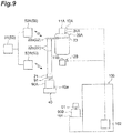
- the controller 50 controls operations of the overhead conveyance vehicles 20A and 20B such that the overhead conveyance vehicle 20A places the FOUP 90A onto the corresponding storage shelf 40. Subsequently, as depicted in FIG. 10 and FIG. 11 , the controller 50 controls operations of the overhead conveyance vehicles 20A and 20B such that the overhead conveyance vehicle 20A receives the FOUP 90B from the device port 101. Subsequently, as depicted in FIG. 12 , the controller 50 controls operations of the overhead conveyance vehicles 20A and 20B such that the overhead conveyance vehicle 20A travels from the transfer region R toward the next destination. Subsequently, as depicted in FIG. 13 and FIG.
- the controller 50 controls operations of the overhead conveyance vehicles 20A and 20B such that the overhead conveyance vehicle 20B having reached the transfer region R receives the FOUP 90A from the storage shelf 40. Subsequently, as depicted in FIG. 15 , the controller 50 controls operations of the overhead conveyance vehicles 20A and 20B such that the overhead conveyance vehicle 20B places the FOUP 90A received from the storage shelf 40 onto the device port 101.
- the controller 50 acquires an expected time for the one overhead conveyance vehicle to reach the transfer region R and, when the expected time is shorter than a predetermined time, performs control such that the overhead conveyance vehicle waits in the transfer region R until the one overhead conveyance vehicle reaches the transfer region R and receives the FOUP 90 from the device port 101.
- the controller 50 acquires the expected time for the one overhead conveyance vehicle to reach the transfer region R and, when the expected time is longer than the predetermined time, performs control such that the other overhead conveyance vehicle places the other FOUP 90 onto the storage shelf 40 and receives the FOUP 90 from the device port 101.
- the controller 50 acquires an expected time from when the overhead conveyance vehicle 20A has reached the transfer region R (see FIG. 1 ) corresponding to the device port 101 before the overhead conveyance vehicle 20B did until when the overhead conveyance vehicle 20B reaches the transfer region. More specifically, in response to an inquiry from the corresponding local controller 52A, the host controller 51 calculates the expected time. Subsequently, the controller 50 determines whether the expected time is equal to or shorter than the predetermined time. Subsequently, the controller 50 performs the first reserving control if having determined that the expected time is equal to or shorter than the predetermined time, and performs the second reserving control if having determined that the expected time is longer than the predetermined time.
- interlocking control described below can be performed.
- first interlocking control when both of overhead conveyance vehicles 20A and 20B are to transfer FOUPs 90 to or from the same device port 101, the controller 50 permits transfer operation performed by one overhead conveyance vehicle thereof, and prohibits transfer operation performed by the other overhead conveyance vehicle during the permitted transfer operation.
- the controller 50 performs communication between the host controller 51 and the local controllers 52A and 52B.
- the controller 50 permits only either one of the overhead conveyance vehicles 20A and 20B to communicate with the device controller 102. Consequently, to the overhead conveyance vehicle that has not been permitted to communicate with the device controller 102, transfer permission will not be given from the device controller 102.
- the controller 50 does not necessarily have to permit an overhead conveyance vehicle that has reached the transfer region R earlier among the overhead conveyance vehicles 20A and 20B to communicate with the device controller 102.
- the controller 50 controls operations of the overhead conveyance vehicles 20A and 20B so as to prohibit the device port-side transfer operation from being performed by the overhead conveyance vehicle 20B.
- the controller 50 controls operations of the overhead conveyance vehicles 20A and 20B so as to prohibit the gripping unit 21 of the overhead conveyance vehicle 20B from being moved to above the device port 101 onto which transfer is to be performed by the movement mechanism 23.
- the following describes second interlocking control.
- the controller 50 permits transfer operation performed by one overhead conveyance vehicle thereof, and prohibits transfer operation performed by the other overhead conveyance vehicle during the permitted transfer operation.
- the controller 50 performs communication between the host controller 51 and the local controllers 52A and 52B.
- the controller 50 permits only either one of the overhead conveyance vehicles 20A and 20B to transfer the FOUP 90 to or from the storage shelf 40.
- the controller 50 does not necessarily have to permit an overhead conveyance vehicle that has reached the transfer region R earlier among the overhead conveyance vehicles 20A and 20B to communicate with the device controller 102.
- the controller 50 controls operations of the overhead conveyance vehicles 20A and 20B so as to prohibit the storage section-side transfer operation from being performed by the overhead conveyance vehicle 20B.
- the controller 50 controls operations of the overhead conveyance vehicles 20A and 20B so as to prohibit the gripping unit 21 of the overhead conveyance vehicle 20B from being moved to above the storage shelf 40 onto which transfer is to be performed by the movement mechanism 23.
- both overhead conveyance vehicles of an overhead conveyance vehicle 20A on the first track 11A and an overhead conveyance vehicle 20B on the second track 11B can transfer FOUPs 90 not only to or from the same device port 101 but also to or from the same storage shelf 40.
- This enables operation to be performed in which, for example, a FOUP 90 that has been placed on the storage shelf 40 by one overhead conveyance vehicle of an overhead conveyance vehicle 20A on the first track 11A and an overhead conveyance vehicle 20B on the second track 11B is received from the storage shelf 40 and is placed onto the device port 101 by the other overhead conveyance vehicle.
- efficiency of conveying FOUPs 90 to or from the device port 101 can be improved.
- the conveyance system 1 further includes the controller 50 configured to control operations of the overhead conveyance vehicles 20A and 20B.
- the controller 50 prohibits the device port-side transfer operation performed by the other.
- the controller prohibits the storage section-side transfer operation performed by the other.
- This control can reliably prevent both overhead conveyance vehicles of overhead conveyance vehicles 20A and 20B from simultaneously performing the device port-side transfer operations of transferring FOUPs 90 to the same device port 101, and also prevent both overhead conveyance vehicles of overhead conveyance vehicles 20A and 20B from simultaneously performing the storage section-side transfer operations of transferring FOUPs 90 to the same storage shelf 40.
- the conveyance system 1 further includes the controller 50 configured to control operations of the overhead conveyance vehicles 20A and 20B.
- the controller 50 controls operations of the overhead conveyance vehicles 20A and 20B such that the overhead conveyance vehicle 20A waits in the transfer region R until the overhead conveyance vehicle 20B reaches the transfer region R and receives the FOUP 90B to be collected from the device port 101, controls operations of the overhead conveyance vehicles 20A and 20B such that the overhead conveyance vehicle 20B having reached the transfer region R receives the FOUP 90B to be collected from the device port 101 while
- the FOUP 90B to be collected can be received from the device port 101, and the FOUP 90A to be delivered can be placed onto the device port 101.
- the controller 50 acquires an expected time for the overhead conveyance vehicle 20B to reach the transfer region R and, when the expected time is equal to or shorter than a predetermined time, controls operations of the overhead conveyance vehicles 20A and 20B such that the overhead conveyance vehicle 20A waits in the transfer region R until the overhead conveyance vehicle 20B reaches the transfer region R and receives the FOUP 90B to be collected from the device port 101.
- the period of time until the overhead conveyance vehicle 20B reaches the transfer region R can be objectively determined, and congestion on the first track 11A on which the overhead conveyance vehicle 20A is positioned can be more reliably prevented from occurring.
- the conveyance system 1 further includes the controller 50 configured to control operations of the overhead conveyance vehicles 20A and 20B.
- the controller 50 controls operations of the overhead conveyance vehicles 20A and 20B such that the overhead conveyance vehicle 20A places the FOUP 90A to be delivered onto the corresponding storage shelf 40 and receives the FOUP 90B to be collected from the device port 101, and controls operations of the overhead conveyance vehicles 20A and 20B such that the overhead conveyance vehicle 20B having reached the transfer region R receives the FOUP 90A to be delivered from the storage shelf 40 and places the FOUP 90
- the FOUP 90B to be collected can be received from the device port 101, and the FOUP 90A to be delivered can be placed onto the device port 101.
- the controller 50 acquires an expected time for the overhead conveyance vehicle 20B to reach the transfer region R and, when the expected time is longer than a predetermined time, controls operations of the overhead conveyance vehicles 20A and 20B such that the overhead conveyance vehicle 20A places the FOUP 90A to be delivered onto the storage shelf 40 and receives the FOUP 90B to be collected from the device port 101.
- the period of time until the overhead conveyance vehicle 20B reaches the transfer region R can be objectively determined, and congestion on the first track 11A on which the overhead conveyance vehicle 20A is positioned can be more reliably prevented from occurring.
- first track 11A and the second track 11B may be configured to be capable of being mutually used by the overhead conveyance vehicles 20A and 20B.
- the embodiment has been described in which, in the reserving control, the overhead conveyance vehicle 20B is an empty vehicle, the overhead conveyance vehicle 20A is a full vehicle, and the overhead conveyance vehicle 20A reaches the transfer region R of the device port 101 before the overhead conveyance vehicle 20B did.
- the overhead conveyance vehicle 20A may be an empty vehicle
- the overhead conveyance vehicle 20B may be a full vehicle
- the overhead conveyance vehicle 20B may reach the transfer region R of the device port 101 before the overhead conveyance vehicle 20A did.
- reserving control is performed that is the same as the reserving control described except that the tracks on which the overhead conveyance vehicle in a full state and the overhead traveling vehicle in an empty state travel change places.
- the method for the controller 50 to acquire the expected time from when the overhead conveyance vehicle 20A in a full state has reached the transfer region R until when the overhead conveyance vehicle 20B in an empty state reaches the transfer region R in the embodiment is not limited to the method for the host controller 51 to calculate the expected time.
- the controller 50 may make an inquiry to a higher-level controller, and may receive information on the expected time from the higher controller.
- the controller 50 performs the first reserving control if having determined that the expected time is equal to or shorter than the predetermined time, and performs the second reserving control if having determined that the expected time is longer than the predetermined time.
- the controller may perform the first reserving control if having determined that the expected time is shorter than the predetermined time, and may perform the second reserving control if having determined that the expected time is equal to or longer than the predetermined time.
- the controller 50 receives the expected time, performs the first reserving control if having determined that the expected time is equal to or shorter than the predetermined time, and performs the second reserving control if having determined that the expected time is longer than the predetermined time.
- the controller 50 may perform the second reserving control at the time when the overhead conveyance vehicle 20A has reached the transfer region R without acquiring the expected time. In other words, the controller may prefer performing the second reserving control over performing the first reserving control.
- the overhead conveyance vehicle 20A may be caused to wait for a predetermined time (e.g., 10 seconds) after reaching the transfer region R, and the second reserving control may be performed if the overhead conveyance vehicle 20B does not reach the transfer region R during a period when the overhead conveyance vehicle 20A is waiting in the transfer region R.
- a predetermined time e.g. 10 seconds
- operations of the overhead conveyance vehicles 20A and 20B may be controlled such that the overhead conveyance vehicle 20B starts the next operation (e.g. , operation of placing a FOUP 90A on a storage shelf 40, or operation of circling one round on a track while holding the FOUP 90A).
- the controller 50 controls operations of the overhead conveyance vehicles 20A and 20B such that the device port-side transfer operation or the storage section-side transfer operation is prohibited from being performed by the overhead conveyance vehicle 20B during a period when the device port-side transfer operation or the storage section-side transfer operation is being performed by the overhead conveyance vehicle 20A.
- the controller 50 may control operations of the overhead conveyance vehicles 20A and 20B such that the device port-side transfer operation or the storage section-side transfer operation is prohibited from being performed by the overhead conveyance vehicle 20A during a period when the device port-side transfer operation or the storage section-side transfer operation is being performed by the overhead conveyance vehicle 20B.
- control may be performed by the local controllers 52A and 52B without the host controller 51 being involved.
- the local controllers 52A and 52B may communicate with each other, and the overhead conveyance vehicles 20A and 20B may be controlled by the local controllers 52A and 52B.
- a third track may be provided in such a position that the third track coincides with the first track and the second track when viewed from the vertical direction.
- three tracks may be arranged parallel in the vertical direction.
- the third track may be provided along the first track 11A and the second track 11B and arranged below and parallel with the second track 11B in the vertical direction such that the device ports 101 are positioned below and on the one side of the third track.
- the reserving control and the interlocking control described above can be used in the same manner as in the embodiment.
- four or more tracks may be arranged parallel in the vertical direction. Also in this configuration, the reserving control and the interlocking control described above can be used in the same manner as in the embodiment.
- conveyed objects conveyed by the conveyance system of the present invention are not limited to FOUPs 90 in each of which a plurality of semiconductor wafers are accommodated, and may be other containers in each of which glass wafers, reticles, or the like are accommodated.
- the conveyance system of the present invention can be used not only in the semiconductor manufacturing plant, but also in other facilities.
Landscapes
- Engineering & Computer Science (AREA)
- Physics & Mathematics (AREA)
- Condensed Matter Physics & Semiconductors (AREA)
- General Physics & Mathematics (AREA)
- Manufacturing & Machinery (AREA)
- Computer Hardware Design (AREA)
- Microelectronics & Electronic Packaging (AREA)
- Power Engineering (AREA)
- Mechanical Engineering (AREA)
- Container, Conveyance, Adherence, Positioning, Of Wafer (AREA)
- Warehouses Or Storage Devices (AREA)
Abstract
Description
- One aspect of the present invention relates to a conveyance system.
- As a conveyance system used in a semiconductor manufacturing plant, for example, a conveyance system including: a first track and a second track arranged parallel in the vertical direction; overhead conveyance vehicles configured to travel along each of the first track and the second track; and storage shelves provided beside each of the first track and the second track is known (see
Patent Literature 1, for example). - [Patent Literature 1] Japanese Unexamined Patent Publication No.
2007-331906 - From the viewpoint of improving the operation rate of semiconductor processing devices, the conveyance system described above is required to prevent congestion of overhead conveyance vehicles to efficiently convey conveyed objects to or from device ports of the semiconductor processing devices.
- In view of this, one aspect of the present invention aims to provide a conveyance system that can improve efficiency of conveying conveyed objects to or from device ports.
- A conveyance system according to one aspect of the present invention includes: a first track provided such that a device port is positioned below and on one side of the first track; a second track provided along the first track and arranged below and parallel with the first track in a vertical direction such that the device port is positioned below and on the one side of the second track; a plurality of overhead conveyance vehicles configured to travel along each of the first track and the second track, and each of the plurality of overhead conveyance vehicles configured to convey a conveyed object; and a storage section provided below and on the other side of the first track and the second track, the other side opposed to the one side of the first track and the second track, and configured to have the conveyed object placed thereon. Each overhead conveyance vehicle includes: a gripping unit capable of gripping the conveyed object; a movement mechanism capable of moving the gripping unit to a position above the device port or above the storage section; and a hoisting mechanism capable of raising and lowering, with respect to the device port of the storage section, the gripping unit, which has been moved to the position above the device port or above the storage section by the movement mechanism.
- In this conveyance system, both overhead conveyance vehicles of an overhead conveyance vehicle on the first track and an overhead conveyance vehicle on the second track can transfer conveyed objects not only to or from the same device port but also to or from the same storage section. This enables operation to be performed in which, for example, a conveyed object that has been placed on the storage section by one overhead conveyance vehicle of an overhead conveyance vehicle on the first track and an overhead conveyance vehicle on the second track is received from the storage section and is placed onto the device port by the other overhead conveyance vehicle. Thus, with this conveyance system, efficiency of conveying conveyed objects to or from the device port can be improved.
- The conveyance system according to one aspect of the present invention may further include a controller configured to control operations of the overhead conveyance vehicles. In a situation in which one of the overhead conveyance vehicles on the first track and one of the overhead conveyance vehicles on the second track need to perform device port-side transfer operations of transferring the conveyed objects to or from the same device port, during the device port-side transfer operation performed by one of the overhead conveyance vehicles on the first track and on the second track, the controller may prohibit the other one of the overhead conveyance vehicles from performing the device port-side transfer operation. In a situation in which one of the overhead conveyance vehicles on the first track and one of the overhead conveyance vehicles on the second track need to perform storage section-side transfer operations of transferring the conveyed objects to or from the same storage section, during the storage section-side transfer operation performed by one of the overhead conveyance vehicles on the first track and on the second track, the controller may prohibit the other one of the overhead conveyance vehicles from performing the storage section-side transfer operation . This control can reliably prevent both overhead conveyance vehicles of an overhead conveyance vehicle on the first track and an overhead conveyance vehicle on the second track from simultaneously performing the device port-side transfer operations of transferring the conveyed objects to the same device port, and also prevent both overhead conveyance vehicles of an overhead conveyance vehicle on the first track and an overhead conveyance vehicle on the second track from simultaneously performing the storage section-side transfer operations of transferring the conveyed objects to the same storage section.
- The conveyance system according to one aspect of the present invention may further include a controller configured to control operations of the overhead conveyance vehicles. With respect to the same device port, in a situation in which one of the overhead conveyance vehicles on the first track and on the second track needs to receive from the device port the conveyed object to be collected from the device port, and the other one of the overhead conveyance vehicles on the first track and on the second track needs to place onto the device port the conveyed object to be delivered to the device port, when the other overhead conveyance vehicle has reached a transfer region corresponding to the device port before the one overhead conveyance vehicle reached the transfer region, the controller may control operations of the overhead conveyance vehicles such that the other overhead conveyance vehicle waits in the transfer region until the one overhead conveyance vehicle reaches the transfer region and receives the conveyed object to be collected from the device port, control operations of the overhead conveyance vehicles such that the one overhead conveyance vehicle having reached the transfer region receives the conveyed object to be collected from the device port while the other overhead conveyance vehicle is waiting in the transfer region, and control operations of the overhead conveyance vehicles such that the other overhead conveyance vehicle places the conveyed object to be delivered onto the device port after the one overhead conveyance vehicle receives the conveyed object to be collected from the device port. By this control, for example, when a period of time until the one overhead conveyance vehicle reaches the transfer region is relatively short, while congestion is prevented from occurring on a track on which the other overhead conveyance vehicle is positioned, the conveyed object to be collected can be received from the device port, and the conveyed object to be delivered can be placed onto the device port.
- In the conveyance system according to one aspect of the present invention, the controller may acquire an expected time for the one overhead conveyance vehicle to reach the transfer region and, when the expected time is shorter than a predetermined time, may control operations of the overhead conveyance vehicles such that the other overhead conveyance vehicle waits in the transfer region until the one overhead conveyance vehicle reaches the transfer region and receives the conveyed object to be collected from the device port. By this control, the period of time until the one overhead conveyance vehicle reaches the transfer region can be objectively determined, and congestion on a track on which the other overhead conveyance vehicle is positioned can be more reliably prevented from occurring.
- The conveyance system according to one aspect of the present invention may further include a controller configured to control operations of the overhead conveyance vehicles. With respect to the same device port, in a situation in which one of the overhead conveyance vehicles on the first track and on the second track needs to receive from the device port the conveyed object to be collected from the device port, and the other one of the overhead conveyance vehicles on the first track and on the second track needs to place onto the device port the conveyed object to be delivered to the device port, when the other overhead conveyance vehicle has reached a transfer region corresponding to the device port before the one overhead conveyance vehicle reached the transfer region, the controller may control operations of the overhead conveyance vehicles such that the other overhead conveyance vehicle places the conveyed object to be delivered onto the storage section and receives the conveyed object to be collected from the device port, and control operations of the overhead conveyance vehicles such that the one overhead conveyance vehicle having reached the transfer region receives the conveyed object to be delivered from the storage section and places the conveyed object to be delivered onto the device port. By this control, for example, when a period of time until the one overhead conveyance vehicle reaches the transfer region is relatively long, while congestion is prevented from occurring on a track on which the other overhead conveyance vehicle is positioned, the conveyed object to be collected can be received from the device port, and the conveyed object to be delivered can be placed onto the device port.
- In the conveyance system according to one aspect of the present invention, the controller may acquire an expected time for the one overhead conveyance vehicle to reach the transfer region and, when the expected time is longer than a predetermined time, may control operations of the overhead conveyance vehicles such that the other overhead conveyance vehicle places the conveyed object to be delivered onto the storage section and receives the conveyed object to be collected from the device port. By this control, the period of time until the one overhead conveyance vehicle reaches the transfer region can be objectively determined, and congestion on a track on which the other overhead conveyance vehicle is positioned can be more reliably prevented from occurring.
- One aspect of the present invention can provide a conveyance system that can improve efficiency of conveying conveyed objects to or from device ports.
-
-
FIG. 1 is a plan view of a conveyance system according to one embodiment of the present invention. -
FIG. 2 is a front view of part of the conveyance system inFIG. 1 . -
FIG. 3 is a diagram for explaining first reserving control in the conveyance system inFIG. 1 . -
FIG. 4 is a diagram for explaining the first reserving control in the conveyance system inFIG. 1 . -
FIG. 5 is a diagram for explaining the first reserving control in the conveyance system inFIG. 1 . -
FIG. 6 is a diagram for explaining the first reserving control in the conveyance system inFIG. 1 . -
FIG. 7 is a diagram for explaining the first reserving control in the conveyance system inFIG. 1 . -
FIG. 8 is a diagram for explaining second reserving control in the conveyance system inFIG. 1 . -
FIG. 9 is a diagram for explaining the second reserving control in the conveyance system inFIG. 1 . -
FIG. 10 is a diagram for explaining the second reserving control in the conveyance system inFIG. 1 . -
FIG. 11 is a diagram for explaining the second reserving control in the conveyance system inFIG. 1 . -
FIG. 12 is a diagram for explaining the second reserving control in the conveyance system inFIG. 1 . -
FIG. 13 is a diagram for explaining the second reserving control in the conveyance system inFIG. 1 . -
FIG. 14 is a diagram for explaining the second reserving control in the conveyance system inFIG. 1 . -
FIG. 15 is a diagram for explaining the second reserving control in the conveyance system inFIG. 1 . -
FIG. 16 is a diagram for explaining first interlocking control in the conveyance system inFIG. 1 . -
FIG. 17 is a diagram for explaining the first interlocking control in the conveyance system inFIG. 1 . -
FIG. 18 is a diagram for explaining second interlocking control in the conveyance system inFIG. 1 . -
FIG. 19 is a diagram for explaining the second interlocking control in the conveyance system inFIG. 1 . - A preferred embodiment of the present invention will now be described in detail with reference to the drawings. Similar or equivalent elements are designated by similar reference signs in each drawing, and duplicate explanation is omitted.
- As depicted in
FIG. 1 andFIG. 2 , aconveyance system 1 includestracks overhead conveyance vehicles storage shelves 40, and acontroller 50. Thetracks semiconductor processing devices 100. Theoverhead conveyance vehicles tracks tracks overhead conveyance vehicles tracks track 10A are called overhead conveyance vehicles (first overhead conveyance vehicles) 20A, and overhead conveyance vehicles that travel along thetrack 10B are called overhead conveyance vehicles (second overhead conveyance vehicles) 20B. Theoverhead conveyance vehicles device port 101 of eachsemiconductor processing device 100. Thestorage shelves 40 are disposed so as to correspond to the respectivesemiconductor processing devices 100. For example, in the extending direction of thetracks device port 101 of eachsemiconductor processing device 100, at least onestorage shelf 40 is disposed. Thestorage shelf 40 is disposed at the same position as thedevice port 101 of eachsemiconductor processing device 100 in the extending direction of thetracks storage shelf 40 corresponding to eachsemiconductor processing device 100 is disposed upstream (upstream in a direction in which theoverhead conveyance vehicles device port 101 of thesemiconductor processing device 100 in the extending direction of thetracks controller 50 controls operations of theoverhead conveyance vehicles - The
tracks inter-bay routes intra-bay routes tracks overhead conveyance vehicles inter-bay routes intra-bay routes tracks intra-bay routes - In the
conveyance system 1, part of the intra-bay route 14A forms afirst track 11A, and part of theintra-bay route 14B forms asecond track 11B. Thefirst track 11A and thesecond track 11B are formed with straight portions provided in theintra-bay routes second track 11B is provided along thefirst track 11A. In other words, thefirst track 11A and thesecond track 11B are provided parallel such that directions in whichoverhead conveyance vehicles 20 travel on the tracks are the same direction. Thesecond track 11B is provided below (directly below) thefirst track 11A and arranged parallel with thefirst track 11A in the vertical direction. Specifically, as depicted inFIG. 2 , for example, thesecond track 11B is provided so as to be arranged below and parallel with thefirst track 11A in the vertical direction in such a position that thefirst track 11A and thesecond track 11B coincide with each other when viewed from the vertical direction. On side surfaces of thefirst track 11A and thesecond track 11B, a plurality oftransceiver units overhead conveyance vehicles FIG. 3 ). - The
device ports 101 are disposed outside of theintra-bay routes intra-bay routes first track 11A and thesecond track 11B extend. When thefirst track 11A and thesecond track 11B each in a pair are focused on, thedevice ports 101 are provided so as to be positioned below and on one side of thefirst track 11A and thesecond track 11B that are arranged parallel in the vertical direction. - The
device ports 101, onto which FOUPs 90 that are objects to be conveyed by theoverhead conveyance vehicles FOUPs 90 to the correspondingsemiconductor processing devices 100. When semiconductor wafers accommodated in theFOUPs 90 are processed by thesemiconductor processing devices 100, thedevice ports 101 transfer theFOUPs 90 from thesemiconductor processing devices 100, and thus have theFOUPs 90 placed thereon. - Operation of each
semiconductor processing device 100 is controlled by a device controller 102 (seeFIG. 3 ). Thedevice controller 102 communicates withoverhead conveyance vehicles overhead conveyance vehicles FOUPs 90 todevice ports 101. In the present embodiment, transferringFOUPs 90 todevice ports 101 includes a case thatoverhead conveyance vehicles device ports 101 and a case thatoverhead conveyance vehicles device ports 101. In the present embodiment, transferringFOUPs 90 tostorage shelves 40 includes a case thatoverhead conveyance vehicles FOUPs 90 tostorage shelves 40 and a case thatoverhead conveyance vehicles FOUPs 90 placed onstorage shelves 40. - On the
storage shelves 40,FOUPs 90 are each placed. In other words, thestorage shelves 40support FOUPs 90. A region on eachstorage shelf 40 functions as astorage section 40a on which aFOUP 90 can be placed. Thestorage section 40a is a temporary storage region onto whichoverhead conveyance vehicles first track 11A and thesecond track 11B can transfer aFOUP 90. - When the
first track 11A and thesecond track 11B each in a pair are focused on, thestorage shelves 40 are provided below and on the other side of thefirst track 11A and thesecond track 11B opposed to the one side thereof on which thedevice ports 101 are provided. In other words, when viewed from the vertical direction, thestorage shelves 40 are provided on the side opposed to thedevice ports 101 with thefirst track 11A and thesecond track 11B interposed therebetween. Thedevice ports 101 are provided inside theintra-bay routes device ports 101 are provided along the direction in which thefirst track 11A and thesecond track 11B extend, and are provided below thesecond track 11B in the vertical direction. - As described above, the
conveyance system 1 includes: thefirst track 11A and thesecond track 11B that are arranged parallel in the vertical direction such that thedevice ports 101 are positioned below and on the one side of both tracks; the overhead conveyance vehicles (first overhead conveyance vehicles) 20A and the overhead conveyance vehicles (second overhead conveyance vehicles) 20B configured to travel along thefirst track 11A and thesecond track 11B, respectively, and conveyFOUPs 90; and thestorage shelves 40 provided below and on the other side of thefirst track 11A and thesecond track 11B opposed to the one side thereof, and configured such thatFOUPs 90 are placed thereon. - Each
overhead conveyance vehicle 20A travels along thefirst track 11A to convey aFOUP 90. Eachoverhead conveyance vehicle 20B travels along thesecond track 11B to convey aFOUP 90. Theoverhead conveyance vehicles FOUPs 90, for example, betweendevice ports storage shelves device port 101 and astorage shelf 40. - The
overhead conveyance vehicles FOUP 90 to or from adevice port 101 and astorage shelf 40. The conveyed-object transfer mechanism includes a grippingunit 21, ahoisting mechanism 22, and amovement mechanism 23. Theoverhead conveyance vehicles transceiver units - The gripping
unit 21 is a device configured to grip and release aflange portion 91 of aFOUP 90. The grippingunit 21 can grip theflange portion 91 of theFOUP 90. When each of theoverhead conveyance vehicles FOUP 90 from adevice port 101 and astorage shelf 40, the corresponding grippingunit 21 grips theflange portion 91 of theFOUP 90. The grippingunit 21 releases theflange portion 91 of theFOUP 90 when each of theoverhead conveyance vehicles FOUP 90 onto adevice port 101 and astorage shelf 40. - The
hoisting mechanism 22 is a device configured to raise and lower the grippingunit 21 in the vertical direction. Thehoisting mechanism 22 can raise and lower the grippingunit 21 in the vertical direction. Thehoisting mechanism 22 includes a windingmechanism 22a and abelt 22b. The windingmechanism 22a is supported by themovement mechanism 23. The windingmechanism 22a is a device configured to wind up and wind down thebelt 22b in the vertical direction. The windingmechanism 22a can wind up and wind down thebelt 22b in the vertical direction. Thebelt 22b is suspended from the windingmechanism 22a, and supports the grippingunit 21 at the lower end thereof. Thehoisting mechanism 22 can raise and lower aFOUP 90 gripped by the grippingunit 21 for a distance at least allowing theFOUP 90 to reach thedevice port 101 and thestorage shelf 40. - The
movement mechanism 23 is a device configured to move the grippingunit 21 and thehoisting mechanism 22 from each of theoverhead conveyance vehicles unit 21 and thehoisting mechanism 22 from each of theoverhead conveyance vehicles movement mechanism 23 can move the grippingunit 21 and thehoisting mechanism 22 from each of theoverhead conveyance vehicles overhead conveyance vehicles movement mechanism 23 can move the grippingunit 21 and thehoisting mechanism 22 to above each of thedevice port 101 and thestorage shelf 40. When aFOUP 90 is gripped by the grippingunit 21, themovement mechanism 23 can move theFOUP 90 to or from above thedevice port 101 and thestorage shelf 40 in the vertical direction. - Each of the
overhead conveyance vehicles first track 11A and thesecond track 11B, respectively, can transfer aFOUP 90 to or from both adevice port 101 and astorage shelf 40 that are positioned beside and below thefirst track 11A and thesecond track 11B. In other words, anoverhead conveyance vehicle 20A and anoverhead conveyance vehicle 20B can transferFOUPs 90 to or from thesame device port 101 and thesame storage shelf 40. Thus, both theoverhead conveyance vehicle 20A on thefirst track 11A and theoverhead conveyance vehicle 20B on thesecond track 11B can deliver and receive (transfer) FOUPs 90 to or from thedevice port 101. Furthermore, both theoverhead conveyance vehicle 20A on thefirst track 11A and theoverhead conveyance vehicle 20B on thesecond track 11B can deliver and receiveFOUPs 90 to or from thestorage shelf 40. In other words, eachstorage shelf 40 includes astorage section 40a that is shared by anoverhead conveyance vehicle 20A traveling on thefirst track 11A and anoverhead conveyance vehicle 20B traveling on thesecond track 11B. - Specifically, each of the
overhead conveyance vehicles gripping unit 21 grips theflange portion 91 of aFOUP 90 directly below thefirst track 11A and thesecond track 11B, causes thecorresponding movement mechanism 23 to operate to move theFOUP 90 to above each of thedevice port 101 and thestorage shelf 40. Subsequently, each of theoverhead conveyance vehicles mechanism 22a to operate to wind down thebelt 22b, thereby lowering theFOUP 90 to place theFOUP 90 onto thedevice port 101 or onto thestorage shelf 40. As described above, each of theoverhead conveyance vehicles FOUP 90 to thedevice port 101 and thestorage shelf 40. - Each of the
overhead conveyance vehicles unit 21 to grip theflange portion 91 of theFOUP 90 placed on thedevice port 101 or on thestorage shelf 40. Subsequently, each of theoverhead conveyance vehicles mechanism 22a to operate to wind up thebelt 22b, thereby raising theFOUP 90. Subsequently, each of theoverhead conveyance vehicles movement mechanism 23 to operate to move theFOUP 90 to directly below thefirst track 11A and thesecond track 11B. As described above, each of theoverhead conveyance vehicles FOUP 90 from thedevice port 101 or thestorage shelf 40. - The
transceiver units overhead conveyance vehicles FIG. 3 ). Thetransceiver unit 24A can communicate with thetransceiver units 12A provided to thefirst track 11A. Thetransceiver units transceiver unit 24B can communicate with thetransceiver units 12B provided to thesecond track 11B. Thetransceiver units overhead conveyance vehicles transceiver units transceiver units device controller 102 via thetransceiver units - The
controller 50 controls operations of theoverhead conveyance vehicles controller 50 includeslocal controllers overhead conveyance vehicles host controller 51 configured to communicate with the respectivelocal controllers local controllers FIG. 3 ) . Areas under control of the respectivelocal controllers semiconductor processing devices 100. The method of dividing the areas under control of the respectivelocal controllers - In the
conveyance system 1 configured as described above, for example, reserving control described below can be performed. The transfer region R for eachdevice port 101 in the following description means a region where, on thefirst track 11A and on thesecond track 11B,overhead conveyance vehicles FOUP 90 to thedevice port 101. The transfer region R for eachdevice port 101 is a region that is, on thefirst track 11A and on thesecond track 11B, at the same position as thedevice port 101 and thecorresponding storage shelf 40 in the direction along each of thefirst track 11A and thesecond track 11B. Alternatively, in a mode in which thestorage shelf 40 corresponding to eachdevice port 101 is provided upstream of thedevice port 101 in this direction, the transfer region R for thedevice port 101 includes a region that is at the same position as thestorage shelf 40 corresponding to thedevice port 101 in the direction. - First reserving control will be described first. In the first reserving control, with respect to the
same device port 101, if one overhead conveyance vehicle ofoverhead conveyance vehicles FOUP 90 from thedevice port 101 and the other overhead conveyance vehicle is to place anotherFOUP 90 onto thedevice port 101 having become empty, when the other overhead conveyance vehicle has reached a transfer region R corresponding to thedevice port 101 before the one overhead conveyance vehicle did, thecontroller 50 performs control such that the other overhead conveyance vehicle waits in the transfer region R until the one overhead conveyance vehicle reaches the transfer region R and receives theFOUP 90 from thedevice port 101, performs control such that the one overhead conveyance vehicle having reached the transfer region R receives theFOUP 90 from thedevice port 101 while the other overhead conveyance vehicle is waiting in the transfer region R, and performs control such that the other overhead conveyance vehicle places theother FOUP 90 onto thedevice port 101 after the one overhead conveyance vehicle receives theFOUP 90 from thedevice port 101. - Specifically, as depicted in
FIG. 3 , for example, with respect to thesame device port 101, in a situation in which anoverhead conveyance vehicle 20B (i.e., an empty vehicle) that is not loaded with a FOUP 90 (that is in an empty state) needs to receive aFOUP 90B that is aFOUP 90 to be collected from thedevice port 101 from thedevice port 101, and anoverhead conveyance vehicle 20A (i.e., a full vehicle) that is loaded with a FOUP 90 (that is in a full state) needs to place thisFOUP 90A that is aFOUP 90 to be delivered to thedevice port 101 onto thedevice port 101, when theoverhead conveyance vehicle 20A has reached a transfer region R (seeFIG. 1 ) corresponding to thedevice port 101 before theoverhead conveyance vehicle 20B did, thecontroller 50 controls operations of theoverhead conveyance vehicles overhead conveyance vehicle 20A waits in the transfer region R until theoverhead conveyance vehicle 20B reaches the transfer region R and receives theFOUP 90B from thedevice port 101. Subsequently, as depicted inFIG. 4 andFIG. 5 , thecontroller 50 controls operations of theoverhead conveyance vehicles overhead conveyance vehicle 20B having reached the transfer region R receives theFOUP 90B from thedevice port 101. Subsequently, as depicted inFIG. 6 , thecontroller 50 controls the operations of theoverhead conveyance vehicles overhead conveyance vehicle 20B travels from the transfer region R toward the next destination. Subsequently, as depicted inFIG. 7 , thecontroller 50 controls operations of theoverhead conveyance vehicles overhead conveyance vehicle 20A places theFOUP 90A onto thedevice port 101. - The following describes second reserving control. In the second reserving control, with respect to the
same device port 101, if one overhead conveyance vehicle ofoverhead conveyance vehicles FOUP 90 from thedevice port 101 and the other overhead conveyance vehicle is to place anotherFOUP 90 onto thedevice port 101 having become empty onto thedevice port 101, when the other overhead conveyance vehicle has reached a transfer region R corresponding to thedevice port 101 before the one overhead conveyance vehicle did, thecontroller 50 performs control such that the other overhead conveyance vehicle places theother FOUP 90 onto the correspondingstorage shelf 40 and receives theFOUP 90 from thedevice port 101, and performs control such that the one overhead conveyance vehicle having reached the transfer region R receives theother FOUP 90 from thestorage shelf 40 and places theother FOUP 90 onto thedevice port 101. - Specifically, as depicted in
FIG. 8 andFIG. 9 , for example, with respect to thesame device port 101, in a situation in which anoverhead conveyance vehicle 20B in an empty state needs to receive aFOUP 90B that is aFOUP 90 to be collected from thedevice port 101 from thedevice port 101, and anoverhead conveyance vehicle 20A in a full state needs to place aFOUP 90A that is aFOUP 90 to be delivered to thedevice port 101 onto thedevice port 101, when theoverhead conveyance vehicle 20A has reached a transfer region R (seeFIG. 1 ) corresponding to thedevice port 101 before theoverhead conveyance vehicle 20B did, thecontroller 50 controls operations of theoverhead conveyance vehicles overhead conveyance vehicle 20A places theFOUP 90A onto the correspondingstorage shelf 40. Subsequently, as depicted inFIG. 10 andFIG. 11 , thecontroller 50 controls operations of theoverhead conveyance vehicles overhead conveyance vehicle 20A receives theFOUP 90B from thedevice port 101. Subsequently, as depicted inFIG. 12 , thecontroller 50 controls operations of theoverhead conveyance vehicles overhead conveyance vehicle 20A travels from the transfer region R toward the next destination. Subsequently, as depicted inFIG. 13 andFIG. 14 , thecontroller 50 controls operations of theoverhead conveyance vehicles overhead conveyance vehicle 20B having reached the transfer region R receives theFOUP 90A from thestorage shelf 40. Subsequently, as depicted inFIG. 15 , thecontroller 50 controls operations of theoverhead conveyance vehicles overhead conveyance vehicle 20B places theFOUP 90A received from thestorage shelf 40 onto thedevice port 101. - In the
conveyance system 1, thecontroller 50 acquires an expected time for the one overhead conveyance vehicle to reach the transfer region R and, when the expected time is shorter than a predetermined time, performs control such that the overhead conveyance vehicle waits in the transfer region R until the one overhead conveyance vehicle reaches the transfer region R and receives theFOUP 90 from thedevice port 101. In theconveyance system 1, thecontroller 50 acquires the expected time for the one overhead conveyance vehicle to reach the transfer region R and, when the expected time is longer than the predetermined time, performs control such that the other overhead conveyance vehicle places theother FOUP 90 onto thestorage shelf 40 and receives theFOUP 90 from thedevice port 101. - Specifically, in the
conveyance system 1, before performing the first reserving control or the second reserving control, thecontroller 50 acquires an expected time from when theoverhead conveyance vehicle 20A has reached the transfer region R (seeFIG. 1 ) corresponding to thedevice port 101 before theoverhead conveyance vehicle 20B did until when theoverhead conveyance vehicle 20B reaches the transfer region. More specifically, in response to an inquiry from the correspondinglocal controller 52A, thehost controller 51 calculates the expected time. Subsequently, thecontroller 50 determines whether the expected time is equal to or shorter than the predetermined time. Subsequently, thecontroller 50 performs the first reserving control if having determined that the expected time is equal to or shorter than the predetermined time, and performs the second reserving control if having determined that the expected time is longer than the predetermined time. - In the
conveyance system 1, for example, interlocking control described below can be performed. - First interlocking control will be described first. In the first interlocking control, when both of
overhead conveyance vehicles FOUPs 90 to or from thesame device port 101, thecontroller 50 permits transfer operation performed by one overhead conveyance vehicle thereof, and prohibits transfer operation performed by the other overhead conveyance vehicle during the permitted transfer operation. - Specifically, as depicted in
FIG. 16 andFIG. 17 , thecontroller 50 performs communication between thehost controller 51 and thelocal controllers same device port 101, in a situation in which both of theoverhead conveyance vehicles FOUPs 90 at the same time, thecontroller 50 permits only either one of theoverhead conveyance vehicles device controller 102. Consequently, to the overhead conveyance vehicle that has not been permitted to communicate with thedevice controller 102, transfer permission will not be given from thedevice controller 102. After the overhead conveyance vehicle that has been permitted to communicate with thedevice controller 102 completes the device port-side transfer operation, the overhead conveyance vehicle that had not been permitted to communicate with thedevice controller 102 is permitted to communicate with thedevice controller 102. Thecontroller 50 does not necessarily have to permit an overhead conveyance vehicle that has reached the transfer region R earlier among theoverhead conveyance vehicles device controller 102. In the illustrated example, during a period when the device port-side transfer operation is being performed by theoverhead conveyance vehicle 20A, thecontroller 50 controls operations of theoverhead conveyance vehicles overhead conveyance vehicle 20B. Specifically, during a period when the grippingunit 21 of theoverhead conveyance vehicle 20A is being moved to above thedevice port 101 onto which transfer is to be performed by themovement mechanism 23, thecontroller 50 controls operations of theoverhead conveyance vehicles unit 21 of theoverhead conveyance vehicle 20B from being moved to above thedevice port 101 onto which transfer is to be performed by themovement mechanism 23. - The following describes second interlocking control. In the second interlocking control, when both of
overhead conveyance vehicles FOUPs 90 to or from thesame storage shelf 40, thecontroller 50 permits transfer operation performed by one overhead conveyance vehicle thereof, and prohibits transfer operation performed by the other overhead conveyance vehicle during the permitted transfer operation. - Specifically, as depicted in
FIG. 18 andFIG. 19 , thecontroller 50 performs communication between thehost controller 51 and thelocal controllers same storage shelf 40, in a situation in which both of theoverhead conveyance vehicles FOUPs 90 at the same time, thecontroller 50 permits only either one of theoverhead conveyance vehicles FOUP 90 to or from thestorage shelf 40. Thecontroller 50 does not necessarily have to permit an overhead conveyance vehicle that has reached the transfer region R earlier among theoverhead conveyance vehicles device controller 102. In the illustrated example, during a period when the storage section-side transfer operation is being performed by theoverhead conveyance vehicle 20A, thecontroller 50 controls operations of theoverhead conveyance vehicles overhead conveyance vehicle 20B. Specifically, during a period when the grippingunit 21 of theoverhead conveyance vehicle 20A is being moved to above thestorage shelf 40 onto which transfer is to be performed by themovement mechanism 23, thecontroller 50 controls operations of theoverhead conveyance vehicles unit 21 of theoverhead conveyance vehicle 20B from being moved to above thestorage shelf 40 onto which transfer is to be performed by themovement mechanism 23. - As described above, in the
conveyance system 1, both overhead conveyance vehicles of anoverhead conveyance vehicle 20A on thefirst track 11A and anoverhead conveyance vehicle 20B on thesecond track 11B can transferFOUPs 90 not only to or from thesame device port 101 but also to or from thesame storage shelf 40. This enables operation to be performed in which, for example, aFOUP 90 that has been placed on thestorage shelf 40 by one overhead conveyance vehicle of anoverhead conveyance vehicle 20A on thefirst track 11A and anoverhead conveyance vehicle 20B on thesecond track 11B is received from thestorage shelf 40 and is placed onto thedevice port 101 by the other overhead conveyance vehicle. Thus, with thisconveyance system 1, efficiency of conveyingFOUPs 90 to or from thedevice port 101 can be improved. - The
conveyance system 1 further includes thecontroller 50 configured to control operations of theoverhead conveyance vehicles overhead conveyance vehicles FOUP 90 to or from thesame device port 101, during the device port-side transfer operation performed by one of theoverhead conveyance vehicles controller 50 prohibits the device port-side transfer operation performed by the other. In a situation in which both ofoverhead conveyance vehicles FOUPs 90 to or from thesame storage shelf 40, during the storage section-side transfer operation performed by one of theoverhead conveyance vehicles overhead conveyance vehicles FOUPs 90 to thesame device port 101, and also prevent both overhead conveyance vehicles ofoverhead conveyance vehicles FOUPs 90 to thesame storage shelf 40. - The
conveyance system 1 further includes thecontroller 50 configured to control operations of theoverhead conveyance vehicles same device port 101, in a situation in which anoverhead conveyance vehicle 20B needs to receive aFOUP 90B that is aFOUP 90 to be collected from thedevice port 101 from thedevice port 101, and anoverhead conveyance vehicle 20A needs to place aFOUP 90A that is aFOUP 90 to be delivered to thedevice port 101 onto thedevice port 101, when theoverhead conveyance vehicle 20A has reached a transfer region R corresponding to thedevice port 101 before theoverhead conveyance vehicle 20B did, thecontroller 50 controls operations of theoverhead conveyance vehicles overhead conveyance vehicle 20A waits in the transfer region R until theoverhead conveyance vehicle 20B reaches the transfer region R and receives theFOUP 90B to be collected from thedevice port 101, controls operations of theoverhead conveyance vehicles overhead conveyance vehicle 20B having reached the transfer region R receives theFOUP 90B to be collected from thedevice port 101 while theoverhead conveyance vehicle 20A is waiting in the transfer region R, and controls operations of theoverhead conveyance vehicles overhead conveyance vehicle 20A places theFOUP 90A to be delivered onto thedevice port 101 after theoverhead conveyance vehicle 20B receives theFOUP 90B to be collected from thedevice port 101. By this control, for example, when a period of time until theoverhead conveyance vehicle 20B reaches the transfer region R is relatively short, while congestion is prevented from occurring on thefirst track 11A on which theoverhead conveyance vehicle 20A is positioned, theFOUP 90B to be collected can be received from thedevice port 101, and theFOUP 90A to be delivered can be placed onto thedevice port 101. - In the
conveyance system 1, thecontroller 50 acquires an expected time for theoverhead conveyance vehicle 20B to reach the transfer region R and, when the expected time is equal to or shorter than a predetermined time, controls operations of theoverhead conveyance vehicles overhead conveyance vehicle 20A waits in the transfer region R until theoverhead conveyance vehicle 20B reaches the transfer region R and receives theFOUP 90B to be collected from thedevice port 101. By this control, the period of time until theoverhead conveyance vehicle 20B reaches the transfer region R can be objectively determined, and congestion on thefirst track 11A on which theoverhead conveyance vehicle 20A is positioned can be more reliably prevented from occurring. - The
conveyance system 1 further includes thecontroller 50 configured to control operations of theoverhead conveyance vehicles same device port 101, in a situation in which anoverhead conveyance vehicle 20B needs to receive aFOUP 90B that is aFOUP 90 to be collected from thedevice port 101 from thedevice port 101 and anoverhead conveyance vehicle 20A needs to place aFOUP 90A that is aFOUP 90 to be delivered to thedevice port 101 onto thedevice port 101, when theoverhead conveyance vehicle 20A has reached a transfer region R corresponding to thedevice port 101 before theoverhead conveyance vehicle 20B did, thecontroller 50 controls operations of theoverhead conveyance vehicles overhead conveyance vehicle 20A places theFOUP 90A to be delivered onto the correspondingstorage shelf 40 and receives theFOUP 90B to be collected from thedevice port 101, and controls operations of theoverhead conveyance vehicles overhead conveyance vehicle 20B having reached the transfer region R receives theFOUP 90A to be delivered from thestorage shelf 40 and places theFOUP 90A to be delivered onto thedevice port 101. By this control, for example, when a period of time until theoverhead conveyance vehicle 20B reaches the transfer region R is relatively long, while congestion is prevented from occurring on thefirst track 11A on which theoverhead conveyance vehicle 20A is positioned, theFOUP 90B to be collected can be received from thedevice port 101, and theFOUP 90A to be delivered can be placed onto thedevice port 101. - In the
conveyance system 1, thecontroller 50 acquires an expected time for theoverhead conveyance vehicle 20B to reach the transfer region R and, when the expected time is longer than a predetermined time, controls operations of theoverhead conveyance vehicles overhead conveyance vehicle 20A places theFOUP 90A to be delivered onto thestorage shelf 40 and receives theFOUP 90B to be collected from thedevice port 101. By this control, the period of time until theoverhead conveyance vehicle 20B reaches the transfer region R can be objectively determined, and congestion on thefirst track 11A on which theoverhead conveyance vehicle 20A is positioned can be more reliably prevented from occurring. - In the foregoing, one embodiment of the present invention has been described, but the present invention is not limited to the embodiment. For example, the
first track 11A and thesecond track 11B may be configured to be capable of being mutually used by theoverhead conveyance vehicles - The embodiment has been described in which, in the reserving control, the
overhead conveyance vehicle 20B is an empty vehicle, theoverhead conveyance vehicle 20A is a full vehicle, and theoverhead conveyance vehicle 20A reaches the transfer region R of thedevice port 101 before theoverhead conveyance vehicle 20B did. However, conversely, theoverhead conveyance vehicle 20A may be an empty vehicle, theoverhead conveyance vehicle 20B may be a full vehicle, and theoverhead conveyance vehicle 20B may reach the transfer region R of thedevice port 101 before theoverhead conveyance vehicle 20A did. In this case also, reserving control is performed that is the same as the reserving control described except that the tracks on which the overhead conveyance vehicle in a full state and the overhead traveling vehicle in an empty state travel change places. - The method for the
controller 50 to acquire the expected time from when theoverhead conveyance vehicle 20A in a full state has reached the transfer region R until when theoverhead conveyance vehicle 20B in an empty state reaches the transfer region R in the embodiment is not limited to the method for thehost controller 51 to calculate the expected time. For example, thecontroller 50 may make an inquiry to a higher-level controller, and may receive information on the expected time from the higher controller. - The embodiment has been described in which the
controller 50 performs the first reserving control if having determined that the expected time is equal to or shorter than the predetermined time, and performs the second reserving control if having determined that the expected time is longer than the predetermined time. However, the controller may perform the first reserving control if having determined that the expected time is shorter than the predetermined time, and may perform the second reserving control if having determined that the expected time is equal to or longer than the predetermined time. - The embodiment has been described in which the
controller 50 receives the expected time, performs the first reserving control if having determined that the expected time is equal to or shorter than the predetermined time, and performs the second reserving control if having determined that the expected time is longer than the predetermined time. However, thecontroller 50 may perform the second reserving control at the time when theoverhead conveyance vehicle 20A has reached the transfer region R without acquiring the expected time. In other words, the controller may prefer performing the second reserving control over performing the first reserving control. - In the embodiment, without receiving the expected time, the
overhead conveyance vehicle 20A may be caused to wait for a predetermined time (e.g., 10 seconds) after reaching the transfer region R, and the second reserving control may be performed if theoverhead conveyance vehicle 20B does not reach the transfer region R during a period when theoverhead conveyance vehicle 20A is waiting in the transfer region R. In this case, instead of the second reserving control, operations of theoverhead conveyance vehicles overhead conveyance vehicle 20B starts the next operation (e.g. , operation of placing aFOUP 90A on astorage shelf 40, or operation of circling one round on a track while holding theFOUP 90A). - The embodiment has been described in which, in the interlocking control, the
controller 50 controls operations of theoverhead conveyance vehicles overhead conveyance vehicle 20B during a period when the device port-side transfer operation or the storage section-side transfer operation is being performed by theoverhead conveyance vehicle 20A. However, thecontroller 50 may control operations of theoverhead conveyance vehicles overhead conveyance vehicle 20A during a period when the device port-side transfer operation or the storage section-side transfer operation is being performed by theoverhead conveyance vehicle 20B. - In the embodiment, control may be performed by the
local controllers host controller 51 being involved. In other words, in the interlocking control, thelocal controllers overhead conveyance vehicles local controllers - In the embodiment, in addition to the
first track 11A and thesecond track 11B, a third track may be provided in such a position that the third track coincides with the first track and the second track when viewed from the vertical direction. In other words, three tracks may be arranged parallel in the vertical direction. Specifically, the third track may be provided along thefirst track 11A and thesecond track 11B and arranged below and parallel with thesecond track 11B in the vertical direction such that thedevice ports 101 are positioned below and on the one side of the third track. Also in this configuration, the reserving control and the interlocking control described above can be used in the same manner as in the embodiment. - In the embodiment, four or more tracks may be arranged parallel in the vertical direction. Also in this configuration, the reserving control and the interlocking control described above can be used in the same manner as in the embodiment.
- In the embodiment, conveyed objects conveyed by the conveyance system of the present invention are not limited to
FOUPs 90 in each of which a plurality of semiconductor wafers are accommodated, and may be other containers in each of which glass wafers, reticles, or the like are accommodated. The conveyance system of the present invention can be used not only in the semiconductor manufacturing plant, but also in other facilities. -
- 1... conveyance system, 11A... first track, 11B... second track, 20A, 20B... overhead conveyance vehicle, 21... gripping unit, 22... hoisting mechanism, 23... movement mechanism, 40a... storage section, 50... controller, 90, 90A, 90B... FOUP (conveyed object), 101... device port, R... transfer region
Claims (6)
- A conveyance system comprising:a first track provided such that a device port is positioned below and on one side of the first track;a second track provided along the first track and arranged below and parallel with the first track in a vertical direction such that the device port is positioned below and on the one side of the second track;a plurality of overhead conveyance vehicles configured to travel along each of the first track and the second track, and each of the plurality of overhead conveyance vehicles configured to convey a conveyed object; anda storage section provided below and on the other side of the first track and the second track, the other side opposed to the one side of the first track and the second track, and configured to have the conveyed object placed thereon, whereineach overhead conveyance vehicle comprises:a gripping unit capable of gripping the conveyed object;a movement mechanism capable of moving the gripping unit to a position above the device port or above the storage section; anda hoisting mechanism capable of raising and lowering, with respect to the device port or the storage section, the gripping unit, which has been moved to the position above the device port or above the storage section by the movement mechanism.
- The conveyance system according to claim 1 further comprising a controller configured to control operations of the overhead conveyance vehicles, wherein
in a situation in which one of the overhead conveyance vehicles on the first track and one of the overhead conveyance vehicles on the second track need to perform device port-side transfer operations of transferring the conveyed objects to or from the same device port, during the device port-side transfer operation performed by one of the overhead conveyance vehicles on the first track and on the second track, the controller prohibits the other one of the overhead conveyance vehicles from performing the device port-side transfer operation, and
in a situation in which one of the overhead conveyance vehicles on the first track and one of the overhead conveyance vehicles on the second track need to perform storage section-side transfer operations of transferring the conveyed objects to or from the same storage section, during the storage section-side transfer operation performed by one of the overhead conveyance vehicles on the first track and on the second track, the controller prohibits the other one of the overhead conveyance vehicles from performing the storage section-side transfer operation. - The conveyance system according to claim 1 further comprising a controller configured to control operations of the overhead conveyance vehicles, wherein
with respect to the same device port, in a situation in which one of the overhead conveyance vehicles on the first track and on the second track needs to receive from the device port the conveyed object to be collected from the device port, and the other one of the overhead conveyance vehicles on the first track and on the second track needs to place onto the device port the conveyed object to be delivered to the device port, when the other overhead conveyance vehicle has reached a transfer region corresponding to the device port before the one overhead conveyance vehicle reached the transfer region,
the controller
controls operations of the overhead conveyance vehicles such that the other overhead conveyance vehicle waits in the transfer region until the one overhead conveyance vehicle reaches the transfer region and receives the conveyed object to be collected from the device port,
controls operations of the overhead conveyance vehicles such that the one overhead conveyance vehicle having reached the transfer region receives the conveyed object to be collected from the device port while the other overhead conveyance vehicle is waiting in the transfer region, and
controls operations of the overhead conveyance vehicles such that the other overhead conveyance vehicle places the conveyed object to be delivered onto the device port after the one overhead conveyance vehicle receives the conveyed object to be collected from the device port. - The conveyance system according to claim 3, wherein the controller acquires an expected time for the one overhead conveyance vehicle to reach the transfer region and, when the expected time is shorter than a predetermined time, controls operations of the overhead conveyance vehicles such that the other overhead conveyance vehicle waits in the transfer region until the one overhead conveyance vehicle reaches the transfer region and receives the conveyed object to be collected from the device port.
- The conveyance system according to claim 1 further comprising a controller configured to control operations of the overhead conveyance vehicles, wherein
with respect to the same device port, in a situation in which one of the overhead conveyance vehicles on the first track and on the second track needs to receive from the device port the conveyed object to be collected from the device port, and the other one of the overhead conveyance vehicles on the first track and on the second track needs to place onto the device port the conveyed object to be delivered to the device port, when the other overhead conveyance vehicle has reached a transfer region corresponding to the device port before the one overhead conveyance vehicle reached the transfer region,
the controller
controls operations of the overhead conveyance vehicles such that the other overhead conveyance vehicle places the conveyed object to be delivered onto the storage section and receives the conveyed object to be collected from the device port, and
controls operations of the overhead conveyance vehicles such that the one overhead conveyance vehicle having reached the transfer region receives the conveyed object to be delivered from the storage section and places the conveyed object to be delivered onto the device port. - The conveyance system according to claim 5, wherein the controller acquires an expected time for the one overhead conveyance vehicle to reach the transfer region and, when the expected time is longer than a predetermined time, controls operations of the overhead conveyance vehicles such that the other overhead conveyance vehicle places the conveyed object to be delivered onto the storage section and receives the conveyed object to be collected from the device port.
Applications Claiming Priority (2)
| Application Number | Priority Date | Filing Date | Title |
|---|---|---|---|
| JP2015160166 | 2015-08-14 | ||
| PCT/JP2016/068100 WO2017029871A1 (en) | 2015-08-14 | 2016-06-17 | Conveyance system |
Publications (3)
| Publication Number | Publication Date |
|---|---|
| EP3336018A1 true EP3336018A1 (en) | 2018-06-20 |
| EP3336018A4 EP3336018A4 (en) | 2019-04-17 |
| EP3336018B1 EP3336018B1 (en) | 2021-12-15 |
Family
ID=58050736
Family Applications (1)
| Application Number | Title | Priority Date | Filing Date |
|---|---|---|---|
| EP16836863.7A Active EP3336018B1 (en) | 2015-08-14 | 2016-06-17 | Conveyance system |
Country Status (9)
| Country | Link |
|---|---|
| US (1) | US10734267B2 (en) |
| EP (1) | EP3336018B1 (en) |
| JP (1) | JP6642577B2 (en) |
| KR (1) | KR102062179B1 (en) |
| CN (1) | CN107922116B (en) |
| IL (1) | IL257409B (en) |
| SG (1) | SG11201801076VA (en) |
| TW (1) | TWI671250B (en) |
| WO (1) | WO2017029871A1 (en) |
Families Citing this family (18)
| Publication number | Priority date | Publication date | Assignee | Title |
|---|---|---|---|---|
| SG11201811443PA (en) * | 2016-06-27 | 2019-01-30 | Murata Machinery Ltd | Transport system |
| JP6712036B2 (en) * | 2017-04-26 | 2020-06-17 | サイレックス・テクノロジー株式会社 | Communication device, buffer device, transfer system, and communication device control method |
| US10532884B2 (en) * | 2017-05-24 | 2020-01-14 | Hall Labs Llc | Mechanical end effector for planar motion mechanism |
| US11072493B2 (en) * | 2017-06-30 | 2021-07-27 | Murata Machinery, Ltd. | Transport system and transport method |
| KR102253938B1 (en) | 2017-06-30 | 2021-05-20 | 무라다기카이가부시끼가이샤 | Return system and return method |
| KR102431540B1 (en) | 2018-03-22 | 2022-08-11 | 무라다기카이가부시끼가이샤 | Stalker system |
| EP3848769B1 (en) * | 2018-09-04 | 2023-11-22 | Murata Machinery, Ltd. | Conveyance vehicle system |
| WO2020095570A1 (en) * | 2018-11-06 | 2020-05-14 | 村田機械株式会社 | Overhead transport vehicle |
| CN113329957B (en) | 2019-01-25 | 2023-07-11 | 村田机械株式会社 | Storage system |
| EP3915902B1 (en) * | 2019-01-25 | 2024-04-03 | Murata Machinery, Ltd. | Transport system |
| JP7136236B2 (en) * | 2019-01-25 | 2022-09-13 | 村田機械株式会社 | Storage system |
| WO2020195240A1 (en) | 2019-03-22 | 2020-10-01 | 村田機械株式会社 | Transport vehicle system |
| WO2021039105A1 (en) * | 2019-08-29 | 2021-03-04 | 村田機械株式会社 | Traveling vehicle system |
| US11551959B2 (en) * | 2019-10-29 | 2023-01-10 | Taiwan Semiconductor Manufacturing Company, Ltd. | System and method for automated wafer carrier handling |
| CN113830469B (en) * | 2020-06-24 | 2022-05-17 | 长鑫存储技术有限公司 | Movable storage device, material conveying system and corresponding overhead traveling crane |
| WO2022123896A1 (en) * | 2020-12-10 | 2022-06-16 | 村田機械株式会社 | Conveyance system |
| JP7468704B2 (en) | 2020-12-16 | 2024-04-16 | 村田機械株式会社 | Transport System |
| WO2023203911A1 (en) * | 2022-04-19 | 2023-10-26 | 村田機械株式会社 | Transport system |
Family Cites Families (19)
| Publication number | Priority date | Publication date | Assignee | Title |
|---|---|---|---|---|
| EP2615625B2 (en) * | 2002-10-11 | 2017-05-31 | Murata Machinery, Ltd. | Overhead vehicle for an automated material handling system |
| JP4337683B2 (en) * | 2004-08-16 | 2009-09-30 | 村田機械株式会社 | Transport system |
| JP4427755B2 (en) * | 2006-02-03 | 2010-03-10 | 村田機械株式会社 | Transport system |
| JP2007331906A (en) | 2006-06-16 | 2007-12-27 | Murata Mach Ltd | Overhead traveling vehicle system |
| JP4543338B2 (en) * | 2007-11-13 | 2010-09-15 | 村田機械株式会社 | Overhead vehicle system and its buffer construction method |
| KR101015225B1 (en) | 2008-07-07 | 2011-02-18 | 세메스 주식회사 | Substrate processing apparatus and method for transferring substrate of the same |
| JP5369560B2 (en) | 2008-09-10 | 2013-12-18 | 村田機械株式会社 | Transport device |
| JP5212200B2 (en) * | 2009-03-17 | 2013-06-19 | 村田機械株式会社 | Ceiling transfer system |
| US8882433B2 (en) * | 2009-05-18 | 2014-11-11 | Brooks Automation, Inc. | Integrated systems for interfacing with substrate container storage systems |
| WO2011070868A1 (en) | 2009-12-07 | 2011-06-16 | 国立大学法人東京大学 | Automated warehouse |
| JP5382470B2 (en) * | 2010-11-04 | 2014-01-08 | 村田機械株式会社 | Transport system and transport method |
| WO2013183384A1 (en) * | 2012-06-08 | 2013-12-12 | 村田機械株式会社 | Conveyance system and exclusive control method in conveyance vehicle system |
| US9385019B2 (en) * | 2012-06-21 | 2016-07-05 | Globalfoundries Inc. | Overhead substrate handling and storage system |
| CN104428217A (en) * | 2012-07-26 | 2015-03-18 | 村田机械株式会社 | Overhead traveling vehicle system and control method for overhead traveling vehicle system |
| US9837293B2 (en) * | 2013-10-30 | 2017-12-05 | Taiwan Semiconductor Manufacturing Co., Ltd. | Mechanisms for charging gas into cassette pod |
| EP3159922B1 (en) * | 2014-06-19 | 2019-04-17 | Murata Machinery, Ltd. | Carrier transport system and transport method |
| CN106463441B (en) * | 2014-06-19 | 2019-04-23 | 村田机械株式会社 | The interim storage appts and interim keeping method of carrier |
| CN106796908B (en) * | 2014-09-25 | 2019-11-26 | 村田机械株式会社 | Cleaning device and cleaning method |
| JP6048686B2 (en) * | 2014-09-25 | 2016-12-21 | 村田機械株式会社 | Temporary storage device, transport system and temporary storage method |
-
2016
- 2016-06-17 SG SG11201801076VA patent/SG11201801076VA/en unknown
- 2016-06-17 US US15/752,368 patent/US10734267B2/en active Active
- 2016-06-17 EP EP16836863.7A patent/EP3336018B1/en active Active
- 2016-06-17 KR KR1020187006739A patent/KR102062179B1/en active IP Right Grant
- 2016-06-17 CN CN201680046851.7A patent/CN107922116B/en active Active
- 2016-06-17 WO PCT/JP2016/068100 patent/WO2017029871A1/en active Application Filing
- 2016-06-17 JP JP2017535271A patent/JP6642577B2/en active Active
- 2016-08-10 TW TW105125455A patent/TWI671250B/en active
-
2018
- 2018-02-08 IL IL257409A patent/IL257409B/en unknown
Also Published As
| Publication number | Publication date |
|---|---|
| SG11201801076VA (en) | 2018-03-28 |
| IL257409A (en) | 2018-04-30 |
| JPWO2017029871A1 (en) | 2018-02-22 |
| KR20180039129A (en) | 2018-04-17 |
| IL257409B (en) | 2021-09-30 |
| EP3336018B1 (en) | 2021-12-15 |
| US10734267B2 (en) | 2020-08-04 |
| TWI671250B (en) | 2019-09-11 |
| CN107922116A (en) | 2018-04-17 |
| KR102062179B1 (en) | 2020-01-03 |
| WO2017029871A1 (en) | 2017-02-23 |
| US20190006217A1 (en) | 2019-01-03 |
| CN107922116B (en) | 2019-11-22 |
| EP3336018A4 (en) | 2019-04-17 |
| TW201711936A (en) | 2017-04-01 |
| JP6642577B2 (en) | 2020-02-05 |
Similar Documents
| Publication | Publication Date | Title |
|---|---|---|
| EP3336018B1 (en) | Conveyance system | |
| EP3159922B1 (en) | Carrier transport system and transport method | |
| JP6460260B2 (en) | Transport system and transport method | |
| EP3159923B1 (en) | Carrier buffering device and buffering method | |
| JP6493538B2 (en) | Transport vehicle system | |
| EP3389084B1 (en) | Conveyance system and conveyance method | |
| US9086697B2 (en) | Processing facility | |
| JP6652106B2 (en) | Goods transport equipment | |
| JP2018070327A (en) | Article conveyance facility | |
| EP3848769B1 (en) | Conveyance vehicle system | |
| EP3159921B1 (en) | Carrier buffering device and storage method | |
| JP2005243729A (en) | Conveyer system | |
| WO2017043234A1 (en) | Transport system and transport method | |
| JP5617868B2 (en) | Transport device | |
| EP4245695A1 (en) | Transport system | |
| WO2021241046A1 (en) | Carriage system and method for controlling carriage |
Legal Events
| Date | Code | Title | Description |
|---|---|---|---|
| STAA | Information on the status of an ep patent application or granted ep patent |
Free format text: STATUS: THE INTERNATIONAL PUBLICATION HAS BEEN MADE |
|
| PUAI | Public reference made under article 153(3) epc to a published international application that has entered the european phase |
Free format text: ORIGINAL CODE: 0009012 |
|
| STAA | Information on the status of an ep patent application or granted ep patent |
Free format text: STATUS: REQUEST FOR EXAMINATION WAS MADE |
|
| 17P | Request for examination filed |
Effective date: 20180201 |
|
| AK | Designated contracting states |
Kind code of ref document: A1 Designated state(s): AL AT BE BG CH CY CZ DE DK EE ES FI FR GB GR HR HU IE IS IT LI LT LU LV MC MK MT NL NO PL PT RO RS SE SI SK SM TR |
|
| AX | Request for extension of the european patent |
Extension state: BA ME |
|
| DAV | Request for validation of the european patent (deleted) | ||
| DAX | Request for extension of the european patent (deleted) | ||
| A4 | Supplementary search report drawn up and despatched |
Effective date: 20190319 |
|
| RIC1 | Information provided on ipc code assigned before grant |
Ipc: B65G 1/04 20060101AFI20190313BHEP Ipc: B65G 1/00 20060101ALI20190313BHEP Ipc: H01L 21/677 20060101ALI20190313BHEP |
|
| GRAP | Despatch of communication of intention to grant a patent |
Free format text: ORIGINAL CODE: EPIDOSNIGR1 |
|
| STAA | Information on the status of an ep patent application or granted ep patent |
Free format text: STATUS: GRANT OF PATENT IS INTENDED |
|
| INTG | Intention to grant announced |
Effective date: 20210702 |
|
| GRAS | Grant fee paid |
Free format text: ORIGINAL CODE: EPIDOSNIGR3 |
|
| GRAA | (expected) grant |
Free format text: ORIGINAL CODE: 0009210 |
|
| STAA | Information on the status of an ep patent application or granted ep patent |
Free format text: STATUS: THE PATENT HAS BEEN GRANTED |
|
| AK | Designated contracting states |
Kind code of ref document: B1 Designated state(s): AL AT BE BG CH CY CZ DE DK EE ES FI FR GB GR HR HU IE IS IT LI LT LU LV MC MK MT NL NO PL PT RO RS SE SI SK SM TR |
|
| REG | Reference to a national code |
Ref country code: GB Ref legal event code: FG4D Ref country code: CH Ref legal event code: EP |
|
| REG | Reference to a national code |
Ref country code: IE Ref legal event code: FG4D Ref country code: DE Ref legal event code: R096 Ref document number: 602016067462 Country of ref document: DE |
|
| REG | Reference to a national code |
Ref country code: AT Ref legal event code: REF Ref document number: 1455349 Country of ref document: AT Kind code of ref document: T Effective date: 20220115 |
|
| REG | Reference to a national code |
Ref country code: LT Ref legal event code: MG9D |
|
| REG | Reference to a national code |
Ref country code: NL Ref legal event code: MP Effective date: 20211215 |
|
| PG25 | Lapsed in a contracting state [announced via postgrant information from national office to epo] |
Ref country code: RS Free format text: LAPSE BECAUSE OF FAILURE TO SUBMIT A TRANSLATION OF THE DESCRIPTION OR TO PAY THE FEE WITHIN THE PRESCRIBED TIME-LIMIT Effective date: 20211215 Ref country code: LT Free format text: LAPSE BECAUSE OF FAILURE TO SUBMIT A TRANSLATION OF THE DESCRIPTION OR TO PAY THE FEE WITHIN THE PRESCRIBED TIME-LIMIT Effective date: 20211215 Ref country code: FI Free format text: LAPSE BECAUSE OF FAILURE TO SUBMIT A TRANSLATION OF THE DESCRIPTION OR TO PAY THE FEE WITHIN THE PRESCRIBED TIME-LIMIT Effective date: 20211215 Ref country code: BG Free format text: LAPSE BECAUSE OF FAILURE TO SUBMIT A TRANSLATION OF THE DESCRIPTION OR TO PAY THE FEE WITHIN THE PRESCRIBED TIME-LIMIT Effective date: 20220315 |
|
| REG | Reference to a national code |
Ref country code: AT Ref legal event code: MK05 Ref document number: 1455349 Country of ref document: AT Kind code of ref document: T Effective date: 20211215 |
|
| PG25 | Lapsed in a contracting state [announced via postgrant information from national office to epo] |
Ref country code: SE Free format text: LAPSE BECAUSE OF FAILURE TO SUBMIT A TRANSLATION OF THE DESCRIPTION OR TO PAY THE FEE WITHIN THE PRESCRIBED TIME-LIMIT Effective date: 20211215 Ref country code: NO Free format text: LAPSE BECAUSE OF FAILURE TO SUBMIT A TRANSLATION OF THE DESCRIPTION OR TO PAY THE FEE WITHIN THE PRESCRIBED TIME-LIMIT Effective date: 20220315 Ref country code: LV Free format text: LAPSE BECAUSE OF FAILURE TO SUBMIT A TRANSLATION OF THE DESCRIPTION OR TO PAY THE FEE WITHIN THE PRESCRIBED TIME-LIMIT Effective date: 20211215 Ref country code: HR Free format text: LAPSE BECAUSE OF FAILURE TO SUBMIT A TRANSLATION OF THE DESCRIPTION OR TO PAY THE FEE WITHIN THE PRESCRIBED TIME-LIMIT Effective date: 20211215 Ref country code: GR Free format text: LAPSE BECAUSE OF FAILURE TO SUBMIT A TRANSLATION OF THE DESCRIPTION OR TO PAY THE FEE WITHIN THE PRESCRIBED TIME-LIMIT Effective date: 20220316 |
|
| PG25 | Lapsed in a contracting state [announced via postgrant information from national office to epo] |
Ref country code: NL Free format text: LAPSE BECAUSE OF FAILURE TO SUBMIT A TRANSLATION OF THE DESCRIPTION OR TO PAY THE FEE WITHIN THE PRESCRIBED TIME-LIMIT Effective date: 20211215 |
|
| PG25 | Lapsed in a contracting state [announced via postgrant information from national office to epo] |
Ref country code: SM Free format text: LAPSE BECAUSE OF FAILURE TO SUBMIT A TRANSLATION OF THE DESCRIPTION OR TO PAY THE FEE WITHIN THE PRESCRIBED TIME-LIMIT Effective date: 20211215 Ref country code: SK Free format text: LAPSE BECAUSE OF FAILURE TO SUBMIT A TRANSLATION OF THE DESCRIPTION OR TO PAY THE FEE WITHIN THE PRESCRIBED TIME-LIMIT Effective date: 20211215 Ref country code: RO Free format text: LAPSE BECAUSE OF FAILURE TO SUBMIT A TRANSLATION OF THE DESCRIPTION OR TO PAY THE FEE WITHIN THE PRESCRIBED TIME-LIMIT Effective date: 20211215 Ref country code: PT Free format text: LAPSE BECAUSE OF FAILURE TO SUBMIT A TRANSLATION OF THE DESCRIPTION OR TO PAY THE FEE WITHIN THE PRESCRIBED TIME-LIMIT Effective date: 20220418 Ref country code: ES Free format text: LAPSE BECAUSE OF FAILURE TO SUBMIT A TRANSLATION OF THE DESCRIPTION OR TO PAY THE FEE WITHIN THE PRESCRIBED TIME-LIMIT Effective date: 20211215 Ref country code: EE Free format text: LAPSE BECAUSE OF FAILURE TO SUBMIT A TRANSLATION OF THE DESCRIPTION OR TO PAY THE FEE WITHIN THE PRESCRIBED TIME-LIMIT Effective date: 20211215 Ref country code: CZ Free format text: LAPSE BECAUSE OF FAILURE TO SUBMIT A TRANSLATION OF THE DESCRIPTION OR TO PAY THE FEE WITHIN THE PRESCRIBED TIME-LIMIT Effective date: 20211215 |
|
| PG25 | Lapsed in a contracting state [announced via postgrant information from national office to epo] |
Ref country code: PL Free format text: LAPSE BECAUSE OF FAILURE TO SUBMIT A TRANSLATION OF THE DESCRIPTION OR TO PAY THE FEE WITHIN THE PRESCRIBED TIME-LIMIT Effective date: 20211215 Ref country code: AT Free format text: LAPSE BECAUSE OF FAILURE TO SUBMIT A TRANSLATION OF THE DESCRIPTION OR TO PAY THE FEE WITHIN THE PRESCRIBED TIME-LIMIT Effective date: 20211215 |
|
| REG | Reference to a national code |
Ref country code: DE Ref legal event code: R097 Ref document number: 602016067462 Country of ref document: DE |
|
| PG25 | Lapsed in a contracting state [announced via postgrant information from national office to epo] |
Ref country code: IS Free format text: LAPSE BECAUSE OF FAILURE TO SUBMIT A TRANSLATION OF THE DESCRIPTION OR TO PAY THE FEE WITHIN THE PRESCRIBED TIME-LIMIT Effective date: 20220415 |
|
| PLBE | No opposition filed within time limit |
Free format text: ORIGINAL CODE: 0009261 |
|
| STAA | Information on the status of an ep patent application or granted ep patent |
Free format text: STATUS: NO OPPOSITION FILED WITHIN TIME LIMIT |
|
| PG25 | Lapsed in a contracting state [announced via postgrant information from national office to epo] |
Ref country code: DK Free format text: LAPSE BECAUSE OF FAILURE TO SUBMIT A TRANSLATION OF THE DESCRIPTION OR TO PAY THE FEE WITHIN THE PRESCRIBED TIME-LIMIT Effective date: 20211215 Ref country code: AL Free format text: LAPSE BECAUSE OF FAILURE TO SUBMIT A TRANSLATION OF THE DESCRIPTION OR TO PAY THE FEE WITHIN THE PRESCRIBED TIME-LIMIT Effective date: 20211215 |
|
| 26N | No opposition filed |
Effective date: 20220916 |
|
| PG25 | Lapsed in a contracting state [announced via postgrant information from national office to epo] |
Ref country code: SI Free format text: LAPSE BECAUSE OF FAILURE TO SUBMIT A TRANSLATION OF THE DESCRIPTION OR TO PAY THE FEE WITHIN THE PRESCRIBED TIME-LIMIT Effective date: 20211215 |
|
| PG25 | Lapsed in a contracting state [announced via postgrant information from national office to epo] |
Ref country code: MC Free format text: LAPSE BECAUSE OF FAILURE TO SUBMIT A TRANSLATION OF THE DESCRIPTION OR TO PAY THE FEE WITHIN THE PRESCRIBED TIME-LIMIT Effective date: 20211215 |
|
| REG | Reference to a national code |
Ref country code: CH Ref legal event code: PL |
|
| REG | Reference to a national code |
Ref country code: BE Ref legal event code: MM Effective date: 20220630 |
|
| GBPC | Gb: european patent ceased through non-payment of renewal fee |
Effective date: 20220617 |
|
| PG25 | Lapsed in a contracting state [announced via postgrant information from national office to epo] |
Ref country code: LU Free format text: LAPSE BECAUSE OF NON-PAYMENT OF DUE FEES Effective date: 20220617 Ref country code: LI Free format text: LAPSE BECAUSE OF NON-PAYMENT OF DUE FEES Effective date: 20220630 Ref country code: FR Free format text: LAPSE BECAUSE OF NON-PAYMENT OF DUE FEES Effective date: 20220630 Ref country code: CH Free format text: LAPSE BECAUSE OF NON-PAYMENT OF DUE FEES Effective date: 20220630 |
|
| PG25 | Lapsed in a contracting state [announced via postgrant information from national office to epo] |
Ref country code: IT Free format text: LAPSE BECAUSE OF FAILURE TO SUBMIT A TRANSLATION OF THE DESCRIPTION OR TO PAY THE FEE WITHIN THE PRESCRIBED TIME-LIMIT Effective date: 20211215 Ref country code: GB Free format text: LAPSE BECAUSE OF NON-PAYMENT OF DUE FEES Effective date: 20220617 Ref country code: BE Free format text: LAPSE BECAUSE OF NON-PAYMENT OF DUE FEES Effective date: 20220630 |
|
| PGFP | Annual fee paid to national office [announced via postgrant information from national office to epo] |
Ref country code: IE Payment date: 20230620 Year of fee payment: 8 Ref country code: DE Payment date: 20230620 Year of fee payment: 8 |
|
| PG25 | Lapsed in a contracting state [announced via postgrant information from national office to epo] |
Ref country code: HU Free format text: LAPSE BECAUSE OF FAILURE TO SUBMIT A TRANSLATION OF THE DESCRIPTION OR TO PAY THE FEE WITHIN THE PRESCRIBED TIME-LIMIT; INVALID AB INITIO Effective date: 20160617 |
|
| PG25 | Lapsed in a contracting state [announced via postgrant information from national office to epo] |
Ref country code: MK Free format text: LAPSE BECAUSE OF FAILURE TO SUBMIT A TRANSLATION OF THE DESCRIPTION OR TO PAY THE FEE WITHIN THE PRESCRIBED TIME-LIMIT Effective date: 20211215 Ref country code: CY Free format text: LAPSE BECAUSE OF FAILURE TO SUBMIT A TRANSLATION OF THE DESCRIPTION OR TO PAY THE FEE WITHIN THE PRESCRIBED TIME-LIMIT Effective date: 20211215 |