WO2022123896A1 - Conveyance system - Google Patents
Conveyance system Download PDFInfo
- Publication number
- WO2022123896A1 WO2022123896A1 PCT/JP2021/037890 JP2021037890W WO2022123896A1 WO 2022123896 A1 WO2022123896 A1 WO 2022123896A1 JP 2021037890 W JP2021037890 W JP 2021037890W WO 2022123896 A1 WO2022123896 A1 WO 2022123896A1
- Authority
- WO
- WIPO (PCT)
- Prior art keywords
- track
- ceiling
- control unit
- transport
- transfer
- Prior art date
Links
- 230000032258 transport Effects 0.000 description 83
- 239000004065 semiconductor Substances 0.000 description 13
- 230000003028 elevating effect Effects 0.000 description 8
- 230000005540 biological transmission Effects 0.000 description 7
- 238000004519 manufacturing process Methods 0.000 description 4
- 239000000725 suspension Substances 0.000 description 2
- 101000931462 Homo sapiens Protein FosB Proteins 0.000 description 1
- 101000873785 Homo sapiens mRNA-decapping enzyme 1A Proteins 0.000 description 1
- 102100020847 Protein FosB Human genes 0.000 description 1
- 238000010586 diagram Methods 0.000 description 1
- 239000011521 glass Substances 0.000 description 1
- 102100035856 mRNA-decapping enzyme 1A Human genes 0.000 description 1
- 230000007257 malfunction Effects 0.000 description 1
- 239000000463 material Substances 0.000 description 1
- 239000000758 substrate Substances 0.000 description 1
Images


Classifications
-
- B—PERFORMING OPERATIONS; TRANSPORTING
- B65—CONVEYING; PACKING; STORING; HANDLING THIN OR FILAMENTARY MATERIAL
- B65G—TRANSPORT OR STORAGE DEVICES, e.g. CONVEYORS FOR LOADING OR TIPPING, SHOP CONVEYOR SYSTEMS OR PNEUMATIC TUBE CONVEYORS
- B65G1/00—Storing articles, individually or in orderly arrangement, in warehouses or magazines
- B65G1/02—Storage devices
- B65G1/04—Storage devices mechanical
-
- H—ELECTRICITY
- H01—ELECTRIC ELEMENTS
- H01L—SEMICONDUCTOR DEVICES NOT COVERED BY CLASS H10
- H01L21/00—Processes or apparatus adapted for the manufacture or treatment of semiconductor or solid state devices or of parts thereof
- H01L21/67—Apparatus specially adapted for handling semiconductor or electric solid state devices during manufacture or treatment thereof; Apparatus specially adapted for handling wafers during manufacture or treatment of semiconductor or electric solid state devices or components ; Apparatus not specifically provided for elsewhere
- H01L21/677—Apparatus specially adapted for handling semiconductor or electric solid state devices during manufacture or treatment thereof; Apparatus specially adapted for handling wafers during manufacture or treatment of semiconductor or electric solid state devices or components ; Apparatus not specifically provided for elsewhere for conveying, e.g. between different workstations
- H01L21/67703—Apparatus specially adapted for handling semiconductor or electric solid state devices during manufacture or treatment thereof; Apparatus specially adapted for handling wafers during manufacture or treatment of semiconductor or electric solid state devices or components ; Apparatus not specifically provided for elsewhere for conveying, e.g. between different workstations between different workstations
- H01L21/67733—Overhead conveying
-
- B—PERFORMING OPERATIONS; TRANSPORTING
- B65—CONVEYING; PACKING; STORING; HANDLING THIN OR FILAMENTARY MATERIAL
- B65G—TRANSPORT OR STORAGE DEVICES, e.g. CONVEYORS FOR LOADING OR TIPPING, SHOP CONVEYOR SYSTEMS OR PNEUMATIC TUBE CONVEYORS
- B65G1/00—Storing articles, individually or in orderly arrangement, in warehouses or magazines
- B65G1/02—Storage devices
- B65G1/04—Storage devices mechanical
- B65G1/0457—Storage devices mechanical with suspended load carriers
-
- B—PERFORMING OPERATIONS; TRANSPORTING
- B65—CONVEYING; PACKING; STORING; HANDLING THIN OR FILAMENTARY MATERIAL
- B65G—TRANSPORT OR STORAGE DEVICES, e.g. CONVEYORS FOR LOADING OR TIPPING, SHOP CONVEYOR SYSTEMS OR PNEUMATIC TUBE CONVEYORS
- B65G35/00—Mechanical conveyors not otherwise provided for
- B65G35/06—Mechanical conveyors not otherwise provided for comprising a load-carrier moving along a path, e.g. a closed path, and adapted to be engaged by any one of a series of traction elements spaced along the path
-
- B—PERFORMING OPERATIONS; TRANSPORTING
- B65—CONVEYING; PACKING; STORING; HANDLING THIN OR FILAMENTARY MATERIAL
- B65G—TRANSPORT OR STORAGE DEVICES, e.g. CONVEYORS FOR LOADING OR TIPPING, SHOP CONVEYOR SYSTEMS OR PNEUMATIC TUBE CONVEYORS
- B65G43/00—Control devices, e.g. for safety, warning or fault-correcting
- B65G43/10—Sequence control of conveyors operating in combination
-
- H—ELECTRICITY
- H01—ELECTRIC ELEMENTS
- H01L—SEMICONDUCTOR DEVICES NOT COVERED BY CLASS H10
- H01L21/00—Processes or apparatus adapted for the manufacture or treatment of semiconductor or solid state devices or of parts thereof
- H01L21/67—Apparatus specially adapted for handling semiconductor or electric solid state devices during manufacture or treatment thereof; Apparatus specially adapted for handling wafers during manufacture or treatment of semiconductor or electric solid state devices or components ; Apparatus not specifically provided for elsewhere
- H01L21/677—Apparatus specially adapted for handling semiconductor or electric solid state devices during manufacture or treatment thereof; Apparatus specially adapted for handling wafers during manufacture or treatment of semiconductor or electric solid state devices or components ; Apparatus not specifically provided for elsewhere for conveying, e.g. between different workstations
- H01L21/67703—Apparatus specially adapted for handling semiconductor or electric solid state devices during manufacture or treatment thereof; Apparatus specially adapted for handling wafers during manufacture or treatment of semiconductor or electric solid state devices or components ; Apparatus not specifically provided for elsewhere for conveying, e.g. between different workstations between different workstations
- H01L21/67706—Mechanical details, e.g. roller, belt
-
- H—ELECTRICITY
- H01—ELECTRIC ELEMENTS
- H01L—SEMICONDUCTOR DEVICES NOT COVERED BY CLASS H10
- H01L21/00—Processes or apparatus adapted for the manufacture or treatment of semiconductor or solid state devices or of parts thereof
- H01L21/67—Apparatus specially adapted for handling semiconductor or electric solid state devices during manufacture or treatment thereof; Apparatus specially adapted for handling wafers during manufacture or treatment of semiconductor or electric solid state devices or components ; Apparatus not specifically provided for elsewhere
- H01L21/677—Apparatus specially adapted for handling semiconductor or electric solid state devices during manufacture or treatment thereof; Apparatus specially adapted for handling wafers during manufacture or treatment of semiconductor or electric solid state devices or components ; Apparatus not specifically provided for elsewhere for conveying, e.g. between different workstations
- H01L21/67703—Apparatus specially adapted for handling semiconductor or electric solid state devices during manufacture or treatment thereof; Apparatus specially adapted for handling wafers during manufacture or treatment of semiconductor or electric solid state devices or components ; Apparatus not specifically provided for elsewhere for conveying, e.g. between different workstations between different workstations
- H01L21/67727—Apparatus specially adapted for handling semiconductor or electric solid state devices during manufacture or treatment thereof; Apparatus specially adapted for handling wafers during manufacture or treatment of semiconductor or electric solid state devices or components ; Apparatus not specifically provided for elsewhere for conveying, e.g. between different workstations between different workstations using a general scheme of a conveying path within a factory
-
- H—ELECTRICITY
- H01—ELECTRIC ELEMENTS
- H01L—SEMICONDUCTOR DEVICES NOT COVERED BY CLASS H10
- H01L21/00—Processes or apparatus adapted for the manufacture or treatment of semiconductor or solid state devices or of parts thereof
- H01L21/67—Apparatus specially adapted for handling semiconductor or electric solid state devices during manufacture or treatment thereof; Apparatus specially adapted for handling wafers during manufacture or treatment of semiconductor or electric solid state devices or components ; Apparatus not specifically provided for elsewhere
- H01L21/677—Apparatus specially adapted for handling semiconductor or electric solid state devices during manufacture or treatment thereof; Apparatus specially adapted for handling wafers during manufacture or treatment of semiconductor or electric solid state devices or components ; Apparatus not specifically provided for elsewhere for conveying, e.g. between different workstations
- H01L21/67703—Apparatus specially adapted for handling semiconductor or electric solid state devices during manufacture or treatment thereof; Apparatus specially adapted for handling wafers during manufacture or treatment of semiconductor or electric solid state devices or components ; Apparatus not specifically provided for elsewhere for conveying, e.g. between different workstations between different workstations
- H01L21/6773—Conveying cassettes, containers or carriers
-
- H—ELECTRICITY
- H01—ELECTRIC ELEMENTS
- H01L—SEMICONDUCTOR DEVICES NOT COVERED BY CLASS H10
- H01L21/00—Processes or apparatus adapted for the manufacture or treatment of semiconductor or solid state devices or of parts thereof
- H01L21/67—Apparatus specially adapted for handling semiconductor or electric solid state devices during manufacture or treatment thereof; Apparatus specially adapted for handling wafers during manufacture or treatment of semiconductor or electric solid state devices or components ; Apparatus not specifically provided for elsewhere
- H01L21/677—Apparatus specially adapted for handling semiconductor or electric solid state devices during manufacture or treatment thereof; Apparatus specially adapted for handling wafers during manufacture or treatment of semiconductor or electric solid state devices or components ; Apparatus not specifically provided for elsewhere for conveying, e.g. between different workstations
- H01L21/67703—Apparatus specially adapted for handling semiconductor or electric solid state devices during manufacture or treatment thereof; Apparatus specially adapted for handling wafers during manufacture or treatment of semiconductor or electric solid state devices or components ; Apparatus not specifically provided for elsewhere for conveying, e.g. between different workstations between different workstations
- H01L21/67736—Loading to or unloading from a conveyor
-
- H—ELECTRICITY
- H01—ELECTRIC ELEMENTS
- H01L—SEMICONDUCTOR DEVICES NOT COVERED BY CLASS H10
- H01L21/00—Processes or apparatus adapted for the manufacture or treatment of semiconductor or solid state devices or of parts thereof
- H01L21/67—Apparatus specially adapted for handling semiconductor or electric solid state devices during manufacture or treatment thereof; Apparatus specially adapted for handling wafers during manufacture or treatment of semiconductor or electric solid state devices or components ; Apparatus not specifically provided for elsewhere
- H01L21/677—Apparatus specially adapted for handling semiconductor or electric solid state devices during manufacture or treatment thereof; Apparatus specially adapted for handling wafers during manufacture or treatment of semiconductor or electric solid state devices or components ; Apparatus not specifically provided for elsewhere for conveying, e.g. between different workstations
- H01L21/67763—Apparatus specially adapted for handling semiconductor or electric solid state devices during manufacture or treatment thereof; Apparatus specially adapted for handling wafers during manufacture or treatment of semiconductor or electric solid state devices or components ; Apparatus not specifically provided for elsewhere for conveying, e.g. between different workstations the wafers being stored in a carrier, involving loading and unloading
- H01L21/67769—Storage means
-
- B—PERFORMING OPERATIONS; TRANSPORTING
- B65—CONVEYING; PACKING; STORING; HANDLING THIN OR FILAMENTARY MATERIAL
- B65G—TRANSPORT OR STORAGE DEVICES, e.g. CONVEYORS FOR LOADING OR TIPPING, SHOP CONVEYOR SYSTEMS OR PNEUMATIC TUBE CONVEYORS
- B65G2201/00—Indexing codes relating to handling devices, e.g. conveyors, characterised by the type of product or load being conveyed or handled
- B65G2201/02—Articles
- B65G2201/0297—Wafer cassette
Definitions
- the present invention relates to a transport system.
- the system described in Patent Document 1 As a conventional transfer system, for example, the system described in Patent Document 1 is known.
- the transport system described in Patent Document 1 has a first track provided so that the device port is located on one side and below, and a first track so that the device port is located on one side and below.
- a plurality of ceiling transport vehicles that travel along the first track and the second track, which are provided vertically and vertically with respect to the first track, and transport the objects to be transported. And have.
- the ceiling transport vehicle traveling on the first track and the second track is configured to transfer the transported object to the same transfer destination in order to improve the transport efficiency of the transported object.
- the case where some trouble occurs in the control device that controls the operation of the ceiling transport vehicle has not been investigated. If a malfunction occurs in the control device, it may not be possible to transfer the transported object to the transfer destination.
- One aspect of the present invention is to provide a transfer system capable of avoiding a stoppage of transfer of an object to be transferred to a transfer destination.
- a plurality of ceiling transport vehicles for transporting and transferring the transported object, and a first of the plurality of ceiling transport vehicles, the first ceiling transport vehicle travels.
- the first ceiling carrier and the second ceiling carrier can each transfer the object to be transferred to the same transfer destination, and the control device is the first ceiling.
- It has a first control unit that controls the operation of the transport vehicle and a second control unit that controls the operation of the second ceiling transport vehicle, and in a situation where one of the first control unit and the second control unit cannot operate. , The other of the first control unit and the second control unit is operable.
- the control device includes a first control unit that controls the operation of the first ceiling transport vehicle and a second control unit that controls the operation of the second ceiling transport vehicle.
- the other of the first control unit and the second control unit can operate.
- the transfer system the transfer of the transported object to the transfer destination can be continued.
- a storage unit for temporarily storing the transported object is provided, and each of the first ceiling transport vehicle and the second ceiling transport vehicle can transfer the transported object to the storage unit. May be good.
- one of the first ceiling carrier and the second ceiling carrier acquires the object to be transported placed on the storage unit from the storage section, and the other ceiling carrier acquires the object to be transferred from the storage section. It is possible to perform an operation such as placing it on the ceiling. Therefore, in the transport system, the transport efficiency of the transported object can be further improved.
- the first power supply device for supplying electric power to the first ceiling carrier and the second power supply device for supplying electric power to the second ceiling carrier are provided, and the first power supply device and the first power supply device are provided. 2
- the other of the first feeding device and the second feeding device may be operable. In this configuration, for example, even if some trouble occurs in the first power feeding device and the operation of the first ceiling carrier traveling on the first track is stopped, the second ceiling traveling on the second track by the second feeding device. The operation of the transport vehicle can be continued.
- each of the first power supply device and the second power supply device has a plurality of power supply boards, and in a situation where one of the plurality of power supply boards cannot operate, the other power supply boards may be used. It may be operable.
- the first power supply device and the second power supply device for example, even if some trouble occurs in one power supply board, power is supplied from the other power supply boards to the ceiling carrier. , The operation of the ceiling carrier can be continued.
- the first control unit includes a first communication device that transmits a transport command to the first ceiling carrier, and the second control unit transmits a transport command to the second ceiling carrier.
- the other of the first communication device and the second communication device may be operable. In this configuration, for example, even if some trouble occurs in the first communication device and the operation of the first ceiling carrier is stopped, the operation of the second ceiling carrier can be continued by the second communication device.
- each of the first communication device and the second communication device has a plurality of communication units, and in a situation where one of the plurality of communication units cannot operate, the other communication unit may be used. It may be operable.
- the transfer command is transmitted from the other communication unit to the ceiling carrier. Therefore, the operation of the ceiling carrier can be continued.
- each of the first control unit and the second control unit has a plurality of controllers, and each of the plurality of controllers may be able to control each of the plurality of communication units.
- each of the first control unit and the second control unit for example, even if some trouble occurs in one controller, another controller can control the communication unit (in the communication unit). Since the transport command can be output), the operation of the ceiling transport vehicle can be continued.
- a plurality of intrabay routes along a plurality of transfer destinations and an interbay route connecting the plurality of intrabay routes are included, and the first orbit is arranged in the plurality of intrabay routes and the interbay routes.
- the second orbit may be located in a part of a plurality of intra-bay routes.
- each of the first orbit and the second orbit may be arranged in the entire interbay route. In this configuration, it is possible to prevent the system from going down in the interbay route connecting the intrabay routes.
- the first orbit and the second orbit may be arranged side by side in the vertical direction. With this configuration, it is possible to save space in the left-right direction.
- the first orbit and the second orbit may be arranged side by side in the left-right direction. With this configuration, it is possible to save space in the vertical direction.
- two second orbitals are arranged above the first orbital, two second orbitals are arranged side by side in the left-right direction, and one of the two second orbitals is arranged. May be arranged so that the transfer destination is located below, and the other of the two second orbits may be arranged so that the storage unit is located below. In this configuration, since the ceiling transport vehicle traveling on the second track can access each of the transfer destination and the storage unit at the same time, the transport efficiency can be further improved.
- FIG. 1 is a plan view of a transport system according to an embodiment.
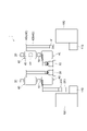
- FIG. 2 is a front view of a part of the transport system.
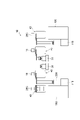
- FIG. 3 is a diagram showing a configuration of a control device.
- FIG. 4 is a front view of a part of the transport system according to another embodiment.
- FIG. 5 is a plan view of the transport system according to another embodiment.
- FIG. 6 is a front view of a part of the transport system shown in FIG.
- the transport system 1 is a system for transporting the FOUP (to be transported) 200.
- the transport system 1 includes a first track 10, a second track 20, a storage shelf (storage unit) 30, a ceiling transport vehicle (first ceiling transport vehicle, a second ceiling transport vehicle) 40 (see FIG. 2). It includes a control device 50 (see FIG. 3), a first power feeding device 60, and a second power feeding device 70 (see FIG. 3).
- the transport system 1 is installed in, for example, a semiconductor manufacturing factory equipped with a plurality of semiconductor processing devices 100.
- the FOUP 200 is transferred to the device port (transfer destination) 110 of the semiconductor processing device 100 by the ceiling transfer vehicle 40.
- the first track 10 is a member for traveling the ceiling carrier 40 and is suspended from the ceiling.
- the transport system 1 constitutes a plurality of systems (bays).
- the transport system 1 includes a plurality of intra-bay routes, which are travel paths in the bay, and an inter-bay route, which is a travel path connecting different bays. Intrabay routes are arranged along a plurality of device ports 110.
- the first orbit 10 includes an intrabay orbit 11 arranged in a plurality of intrabay routes and an interbay orbit 12 arranged in the interbay route.
- the intrabay track 11 is set so that the ceiling carrier 40 travels one way clockwise.
- the inter-bay track 12 is also set so that the ceiling carrier 40 travels clockwise in one way.
- the ceiling carrier 40 may be set to one-way counterclockwise.
- the second track 20 is a member for traveling the ceiling carrier 40 and is suspended from the ceiling.
- the second orbit 20 includes an intrabay orbit 21 arranged in a part of a plurality of intrabay routes and an interbay orbit 22 arranged in the interbay route.
- the intrabay track 21 is set so that the ceiling carrier 40 travels one way clockwise.
- the inter-bay track 22 is also set so that the ceiling carrier 40 travels clockwise in one way.
- the ceiling carrier 40 may be set to one-way counterclockwise.
- the first orbit 10 and the second orbit 20 are arranged side by side in the vertical (vertical) direction.
- the first orbit 10 is located below the second orbit 20.
- the second orbit 20 is located above the first orbit 10.
- the first orbit 10 is shown by a broken line
- the second orbit 20 is shown by a solid line.
- a plurality of device ports 110 are arranged outside the intrabay route along the direction in which the first track 10 and the second track 20 extend.
- the plurality of device ports 110 are provided so as to be located on one side and below of the first track 10 and the second track 20 arranged side by side.
- the FOUP 200 transferred from the ceiling carrier 40 is placed on the plurality of device ports 110, and the FOUP 200 is transferred to the semiconductor processing device 100. Further, in the plurality of device ports 110, when the semiconductor wafer housed in the FOUP 200 is processed by the semiconductor processing device 100, the FOUP 200 is transferred from the semiconductor processing device 100, and the FOUP 200 is placed on the FOUP 200. Become.
- the FOUP200 is placed on the storage shelf 30.
- the plurality of storage shelves 30 support the FOUP 200.
- the storage shelf 30 is suspended from the ceiling, for example.
- the storage shelf 30 may be an OWB (Overhead Buffer).
- the area on the storage shelf 30 on which the FOUP 200 can be placed can be placed.
- the area of the storage shelf 30 is a temporary storage area to which the ceiling carrier 40 stopped in the first track 10 and the second track 20 can transfer the FOUP 200.
- the plurality of storage shelves 30 are provided on the side and the lower side of one of the plurality of device ports 110 provided for the first track 10 and the second track 20. ing. That is, the plurality of storage shelves 30 are provided on the side facing the plurality of device ports 110 via the first track 10 and the second track 20 when viewed from the vertical direction.
- the storage shelf 30 is provided inside the loop-shaped intra-beirut.
- the ceiling carrier 40 includes, for example, a ceiling-suspended crane, OHT (Overhead Hoist Transfer), and the like.
- the FOUP 200 is a container (FOUP: Front Opening Unified Pod) for storing a semiconductor wafer.
- the ceiling carrier 40 has a grip portion 41, an elevating mechanism 42, and a moving mechanism 43.
- the ceiling carrier 40 has a transmission / reception unit 44 capable of communicating with the control device 50.
- the grip portion 41 is a device for gripping and releasing the FOUP 200.
- the grip portion 41 can grip the flange portion 210 of the FOUP 200.
- the grip portion 41 grips the flange portion 210 of the FOUP 200 when the ceiling carrier 40 acquires the FOUP 200 from the device port 110 and the storage shelf 30.
- the grip portion 41 releases the flange portion 210 of the FOUP 200 when the ceiling carrier 40 mounts the FOUP 200 on the device port 110 and the storage shelf 30.
- the elevating mechanism 42 is a device that elevates and elevates the grip portion 41 in the vertical direction.
- the elevating mechanism 42 can elevate the grip portion 41 in the vertical direction.
- the elevating mechanism 42 has a hoisting mechanism 42a and a belt 42b.
- the hoisting mechanism 42a is held by the moving mechanism 43.
- the hoisting mechanism 42a is a device for hoisting and unwinding the belt 42b in the vertical direction.
- the hoisting mechanism 42a can wind up and down the belt 42b in the vertical direction.
- the belt 42b is hung from the hoisting mechanism 42a and holds the grip portion 41 at the lower end thereof.
- the elevating mechanism 42 can be hoisted and unwound at a distance such that the FOUP 200 gripped by the grip 41 reaches at least the device port 110 and the storage shelf 30.
- the moving mechanism 43 is a device that moves the grip portion 41 and the elevating mechanism 42 from the ceiling carrier 40 to both sides. That is, the moving mechanism 43 can move the grip portion 41 and the elevating mechanism 42 from the ceiling carrier 40 in the horizontal direction perpendicular to the traveling direction of the ceiling carrier 40. The moving mechanism 43 can move the grip portion 41 and the elevating mechanism 42 above the device port 110 and the storage shelf 30, respectively. When the FOUP 200 is gripped by the grip portion 41, the moving mechanism 43 can move the FOUP 200 vertically upward of the device port 110 and the storage shelf 30.
- the ceiling carrier 40 stopped at the same position in the traveling direction in each of the first track 10 and the second track 20 has the device port 110 located laterally and below the first track 10 and the second track 20.
- the FOUP 200 can be transferred to both of the storage shelves 30.
- the ceiling carrier 40 can transfer the FOUP 200 to the same device port 110 and the same storage shelf 30. That is, both the ceiling carrier 40 on the first track 10 and the ceiling carrier 40 on the second track 20 can transfer (transfer) the FOUP 200 to and from the device port 110.
- both the ceiling carrier 40 on the first track 10 and the ceiling carrier 40 on the second track 20 can deliver the FOUP 200 to and from the storage shelf 30.
- the moving mechanism 43 is operated from the state where the grip portion 41 grips the flange portion 210 of the FOUP 200 directly under the first track 10 and the second track 20, and the FOUP 200 is set to the device port 110 and the storage shelf. Move above each of the thirty. Subsequently, the ceiling carrier 40 operates the hoisting mechanism 42a to wind down the belt 42b, lowers the FOUP 200, and places it on the device port 110 or the storage shelf 30. As described above, the ceiling carrier 40 transfers (places) the FOUP 200 to the device port 110 and the storage shelf 30.
- the ceiling carrier 40 grips the flange portion 210 of the FOUP 200 in a state of being placed on the device port 110 or the storage shelf 30 by the grip portion 41. Subsequently, the ceiling carrier 40 operates the hoisting mechanism 42a to wind up the belt 42b and raise the FOUP 200. Subsequently, the ceiling carrier 40 operates the moving mechanism 43 to move the FOUP 200 directly under the first track 10 and the second track 20. As described above, the ceiling carrier 40 transfers (acquires) the FOUP 200 from the device port 110 or the storage shelf 30.
- the transmission / reception unit 44 is arranged at a predetermined position of the ceiling carrier 40.
- the transmission / reception unit 44 of the ceiling carrier 40 traveling on the first track 10 can communicate with the first communication unit 55a or the second communication unit 55b (described later) of the control device 50.
- the transmission / reception unit 44 and the first communication unit 55a or the second communication unit 55b communicate with each other via, for example, a feeder line (not shown) laid along the first track 10.
- the transmission / reception unit 44 of the ceiling carrier 40 traveling on the second track 20 can communicate with the first communication unit 56a or the second communication unit 56b (described later).
- the ceiling carrier 40 transports the FOUP 200 based on the command received by the transmission / reception unit 44.
- the control device 50 includes a HOST 51, an MCS (Material Control System) 52, a first control unit 53, and a second control unit 54.
- the HOST 51, MCS 52, first control unit 53, and second control unit 54 are electronic control units composed of a CPU (Central Processing Unit), a ROM (Read Only Memory), a RAM (Random Access Memory), and the like.
- the first control unit 53 and the second control unit 54 operate independently of each other. As a result, even if one of the first control unit 53 and the second control unit 54 becomes inoperable, the other of the first control unit 53 and the second control unit 54 can operate.
- HOST 51 is a host controller.
- HOST 51 can be a MES (Manufacturing Execution System).
- the HOST 51 outputs a transport command and a travel command (hereinafter, simply referred to as “command”) to the MCS 52.
- command a travel command
- the MCS 52 acquires a command from the HOST 51, the MCS 52 outputs the command to the first control unit 53 or the second control unit 54 at a predetermined timing.
- the first control unit 53 controls the operation of the ceiling carrier 40 traveling on the first track 10.
- the first control unit 53 includes a first main controller 53a, a second main controller 53b, a first controller 53c, a second controller 53d, and a first communication device 55.
- the first main controller 53a and the second main controller 53b are MOHVC (Master Overhead Vehicle Controller).
- the first main controller 53a and the second main controller 53b transmit the command received from the MCS 52 to the first controller 53c or the second controller 53d.
- the first main controller 53a and the second main controller 53b have the same configuration.
- the first main controller 53a and the second main controller 53b do not perform control at the same time.
- the second main controller 53b operates when the first main controller 53a becomes inoperable.
- the first main controller 53a and the second main controller 53b may simultaneously perform control by sharing and processing a plurality of commands.
- the first controller 53c and the second controller 53d are OHVC (Overhead Hoist Vehicle Controller).
- the first controller 53c and the second controller 53d output a command received from the first main controller 53a or the second main controller 53b to the first communication device 55 (first communication unit 55a, second communication unit 55b).
- the first controller 53c and the second controller 53d have the same configuration.
- the first controller 53c and the second controller 53d do not perform control at the same time.
- the second controller 53d operates when the first controller 53c becomes inoperable.
- the first controller 53c and the second controller 53d may simultaneously perform control by sharing and processing a plurality of commands.
- the first communication device 55 has a first communication unit 55a and a second communication unit 55b.
- the first communication unit 55a and the second communication unit 55b communicate with the ceiling carrier 40 traveling on the first track 10.
- the first communication unit 55a and the second communication unit 55b transmit a command to the ceiling carrier 40.
- the first communication unit 55a and the second communication unit 55b have the same configuration.
- the first communication unit 55a and the second communication unit 55b do not operate at the same time.
- the second communication unit 55b operates when the first communication unit 55a becomes inoperable.
- Each of the first controller 53c and the second controller 53d can control each of the first communication unit 55a and the second communication unit 55b.
- the second control unit 54 controls the operation of the ceiling carrier 40 traveling on the second track 20.
- the second control unit 54 includes a first main controller 54a, a second main controller 54b, a first controller 54c, a second controller 54d, and a second communication device 56.
- the first main controller 54a and the second main controller 54b are MOHVC.
- the first main controller 54a and the second main controller 54b transmit the command received from the MCS 52 to the first controller 54c or the second controller 54d.
- it also has a role of allocating commands to an appropriate first controller 54c or second controller 54d.
- the first main controller 54a and the second main controller 54b have the same configuration.
- the first main controller 54a and the second main controller 54b do not perform control at the same time.
- the second main controller 54b operates when the first main controller 54a becomes inoperable.
- the first main controller 54a and the second main controller 54b may simultaneously perform control by sharing and processing a plurality of commands.
- the first controller 54c and the second controller 54d are OHVCs.
- the first controller 54c and the second controller 54d output a command received from the first main controller 54a or the second main controller 54b to the second communication device 56 (first communication unit 56a, second communication unit 56b).
- the first controller 54c and the second controller 54d have the same configuration.
- the first controller 54c and the second controller 54d do not perform control at the same time.
- the second controller 54d operates when the first controller 54c becomes inoperable.
- the first controller 54c and the second controller 54d may simultaneously perform control by sharing and processing a plurality of commands.
- the second communication device 56 has a first communication unit 56a and a second communication unit 56b.
- the first communication unit 56a and the second communication unit 56b communicate with the ceiling carrier 40 traveling on the second track 20.
- the first communication unit 56a and the second communication unit 56b transmit a command to the ceiling carrier 40.
- the first communication unit 56a and the second communication unit 56b have the same configuration.
- the first communication unit 56a and the second communication unit 56b do not operate at the same time.
- the second communication unit 56b operates when the first communication unit 56a becomes inoperable.
- Each of the first controller 54c and the second controller 54d can control each of the first communication unit 56a and the second communication unit 56b.
- the first power feeding device 60 supplies electric power to the ceiling carrier 40 traveling on the first track 10.
- the first feeding device 60 supplies electric power to a plurality of feeding lines (not shown) provided along the first track 10.
- the first power feeding device 60 includes a first power feeding board 61 and a second power feeding board 62.
- the first power supply board 61 and the second power supply board 62 can supply electric power independently of each other.
- the first power supply board 61 and the second power supply board 62 have the same configuration.
- the first power supply board 61 and the second power supply board 62 do not operate at the same time.
- the second power supply board 62 operates when the first power supply board 61 becomes inoperable.
- the second power feeding device 70 supplies electric power to the ceiling carrier 40 traveling on the second track 20.
- the second feeding device 70 supplies electric power to a plurality of feeding lines (not shown) provided along the second track 20.
- the second power feeding device 70 has a first power feeding board 71 and a second power feeding board 72.
- the first power supply board 71 and the second power supply board 72 can supply electric power independently of each other.
- the first power supply board 71 and the second power supply board 72 have the same configuration.
- the first power supply board 71 and the second power supply board 72 do not operate at the same time.
- the second power supply board 72 operates when the first power supply board 71 becomes inoperable.
- the ceiling transport vehicle 40 traveling on the first track 10 and the ceiling transport vehicle 40 traveling on the second track 20 each have the same device port 110.
- FOUP200 can be reprinted. Therefore, in the transport system 1, the transport efficiency of the FOUP 200 can be improved.
- the control device 50 controls the operation of the first control unit 53 that controls the operation of the ceiling transport vehicle 40 traveling on the first track 10 and the operation of the ceiling transport vehicle 40 traveling on the second track 20. In a situation where one of the first control unit 53 and the second control unit 54 is inoperable, the other of the first control unit 53 and the second control unit 54 can operate. ..
- the second control unit 54 causes the second track.
- the operation of the ceiling carrier 40 traveling on 20 can be continued. Therefore, in the transport system 1, the transfer of the FOUP 200 to the device port 110 can be continued. As a result, in the transport system 1, it is possible to avoid stopping the transfer of the FOUP 200 to the device port 110.
- the transport system 1 includes a storage shelf 30 for temporarily storing the FOUP 200.
- Each of the ceiling carrier 40 traveling on the first track 10 and the ceiling carrier 40 traveling on the second track 20 can transfer the FOUP 200 to the storage shelf 30.
- one of the ceiling carrier 40 of the first track 10 and the ceiling carrier 40 of the second track 20 places the FOUP 200 on the storage shelf 30, and the other ceiling carrier has the storage shelf. It is possible to perform an operation such as acquiring from 30 and mounting it on the device port 110. Therefore, in the transport system 1, the transport efficiency of the FOUP 200 can be further improved.
- the transport system 1 is for the first power feeding device 60 that supplies electric power to the ceiling transport vehicle 40 traveling on the first track 10 and the ceiling transport vehicle 40 traveling on the second track 20.
- a second power feeding device 70 for supplying electric power is provided.
- the other of the first feeding device 60 and the second feeding device 70 is operable.
- the second feeding device 70 travels on the second track 20. The operation of the ceiling carrier 40 can be continued.
- the first power supply device 60 has a first power supply board 61 and a second power supply board 62
- the second power supply device 70 has a first power supply board 71 and a second power supply board. It has a board 72.
- the first feeding boards 61 and 71 cannot operate, the second feeding boards 62 and 72 can operate.
- the ceiling carrier 40 from the second power supply boards 62, 72. Since the electric power is supplied to the ceiling carrier 40, the operation of the ceiling carrier 40 can be continued.
- the first control unit 53 includes a first communication device 55 that transmits a command to the ceiling transport vehicle 40 traveling on the first track 10.
- the second control unit 54 includes a second communication device 56 that transmits a command to the ceiling carrier 40 traveling on the second track 20.
- the other of the first communication device 55 and the second communication device 56 is operable. In this configuration, for example, even if some trouble occurs in the first communication device 55 and the operation of the ceiling carrier 40 traveling on the first track 10 is stopped, the second communication device 56 travels on the second track 20. The operation of the ceiling carrier 40 can be continued.
- the first communication device 55 has a first communication unit 55a and a second communication unit 55b
- the second communication device 56 has a first communication unit 56a and a second communication unit 56b. have.
- the second communication units 55b and 56b can operate.
- the ceiling transfer is performed from the second communication units 55b, 56b. Since the command is transmitted to the vehicle 40, the operation of the ceiling carrier 40 can be continued.
- the first control unit 53 has the first controller 53c and the second controller 53d
- the second control unit 54 has the first controller 54c and the second controller 54d.
- Each of the first controller 53c, 54c and the second controller 53d, 54d can control the first communication unit 55a, 56a and the second communication unit 55b, 56b, respectively.
- the second controllers 53d and 54d are the first communication units. Since the 55a, 56a or the second communication units 55b, 56b can be controlled (commands can be output to the first communication unit 55a, 56a or the second communication units 55b, 56b), the operation of the ceiling carrier 40 Can be continued.
- the transport system 1 includes a plurality of intrabay routes along a plurality of device ports 110 and an interbay route connecting the plurality of intrabay routes.
- the first orbit 10 includes an intrabay orbit 11 arranged in a plurality of intrabay routes and an interbay orbit 12 arranged in the interbay route.
- the second orbit 20 includes an intrabay orbit 21 arranged as a part of a plurality of intrabay routes.
- the intra-bay route with a large amount of transportation and the important intra-bay where system down is not allowed are made redundant to avoid the transfer stop of the transported object, and the other intra-bays are not made redundant. Therefore, in the transport system 1, it is possible to suppress the cost required for the track while making the important points redundant.
- each of the first track 10 and the second track 20 is arranged in the entire interbay route. In this configuration, it is possible to prevent the system from going down in the interbay route connecting the intrabay routes.
- the first track 10 and the second track 20 are arranged side by side in the vertical direction. With this configuration, it is possible to save space in the left-right direction.
- the embodiment in which the transport system 1 includes the first track 10 and the second track 20 has been described as an example.
- three or more orbits may be provided.
- three or more orbitals may be arranged side by side in the vertical direction.
- the second orbit 20 includes an intrabay orbit 21 arranged in a part of a plurality of intrabay routes has been described as an example.
- the second orbit 20 may be located on all intra-bay routes. In this configuration, it is possible to avoid the suspension of transfer of the FOUP 200 to the device port 110 in all the intravertices.
- first track 10 and the second track 20 are arranged at the same position in the vertical direction.
- first orbit 10 and the second orbit 20 may be arranged so as to be offset in the left-right direction in the vertical direction.
- the first control unit 53 includes the first main controller 53a, the second main controller 53b, the first controller 53c, and the second controller 53d has been described as an example.
- the first control unit 53 may further include a main controller and a controller. The same applies to the second control unit 54.
- the first communication device 55 has the first communication unit 55a and the second communication unit 55b has been described as an example.
- the first communication device 55 may further have a communication unit.
- the embodiment in which the first power supply device 60 has the first power supply board 61 and the second power supply board 62 has been described as an example.
- the first power feeding device 60 may further have a power feeding board.
- the two second tracks 20A and 20B may be arranged side by side in the left-right direction (horizontal direction).
- the second track 20A is arranged so that the device port 110 is located below.
- the second track 20B is arranged so that the storage shelf 30 is located below.
- the ceiling carrier 40 traveling on the second track 20A transfers the FOUP 200 to the device port 110
- the ceiling carrier 40 traveling on the second track 20B transfers the FOUP 200 to the storage shelf 30.
- the ceiling transport vehicle 40 traveling on the second tracks 20A and 20B can access each of the device port 110 and the storage shelf 30 at the same time, so that the transport efficiency can be further improved.
- the embodiment in which the first track 10 is located below the second track 20 has been described as an example.
- the first track 10 and the second track 20C may be arranged side by side in the left-right direction.
- the second orbital 20C has a loop shape.
- the second orbital 20C includes an intrabay orbital 21C arranged on an intrabay route straddling two adjacent semiconductor processing devices 100.
- the second track 20C and the first track 10 are connected via a branch track 15.
- the ceiling carrier 40 can enter the first track 10 (from the first track 10 to the second track 20) from the second track 20 without going through the interbay route.
- space can be saved in the vertical direction.
- the second track 20C does not have to be connected to the first track 10 or the interbay route via the branch track 15. That is, the second track 20C may be provided independently. Further, the second orbit 20 does not have to have a loop shape.
- the second track 20C may be linear along the arrangement direction of the semiconductor processing apparatus 100. In these configurations, the ceiling carrier 40 traveling on the second track 20C transfers (acquires) the FOUP 200 from the device port 110 of the semiconductor processing device 100 for which processing has been completed, and transports the FOUP 200 to a predetermined position.
- the object to be transported may be, for example, a container for storing a glass substrate, a reticle pod, a FOSB, a SMIF Pod, a general part, or the like.
- the transfer system 1 is installed in a semiconductor manufacturing factory.
- the transfer system is not limited to the semiconductor manufacturing factory, and can be applied to other facilities.
- 1,1A, 1B ... Transport system 10 ... 1st track, 20, 20A, 20B, 20C ... 2nd track, 30 ... Storage shelf (storage unit), 40 ... Ceiling carrier (1st ceiling carrier, 2nd) (Ceiling carrier), 50 ... control device, 53 ... first control unit, 54 ... second control unit, 55 ... first communication device, 55a ... first communication unit, 55b ... second communication unit, 56 ... second communication Device, 56a ... 1st communication unit, 56b ... 2nd communication unit, 60 ... 1st power supply device, 61 ... 1st power supply board, 62 ... 2nd power supply board, 70 ... 2nd power supply device, 71 ... 1st power supply board , 72 ... Second power supply board, 110 ... Device port (transfer destination), 200 ... FOUP (conveyed object).
Landscapes
- Engineering & Computer Science (AREA)
- Microelectronics & Electronic Packaging (AREA)
- Condensed Matter Physics & Semiconductors (AREA)
- General Physics & Mathematics (AREA)
- Manufacturing & Machinery (AREA)
- Computer Hardware Design (AREA)
- Physics & Mathematics (AREA)
- Power Engineering (AREA)
- Mechanical Engineering (AREA)
- Warehouses Or Storage Devices (AREA)
- Constituent Portions Of Griding Lathes, Driving, Sensing And Control (AREA)
- Adjustment And Processing Of Grains (AREA)
- Electrical Discharge Machining, Electrochemical Machining, And Combined Machining (AREA)
- Container, Conveyance, Adherence, Positioning, Of Wafer (AREA)
- Control Of Position, Course, Altitude, Or Attitude Of Moving Bodies (AREA)
Abstract
Description
Claims (12)
- 被搬送物を搬送すると共に前記被搬送物を移載する複数の天井搬送車と、
複数の前記天井搬送車のうち、第1天井搬送車が走行する第1軌道と、
複数の前記天井搬送車のうち、第2天井搬送車が走行し、且つ前記第1軌道に対して上下方向又は左右方向に並んで配置される第2軌道と、
複数の前記天井搬送車の動作を制御する制御装置と、を備え、
前記第1天井搬送車及び前記第2天井搬送車のそれぞれは、同一の移載先に対して前記被搬送物を移載可能であり、
前記制御装置は、前記第1天井搬送車の動作を制御する第1制御部と、前記第2天井搬送車の動作を制御する第2制御部と、を有し、
前記第1制御部及び前記第2制御部の一方が動作不能な状況において、前記第1制御部及び前記第2制御部の他方は動作可能である、搬送システム。 A plurality of ceiling transport vehicles that transport the transported object and transfer the transported object,
Of the plurality of ceiling transport vehicles, the first track on which the first ceiling transport vehicle travels and
Of the plurality of ceiling transport vehicles, a second track on which the second ceiling transport vehicle travels and is arranged side by side in the vertical direction or the horizontal direction with respect to the first track.
A control device for controlling the operation of the plurality of ceiling transport vehicles is provided.
Each of the first ceiling carrier and the second ceiling carrier can transfer the object to be transported to the same transfer destination.
The control device includes a first control unit that controls the operation of the first ceiling carrier and a second control unit that controls the operation of the second ceiling carrier.
A transport system in which one of the first control unit and the second control unit is inoperable, and the other of the first control unit and the second control unit is operable. - 前記被搬送物を一時的に保管する保管部を備え、
前記第1天井搬送車及び前記第2天井搬送車のそれぞれは、前記保管部に対して前記被搬送物を移載可能である、請求項1に記載の搬送システム。 A storage unit for temporarily storing the transported object is provided.
The transport system according to claim 1, wherein each of the first ceiling transport vehicle and the second ceiling transport vehicle can transfer the transported object to the storage unit. - 前記第1天井搬送車に対して電力を供給する第1給電装置、及び、前記第2天井搬送車に対して電力を供給する第2給電装置を備え、
前記第1給電装置及び前記第2給電装置の一方が動作不能な状況において、前記第1給電装置及び前記第2給電装置の他方は動作可能である、請求項1又は2に記載の搬送システム。 A first power supply device for supplying electric power to the first ceiling carrier and a second power supply device for supplying electric power to the second ceiling carrier are provided.
The transfer system according to claim 1 or 2, wherein when one of the first power feeding device and the second feeding device is inoperable, the other of the first feeding device and the second feeding device is operable. - 前記第1給電装置及び前記第2給電装置のそれぞれは、複数の給電盤を有し、
複数の前記給電盤のうちの一の前記給電盤が動作不能な状況において、他の前記給電盤は動作可能である、請求項3に記載の搬送システム。 Each of the first power feeding device and the second power feeding device has a plurality of power feeding boards.
The transfer system according to claim 3, wherein when one of the plurality of power supply boards is inoperable, the other power supply boards can be operated. - 前記第1制御部は、前記第1天井搬送車に搬送指令を送信する第1通信装置を備え、
前記第2制御部は、前記第2天井搬送車に搬送指令を送信する第2通信装置を備え、
前記第1通信装置及び前記第2通信装置の一方が動作不能な状況において、前記第1通信装置及び前記第2通信装置の他方は動作可能である、請求項1~4のいずれか一項に記載の搬送システム。 The first control unit includes a first communication device that transmits a transport command to the first ceiling transport vehicle.
The second control unit includes a second communication device that transmits a transport command to the second ceiling transport vehicle.
The first communication device and the other of the second communication devices are operable in a situation where one of the first communication device and the second communication device is inoperable, according to any one of claims 1 to 4. Described transport system. - 前記第1通信装置及び前記第2通信装置のそれぞれは、複数の通信部を有し、
複数の前記通信部のうちの一の前記通信部が動作不能な状況において、他の前記通信部は動作可能である、請求項5に記載の搬送システム。 Each of the first communication device and the second communication device has a plurality of communication units.
The transport system according to claim 5, wherein when the communication unit of one of the plurality of communication units is inoperable, the other communication units can operate. - 前記第1制御部及び前記第2制御部のそれぞれは、複数のコントローラを有し、
複数の前記コントローラのそれぞれは、複数の前記通信部のそれぞれを制御可能である、請求項6に記載の搬送システム。 Each of the first control unit and the second control unit has a plurality of controllers.
The transport system according to claim 6, wherein each of the plurality of controllers can control each of the plurality of communication units. - 複数の前記移載先に沿った複数のイントラベイルートと、複数の前記イントラベイルートを接続するインターベイルートと、を含み、
前記第1軌道は、前記複数の前記イントラベイルート及び前記インターベイルートに配置され、
前記第2軌道は、前記複数の前記イントラベイルートのうちの一部に配置されている、請求項1~7のいずれか一項に記載の搬送システム。 Includes a plurality of intrabay routes along the plurality of transfer destinations and an interbay route connecting the plurality of intrabay routes.
The first orbit is arranged in the plurality of the intra-beirut and the inter-bay route.
The transport system according to any one of claims 1 to 7, wherein the second track is arranged in a part of the plurality of intra-bay routes. - 前記第1軌道及び前記第2軌道のそれぞれは、前記インターベイルート全体に配置されている、請求項8に記載の搬送システム。 The transport system according to claim 8, wherein each of the first track and the second track is arranged in the entire interbay route.
- 前記第1軌道と前記第2軌道とは、上下方向において並んで配置されている、請求項1~9のいずれか一項に記載の搬送システム。 The transport system according to any one of claims 1 to 9, wherein the first track and the second track are arranged side by side in the vertical direction.
- 前記第1軌道と前記第2軌道とは、左右方向において並んで配置されている、請求項1~9のいずれか一項に記載の搬送システム。 The transport system according to any one of claims 1 to 9, wherein the first track and the second track are arranged side by side in the left-right direction.
- 前記第2軌道は、前記第1軌道よりも上方に2本配置されており、
2本の前記第2軌道は左右方向において並んで配置されており、
2本の前記第2軌道の一方は、下方に前記移載先が位置するように配置され、
2本の前記第2軌道の他方は、下方に前記保管部が位置するように配置されている、請求項2に記載の搬送システム。 Two of the second orbits are arranged above the first orbit.
The two second orbits are arranged side by side in the left-right direction.
One of the two second orbitals is arranged so that the transfer destination is located below.
The transfer system according to claim 2, wherein the other of the two second orbits is arranged so that the storage unit is located below.
Priority Applications (6)
| Application Number | Priority Date | Filing Date | Title |
|---|---|---|---|
| EP21903000.4A EP4261155A1 (en) | 2020-12-10 | 2021-10-13 | Conveyance system |
| IL303389A IL303389A (en) | 2020-12-10 | 2021-10-13 | Conveyance system |
| US18/256,374 US20240017931A1 (en) | 2020-12-10 | 2021-10-13 | Conveyance system |
| KR1020237022634A KR20230113806A (en) | 2020-12-10 | 2021-10-13 | conveying system |
| JP2022568076A JP7468703B2 (en) | 2020-12-10 | 2021-10-13 | Transport System |
| CN202180080818.7A CN116529864A (en) | 2020-12-10 | 2021-10-13 | Conveying system |
Applications Claiming Priority (2)
| Application Number | Priority Date | Filing Date | Title |
|---|---|---|---|
| JP2020-205051 | 2020-12-10 | ||
| JP2020205051 | 2020-12-10 |
Publications (1)
| Publication Number | Publication Date |
|---|---|
| WO2022123896A1 true WO2022123896A1 (en) | 2022-06-16 |
Family
ID=81973516
Family Applications (1)
| Application Number | Title | Priority Date | Filing Date |
|---|---|---|---|
| PCT/JP2021/037890 WO2022123896A1 (en) | 2020-12-10 | 2021-10-13 | Conveyance system |
Country Status (7)
| Country | Link |
|---|---|
| US (1) | US20240017931A1 (en) |
| EP (1) | EP4261155A1 (en) |
| JP (1) | JP7468703B2 (en) |
| KR (1) | KR20230113806A (en) |
| CN (1) | CN116529864A (en) |
| IL (1) | IL303389A (en) |
| WO (1) | WO2022123896A1 (en) |
Citations (6)
| Publication number | Priority date | Publication date | Assignee | Title |
|---|---|---|---|---|
| JPH0342577B2 (en) | 1983-11-08 | 1991-06-27 | ||
| JP2009009365A (en) * | 2007-06-28 | 2009-01-15 | Murata Mach Ltd | Carrier truck system |
| WO2014207977A1 (en) * | 2013-06-26 | 2014-12-31 | 村田機械株式会社 | Ceiling-traveling vehicle system, and wiring method for ceiling-traveling vehicle system |
| WO2017029871A1 (en) * | 2015-08-14 | 2017-02-23 | 村田機械株式会社 | Conveyance system |
| WO2017043234A1 (en) * | 2015-09-09 | 2017-03-16 | 村田機械株式会社 | Transport system and transport method |
| US20170194181A1 (en) * | 2016-01-04 | 2017-07-06 | Micron Technology, Inc. | Overhead traveling vehicle, transportation system with the same, and method of operating the same |
-
2021
- 2021-10-13 IL IL303389A patent/IL303389A/en unknown
- 2021-10-13 US US18/256,374 patent/US20240017931A1/en active Pending
- 2021-10-13 JP JP2022568076A patent/JP7468703B2/en active Active
- 2021-10-13 CN CN202180080818.7A patent/CN116529864A/en active Pending
- 2021-10-13 EP EP21903000.4A patent/EP4261155A1/en active Pending
- 2021-10-13 WO PCT/JP2021/037890 patent/WO2022123896A1/en active Application Filing
- 2021-10-13 KR KR1020237022634A patent/KR20230113806A/en not_active Application Discontinuation
Patent Citations (6)
| Publication number | Priority date | Publication date | Assignee | Title |
|---|---|---|---|---|
| JPH0342577B2 (en) | 1983-11-08 | 1991-06-27 | ||
| JP2009009365A (en) * | 2007-06-28 | 2009-01-15 | Murata Mach Ltd | Carrier truck system |
| WO2014207977A1 (en) * | 2013-06-26 | 2014-12-31 | 村田機械株式会社 | Ceiling-traveling vehicle system, and wiring method for ceiling-traveling vehicle system |
| WO2017029871A1 (en) * | 2015-08-14 | 2017-02-23 | 村田機械株式会社 | Conveyance system |
| WO2017043234A1 (en) * | 2015-09-09 | 2017-03-16 | 村田機械株式会社 | Transport system and transport method |
| US20170194181A1 (en) * | 2016-01-04 | 2017-07-06 | Micron Technology, Inc. | Overhead traveling vehicle, transportation system with the same, and method of operating the same |
Also Published As
| Publication number | Publication date |
|---|---|
| TW202227345A (en) | 2022-07-16 |
| US20240017931A1 (en) | 2024-01-18 |
| IL303389A (en) | 2023-08-01 |
| KR20230113806A (en) | 2023-08-01 |
| JP7468703B2 (en) | 2024-04-16 |
| JPWO2022123896A1 (en) | 2022-06-16 |
| CN116529864A (en) | 2023-08-01 |
| EP4261155A1 (en) | 2023-10-18 |
Similar Documents
| Publication | Publication Date | Title |
|---|---|---|
| KR101453828B1 (en) | Transfer system | |
| EP1707507B1 (en) | Overhead travelling vehicle system | |
| JP4337683B2 (en) | Transport system | |
| JP5880693B2 (en) | Transport system | |
| KR100965525B1 (en) | Modular terminal for high-throughput amhs | |
| JP6493538B2 (en) | Transport vehicle system | |
| US20100204826A1 (en) | Transfer apparatus | |
| JP2018070327A (en) | Article conveyance facility | |
| JP7211439B2 (en) | Conveyor system | |
| JPWO2007004551A1 (en) | Container transport device and container transport system | |
| JPWO2015064268A1 (en) | Conveyor equipment | |
| WO2022123896A1 (en) | Conveyance system | |
| WO2013150841A1 (en) | Conveyance system | |
| TWI858299B (en) | Transport system | |
| WO2022130758A1 (en) | Transport system | |
| WO2021220582A1 (en) | Overhead carrier and overhead carrying system | |
| JP7323059B2 (en) | carrier system | |
| JP3514312B2 (en) | Wafer transfer device | |
| KR20220126717A (en) | FOUP transfer device | |
| JP2009071120A (en) | Transfer method and transfer system | |
| WO2023188769A1 (en) | Conveyance system | |
| US12148643B2 (en) | Carrier vehicle system | |
| KR20240077309A (en) | apparatus and method for article transferring | |
| WO2024122138A1 (en) | Transport vehicle system | |
| KR20220060261A (en) | Interface apparatus and container transporting system with the apparatus |
Legal Events
| Date | Code | Title | Description |
|---|---|---|---|
| 121 | Ep: the epo has been informed by wipo that ep was designated in this application |
Ref document number: 21903000 Country of ref document: EP Kind code of ref document: A1 |
|
| ENP | Entry into the national phase |
Ref document number: 2022568076 Country of ref document: JP Kind code of ref document: A |
|
| WWE | Wipo information: entry into national phase |
Ref document number: 202180080818.7 Country of ref document: CN |
|
| WWE | Wipo information: entry into national phase |
Ref document number: 18256374 Country of ref document: US |
|
| ENP | Entry into the national phase |
Ref document number: 20237022634 Country of ref document: KR Kind code of ref document: A |
|
| NENP | Non-entry into the national phase |
Ref country code: DE |
|
| ENP | Entry into the national phase |
Ref document number: 2021903000 Country of ref document: EP Effective date: 20230710 |