EP3334653B1 - Pylon flugzeugtriebwerk mit integriertem multifunktionsrahmen - Google Patents
Pylon flugzeugtriebwerk mit integriertem multifunktionsrahmen Download PDFInfo
- Publication number
- EP3334653B1 EP3334653B1 EP16741025.7A EP16741025A EP3334653B1 EP 3334653 B1 EP3334653 B1 EP 3334653B1 EP 16741025 A EP16741025 A EP 16741025A EP 3334653 B1 EP3334653 B1 EP 3334653B1
- Authority
- EP
- European Patent Office
- Prior art keywords
- aircraft
- wing
- framework
- arms
- engine
- Prior art date
- Legal status (The legal status is an assumption and is not a legal conclusion. Google has not performed a legal analysis and makes no representation as to the accuracy of the status listed.)
- Not-in-force
Links
Images


Classifications
-
- B—PERFORMING OPERATIONS; TRANSPORTING
- B64—AIRCRAFT; AVIATION; COSMONAUTICS
- B64D—EQUIPMENT FOR FITTING IN OR TO AIRCRAFT; FLIGHT SUITS; PARACHUTES; ARRANGEMENT OR MOUNTING OF POWER PLANTS OR PROPULSION TRANSMISSIONS IN AIRCRAFT
- B64D27/00—Arrangement or mounting of power plants in aircraft; Aircraft characterised by the type or position of power plants
- B64D27/40—Arrangements for mounting power plants in aircraft
- B64D27/402—Arrangements for mounting power plants in aircraft comprising box like supporting frames, e.g. pylons or arrangements for embracing the power plant
Definitions
- the invention relates to an aircraft mast for rigidly attaching an engine to the wing or the fuselage of an aircraft, by suspension or attachment, this mast having an integrated multifunctional frame structure.
- the invention relates to the interface between an engine and the rest of an apparatus for any type of industrial product, in particular in the fields of aeronautics and space for which the optimization of the mass and production cycles constitute essential conditions.
- this link is a mast that connects all types of engines, in particular turbojets or turboprops.
- the figure 1 and its magnification at mast 1 and turbojet 3 ( Figure 1A ) illustrate the position of a conventional aircraft mast 1 between a wing 2 and the turbojet engine 3 of this aircraft 100.
- the mast 1 is equipped with a connection system to the wing 2 and the turbojet engine 3 by clashes. central and rear respectively at the rear level of the fan casing 3s and at the turbine casing 3t.
- a mast 1 is conventionally constituted by the assembly of several structures: a primary central rigid structure 4C, surrounded by secondary aerodynamic structures - a front structure 4A and a rear structure 4B - on either side of a fairing of 4K connection to the wing 2 (fairing said Karman, whose location is suggested in dotted lines), and a lower aerofoil fairing 4F disposed both under the primary structure 4C and under the rear aerodynamic structure 4B.
- the fastening hooks of the mast on the wing and on the casings of the turbojet engine namely respectively the fasteners 2c, 2r and 2m, 2n.
- the mechanical assembly of a mast consists of several hundred elements gathered in the basic structures, and intended to respond to mechanical stress or to convey fluids while trying to meet the objectives of mass and production cycle.
- Aircraft mast structures form a complex organ that is very constrained by the engine environment with multiple functions to be satisfied, in particular: aerodynamics, structuring, resumption of thrust forces, transmission of electrical wiring systems, supply of fuel, hydraulics and pneumatics between the engine and the wing by appropriate hoses.
- These structures usually consist of caissons formed by the assembly of upper and lower spars connected by lateral shroud panels reported and stiffened by transverse ribs. These boxes are designed to transmit to the wing the static and dynamic forces generated by the engines: mass, thrust, dynamic forces, vibrations.
- the patent document EP 2 426 051 plans to equip a central front attachment of a ball joint aligned transversely on the first orifices of the front lateral fasteners.
- the front attachment is flexible to absorb the deformations of the front fairing parts caused in particular by blade percussion of the blower.
- the patent document EP 2 030 892 proposes an articulation between two parts of the mast fixed to a crankcase of the engine and to the wing of airplane, which makes it possible to move the engine away from the wing in cruising phase and to bring them closer - and thus to distance the ground engine - in the take-off or landing phase.
- the document US 20120104162 discloses an aircraft mast having rigid attachment means to the engine and wing, with a channel for equipment and transmission systems and a separate frame.
- the document FR 2 931 133 discloses an aircraft mast with channels for equipment and transmission systems, these channels being on each side of a box of the mast.
- the document US 20110121132 shows another mast with a housingless frame for equipment and transmission systems between the engine and the wing.
- the air circuits installed in the masts include cold air intake pipes and hot air that converge inside the mast to a heat exchanger. These pipes are separate and attached to the structures. The temperature difference between these different pipes and the reception structure can be several hundred degrees Celsius. This results in differential expansion problems that can not be solved simply and effectively.
- the object of the invention is to overcome the problems raised by the state of the art, in particular those related to the complexity and the mass of the masts while satisfying the aerodynamic requirements, by a resolutely breaking approach to that of assembling an aircraft mast from dedicated caissons and to connect the assembly thus structured to the engine and to the wing by specific fasteners.
- the invention proposes in fact to organize the engine-wing interface around a substantially homogeneous framework, configured to integrate the multiple functions (via the circuit and pipe systems) and shelter the equipment of a mast (extinguishers, heat exchanger, etc.).
- This framework forms a structuring unit for transmitting the forces and forming an aerodynamic fairing adapted to this framework.
- the subject of the present invention is an aircraft mast intended to serve as an interface between an engine and an aircraft wing or fuselage by means of rigid attachment means to the engine and to the wing or fuselage of the aircraft.
- This mast has a unique structural and multifunctional framework, consisting of main channels accommodating equipment and transmission systems between the engine and the wing or the fuselage, and a mesh of arms and connecting links between the arms, these arms and / or these channels being able to fix fairing covers.
- the thus fixed covers then form an aerodynamic fairing in a predetermined conformation by a predetermined positioning of the arms and channels.
- circuits are an integral part of the frame, which eliminates installation problems, the use of fittings and therefore the associated risks of leakage.
- integration of cold and hot air circuits to the frame eliminates the possibilities of differential expansion because the frame consists of a single material.
- the qualifiers “upper” and “lower” refer to a configuration of engine suspension under the wing in standard use. In engine configuration above the wing, these qualifiers would of course be reversed. Furthermore, the terms “front”, “rear” and their equivalents are based on a standard use of the aircraft in its usual movement in flight. The qualifier “lateral” refers to a visualization along a plane parallel to the central plane of symmetry extending longitudinally in the axis of an aircraft.
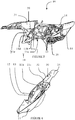
- FIG. 3 and 4 Illustrating an integrated frame mast Example 10 according to the invention achieved by the application of 3D technology in this example, appear the main channels 11, namely the channels 11a to 11c, connected by arms 12 forming a lattice link 20.
- the arms 12 connect the channels 11 to each other and intersect on nodes 13 for stiffening the entire frame 10.
- Non-structural covers 14 are fixed by removable means - bolts, clips, collars or equivalents - to the arms 12 of the lattice 20 and to the channels 11.
- Figures 3 and 4 part of the covers 14 is not shown to allow the display of the mast frame 10, the frame 10 being completely covered with covers 14 during its installation on an aircraft wing. And all the hoods form a fairing whose aerodynamics are controlled by the conformation that results from the relative positioning of the channels 11 and arms 12 of the mesh 20.
- walls 31 of the frame 10 form a thermally insulating housing 30 for a heat exchanger (not shown).
- thermal and / or electrical insulation walls - forming an integral part of the framework - may be provided between channels and truss arms to form dwellings, for example for a fire extinguisher or other equipment.
- a double-skinned channel 11a P1 and P2 accommodate circuits, for example hydraulic hoses or a fuel supply circuit (cf. figure 6 ).
- the channels 11d and 11e also accommodate air hoses for conditioning the cabin air.
- the side view of the figure 6 illustrates the hydraulic hoses 41a - advantageously configured as a homogeneous sheet -, the fuel circuit 41b and the extinguishing pipe 41c to be integrated respectively in the channels 11a, 11b, and 11c (cf. figures 4 and 5 ) of the mast frame 10 according to the invention. These channels are sized and configured to directly accommodate these circuits and pipes.
- the fuel circuit 41b is integrated in double skin in the channel 11b, the conformation of the sealed outer skin being controlled by the structural and aerodynamic resistance constraints of the frame 10 while respecting the inside diameters and the geometries as well as the interfaces on the wing side 2 and the engine side 3 (cf. figure 1 ).
- the dimensioning of the frame advantageously incorporates the over-constraints related to the thermal gradient between the wing and the engine.
- the material used to make the framework according to the invention may be a stainless steel containing nickel or an alloy mainly based on nickel and chromium, such as alloys "INCONEL" 625 or 718 also containing iron, molybdenum, niobium and cobalt.
- the mast can be attached, in equivalent embodiments, directly on a fuselage or on the wing of an aircraft.
- the frame can be made in one piece or in several pieces secured by welding, gluing or any other means of fixing such an assembly.
- the basic technology used is 3D printing and / or molding.
- fasteners on the wing and the engine of a frame mast according to the invention reproduce those used in the multi-box structure poles described with reference to FIGS. Figures 1A and 2 .
- the arm density in the lattice is substantially constant in the framework but may have a higher value in some parts of the mast, for example to form a rear lower fairing.
Landscapes
- Engineering & Computer Science (AREA)
- Aviation & Aerospace Engineering (AREA)
- Structures Of Non-Positive Displacement Pumps (AREA)
- Pressure Welding/Diffusion-Bonding (AREA)
- Connection Of Plates (AREA)
- Details Of Aerials (AREA)
Claims (6)
- Luftfahrzeug-Pylon, der dazu bestimmt ist, durch Einrichtungen zur starren Befestigung am Motor (2m, 2r) und an der Tragfläche (2c, 2r) oder am Rumpf des Luftfahrzeugs als Verbindungsstelle zwischen einem Motor (3) und einem Tragfläche (2) oder einem Luftfahrzeugrumpf zu dienen, dadurch gekennzeichnet, dass er ein einziges strukturierendes und multifunktionales Gerüst (10) aufweist, das von Hauptkanälen (11; 11a bis 11e), die Ausrüstungen und Übertragungssysteme (41a bis 41c) zwischen dem Motor (3) und dem Tragfläche (2) oder dem Rumpf aufnehmen, und einem Gitter (20) von Armen (12) und Verbindungsknoten (13) zwischen den Armen (12) gebildet wird, wobei diese Arme (12) und/oder Kanäle (11; 11a bis 11e) Verkleidungshauben (14) fixieren können, um durch eine vorab festgelegte Positionierung der Arme (12) und der Kanäle (11; 11a bis 11e) eine aerodynamische Verkleidung gemäß einer vorbestimmten Gestaltung zu formen.
- Luftfahrzeug-Pylon nach Anspruch 1, wobei das Gerüst (10) aus einer Metalllegierung ist, die ausgewählt wird aus einem nichtrostenden Stahl, der mindestens 10% Nickel enthält, und einer Legierung hauptsächlich auf der Basis von Nickel und Chrom.
- Luftfahrzeug-Pylon nach einem der Ansprüche 1 oder 2, wobei das Gerüst (10) durch eine Technik hergestellt wird, die aus dem Schweißen, dem Formen und/oder dem 3D-Druck ausgewählt wird.
- Luftfahrzeug-Pylon nach dem vorhergehenden Anspruch, wobei das Gerüst (10) entweder aus einem Stück, durch Anwenden einer Technik des Formens oder des 3D-Drucks, oder aus mehreren Bauteilen hergestellt wird, die durch Formen und/oder 3D-Druck hergestellt und miteinander verschweißt und/oder verklebt werden.
- Luftfahrzeug-Pylon nach einem der vorhergehenden Ansprüche, wobei mindestens eines der Übertragungssysteme (41a) gemäß einer Doppelhaut-Struktur (P1, P2) in die Kanäle (11a) eingebaut wird.
- Luftfahrzeug-Pylon nach einem der vorhergehenden Ansprüche, wobei die Hauben (14) durch ausbaubare mechanische Einrichtungen an den Armen (12) und/oder Kanälen (11; 11a bis 11e) des Gerüsts (10) fixiert werden.
Applications Claiming Priority (2)
| Application Number | Priority Date | Filing Date | Title |
|---|---|---|---|
| FR1557700A FR3040043B1 (fr) | 2015-08-12 | 2015-08-12 | Mat de moteur d'aeronef a ossature multifonctionnelle integree |
| PCT/EP2016/067266 WO2017025288A1 (fr) | 2015-08-12 | 2016-07-20 | Mât de moteur d'aéronef à ossature multifonctionnelle intégrée |
Publications (2)
| Publication Number | Publication Date |
|---|---|
| EP3334653A1 EP3334653A1 (de) | 2018-06-20 |
| EP3334653B1 true EP3334653B1 (de) | 2019-06-19 |
Family
ID=54356547
Family Applications (1)
| Application Number | Title | Priority Date | Filing Date |
|---|---|---|---|
| EP16741025.7A Not-in-force EP3334653B1 (de) | 2015-08-12 | 2016-07-20 | Pylon flugzeugtriebwerk mit integriertem multifunktionsrahmen |
Country Status (7)
| Country | Link |
|---|---|
| US (1) | US20180222595A1 (de) |
| EP (1) | EP3334653B1 (de) |
| CN (1) | CN107922052A (de) |
| BR (1) | BR112018002091A2 (de) |
| CA (1) | CA2995134A1 (de) |
| FR (1) | FR3040043B1 (de) |
| WO (1) | WO2017025288A1 (de) |
Families Citing this family (4)
| Publication number | Priority date | Publication date | Assignee | Title |
|---|---|---|---|---|
| FR3061148B1 (fr) * | 2016-12-23 | 2022-08-12 | Airbus Operations Sas | Fixation semi-continue d'un mat d'accrochage de moteur a un dispositif de fixation appartenant a la voilure d'un aeronef |
| CN109592050A (zh) * | 2018-11-02 | 2019-04-09 | 中国航空工业集团公司西安飞机设计研究所 | 一种飞机发动机吊挂结构 |
| CN109703773A (zh) * | 2018-12-28 | 2019-05-03 | 西北工业大学 | 一种自对正无人机火箭推力传递结构 |
| CN112644718B (zh) * | 2020-12-29 | 2023-05-23 | 中国航空工业集团公司西安飞机设计研究所 | 一种无人机的发动机吊挂结构 |
Family Cites Families (25)
| Publication number | Priority date | Publication date | Assignee | Title |
|---|---|---|---|---|
| US5123242A (en) * | 1990-07-30 | 1992-06-23 | General Electric Company | Precooling heat exchange arrangement integral with mounting structure fairing of gas turbine engine |
| US6838955B1 (en) | 1996-08-23 | 2005-01-04 | Hub Technologies, Inc. | Data processing device |
| FR2867157B1 (fr) | 2004-03-04 | 2006-06-02 | Airbus France | Systeme de montage interpose entre un moteur d'aeronef et une structure rigide d'un mat d'accrochage fixe sous une voilure de cet aeronef. |
| FR2867156B1 (fr) | 2004-03-04 | 2006-06-02 | Airbus France | Systeme de montage interpose entre un moteur d'aeronef et une structure rigide d'un mat d'accrochage fixe sous une voilure de cet aeronef. |
| FR2867158B1 (fr) | 2004-03-04 | 2007-06-08 | Airbus France | Systeme de montage interpose entre un moteur d'aeronef et une structure rigide d'un mat d'accrochage fixe sous une voilure de cet aeronef. |
| US7104306B2 (en) * | 2004-06-14 | 2006-09-12 | The Boeing Company | Cast unitized primary truss structure and method |
| FR2873988B1 (fr) * | 2004-08-05 | 2007-12-21 | Airbus France Sas | Mat d'accrochage de turboreacteur pour aeronef |
| FR2891243B1 (fr) * | 2005-09-26 | 2009-04-03 | Airbus France Sas | Mat d'accrochage de moteur pour aeronef |
| FR2891252B1 (fr) * | 2005-09-28 | 2007-10-26 | Airbus France Sas | Mat a ossature monolithique |
| FR2891248B1 (fr) * | 2005-09-28 | 2009-05-01 | Airbus France Sas | Ensemble moteur pour aeronef comprenant un moteur ainsi qu'un mat d'accrochage d'un tel moteur |
| CN100509561C (zh) * | 2006-05-30 | 2009-07-08 | 空中客车德国有限公司 | 带发动机的挂架的装配 |
| FR2902406B1 (fr) | 2006-06-20 | 2008-07-18 | Airbus France Sas | Carenage pour mat de suspension d'un turbomoteur a une aile d'aeronef |
| FR2920408B1 (fr) | 2007-08-30 | 2010-02-19 | Snecma | Pylone de suspension d'un moteur sous une aile d'avion |
| US8205825B2 (en) * | 2008-02-27 | 2012-06-26 | Spirit Aerosystems, Inc. | Engine pylon made from composite material |
| FR2931133B1 (fr) * | 2008-05-14 | 2010-06-18 | Airbus France | Mat d'accrochage de moteur comprenant des moyens de fixation des longerons et des panneaux agences en dehors de l'espace interieur de caisson |
| FR2935353B1 (fr) | 2008-09-03 | 2010-09-10 | Airbus France | Mat pour la suspension d'un turbomoteur sous une aile d'aeronef |
| FR2939103B1 (fr) * | 2008-12-01 | 2011-01-21 | Airbus France | Systeme hydraulique de transmission d'efforts entre un turbopropulseur d'aeronef et un dispositif d'accrochage |
| US7966921B1 (en) * | 2009-04-01 | 2011-06-28 | The United States Of America As Represented By The Secretary Of The Navy | Aircraft wing-pylon interface mounting apparatus |
| US8353476B2 (en) * | 2009-11-23 | 2013-01-15 | Spirit Aerosystems, Inc. | Truss-shaped engine pylon and method of making same |
| FR2964364B1 (fr) | 2010-09-03 | 2012-09-28 | Airbus Operations Sas | Mat d'accrochage de turboreacteur pour aeronef comprenant des attaches voilure avant alignees |
| FR2965548B1 (fr) | 2010-10-01 | 2012-10-19 | Airbus Operations Sas | Mat d'accrochage d'un moteur d'aeronef comprenant deux attaches voilure avant a pions de cisaillement orthogonaux |
| US9027875B2 (en) * | 2010-10-28 | 2015-05-12 | Spirit Aerosystems, Inc. | Pylon arrangement for open structure |
| US8661833B2 (en) * | 2011-01-14 | 2014-03-04 | Hamilton Sundstrand Corporation | Bleed valve module |
| US20140151497A1 (en) * | 2012-12-04 | 2014-06-05 | Ge Aviation Systems Llc | Engine pylon for an aircraft |
| JP6419437B2 (ja) * | 2014-02-28 | 2018-11-07 | 三菱航空機株式会社 | 航空機のエンジンパイロンおよび航空機 |
-
2015
- 2015-08-12 FR FR1557700A patent/FR3040043B1/fr not_active Expired - Fee Related
-
2016
- 2016-07-20 WO PCT/EP2016/067266 patent/WO2017025288A1/fr not_active Ceased
- 2016-07-20 EP EP16741025.7A patent/EP3334653B1/de not_active Not-in-force
- 2016-07-20 BR BR112018002091-5A patent/BR112018002091A2/pt not_active Application Discontinuation
- 2016-07-20 CN CN201680047499.9A patent/CN107922052A/zh active Pending
- 2016-07-20 US US15/750,527 patent/US20180222595A1/en not_active Abandoned
- 2016-07-20 CA CA2995134A patent/CA2995134A1/fr not_active Abandoned
Non-Patent Citations (1)
| Title |
|---|
| None * |
Also Published As
| Publication number | Publication date |
|---|---|
| WO2017025288A1 (fr) | 2017-02-16 |
| BR112018002091A2 (pt) | 2018-09-18 |
| FR3040043A1 (fr) | 2017-02-17 |
| US20180222595A1 (en) | 2018-08-09 |
| CN107922052A (zh) | 2018-04-17 |
| CA2995134A1 (fr) | 2017-02-16 |
| FR3040043B1 (fr) | 2019-04-12 |
| EP3334653A1 (de) | 2018-06-20 |
Similar Documents
| Publication | Publication Date | Title |
|---|---|---|
| EP3334653B1 (de) | Pylon flugzeugtriebwerk mit integriertem multifunktionsrahmen | |
| CN110259599B (zh) | 具有金属和复合构造的混合式内部固定结构 | |
| EP2895392B1 (de) | Metallische sandwichstruktur mit kleinem biegeradius | |
| US10246196B2 (en) | Aircraft engine assembly comprising at least two rear engine attachments axially shifted from each other | |
| US9889942B2 (en) | Aircraft assembly comprising a mounting pylon primary structure integrated to the structure of the wing element | |
| US8939398B2 (en) | Hinging cradle for fan cowls supported by said cowls in closed position | |
| US8800917B2 (en) | Aircraft engine pylon AFT aerodynamic fairing | |
| EP3546340B1 (de) | Hitzeschildanordnung und dessen montage an einem flugzeug | |
| EP3009649B1 (de) | Integrierter äusserer strömungswegkanal und vorderrahmensystem zur verwendung in einem mantelstrom-triebwerk und verfahren zur herstellung davon | |
| EP3552958B1 (de) | Optimiertes gondelprofil und optimierte kammerform für grenzschichtaufnahmeaktive laminare strömungssteuerung | |
| CA2890421A1 (en) | Aircraft propelling assembly including a duct forming a thermal barrier integrated in the caisson of the rigid structure of the engine mounting system | |
| US10562639B2 (en) | Aircraft engine assembly, comprising an attachment device for the engine equipped with a structural cover attached on a central box | |
| JP2017165394A (ja) | 性能強化型のジェットエンジン装着支柱 | |
| US9611758B2 (en) | Gas turbine engine systems involving integrated fluid conduits | |
| US10486822B2 (en) | Exhaust arrangement for aircraft having sensor | |
| Martin et al. | Understanding influence of powerplant component connection strategies on aircraft engine structural deformations | |
| JP2008545572A (ja) | 航空機用エンジンユニット | |
| FR3046134A1 (fr) | Hauban d'aeronef logeant un circuit de transfert de fluide | |
| CN108820246B (zh) | 一种小型涡喷发动机快速上机安装结构及方法 | |
| Kacik et al. | Review of the advantages and challenges of strut-braced and truss-braced aircraft | |
| Merlin | SR-71 BLACKBIRD. |
Legal Events
| Date | Code | Title | Description |
|---|---|---|---|
| STAA | Information on the status of an ep patent application or granted ep patent |
Free format text: STATUS: THE INTERNATIONAL PUBLICATION HAS BEEN MADE |
|
| PUAI | Public reference made under article 153(3) epc to a published international application that has entered the european phase |
Free format text: ORIGINAL CODE: 0009012 |
|
| STAA | Information on the status of an ep patent application or granted ep patent |
Free format text: STATUS: REQUEST FOR EXAMINATION WAS MADE |
|
| 17P | Request for examination filed |
Effective date: 20180312 |
|
| AK | Designated contracting states |
Kind code of ref document: A1 Designated state(s): AL AT BE BG CH CY CZ DE DK EE ES FI FR GB GR HR HU IE IS IT LI LT LU LV MC MK MT NL NO PL PT RO RS SE SI SK SM TR |
|
| AX | Request for extension of the european patent |
Extension state: BA ME |
|
| DAV | Request for validation of the european patent (deleted) | ||
| DAX | Request for extension of the european patent (deleted) | ||
| GRAP | Despatch of communication of intention to grant a patent |
Free format text: ORIGINAL CODE: EPIDOSNIGR1 |
|
| STAA | Information on the status of an ep patent application or granted ep patent |
Free format text: STATUS: GRANT OF PATENT IS INTENDED |
|
| INTG | Intention to grant announced |
Effective date: 20190114 |
|
| GRAS | Grant fee paid |
Free format text: ORIGINAL CODE: EPIDOSNIGR3 |
|
| GRAA | (expected) grant |
Free format text: ORIGINAL CODE: 0009210 |
|
| STAA | Information on the status of an ep patent application or granted ep patent |
Free format text: STATUS: THE PATENT HAS BEEN GRANTED |
|
| AK | Designated contracting states |
Kind code of ref document: B1 Designated state(s): AL AT BE BG CH CY CZ DE DK EE ES FI FR GB GR HR HU IE IS IT LI LT LU LV MC MK MT NL NO PL PT RO RS SE SI SK SM TR |
|
| REG | Reference to a national code |
Ref country code: GB Ref legal event code: FG4D Free format text: NOT ENGLISH |
|
| REG | Reference to a national code |
Ref country code: CH Ref legal event code: EP |
|
| REG | Reference to a national code |
Ref country code: IE Ref legal event code: FG4D Free format text: LANGUAGE OF EP DOCUMENT: FRENCH |
|
| REG | Reference to a national code |
Ref country code: DE Ref legal event code: R096 Ref document number: 602016015600 Country of ref document: DE |
|
| REG | Reference to a national code |
Ref country code: AT Ref legal event code: REF Ref document number: 1145203 Country of ref document: AT Kind code of ref document: T Effective date: 20190715 |
|
| REG | Reference to a national code |
Ref country code: NL Ref legal event code: MP Effective date: 20190619 |
|
| PG25 | Lapsed in a contracting state [announced via postgrant information from national office to epo] |
Ref country code: FI Free format text: LAPSE BECAUSE OF FAILURE TO SUBMIT A TRANSLATION OF THE DESCRIPTION OR TO PAY THE FEE WITHIN THE PRESCRIBED TIME-LIMIT Effective date: 20190619 Ref country code: NO Free format text: LAPSE BECAUSE OF FAILURE TO SUBMIT A TRANSLATION OF THE DESCRIPTION OR TO PAY THE FEE WITHIN THE PRESCRIBED TIME-LIMIT Effective date: 20190919 Ref country code: AL Free format text: LAPSE BECAUSE OF FAILURE TO SUBMIT A TRANSLATION OF THE DESCRIPTION OR TO PAY THE FEE WITHIN THE PRESCRIBED TIME-LIMIT Effective date: 20190619 Ref country code: HR Free format text: LAPSE BECAUSE OF FAILURE TO SUBMIT A TRANSLATION OF THE DESCRIPTION OR TO PAY THE FEE WITHIN THE PRESCRIBED TIME-LIMIT Effective date: 20190619 Ref country code: SE Free format text: LAPSE BECAUSE OF FAILURE TO SUBMIT A TRANSLATION OF THE DESCRIPTION OR TO PAY THE FEE WITHIN THE PRESCRIBED TIME-LIMIT Effective date: 20190619 Ref country code: LT Free format text: LAPSE BECAUSE OF FAILURE TO SUBMIT A TRANSLATION OF THE DESCRIPTION OR TO PAY THE FEE WITHIN THE PRESCRIBED TIME-LIMIT Effective date: 20190619 |
|
| PGFP | Annual fee paid to national office [announced via postgrant information from national office to epo] |
Ref country code: FR Payment date: 20190729 Year of fee payment: 4 Ref country code: DE Payment date: 20190913 Year of fee payment: 4 |
|
| REG | Reference to a national code |
Ref country code: LT Ref legal event code: MG4D |
|
| PG25 | Lapsed in a contracting state [announced via postgrant information from national office to epo] |
Ref country code: RS Free format text: LAPSE BECAUSE OF FAILURE TO SUBMIT A TRANSLATION OF THE DESCRIPTION OR TO PAY THE FEE WITHIN THE PRESCRIBED TIME-LIMIT Effective date: 20190619 Ref country code: GR Free format text: LAPSE BECAUSE OF FAILURE TO SUBMIT A TRANSLATION OF THE DESCRIPTION OR TO PAY THE FEE WITHIN THE PRESCRIBED TIME-LIMIT Effective date: 20190920 Ref country code: BG Free format text: LAPSE BECAUSE OF FAILURE TO SUBMIT A TRANSLATION OF THE DESCRIPTION OR TO PAY THE FEE WITHIN THE PRESCRIBED TIME-LIMIT Effective date: 20190919 Ref country code: LV Free format text: LAPSE BECAUSE OF FAILURE TO SUBMIT A TRANSLATION OF THE DESCRIPTION OR TO PAY THE FEE WITHIN THE PRESCRIBED TIME-LIMIT Effective date: 20190619 |
|
| REG | Reference to a national code |
Ref country code: AT Ref legal event code: MK05 Ref document number: 1145203 Country of ref document: AT Kind code of ref document: T Effective date: 20190619 |
|
| PG25 | Lapsed in a contracting state [announced via postgrant information from national office to epo] |
Ref country code: CZ Free format text: LAPSE BECAUSE OF FAILURE TO SUBMIT A TRANSLATION OF THE DESCRIPTION OR TO PAY THE FEE WITHIN THE PRESCRIBED TIME-LIMIT Effective date: 20190619 Ref country code: RO Free format text: LAPSE BECAUSE OF FAILURE TO SUBMIT A TRANSLATION OF THE DESCRIPTION OR TO PAY THE FEE WITHIN THE PRESCRIBED TIME-LIMIT Effective date: 20190619 Ref country code: AT Free format text: LAPSE BECAUSE OF FAILURE TO SUBMIT A TRANSLATION OF THE DESCRIPTION OR TO PAY THE FEE WITHIN THE PRESCRIBED TIME-LIMIT Effective date: 20190619 Ref country code: EE Free format text: LAPSE BECAUSE OF FAILURE TO SUBMIT A TRANSLATION OF THE DESCRIPTION OR TO PAY THE FEE WITHIN THE PRESCRIBED TIME-LIMIT Effective date: 20190619 Ref country code: PT Free format text: LAPSE BECAUSE OF FAILURE TO SUBMIT A TRANSLATION OF THE DESCRIPTION OR TO PAY THE FEE WITHIN THE PRESCRIBED TIME-LIMIT Effective date: 20191021 Ref country code: NL Free format text: LAPSE BECAUSE OF FAILURE TO SUBMIT A TRANSLATION OF THE DESCRIPTION OR TO PAY THE FEE WITHIN THE PRESCRIBED TIME-LIMIT Effective date: 20190619 Ref country code: SK Free format text: LAPSE BECAUSE OF FAILURE TO SUBMIT A TRANSLATION OF THE DESCRIPTION OR TO PAY THE FEE WITHIN THE PRESCRIBED TIME-LIMIT Effective date: 20190619 |
|
| PG25 | Lapsed in a contracting state [announced via postgrant information from national office to epo] |
Ref country code: IT Free format text: LAPSE BECAUSE OF FAILURE TO SUBMIT A TRANSLATION OF THE DESCRIPTION OR TO PAY THE FEE WITHIN THE PRESCRIBED TIME-LIMIT Effective date: 20190619 Ref country code: IS Free format text: LAPSE BECAUSE OF FAILURE TO SUBMIT A TRANSLATION OF THE DESCRIPTION OR TO PAY THE FEE WITHIN THE PRESCRIBED TIME-LIMIT Effective date: 20191019 Ref country code: SM Free format text: LAPSE BECAUSE OF FAILURE TO SUBMIT A TRANSLATION OF THE DESCRIPTION OR TO PAY THE FEE WITHIN THE PRESCRIBED TIME-LIMIT Effective date: 20190619 Ref country code: ES Free format text: LAPSE BECAUSE OF FAILURE TO SUBMIT A TRANSLATION OF THE DESCRIPTION OR TO PAY THE FEE WITHIN THE PRESCRIBED TIME-LIMIT Effective date: 20190619 |
|
| REG | Reference to a national code |
Ref country code: CH Ref legal event code: PL |
|
| PG25 | Lapsed in a contracting state [announced via postgrant information from national office to epo] |
Ref country code: TR Free format text: LAPSE BECAUSE OF FAILURE TO SUBMIT A TRANSLATION OF THE DESCRIPTION OR TO PAY THE FEE WITHIN THE PRESCRIBED TIME-LIMIT Effective date: 20190619 Ref country code: MC Free format text: LAPSE BECAUSE OF FAILURE TO SUBMIT A TRANSLATION OF THE DESCRIPTION OR TO PAY THE FEE WITHIN THE PRESCRIBED TIME-LIMIT Effective date: 20190619 |
|
| REG | Reference to a national code |
Ref country code: BE Ref legal event code: MM Effective date: 20190731 |
|
| PG25 | Lapsed in a contracting state [announced via postgrant information from national office to epo] |
Ref country code: DK Free format text: LAPSE BECAUSE OF FAILURE TO SUBMIT A TRANSLATION OF THE DESCRIPTION OR TO PAY THE FEE WITHIN THE PRESCRIBED TIME-LIMIT Effective date: 20190619 Ref country code: PL Free format text: LAPSE BECAUSE OF FAILURE TO SUBMIT A TRANSLATION OF THE DESCRIPTION OR TO PAY THE FEE WITHIN THE PRESCRIBED TIME-LIMIT Effective date: 20190619 |
|
| PG25 | Lapsed in a contracting state [announced via postgrant information from national office to epo] |
Ref country code: CH Free format text: LAPSE BECAUSE OF NON-PAYMENT OF DUE FEES Effective date: 20190731 Ref country code: LI Free format text: LAPSE BECAUSE OF NON-PAYMENT OF DUE FEES Effective date: 20190731 Ref country code: BE Free format text: LAPSE BECAUSE OF NON-PAYMENT OF DUE FEES Effective date: 20190731 Ref country code: IS Free format text: LAPSE BECAUSE OF FAILURE TO SUBMIT A TRANSLATION OF THE DESCRIPTION OR TO PAY THE FEE WITHIN THE PRESCRIBED TIME-LIMIT Effective date: 20200224 Ref country code: LU Free format text: LAPSE BECAUSE OF NON-PAYMENT OF DUE FEES Effective date: 20190720 |
|
| REG | Reference to a national code |
Ref country code: DE Ref legal event code: R097 Ref document number: 602016015600 Country of ref document: DE |
|
| PLBE | No opposition filed within time limit |
Free format text: ORIGINAL CODE: 0009261 |
|
| STAA | Information on the status of an ep patent application or granted ep patent |
Free format text: STATUS: NO OPPOSITION FILED WITHIN TIME LIMIT |
|
| PG2D | Information on lapse in contracting state deleted |
Ref country code: IS |
|
| PG25 | Lapsed in a contracting state [announced via postgrant information from national office to epo] |
Ref country code: IE Free format text: LAPSE BECAUSE OF NON-PAYMENT OF DUE FEES Effective date: 20190720 |
|
| 26N | No opposition filed |
Effective date: 20200603 |
|
| PG25 | Lapsed in a contracting state [announced via postgrant information from national office to epo] |
Ref country code: SI Free format text: LAPSE BECAUSE OF FAILURE TO SUBMIT A TRANSLATION OF THE DESCRIPTION OR TO PAY THE FEE WITHIN THE PRESCRIBED TIME-LIMIT Effective date: 20190619 |
|
| REG | Reference to a national code |
Ref country code: DE Ref legal event code: R119 Ref document number: 602016015600 Country of ref document: DE |
|
| GBPC | Gb: european patent ceased through non-payment of renewal fee |
Effective date: 20200720 |
|
| PG25 | Lapsed in a contracting state [announced via postgrant information from national office to epo] |
Ref country code: FR Free format text: LAPSE BECAUSE OF NON-PAYMENT OF DUE FEES Effective date: 20200731 Ref country code: GB Free format text: LAPSE BECAUSE OF NON-PAYMENT OF DUE FEES Effective date: 20200720 |
|
| PG25 | Lapsed in a contracting state [announced via postgrant information from national office to epo] |
Ref country code: CY Free format text: LAPSE BECAUSE OF FAILURE TO SUBMIT A TRANSLATION OF THE DESCRIPTION OR TO PAY THE FEE WITHIN THE PRESCRIBED TIME-LIMIT Effective date: 20190619 Ref country code: DE Free format text: LAPSE BECAUSE OF NON-PAYMENT OF DUE FEES Effective date: 20210202 |
|
| PG25 | Lapsed in a contracting state [announced via postgrant information from national office to epo] |
Ref country code: MT Free format text: LAPSE BECAUSE OF FAILURE TO SUBMIT A TRANSLATION OF THE DESCRIPTION OR TO PAY THE FEE WITHIN THE PRESCRIBED TIME-LIMIT Effective date: 20190619 Ref country code: HU Free format text: LAPSE BECAUSE OF FAILURE TO SUBMIT A TRANSLATION OF THE DESCRIPTION OR TO PAY THE FEE WITHIN THE PRESCRIBED TIME-LIMIT; INVALID AB INITIO Effective date: 20160720 |
|
| PG25 | Lapsed in a contracting state [announced via postgrant information from national office to epo] |
Ref country code: MK Free format text: LAPSE BECAUSE OF FAILURE TO SUBMIT A TRANSLATION OF THE DESCRIPTION OR TO PAY THE FEE WITHIN THE PRESCRIBED TIME-LIMIT Effective date: 20190619 |