EP3333604A1 - Mehrkernglasfaser und verfahren zur herstellung von mehrkernglasfaser - Google Patents
Mehrkernglasfaser und verfahren zur herstellung von mehrkernglasfaser Download PDFInfo
- Publication number
- EP3333604A1 EP3333604A1 EP16832825.0A EP16832825A EP3333604A1 EP 3333604 A1 EP3333604 A1 EP 3333604A1 EP 16832825 A EP16832825 A EP 16832825A EP 3333604 A1 EP3333604 A1 EP 3333604A1
- Authority
- EP
- European Patent Office
- Prior art keywords
- clad
- core
- optical fiber
- multicore optical
- refractive index
- Prior art date
- Legal status (The legal status is an assumption and is not a legal conclusion. Google has not performed a legal analysis and makes no representation as to the accuracy of the status listed.)
- Withdrawn
Links
- 239000013307 optical fiber Substances 0.000 title claims abstract description 120
- 238000004519 manufacturing process Methods 0.000 title description 5
- VYPSYNLAJGMNEJ-UHFFFAOYSA-N Silicium dioxide Chemical compound O=[Si]=O VYPSYNLAJGMNEJ-UHFFFAOYSA-N 0.000 claims abstract description 47
- 229910052731 fluorine Inorganic materials 0.000 claims abstract description 31
- 239000011737 fluorine Substances 0.000 claims abstract description 31
- 239000000377 silicon dioxide Substances 0.000 claims abstract description 6
- 230000005540 biological transmission Effects 0.000 claims description 32
- YCKRFDGAMUMZLT-UHFFFAOYSA-N Fluorine atom Chemical compound [F] YCKRFDGAMUMZLT-UHFFFAOYSA-N 0.000 claims description 29
- 230000005855 radiation Effects 0.000 claims description 29
- 229910052739 hydrogen Inorganic materials 0.000 claims description 14
- 239000001257 hydrogen Substances 0.000 claims description 14
- 238000000034 method Methods 0.000 claims description 13
- UFHFLCQGNIYNRP-UHFFFAOYSA-N Hydrogen Chemical compound [H][H] UFHFLCQGNIYNRP-UHFFFAOYSA-N 0.000 claims description 12
- 230000008018 melting Effects 0.000 claims description 7
- 238000002844 melting Methods 0.000 claims description 7
- PXGOKWXKJXAPGV-UHFFFAOYSA-N Fluorine Chemical compound FF PXGOKWXKJXAPGV-UHFFFAOYSA-N 0.000 abstract 2
- 230000000052 comparative effect Effects 0.000 description 13
- 239000010410 layer Substances 0.000 description 11
- 239000011521 glass Substances 0.000 description 10
- 230000007547 defect Effects 0.000 description 7
- 235000012239 silicon dioxide Nutrition 0.000 description 7
- 239000000835 fiber Substances 0.000 description 6
- OCKGFTQIICXDQW-ZEQRLZLVSA-N 5-[(1r)-1-hydroxy-2-[4-[(2r)-2-hydroxy-2-(4-methyl-1-oxo-3h-2-benzofuran-5-yl)ethyl]piperazin-1-yl]ethyl]-4-methyl-3h-2-benzofuran-1-one Chemical compound C1=C2C(=O)OCC2=C(C)C([C@@H](O)CN2CCN(CC2)C[C@H](O)C2=CC=C3C(=O)OCC3=C2C)=C1 OCKGFTQIICXDQW-ZEQRLZLVSA-N 0.000 description 4
- ZAMOUSCENKQFHK-UHFFFAOYSA-N Chlorine atom Chemical compound [Cl] ZAMOUSCENKQFHK-UHFFFAOYSA-N 0.000 description 4
- 229910052801 chlorine Inorganic materials 0.000 description 4
- 239000000460 chlorine Substances 0.000 description 4
- 239000011247 coating layer Substances 0.000 description 4
- -1 for example Chemical compound 0.000 description 4
- 238000009792 diffusion process Methods 0.000 description 3
- 239000002019 doping agent Substances 0.000 description 3
- 230000000694 effects Effects 0.000 description 3
- 239000000203 mixture Substances 0.000 description 3
- 238000005229 chemical vapour deposition Methods 0.000 description 2
- 150000001805 chlorine compounds Chemical class 0.000 description 2
- 238000009826 distribution Methods 0.000 description 2
- 238000002309 gasification Methods 0.000 description 2
- 150000002431 hydrogen Chemical class 0.000 description 2
- 239000000463 material Substances 0.000 description 2
- 238000012545 processing Methods 0.000 description 2
- 229920005989 resin Polymers 0.000 description 2
- 239000011347 resin Substances 0.000 description 2
- FYSNRJHAOHDILO-UHFFFAOYSA-N thionyl chloride Chemical compound ClS(Cl)=O FYSNRJHAOHDILO-UHFFFAOYSA-N 0.000 description 2
- ZOXJGFHDIHLPTG-UHFFFAOYSA-N Boron Chemical compound [B] ZOXJGFHDIHLPTG-UHFFFAOYSA-N 0.000 description 1
- 239000004593 Epoxy Substances 0.000 description 1
- 239000004642 Polyimide Substances 0.000 description 1
- 229910006124 SOCl2 Inorganic materials 0.000 description 1
- 229910003910 SiCl4 Inorganic materials 0.000 description 1
- 239000000654 additive Substances 0.000 description 1
- 230000000996 additive effect Effects 0.000 description 1
- 230000004888 barrier function Effects 0.000 description 1
- 229910052796 boron Inorganic materials 0.000 description 1
- JJWKPURADFRFRB-UHFFFAOYSA-N carbonyl sulfide Chemical compound O=C=S JJWKPURADFRFRB-UHFFFAOYSA-N 0.000 description 1
- 238000005520 cutting process Methods 0.000 description 1
- 230000018044 dehydration Effects 0.000 description 1
- 238000006297 dehydration reaction Methods 0.000 description 1
- 238000000151 deposition Methods 0.000 description 1
- 230000008021 deposition Effects 0.000 description 1
- 238000010586 diagram Methods 0.000 description 1
- 238000012681 fiber drawing Methods 0.000 description 1
- 238000005187 foaming Methods 0.000 description 1
- 238000007496 glass forming Methods 0.000 description 1
- 229910052736 halogen Inorganic materials 0.000 description 1
- 150000002367 halogens Chemical class 0.000 description 1
- 238000010438 heat treatment Methods 0.000 description 1
- 238000005286 illumination Methods 0.000 description 1
- 238000003475 lamination Methods 0.000 description 1
- 230000004048 modification Effects 0.000 description 1
- 238000012986 modification Methods 0.000 description 1
- 230000002093 peripheral effect Effects 0.000 description 1
- 229920001721 polyimide Polymers 0.000 description 1
- 229920001296 polysiloxane Polymers 0.000 description 1
- 238000012805 post-processing Methods 0.000 description 1
- 239000012857 radioactive material Substances 0.000 description 1
- 239000002994 raw material Substances 0.000 description 1
- FDNAPBUWERUEDA-UHFFFAOYSA-N silicon tetrachloride Chemical compound Cl[Si](Cl)(Cl)Cl FDNAPBUWERUEDA-UHFFFAOYSA-N 0.000 description 1
- 238000005245 sintering Methods 0.000 description 1
- 239000012808 vapor phase Substances 0.000 description 1
Images


Classifications
-
- G—PHYSICS
- G02—OPTICS
- G02B—OPTICAL ELEMENTS, SYSTEMS OR APPARATUS
- G02B6/00—Light guides; Structural details of arrangements comprising light guides and other optical elements, e.g. couplings
- G02B6/02—Optical fibres with cladding with or without a coating
- G02B6/02042—Multicore optical fibres
-
- C—CHEMISTRY; METALLURGY
- C03—GLASS; MINERAL OR SLAG WOOL
- C03B—MANUFACTURE, SHAPING, OR SUPPLEMENTARY PROCESSES
- C03B37/00—Manufacture or treatment of flakes, fibres, or filaments from softened glass, minerals, or slags
- C03B37/01—Manufacture of glass fibres or filaments
- C03B37/012—Manufacture of preforms for drawing fibres or filaments
- C03B37/01205—Manufacture of preforms for drawing fibres or filaments starting from tubes, rods, fibres or filaments
- C03B37/01211—Manufacture of preforms for drawing fibres or filaments starting from tubes, rods, fibres or filaments by inserting one or more rods or tubes into a tube
-
- C—CHEMISTRY; METALLURGY
- C03—GLASS; MINERAL OR SLAG WOOL
- C03B—MANUFACTURE, SHAPING, OR SUPPLEMENTARY PROCESSES
- C03B37/00—Manufacture or treatment of flakes, fibres, or filaments from softened glass, minerals, or slags
- C03B37/01—Manufacture of glass fibres or filaments
- C03B37/02—Manufacture of glass fibres or filaments by drawing or extruding, e.g. direct drawing of molten glass from nozzles; Cooling fins therefor
- C03B37/025—Manufacture of glass fibres or filaments by drawing or extruding, e.g. direct drawing of molten glass from nozzles; Cooling fins therefor from reheated softened tubes, rods, fibres or filaments, e.g. drawing fibres from preforms
- C03B37/028—Drawing fibre bundles, e.g. for making fibre bundles of multifibres, image fibres
-
- G—PHYSICS
- G02—OPTICS
- G02B—OPTICAL ELEMENTS, SYSTEMS OR APPARATUS
- G02B6/00—Light guides; Structural details of arrangements comprising light guides and other optical elements, e.g. couplings
- G02B6/02—Optical fibres with cladding with or without a coating
-
- G—PHYSICS
- G02—OPTICS
- G02B—OPTICAL ELEMENTS, SYSTEMS OR APPARATUS
- G02B6/00—Light guides; Structural details of arrangements comprising light guides and other optical elements, e.g. couplings
- G02B6/02—Optical fibres with cladding with or without a coating
- G02B6/036—Optical fibres with cladding with or without a coating core or cladding comprising multiple layers
-
- G—PHYSICS
- G02—OPTICS
- G02B—OPTICAL ELEMENTS, SYSTEMS OR APPARATUS
- G02B6/00—Light guides; Structural details of arrangements comprising light guides and other optical elements, e.g. couplings
- G02B6/02—Optical fibres with cladding with or without a coating
- G02B6/036—Optical fibres with cladding with or without a coating core or cladding comprising multiple layers
- G02B6/03616—Optical fibres characterised both by the number of different refractive index layers around the central core segment, i.e. around the innermost high index core layer, and their relative refractive index difference
- G02B6/03622—Optical fibres characterised both by the number of different refractive index layers around the central core segment, i.e. around the innermost high index core layer, and their relative refractive index difference having 2 layers only
- G02B6/03627—Optical fibres characterised both by the number of different refractive index layers around the central core segment, i.e. around the innermost high index core layer, and their relative refractive index difference having 2 layers only arranged - +
-
- G—PHYSICS
- G02—OPTICS
- G02B—OPTICAL ELEMENTS, SYSTEMS OR APPARATUS
- G02B6/00—Light guides; Structural details of arrangements comprising light guides and other optical elements, e.g. couplings
- G02B6/04—Light guides; Structural details of arrangements comprising light guides and other optical elements, e.g. couplings formed by bundles of fibres
-
- C—CHEMISTRY; METALLURGY
- C03—GLASS; MINERAL OR SLAG WOOL
- C03B—MANUFACTURE, SHAPING, OR SUPPLEMENTARY PROCESSES
- C03B2201/00—Type of glass produced
- C03B2201/06—Doped silica-based glasses
- C03B2201/08—Doped silica-based glasses doped with boron or fluorine or other refractive index decreasing dopant
-
- C—CHEMISTRY; METALLURGY
- C03—GLASS; MINERAL OR SLAG WOOL
- C03B—MANUFACTURE, SHAPING, OR SUPPLEMENTARY PROCESSES
- C03B2201/00—Type of glass produced
- C03B2201/06—Doped silica-based glasses
- C03B2201/08—Doped silica-based glasses doped with boron or fluorine or other refractive index decreasing dopant
- C03B2201/12—Doped silica-based glasses doped with boron or fluorine or other refractive index decreasing dopant doped with fluorine
-
- C—CHEMISTRY; METALLURGY
- C03—GLASS; MINERAL OR SLAG WOOL
- C03B—MANUFACTURE, SHAPING, OR SUPPLEMENTARY PROCESSES
- C03B2201/00—Type of glass produced
- C03B2201/06—Doped silica-based glasses
- C03B2201/20—Doped silica-based glasses doped with non-metals other than boron or fluorine
-
- C—CHEMISTRY; METALLURGY
- C03—GLASS; MINERAL OR SLAG WOOL
- C03B—MANUFACTURE, SHAPING, OR SUPPLEMENTARY PROCESSES
- C03B2201/00—Type of glass produced
- C03B2201/06—Doped silica-based glasses
- C03B2201/20—Doped silica-based glasses doped with non-metals other than boron or fluorine
- C03B2201/21—Doped silica-based glasses doped with non-metals other than boron or fluorine doped with molecular hydrogen
-
- G—PHYSICS
- G02—OPTICS
- G02B—OPTICAL ELEMENTS, SYSTEMS OR APPARATUS
- G02B6/00—Light guides; Structural details of arrangements comprising light guides and other optical elements, e.g. couplings
- G02B6/04—Light guides; Structural details of arrangements comprising light guides and other optical elements, e.g. couplings formed by bundles of fibres
- G02B6/06—Light guides; Structural details of arrangements comprising light guides and other optical elements, e.g. couplings formed by bundles of fibres the relative position of the fibres being the same at both ends, e.g. for transporting images
Definitions
- the present invention relates to a multicore optical fiber and a method of producing a multicore optical fiber.
- a camera sensitive to near-infrared light in a near-infrared light region (approximately 800 nm to approximately 1100 nm) is mainly used.
- the image obtained by the camera is a monochrome image without color information.
- Patent Document 1 discloses an image fiber in which each pixel forming the image fiber has a three-layer structure of a core, a clad, and a support layer, the core contains chlorine (CI) for increasing the refractive index, the clad contains fluorine (F), and the support layer is formed of high-purity silica glass doped with halogen or pure silica glass.
- CI chlorine
- F fluorine
- Patent Document 1 Japanese Unexamined Patent Application, First Publication No. H5-229842
- a transmission loss increase amount in the visible light region is larger than a transmission loss increase amount in the near-infrared light region. Therefore, in a case where a conventional silica-based multicore optical fiber is placed under the radiation environment and observed in the visible light region, the image becomes dark and blurred in a relatively short time. For this reason, it has been difficult to observe the image of the conventional silica-based multicore optical fiber in the visible light region.
- the present invention has been made in view of the above circumstances, and it is an object of the present invention to provide a multicore optical fiber suitable for image observation in the visible light region and a method of producing a multicore optical fiber.
- a multicore optical fiber includes: a core which is formed of silica glass doped with at least fluorine, the core having a relative refractive index difference with respect to a refractive index of silica as a reference being -0.30% to -0.10%; and a clad that is formed of silica glass doped with at least fluorine, the clad including a first clad surrounding an outer periphery of the core and a second clad provided outside the first clad, in which a relative refractive index difference between the first clad and the core is 0.8% or more, and a refractive index of the second clad is higher than a refractive index of the first clad and lower than a refractive index of the core.
- At least one of the core and the clad may be doped with hydrogen.
- a fluorine concentration of the core may be 0.4 to 1.2 wt%.
- a diameter of the core may be 1.0 to 10 ⁇ m, and a distance between centers of adjacent cores may be 3.0 to 15 ⁇ m.
- a transmission loss increase amount in a case where a radiation dose is 2 MGy may be 2 dB/m or less at a wavelength of 400 nm.
- a numerical aperture may be 0.1 or more and 0.45 or less.
- a method of producing a multicore optical fiber according to a second aspect of the present invention is a method of producing the multicore optical fiber described above.
- the method includes: preparing a single-core optical fiber having a core and a clad, the clad including a first clad surrounding an outer periphery of the core and a second clad surrounding an outer periphery of the first clad, the second clad being an outermost layer; preparing a plurality of the single-core optical fibers and arranging the plurality of the single-core optical fibers in a jacket tube; and obtaining a multicore optical fiber by collapsing the jacket tube onto each of clads in the plurality of the single-core optical fibers by melting and elongating the plurality of the single-core optical fibers and the jacket tube.
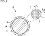
- FIG. 1 is a cross-sectional view showing an example of a multicore optical fiber 10 according to an embodiment of the present invention.
- the multicore optical fiber 10 is an example of an image transmission fiber (image fiber), and the multicore optical fiber 10 has an image circle 12, a jacket portion 14 that covers an outer periphery of the image circle 12, and a coating layer 16 that covers the outer periphery of the jacket portion 14.
- the image circle 12 is a substantially circular pixel region, and the image circle 12 has a configuration in which a plurality of cores 1 penetrate into a common clad 2 in the longitudinal direction of the multicore optical fiber 10 as shown in a partially enlarged part (region surrounded by a two-dot chain line) of FIG. 1 .
- the common clad 2 is shared by the plurality of cores 1.
- a diameter d of the core 1 and a distance D between centers of two adjacent cores are substantially constant in the entire area of the image circle 12.
- Each of the plurality of cores 1 allows propagation of light, and functions as a pixel of an image fiber.
- the diameter of the image circle 12 is not particularly limited, but is, for example, approximately 800 to 2000 ⁇ m. Approximately 5000 to 30000 cores 1 are formed within the image circle 12. With such a configuration, an image formed on one end surface (first end surface) of the multicore optical fiber 10 can be spatially divided and transmitted by the core 1 forming each pixel, and the image can be formed on the other end surface (second end surface).
- the numerical aperture (NA) of the multicore optical fiber 10 is preferably 0.1 or more and 0.45 or less.
- the core 1 is formed of silica glass doped with at least fluorine.
- the relative refractive index difference of the core 1 with respect to the refractive index of silica (SiO 2 ) as a reference is, for example, -0.30% to -0.10%.
- the fluorine concentration of the core 1 is preferably approximately 0.4 to 1.2 wt%.
- the core 1 may contain a dopant other than fluorine, for example, chlorine of 0.01 ppm or more.
- Chlorine may be contained in silica glass in the case of manufacturing porous silica glass using chlorides, such as SiCl 4 , as a raw material or in the case of using a chlorine compound, such as SOCl 2 , for dehydration and sintering of porous silica glass.
- chlorides such as SiCl 4
- a chlorine compound such as SOCl 2
- the core 1 contains fluorine, defects are less likely to be generated in the silica glass even under the radiation environment, and an increase in transmission loss can be suppressed.
- silica glass containing no fluorine is irradiated with radiation, defects are generated in the silica glass due to the action of radiation.
- a transmission loss increase in the visible light region becomes large.
- image observation in the visible light region becomes difficult.
- fluorine has an effect of compensating the defects of silica glass, an increase in transmission loss can be suppressed by using silica glass doped with fluorine.
- the radiation dose is 2 MGy (megagray)
- hydrogen may be doped in the glass (at least the core 1 and a peripheral portion of the core 1).
- the glass is irradiated with radiation, defects are generated in the glass. This causes an increase in transmission loss in the visible light region. Since hydrogen has an effect of compensating the defects of glass, an increase in transmission loss in the visible light region can be suppressed by doping the glass with hydrogen.
- doping hydrogen there is a method of processing the multicore optical fiber 10 in a high-concentration hydrogen (H 2 ) atmosphere. In a case where hydrogen penetrates into the multicore optical fiber 10, hydrogen will be doped into the glass including the core 1 and the clad 2.
- the diameter d of the core 1 is, for example, in the range of 1.0 to 10 ⁇ m.
- the distance D between centers of the adjacent cores 1 is, for example, in the range of 3.0 to 15 ⁇ m.
- the value of the ratio D/d is, for example, approximately 1.02 to approximately 5.0.
- the clad 2 has a refractive index lower than the core 1.
- dopants for reducing the refractive index of silica glass fluorine (F), boron (B), and the like can be mentioned.
- the clad 2 is preferably formed of silica glass doped with at least fluorine. In addition, it is preferable that the fluorine concentration of the clad 2 be higher than the fluorine concentration of the core 1.
- the clad 2 has a two-layer structure including a first clad 4 surrounding the outer periphery of the core 1 and a second clad 3 provided outside the first clad 4, and the refractive index of the second clad 3 is higher than the refractive index of the first clad 4 and lower than the refractive index of the core 1.
- the first clad 4 is provided to ensure the relative refractive index difference required for the waveguide structure of the core 1.
- the relative refractive index difference ( ⁇ ) between the first clad 4 and the core 1 is, for example, 0.8% or more.
- the relative refractive index difference of the first clad 4 with respect to the refractive index of silica (SiO 2 ) as a reference is, for example, -1.2% to -0.9%.
- the fluorine concentration of the first clad 4 is approximately 3.6 to 5.0 wt%.
- the second clad 3 functions as a barrier layer for suppressing the diffusion of fluorine in a case where fluorine-doped silica glass forming the core 1 and the clad 2 is heated.
- the relative refractive index difference ( ⁇ ) between the second clad 3 and the core 1 is, for example, 0.5% or more.
- the relative refractive index difference of the second clad 3 with respect to the refractive index of silica (SiO 2 ) as a reference is, for example, -0.9% to -0.6%. It is preferable that the fluorine concentration of the second clad 3 be lower than the fluorine concentration of the first clad 4.
- the fluorine concentration of the second clad 3 is approximately 2.4 to 3.5 wt%.
- the multicore optical fiber 10 according to the present embodiment can be manufactured by using the following method, for example.
- an optical fiber preform having a core, a first clad surrounding the outer periphery of the core, and a second clad surrounding the outer periphery of the first clad is manufactured using a vapor-phase axial deposition (VAD) method, a chemical vapor deposition (CVD) method, or the like.
- VAD vapor-phase axial deposition
- CVD chemical vapor deposition
- the optical fiber preform has a single core on a cross-section of the optical fiber preform.
- the ratio of the diameter of the first clad to the diameter of the core is approximately 1.01 to 3.0
- the ratio of the diameter of the second clad to the diameter of the core is approximately 1.02 to 5.0.
- a single-core optical fiber having an outer diameter of several tens to several hundreds of micrometers is manufactured by drawing (fiber drawing) the optical fiber preform.
- drawing fiber drawing
- the glass composition and the diameter ratio of the core, the first clad, and the second clad in the single-core optical fiber are the same as the glass composition and the diameter ratio in the optical fiber perform.
- a single-core optical fiber 5 has the core 1 at the center, the first clad 4 at the outer periphery of the core 1, and the second clad 3 at the outermost layer, and the refractive index of the second clad 3 is higher than the refractive index of the first clad 4 and lower than the refractive index of the core 1.
- a plurality of single-core optical fibers 5 are arranged in a glass tube (jacket tube) serving as the jacket portion 14. Then, as shown in FIG. 4 , the clad 2 of each single-core optical fiber 5 is collapsed by melting and elongating the single-core optical fiber and the jacket tube.
- the multicore optical fiber 10 obtained by the elongation is wound around a bobbin to become a product. It is also possible to perform post-processing, such as hydrogen atmosphere processing, on the multicore optical fiber 10.
- FIG. 4 schematically shows a manner in which the jacket portion 14, in which a number of single-core optical fibers 5 are housed, gradually elongates from a large diameter portion 21 to a reduced diameter portion 23 through a taper portion 22.
- size ratios, angles, and the like may be different from actual ones. Elongation is not limited to one step, but can be performed in two or more steps.
- the distribution of the first clad 4 and the second clad 3 in the clad 2 of the obtained multicore optical fiber 10 does not necessarily need to be uniform in a case where this is obtained as a result of melting and collapsing, and it is preferable that the first clad 4 be interposed between the second clad 3 and the core 1.
- part (a) of FIG. 2 shows a state in which the each of first clads 4 is formed separately from each of the cores 1 and the second clad 3 is shared by a number of cores 1 and is formed continuously, the present invention is not limited thereto.
- the coating layer 16 formed of resin or the like be provided on the outer periphery of the multicore optical fiber 10 collapsed in the reduced diameter portion 23.
- resins such as polyimide, silicone, epoxy, and acryl, can be mentioned.
- the multicore optical fiber 10 according to the present embodiment has an excellent radiation resistance property
- the multicore optical fiber 10 according to the present embodiment can also be used in facilities where radioactive materials are handled, such as nuclear power plants, or space influenced by cosmic rays, such as outer space. Since the transmission loss increase amount in the visible light region is low, transmission of a color image is also possible.
- the shape of a pixel region including a number of cores is not limited to the image circle having a circular cross-section, but can have various cross-sectional shapes, such as a square, a hexagon, a polygon, an ellipse, a semicircle, and a fan.
- a light guide for transmitting illumination light in a direction opposite to the image transmission direction can be provided in the image fiber.
- each portion of the core, the first clad, and the second clad may have a substantially uniform composition or refractive index, or may further have a distribution within a predetermined range inside each portion.
- each portion of the core, the first clad, and the second clad may be formed in one step, or one portion may be formed by two or more steps (two or more layers) of laminations.
- a multicore optical fiber was manufactured by drawing a single-core optical fiber formed of fluorine-doped silica glass and having three layers of a core, a first clad, and a second clad, housing a number of single-core optical fibers in a jacket tube formed of pure silica glass, and collapsing the jacket tube onto the single-core optical fibers by melting and elongation.
- the multicore optical fiber was manufactured so that the refractive index of the second clad was lower than the refractive index of the core and higher than the refractive index of the first clad.
- the difference in the refractive indices of the core, the first clad, and the second clad was caused by the difference in fluorine concentration.
- a multicore optical fiber was manufactured by drawing a single-core optical fiber having two layers of a core formed of pure silica glass and a clad formed of fluorine-doped silica glass, housing a number of single-core optical fibers in a jacket tube formed of pure silica glass, and collapsing the jacket tube onto the single-core optical fibers by melting and elongation.
- the multicore optical fiber was manufactured so that the refractive index of the clad was lower than the refractive index of the core.
- Example 1 The multicore optical fiber of Example 1 and the multicore optical fiber of Comparative Example 1 were irradiated with radiation until the radiation dose reached 2 MGy.
- the amount of increase in transmission loss due to irradiation with radiation was calculated by calculating the difference in transmission loss measured before and after irradiation with radiation.
- FIG. 5 shows a graph of the amount of increase in transmission loss (Induced loss) with respect to a wavelength.
- the amount of increase in transmission loss was as high as approximately 20 dB/20 m or more (approximately 1 dB/m or more) in the entire visible light region where the wavelength was approximately 700 nm or less.
- the amount of increase in transmission loss of the multicore optical fiber of Comparative Example 1 was 40 dB/20 m or more (approximately 2 dB/m or more).
- the transmission loss increase amount was as low as approximately 30 dB/20m or less (approximately 1.5 dB/m or less) in a wavelength region of approximately 400 to 900 nm, and was 30 dB/20m or less (approximately 1.5 dB/m or less) at the wavelength of 400 nm. Therefore, image transmission in the visible light region was possible by using the multicore optical fiber of Example 1 even after irradiation with radiation of the radiation dose of 2 MGy.
- a multicore optical fiber was manufactured by drawing a single-core optical fiber having two layers of a core formed of fluorine-doped silica glass and a clad (corresponding to the first clad of Example 1) formed of fluorine-doped silica glass, housing a number of single-core optical fibers in a jacket tube formed of pure silica glass, and collapsing the jacket tube onto the single-core optical fibers by melting and elongation.
- the multicore optical fiber was manufactured so that the refractive index of the clad was lower than the refractive index of the core.
- the multicore optical fiber of the reference example foaming occurred due to diffusion and gasification of fluorine at the time of collapsing the jacket tube onto the single-core optical fibers. As a result, a pixel defect occurred.
- the multicore optical fiber was a multicore optical fiber in which both the core and the clad were formed of silica glass doped with at least fluorine, the multicore optical fiber had an excellent radiation resistance property. Therefore, even after irradiation with radiation of the radiation dose of 2 MGy, image transmission in the visible light region was possible.
- Example 2A is a multicore optical fiber before hydrogen doping
- Example 2B is a multicore optical fiber after hydrogen doping
- Example 2 is a general term for both Example 2A and Example 2B.
- a multicore optical fiber having a pure silica core was manufactured in the same manner as in Comparative Example 1.
- Each of the multicore optical fiber of Example 2A, the multicore optical fiber of Example 2B, and the multicore optical fiber of Comparative Example 2 was irradiated with gamma ( ⁇ ) rays using Co60 as a radiation source under the conditions of a dose rate of 10 kGy/h, an irradiation time of 18 hours, and a total dose of 180 kGy.
- the amount of increase in transmission loss due to irradiation with radiation was calculated by calculating the difference in transmission loss of each multicore optical fiber measured before and after irradiation of gamma rays.
- FIG. 6 shows a graph of the amount of increase in transmission loss (Induced loss) with respect to a wavelength.
- the amount of increase in transmission loss was as high as approximately 20 dB/20 m or more (approximately 1 dB/m or more) in the entire visible light region where the wavelength was approximately 700 nm or less.
- the amount of increase in transmission loss of the multicore optical fiber of Comparative Example 2 was 40 dB/20 m or more (approximately 2 dB/m or more).
- the multicore optical fiber of Example 2A using the fluorine-doped core shows a small transmission loss increase amount in the wavelength region of approximately 400 to 900 nm, and has an excellent radiation resistance property.
- the hydrogen-doped multicore optical fiber of Example 2B shows a very small transmission loss increase amount in the wavelength region of approximately 400 to 900 nm, and has an excellent radiation resistance property.
Landscapes
- Physics & Mathematics (AREA)
- Optics & Photonics (AREA)
- General Physics & Mathematics (AREA)
- Chemical & Material Sciences (AREA)
- Engineering & Computer Science (AREA)
- Geochemistry & Mineralogy (AREA)
- Materials Engineering (AREA)
- Organic Chemistry (AREA)
- Manufacturing & Machinery (AREA)
- Life Sciences & Earth Sciences (AREA)
- General Life Sciences & Earth Sciences (AREA)
- Glass Compositions (AREA)
- Optical Fibers, Optical Fiber Cores, And Optical Fiber Bundles (AREA)
- Manufacture, Treatment Of Glass Fibers (AREA)
Applications Claiming Priority (3)
| Application Number | Priority Date | Filing Date | Title |
|---|---|---|---|
| JP2015154212 | 2015-08-04 | ||
| JP2016078959A JP2017032972A (ja) | 2015-08-04 | 2016-04-11 | マルチコア光ファイバおよびその製造方法 |
| PCT/JP2016/071717 WO2017022546A1 (ja) | 2015-08-04 | 2016-07-25 | マルチコア光ファイバおよびマルチコア光ファイバの製造方法 |
Publications (1)
| Publication Number | Publication Date |
|---|---|
| EP3333604A1 true EP3333604A1 (de) | 2018-06-13 |
Family
ID=57988028
Family Applications (1)
| Application Number | Title | Priority Date | Filing Date |
|---|---|---|---|
| EP16832825.0A Withdrawn EP3333604A1 (de) | 2015-08-04 | 2016-07-25 | Mehrkernglasfaser und verfahren zur herstellung von mehrkernglasfaser |
Country Status (3)
| Country | Link |
|---|---|
| US (1) | US20180224598A1 (de) |
| EP (1) | EP3333604A1 (de) |
| JP (1) | JP2017032972A (de) |
Cited By (3)
| Publication number | Priority date | Publication date | Assignee | Title |
|---|---|---|---|---|
| CN111061011A (zh) * | 2019-11-20 | 2020-04-24 | 桂林电子科技大学 | 一种改进型单模光纤与多芯光纤耦合器及其制备方法 |
| WO2021111337A1 (en) * | 2019-12-04 | 2021-06-10 | Alcon Inc. | Multi-core optical fiber with reduced bubble formation |
| RU2829153C1 (ru) * | 2019-12-04 | 2024-10-24 | Алькон Инк. | Многосердцевинное оптическое волокно с пониженным образованием пузырьков |
Families Citing this family (3)
| Publication number | Priority date | Publication date | Assignee | Title |
|---|---|---|---|---|
| DE102019115146B4 (de) * | 2019-06-05 | 2021-01-14 | Schott Ag | Optisches Gerät, Verwendungen des optischen Gerätes, Fahrzeug oder Beobachtungsstation mit dem optischen Gerät sowie Verfahren zur hochauflösenden Bildübertragung |
| CN111960659A (zh) * | 2019-08-13 | 2020-11-20 | 斯特里特技术有限公司 | 光纤预制棒的烧结方法 |
| CN111290076A (zh) * | 2020-04-21 | 2020-06-16 | 上海大学 | 一种高分辨率的大截面柔软光纤传像束及其制备方法 |
Family Cites Families (3)
| Publication number | Priority date | Publication date | Assignee | Title |
|---|---|---|---|---|
| JPS6075802A (ja) * | 1983-10-03 | 1985-04-30 | Sumitomo Electric Ind Ltd | イメ−ジフアイバの製造方法 |
| JPH0684254B2 (ja) * | 1988-06-29 | 1994-10-26 | 三菱電線工業株式会社 | 耐放射線性マルチプルファイバ |
| JP4699267B2 (ja) * | 2006-04-14 | 2011-06-08 | 株式会社フジクラ | 耐放射線性光ファイバ及びその製造方法 |
-
2016
- 2016-04-11 JP JP2016078959A patent/JP2017032972A/ja active Pending
- 2016-07-25 US US15/749,484 patent/US20180224598A1/en not_active Abandoned
- 2016-07-25 EP EP16832825.0A patent/EP3333604A1/de not_active Withdrawn
Cited By (5)
| Publication number | Priority date | Publication date | Assignee | Title |
|---|---|---|---|---|
| CN111061011A (zh) * | 2019-11-20 | 2020-04-24 | 桂林电子科技大学 | 一种改进型单模光纤与多芯光纤耦合器及其制备方法 |
| WO2021111337A1 (en) * | 2019-12-04 | 2021-06-10 | Alcon Inc. | Multi-core optical fiber with reduced bubble formation |
| US11385401B2 (en) | 2019-12-04 | 2022-07-12 | Alcon Inc. | Multi-core optical fiber with reduced bubble formation |
| RU2829153C1 (ru) * | 2019-12-04 | 2024-10-24 | Алькон Инк. | Многосердцевинное оптическое волокно с пониженным образованием пузырьков |
| AU2020397640B2 (en) * | 2019-12-04 | 2026-04-23 | Alcon Inc. | Multi-core optical fiber with reduced bubble formation |
Also Published As
| Publication number | Publication date |
|---|---|
| JP2017032972A (ja) | 2017-02-09 |
| US20180224598A1 (en) | 2018-08-09 |
Similar Documents
| Publication | Publication Date | Title |
|---|---|---|
| EP3333604A1 (de) | Mehrkernglasfaser und verfahren zur herstellung von mehrkernglasfaser | |
| EP2618189B1 (de) | Optische Faser | |
| EP3009868B1 (de) | Optische faser | |
| US5048923A (en) | Image fiber, image fiber preform, and manufacturing processes thereof | |
| JP2009211066A (ja) | フォトニックバンドギャップ光ファイバ及びその製造方法 | |
| EP4242710A1 (de) | Mehrkern-glasfaser | |
| US9366807B2 (en) | Method of producing preform for coupled multi-core fiber, method of producing coupled multi-core fiber, and coupled multi-core fiber | |
| WO2017022546A1 (ja) | マルチコア光ファイバおよびマルチコア光ファイバの製造方法 | |
| CN1388078A (zh) | 阶跃折射率光纤、预制棒以及制造光纤的方法 | |
| CA3070060A1 (en) | Optical fiber draw assembly and fabricated optical fiber thereof | |
| US9255026B2 (en) | Methods for making active laser fibers | |
| WO2022059699A1 (ja) | マルチコアファイバ | |
| EP3287422A1 (de) | Verfahren zur herstellung von mehrkerniger glasfaser | |
| JP2013205760A (ja) | 光ファイバ及びそれを用いたファンアウトモジュール | |
| WO2024190234A1 (ja) | マルチコア光ファイバ | |
| WO2010088494A1 (en) | Fiber with airlines | |
| JPWO2024190234A5 (de) | ||
| JP6085788B2 (ja) | 遮光ファイバ、バンドルファイバ、遮光ファイバ製造方法、及びバンドルファイバ製造方法 | |
| JP5242896B2 (ja) | イメージファイバ及びその光ファイバ母材 | |
| US11385401B2 (en) | Multi-core optical fiber with reduced bubble formation | |
| JP2002333531A (ja) | 大口径ファイバ | |
| CA3159654C (en) | Multi-core optical fiber with reduced bubble formation | |
| KR100782475B1 (ko) | 광섬유 모재의 제조 방법 및 광섬유 모재 | |
| JPWO2023135944A5 (de) | ||
| JP2017037120A (ja) | 光ファイバ及びその製造方法 |
Legal Events
| Date | Code | Title | Description |
|---|---|---|---|
| STAA | Information on the status of an ep patent application or granted ep patent |
Free format text: STATUS: THE INTERNATIONAL PUBLICATION HAS BEEN MADE |
|
| PUAI | Public reference made under article 153(3) epc to a published international application that has entered the european phase |
Free format text: ORIGINAL CODE: 0009012 |
|
| STAA | Information on the status of an ep patent application or granted ep patent |
Free format text: STATUS: REQUEST FOR EXAMINATION WAS MADE |
|
| 17P | Request for examination filed |
Effective date: 20180124 |
|
| AK | Designated contracting states |
Kind code of ref document: A1 Designated state(s): AL AT BE BG CH CY CZ DE DK EE ES FI FR GB GR HR HU IE IS IT LI LT LU LV MC MK MT NL NO PL PT RO RS SE SI SK SM TR |
|
| AX | Request for extension of the european patent |
Extension state: BA ME |
|
| DAV | Request for validation of the european patent (deleted) | ||
| DAX | Request for extension of the european patent (deleted) | ||
| STAA | Information on the status of an ep patent application or granted ep patent |
Free format text: STATUS: THE APPLICATION HAS BEEN WITHDRAWN |
|
| 18W | Application withdrawn |
Effective date: 20181226 |