EP3333551B1 - Vorrichtung zur messung eines gasstroms in einer leitung - Google Patents
Vorrichtung zur messung eines gasstroms in einer leitung Download PDFInfo
- Publication number
- EP3333551B1 EP3333551B1 EP16203172.8A EP16203172A EP3333551B1 EP 3333551 B1 EP3333551 B1 EP 3333551B1 EP 16203172 A EP16203172 A EP 16203172A EP 3333551 B1 EP3333551 B1 EP 3333551B1
- Authority
- EP
- European Patent Office
- Prior art keywords
- tube
- duct
- input units
- chambers
- axis
- Prior art date
- Legal status (The legal status is an assumption and is not a legal conclusion. Google has not performed a legal analysis and makes no representation as to the accuracy of the status listed.)
- Active
Links
Images


Classifications
-
- G—PHYSICS
- G01—MEASURING; TESTING
- G01F—MEASURING VOLUME, VOLUME FLOW, MASS FLOW OR LIQUID LEVEL; METERING BY VOLUME
- G01F1/00—Measuring the volume flow or mass flow of fluid or fluent solid material wherein the fluid passes through a meter in a continuous flow
- G01F1/05—Measuring the volume flow or mass flow of fluid or fluent solid material wherein the fluid passes through a meter in a continuous flow by using mechanical effects
- G01F1/34—Measuring the volume flow or mass flow of fluid or fluent solid material wherein the fluid passes through a meter in a continuous flow by using mechanical effects by measuring pressure or differential pressure
- G01F1/36—Measuring the volume flow or mass flow of fluid or fluent solid material wherein the fluid passes through a meter in a continuous flow by using mechanical effects by measuring pressure or differential pressure the pressure or differential pressure being created by the use of flow constriction
- G01F1/40—Details of construction of the flow constriction devices
- G01F1/46—Pitot tubes
-
- F—MECHANICAL ENGINEERING; LIGHTING; HEATING; WEAPONS; BLASTING
- F24—HEATING; RANGES; VENTILATING
- F24F—AIR-CONDITIONING; AIR-HUMIDIFICATION; VENTILATION; USE OF AIR CURRENTS FOR SCREENING
- F24F11/00—Control or safety arrangements
- F24F11/70—Control systems characterised by their outputs; Constructional details thereof
- F24F11/72—Control systems characterised by their outputs; Constructional details thereof for controlling the supply of treated air, e.g. its pressure
- F24F11/74—Control systems characterised by their outputs; Constructional details thereof for controlling the supply of treated air, e.g. its pressure for controlling air flow rate or air velocity
-
- G—PHYSICS
- G01—MEASURING; TESTING
- G01P—MEASURING LINEAR OR ANGULAR SPEED, ACCELERATION, DECELERATION, OR SHOCK; INDICATING PRESENCE, ABSENCE, OR DIRECTION, OF MOVEMENT
- G01P5/00—Measuring speed of fluids, e.g. of air stream; Measuring speed of bodies relative to fluids, e.g. of ship, of aircraft
- G01P5/14—Measuring speed of fluids, e.g. of air stream; Measuring speed of bodies relative to fluids, e.g. of ship, of aircraft by measuring differences of pressure in the fluid
- G01P5/16—Measuring speed of fluids, e.g. of air stream; Measuring speed of bodies relative to fluids, e.g. of ship, of aircraft by measuring differences of pressure in the fluid using Pitot tubes, e.g. Machmeter
- G01P5/165—Arrangements or constructions of Pitot tubes
-
- F—MECHANICAL ENGINEERING; LIGHTING; HEATING; WEAPONS; BLASTING
- F24—HEATING; RANGES; VENTILATING
- F24F—AIR-CONDITIONING; AIR-HUMIDIFICATION; VENTILATION; USE OF AIR CURRENTS FOR SCREENING
- F24F2110/00—Control inputs relating to air properties
- F24F2110/40—Pressure, e.g. wind pressure
Definitions
- the invention relates to devices for measuring gas flows, such as air flows. More specifically, the invention pertains to the field of devices capable of measuring gas flows for the purpose of controlling a flow-throttling valve in a duct, such as in a ventilation assembly.
- a solution is provided which is capable of measuring low rate gas flows, suitable for energy-efficient ventilation systems, such as air ventilation systems.
- the capability of measuring air flows is an important feature.
- the purpose may simply be to measure the flow in the duct, so as to be able to calculate a rate or amount of gas provided from a source or to a destination.
- a device for measuring the gas flow is suitably included.
- VAV Variable Air Volume
- State of the art devices for measuring gas flow typically comprise a metal sheet with small measurement tubes on opposite sides, and when the gas flows past the sheet a pressure difference between the two sides is generated, which is proportional to the square of the air speed.
- the sheet In order to be able to measure the level of very low air flows, the sheet needs to block more than 20% of the cross-sectional duct area, which will generate turbulence that will generate noise.
- US20070202795A1 discloses an induced flow fan assembly is provided with a pressure tap arrangement at the outlet for measuring the output flow of the assembly.
- the pressure sensing arrangement includes two rings of piezometers mounted to an outlet windband, one ring at the wider upstream end of the wind band and the outer at the narrower downstream end.
- WO03089883 shows an averaging Pitot tube flow meter having a plurality of circumferentially spaced pitot heads extending radially inward from an inner surface of an annular cylindrical body. Each pitot head includes one or more stagnation pressure holes and a static pressure hole.
- US20160091355 discloses a flow measurement probe which includes an elongate probe having an averaging pitot tube with a plurality of upstream and downstream openings arranged along a length of the elongate probe, and a thermal flow measurement sensor coupled to the elongate probe.
- DE102007019231 describes a controller with has a flap blade arranged in a flow line.
- a difference pressure sensor measures a pressure difference between two pressure measuring points arranged in an impact area of the flap blade and determines a volume flow via the flow line.
- US4344330 discloses an averaging fluid flow sensor, with a pair of tubes around the axis of a duct, each tube having multiple openings to the tube chamber the tubes being directed towards different directions.
- State of the art devices are generally dependent on an extended straight duct portion immediately before the device in order to provide an acceptably homogeneous flow pattern in the duct. This is often problematic, since areas in which to accommodate the ventilation system rarely provide room for such straight duct portions just before e.g. a supply valve or air damper. Bends and turns in the ventilation ducts may thus oftentimes be the source of improper flow measurement, which may cause an imbalance between supply air and exhaust air. This may in turn cause an under pressure or over pressure in the building, resulting in energy loss as air will leak through the outer shell of the building rather than being strictly controlled through the ventilation system.
- a device for measuring gas flow in a duct comprising a first tube and a second tube, which tubes extend about a center axis; each tube having a channel and being provided with a connector and a plurality of distributed input units; each input unit including an opening into the channel and a chamber surrounding the opening, which chamber has an open end and a rear end; wherein the open ends of the chambers on the first tube face a first direction, and the open ends of the chambers on the second tube face a second direction which is different from the first direction, wherein each tube penetrates a side wall of the chambers and runs through the chambers on that tube.
- the input units are evenly distributed about the axis.
- each tube is provided with four input units.
- said chamber is a cylinder member extending along said axis.
- the input units of the first and second tube are pairwise co-located with respect to the center axis, with said rear ends facing each other.
- the device comprises a cylinder member with open ends and a center wall, wherein said cylinder forms both chambers of said pairwise co-located input units.
- said open ends of the chambers of the two tubes face opposite directions along said axis.
- said tubes extend parallel to each other.
- said opening into the channel faces a different direction than the open end of the chamber surrounding said opening, on at least one of the tubes.
- each tube extends in a circular loop.
- a ventilation assembly comprising a ventilation duct; a valve for controlling a gas flow rate through the duct; and a device for measuring gas flow according to any of the embodiments described above, suspended in said duct.
- the ventilation assembly comprises a pressure sensor connected to said connectors for sensing a pressure difference between the first and second tubes; and a control unit connected to the pressure sensor and configured to throttle said valve dependent on the sensed pressure difference.
- said device is suspended between said valve and a duct bend about a turning axis.
- each tube of said device comprises a first pair of input units diametrically disposed parallel to said turning axis; and a second pair of input units diametrically disposed perpendicular to said turning axis.
- Embodiments of the invention are described herein with reference to schematic illustrations of idealized embodiments of the invention. As such, variations from the shapes and relative sizes of the illustrations as a result, for example, of manufacturing techniques and/or tolerances, are to be expected. Thus, embodiments of the invention should not be construed as limited to the particular shapes and relative sizes of regions illustrated herein but are to include deviations in shapes and/or relative sizes that result, for example, from different operational constraints and/or from manufacturing constraints. Thus, the elements illustrated in the figures are schematic in nature and their shapes are not intended to illustrate the actual shape of a region of a device and are not intended to limit the scope of the invention.
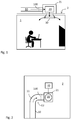
- FIG. 1 presents a scene of use for various embodiments presented herein.
- a supply air duct 10 transports air at an elevated pressure to various rooms 1 of a building complex.
- an air vale in the form of a supply air device 20 is connected to the supply duct 10, for controlling at least the flow of air to the room 1 through an air outlet.
- the supply air device 20 may be arranged in a sealed box 21.
- a diffusor 30 may be connected to the supply air device 20 or the box 21, for convenient distribution of air in the room 1 through the ceiling 2.
- a device 100 for measuring a gas flow is provided. While Fig. 1 illustrates mounting within the ceiling of a room, the device 20 may have its outlet to a wall of the room 1 in an alternative configuration.
- Fig. 2 serves to illustrate the assembly of Fig. 1 , as seen from the ceiling 2.
- a ventilation duct 10 leads air to a suitable position over the inner ceiling of the room 1.
- a valve 20 for controlling a gas flow rate through the duct 1 is provided, and a device 100 is suspended in the duct 1 for measuring gas flow before the valve.
- a control device 40 may comprise a pressure sensor, which is connected to the device 100 and configured to establish a measurement reflecting a flow level dependent on a gas pressure provided from the device 100.
- the control device may further comprise a control unit connected to the pressure sensor and configured to throttle the valve 20 dependent on sensed pressure. More detailed examples of the elements of the assembly of Fig. 2 will be outlined below.
- Fig. 2 illustrates a common installation for a ventilation assembly, where air may be distributed from a ceiling diffusor 30. More specifically, the drawing illustrates a ventilation assembly wherein the device 100 for measuring a gas flow is suspended between the valve 20 and a duct bend 11 about a turning axis 12. In the illustrated embodiment, the duct bends about 90 degrees around the axis 12, but other degrees of turning are of course plausible. Furthermore, the embodiments provided herein relate to installation of the device 100 for measuring a gas flow in a ventilation duct of substantially circular cross-section. However, other shapes are possible, such as a rectangular cross-section. The duct bend shortly before the valve makes it very difficult to reliably measure the gas flow using state of the art flow meter devices.
- FIG. 3-5 shows a member for use in such an example outside of the scope of the present invention
- FIG. 5 illustrates an example outside of the scope of the present invention incorporating a pair of members in a combined arrangement.
- Each such member comprises a tube 101, 102, which extend around a center axis 120.
- Fig. 3 illustrates a perspective view of a first tube 101
- Fig. 4 illustrates a cross-sectional view of the first tube 101, perpendicular to the axis 120 about which the tube 10 loops.
- the tube has a channel 104 formed within a side wall 103, which have a substantially circular shape.
- a connector 105 is formed to provide fluid connection to the channel 104 of the tube 101.
- the connector 105 extends radially outwards from the tube member, but in an alternative example outside of the scope of the present invention the connector may extend in another direction, such as substantially perpendicular to the axis 120.
- the first tube 101 is further provided with a plurality of distributed input units 110, which may be configured to receive a gas pressure from its surroundings.
- each input unit 110 includes an opening 111 into the channel 104 and a chamber 112 surrounding the opening 111.
- the chamber 112 has an open end and a rear end, and the tube channel 104 is thus placed in communicative fluid connection with the exterior of the tube 101, via openings 111 through the open ends of the surrounding chambers 112.
- a member comprising a first tube 101, and a member comprising a second tube 102 that may be configured in a corresponding manner as the first tube 101, are then placed adjacent each other, as illustrated in Fig. 5 .
- the first tube 101 and the second tube 102 are arranged such that the open ends of the chambers 112 on the first tube 101 face a first direction, and the open ends of the chambers 112 on the second tube 102 face a second direction which is different from the first direction.
- the corresponding connectors 105 may conveniently be arranged in substantially the same orientation, as illustrated, so as to alleviate connection of a pressure sensor.
- a pressure sensor may be connected to the connectors 105 and configured to sense a pressure difference between the first 101 and second 102 tubes.
- the open ends 113 of the chambers 112 of the two tubes 101, 102 face opposite directions along said axis 120.
- the device for measuring a gas flow as exemplified in Figs 3-5 is configured to provide an average gas pressure in each tube 101, 102, taken from a plurality of measuring points by means of the distributed input units 110.
- the input units 110 are evenly distributed about the axis 120, and each tube 101, 102 should include at least 3 input units 110.
- the examples outside of the scope of the present invention of Figs 3-5 illustrate how each tube is provided with 4 input units.
- each tube may alternatively comprise 3, 5 or 6 input units.
- the input units 110 of the first 101 and second 102 tube are pairwise co-located with respect to the center axis 120, with said rear ends facing each other. This way, each tube 101, 102 will detect an average pressure at substantially the same measuring points, in terms of angular and radial position with respect to the center axis 120.
- the input units 110 may instead be placed at different radial positions and/or different angular positions, between the first tube and the second tube 102.
- Fig. 7 schematically illustrates a cross-sectional view through a tube 101, 102 and one input unit 110, an example outside of the scope of the present invention.
- the chamber 112 is formed by means of an envelope wall 115, extending from the tube wall 103.
- the envelope wall 115 may have a circular cross-section, as illustrated in Figs 1-6 , or alternatively e.g. a rectangular cross-section.
- the tube wall 103 thus forms the rear end 114 of the chamber 112.
- the rear end 114 is closed to the surrounding atmosphere, whereas the opposing end 113 is open.
- An opening 111 is formed in the tube wall 104, placing the open cavity 116 of the chamber in communicative connection with the tube channel 104.
- Fig. 8 schematically illustrates an embodiment of the invention which is an alternative to the example outside of the scope of the present invention of Fig. 7 , also in a cross-sectional view through a tube 101, 102 and one input unit 110.
- the chamber 112 is formed by means of an envelope wall 115 extending beyond the tube wall 103.
- the tube runs through the chamber 112, penetrating its side wall 115.
- the chamber wall 115 may preferably have a circular cross-section, as illustrated in Figs 1-6 , or alternatively e.g. a rectangular cross-section.
- the rear end 114 of the chamber is separate from the tube wall 103, and may be provided as an integral part of the chamber wall 115 or as a separate end wall member 114.
- An opening 111 is formed in the tube wall 104, placing the open cavity 116 of the chamber 112 in communicative connection with the tube channel 104.
- the opening in the tube wall 103 may be provided centrally, i.e. aligned with the open chamber end 113, as in Fig. 7 .
- the opening 111 may be provided at an angle to the chamber 112, as shown in Fig. 8 .
- the opening 111 in the tube 101, 102 may be open in a direction which is different, e.g. perpendicular, to the direction of the open end 113 of the chamber 112.
- Such an embodiment has the additional advantage that it may be more resistant to collection of dust or other pollution, risking to block the opening 111.
- the openings 111 in the tube wall 103 may be arranged perpendicularly to the open ends 113 of the chambers 112 on the input units 110 of the first tube which is configured to be placed upstream in a ventilation duct.
- the openings 111 in the tube wall 103 may either be arranged perpendicularly to the open ends 113 of the chambers 112 on the input units as in Fig. 8 , or aligned with the open ends 113 of the chambers 112, similar to the orientation of Fig. 7 .
- Fig. 9 illustrates an embodiment in which a common body is employed for the chambers 112 of adjacent input units 110 of the first 101 and second 102 tubes, respectively.
- the common body may comprise a cylinder member with open ends 113 and a center wall 114, wherein said cylinder forms both chambers 112 of said pairwise co-located input units.
- the center wall 114 may be a fixed wall formed in the cylinder, or a separate wall element placed in the cylinder between the two tubes 101 and 102. This arrangement has the further benefit of automatically orienting and placing the input units 110 of the paired tubes 101 and 102 correctly.
- Fig. 10 schematically illustrates a view of an input unit as seen over the first tube 101, in a direction parallel to the center axis 120 about which the tube 101 loops.
- the tube 101, and tube 102 where applicable, extend through a circular side wall 115 of the chamber 112. This may be accomplished by simply pulling the tube 101 through holes of a diameter corresponding to the outer diameter of the tube 101, for snug fitting.
- a seal may be provided at the interface to the tube 101 in the holes in the side wall 155, e.g. by means of a rubber O-ring or an adhesive.
- the opening 11 to the channel 104 of the tube 101 is illustrated in a direction which is perpendicular to the direction of the open end 113 of the chamber 112, as in Figs 8 and 9 .
- the opening 111 may e.g. be oriented in the same way as the open end 113 of the chamber 112, i.e. substantially concentrically with the cylindric cross-section of the chamber wall 115.
- Fig. 11 illustrates an embodiment, similar to that of Fig. 5 , wherein said tubes 101, 102 extend parallel to each other.
- the drawings illustrate embodiments in which each tube extends in a substantially circular loop, but other shapes may be employed.
- pairwise co-located input units 110 of the first 101 and second 102 tube, respectively are provided by means of a common pipe-shaped cylinder forming the chamber walls 115 of those input units, e.g. as provided in Fig. 9 .
- FIG. 12 schematically illustrates a ventilation assembly following the principle drawing of Fig. 2 .
- a valve 20 is provided for controlling a gas flow rate in a ventilation duct 10.
- a device 100 for measuring gas flow is provided in the duct, preferably upstream of the valve 20.
- the device 100 may be configured in accordance with any of the embodiments presented herein, and is thus provided with a pair of connectors 105 to the tube channels 103 of adjacently placed tubes 101 and 102.
- a control device 40 may be provided, which includes a pressure sensor 41, connected to said connectors 105 for sensing a pressure difference between the first 101 and second 102 tubes.
- the control device 40 may further include a control unit 42 connected to the pressure sensor 41 and configured to throttle the valve 20 dependent on the sensed pressure difference. This may be accomplished by means of e.g. a step motor connected to a throttle member, in a well-known manner according to the state of the art.
- Fig. 13 illustrates an embodiment of a ventilation assembly, e.g. in accordance with Fig. 2 , where it is also made clear that the device 100 for measuring the gas flow through a duct 10 is placed closely between a duct bend 11 and a valve 20.
- the device 100 for measuring the gas flow through a duct 10 is placed closely between a duct bend 11 and a valve 20.
- optimum accuracy in the flow rate measurement has been obtained when the each tube of the device 100 is arranged with a first pair of input units 110 diametrically disposed parallel to the turning axis 12 of the duct bend 11, and a second pair of input units 110 diametrically disposed perpendicular to said turning axis 12.
- the valve 20 may comprise an inner tube 22 configured to pass gas from the duct into the box 21 and further out through a distributer 30. Throttling may be obtained by selectively decreasing the size of the exposed surface of the inner tube 22, by covering it with an outer tube 23.
- the outer tube may be displaced along the inner tube 22 e.g. be means of a motor 24, turning a long screw 25 about a nut 26 in the outer tube 23.
- the motor 24, which may be under control of a control unit 42 of a control device 41, as exemplified in Fig. 12 , may in this embodiment be suspended centrally at the device 100 for measuring the gas flow.
- Fig. 14 illustrates an embodiment, which may be used in the assembly embodiment of Fig. 13 .
- the ventilation assembly comprises a suspension device 140 for suspending a motor 24 for setting a throttle position of a valve 20.
- the motor 24 is preferably suspended at the center axis 120 of the device 100 for measuring a gas flow.
- the suspension device 140 may be configured to suspend both the device 100 and the motor 24, as exemplified in the drawing, by means of a bracket or similar, connected to a duct wall 13.
- a device 100 configured in accordance with the invention is capable of providing accurate flow readings even at very low flows.
- Test have shown that for various embodiments, accurate measurement of air flows of down to the range of 2-4 l/s can be obtained.
- test have shown that accurate flow rate measurements can be obtained even when the device 100 is suspended centrally in a duct within 50 cm after a duct bend 11.
- the device 100 is suspended in the duct 10 such that the input units 110 are evenly distributed around its center axis 120, which substantially coincides with a center axis of the duct 10.
- the device 100 may be configured to operate in a duct 10 of a predetermined inner diameter D, wherein the device has input units 110 are located on a tube 101, 102 with a diameter d, where d may be 3-6 cm smaller than D, or even 4-5 mm smaller.
- the input units 110 may be pairwise arranged for the first 101 and second tube 102 by means of a common chamber 112, wherein each such pair is diametrically arranged with a corresponding pair of input units 110, with respect to the center axis 120. This may be true specifically for a device 100 embodiment having an even number of input units 110 on each tube 101, 102. For large ducts, the device 100 may be configured with more than four input units 110 per tube.
- Each tube 101, 102 may e.g. be a hose of nylon or other plastic material, or a metal such as aluminum, and may have an outer diameter of 3-10 mm, such as 4-8, e.g. 6 mm, and an outer diameter of 2-8 mm, such as 3-6 mm, e.g. 4 mm.
- the opening 111 in each input unit may be 0.5-3 mm, e.g. 1-2 mm.
- the chambers 112 may be formed with plastic walls, e.g. from a pipe of PVC, nylon or other plastic, or a metal, with a 10-20 mm outer diameter, such as 16 mm.
- An embodiment of the device 100 such as shown e.g. in Fig. 11 is configured to sense an average total pressure at the input units 110 of the upstream-facing first tube 101.
- the device 100 is further configured to sense an average total pressure at the input units 110 of the downstream-facing second tube 102, for which a certain dynamic under pressure may be obtained.
- the embodiment with pipe-shaped input unit chambers 112 has been tested and found to generate very little sound.
Landscapes
- Physics & Mathematics (AREA)
- Engineering & Computer Science (AREA)
- Fluid Mechanics (AREA)
- General Physics & Mathematics (AREA)
- Chemical & Material Sciences (AREA)
- Combustion & Propulsion (AREA)
- Mechanical Engineering (AREA)
- General Engineering & Computer Science (AREA)
- Aviation & Aerospace Engineering (AREA)
- Measuring Volume Flow (AREA)
Claims (14)
- Vorrichtung (100) zum Messen eines Gasstroms in einer Leitung (10), Folgendes umfassend
ein erstes Rohr (101) und ein zweites Rohr (102), wobei sich die Rohre um eine Mittenachse (120) herum erstrecken;
wobei jedes Rohr einen Kanal (104) aufweist und mit einem Verbinder (105) und mehreren verteilten Eingangseinheiten (110) versehen ist;
wobei jede Eingangseinheit eine Öffnung (111) in den Kanal umfasst,
dadurch gekennzeichnet, dass jede Eingangseinheit eine Kammer (112) umfasst, welche die Öffnung umgibt, wobei die Kammer ein offenes Ende (113) und ein geschlossenes hinteres Ende (114) aufweist;
wobei die offenen Enden (113) der Kammern auf dem ersten Rohr (101) in eine erste Richtung weisen und die offenen Enden der Kammern auf dem zweiten Rohr (102) in eine zweite Richtung weisen, die von der ersten Richtung verschieden ist; und
wobei jedes Rohr eine Seitenwand der Kammern durchdringt und durch die Kammern (112) auf diesem Rohr verläuft. - Vorrichtung nach Anspruch 1, wobei die Eingangseinheiten gleichmäßig um die Achse herum verteilt sind.
- Vorrichtung nach einem der vorhergehenden Ansprüche, wobei jedes Rohr mit vier Eingangseinheiten versehen ist.
- Vorrichtung nach einem der vorhergehenden Ansprüche, wobei die Kammer ein Zylinderglied ist, das sich entlang der Achse erstreckt.
- Vorrichtung nach einem der vorhergehenden Ansprüche, wobei die Eingangseinheiten des ersten und des zweiten Rohrs hinsichtlich der Mittenachse paarweise zusammen angeordnet sind, wobei sich die hinteren Enden einander gegenüber stehen.
- Vorrichtung nach Anspruch 5, ein Zylinderglied mit offenen Enden und einer Mittenwand (114) umfassend, wobei der Zylinder beide Kammern der paarweise zusammen angeordneten Eingangseinheiten ausbildet.
- Vorrichtung nach einem der vorhergehenden Ansprüche, wobei die offenen Enden der Kammern der beiden Rohre (101, 102) in entgegengesetzte Richtungen entlang der Achse weisen.
- Vorrichtung nach einem der vorhergehenden Ansprüche, wobei sich die Rohre parallel zueinander erstrecken.
- Vorrichtung nach einem der vorhergehenden Ansprüche, wobei die Öffnung (111) von mindestens einem der Rohre (101, 102) in den Kanal in eine Richtung weist, die von der des offenen Endes (113) der Kammer, welche die Öffnung umgibt, verschieden ist.
- Vorrichtung nach einem der vorhergehenden Ansprüche, wobei sich jedes Rohr in einer kreisförmigen Schleife erstreckt.
- Belüftungsanordnung, Folgendes umfassend
eine Belüftungsleitung (10);
ein Ventil (20) zum Steuern einer Gasstromrate durch die Leitung; und
eine Vorrichtung (100) zum Messen eines Gasstroms nach einem der vorhergehenden Ansprüche, die in der Leitung aufgehängt ist. - Belüftungsanordnung nach Anspruch 11, Folgendes umfassend
einen Drucksensor (41), der mit den Verbindern (105) zum Messen einer Druckdifferenz zwischen dem ersten und dem zweiten Rohr (101, 102) verbunden ist; und
eine Steuerungseinheit (42), die mit dem Drucksensor verbunden ist und eingerichtet ist, das Ventil abhängig von der gemessenen Druckdifferenz zu drosseln. - Belüftungsanordnung nach Anspruch 11 oder 12, wobei die Vorrichtung (100) zwischen dem Ventil (20) und einer Leitungsbiegung (11) um eine Drehachse (12) herum aufgehängt ist.
- Belüftungsanordnung nach Anspruch 13, wobei jedes Rohr der Vorrichtung Folgendes umfasst
ein erstes Paar Eingangseinheiten, die parallel zu der Drehachse diametral angeordnet sind; und
ein zweites Paar Eingangseinheiten, die senkrecht zu der Drehachse diametral angeordnet sind.
Priority Applications (4)
| Application Number | Priority Date | Filing Date | Title |
|---|---|---|---|
| PL16203172T PL3333551T3 (pl) | 2016-12-09 | 2016-12-09 | Urządzenie do mierzenia przepływu gazu w przewodzie |
| EP16203172.8A EP3333551B1 (de) | 2016-12-09 | 2016-12-09 | Vorrichtung zur messung eines gasstroms in einer leitung |
| LT16203172T LT3333551T (lt) | 2016-12-09 | 2016-12-09 | Dujų srauto ortakyje matavimo prietaisas |
| DK16203172.8T DK3333551T3 (da) | 2016-12-09 | 2016-12-09 | Anordning til måling af gasstrømning i en kanal |
Applications Claiming Priority (1)
| Application Number | Priority Date | Filing Date | Title |
|---|---|---|---|
| EP16203172.8A EP3333551B1 (de) | 2016-12-09 | 2016-12-09 | Vorrichtung zur messung eines gasstroms in einer leitung |
Publications (2)
| Publication Number | Publication Date |
|---|---|
| EP3333551A1 EP3333551A1 (de) | 2018-06-13 |
| EP3333551B1 true EP3333551B1 (de) | 2019-10-02 |
Family
ID=57542802
Family Applications (1)
| Application Number | Title | Priority Date | Filing Date |
|---|---|---|---|
| EP16203172.8A Active EP3333551B1 (de) | 2016-12-09 | 2016-12-09 | Vorrichtung zur messung eines gasstroms in einer leitung |
Country Status (4)
| Country | Link |
|---|---|
| EP (1) | EP3333551B1 (de) |
| DK (1) | DK3333551T3 (de) |
| LT (1) | LT3333551T (de) |
| PL (1) | PL3333551T3 (de) |
Citations (1)
| Publication number | Priority date | Publication date | Assignee | Title |
|---|---|---|---|---|
| US4375769A (en) * | 1981-07-06 | 1983-03-08 | Brandt Industries, Inc. | Transverse-duct insertion type pressure averaging primary |
Family Cites Families (6)
| Publication number | Priority date | Publication date | Assignee | Title |
|---|---|---|---|---|
| US4344330A (en) * | 1981-02-13 | 1982-08-17 | The Trane Company | Average fluid flow sensor |
| CA1210610A (en) * | 1984-05-09 | 1986-09-02 | Roger P. Engelke | Device for sensing the volumetric flow rate of air in a duct |
| KR100433719B1 (ko) | 2002-01-10 | 2004-05-31 | 주식회사 서진인스텍 | 유량측정용 피토조립체 |
| US20070202795A1 (en) | 2006-02-24 | 2007-08-30 | Greenheck Fan Corporation | Induced flow fan with outlet flow measurement |
| DE102007019231B3 (de) | 2007-04-24 | 2008-07-10 | Werner Dipl.-Ing. Wildeboer | Elektronischer Volumenstromregler |
| US9804011B2 (en) | 2014-09-30 | 2017-10-31 | Dieterich Standard, Inc. | Flow measurement probe with pitot tube and thermal flow measurement |
-
2016
- 2016-12-09 DK DK16203172.8T patent/DK3333551T3/da active
- 2016-12-09 PL PL16203172T patent/PL3333551T3/pl unknown
- 2016-12-09 EP EP16203172.8A patent/EP3333551B1/de active Active
- 2016-12-09 LT LT16203172T patent/LT3333551T/lt unknown
Patent Citations (1)
| Publication number | Priority date | Publication date | Assignee | Title |
|---|---|---|---|---|
| US4375769A (en) * | 1981-07-06 | 1983-03-08 | Brandt Industries, Inc. | Transverse-duct insertion type pressure averaging primary |
Also Published As
| Publication number | Publication date |
|---|---|
| DK3333551T3 (da) | 2020-01-20 |
| EP3333551A1 (de) | 2018-06-13 |
| PL3333551T3 (pl) | 2020-04-30 |
| LT3333551T (lt) | 2019-12-10 |
Similar Documents
| Publication | Publication Date | Title |
|---|---|---|
| US6557574B2 (en) | Pressure based flow rate measurement device integrated with blades of a damper | |
| US10451461B2 (en) | Venturi air flow sensor and control system | |
| US8757008B1 (en) | Powered capture hood | |
| US4344330A (en) | Average fluid flow sensor | |
| US6237426B1 (en) | Airflow sensor | |
| US6487918B1 (en) | Airflow sensor for averaging total pressure | |
| US10527313B2 (en) | Building airflow measuring system and method | |
| US12228304B2 (en) | Air volume control valve capable of accurately measuring air volume | |
| CN210037863U (zh) | 一种复合型测烟气流速装置 | |
| US7243556B2 (en) | Airflow sensor | |
| CN111707320A (zh) | 旋流燃烧器二次风测速装置 | |
| US11519839B2 (en) | Pressure probe including multiple orfices for measuring air pressure in varying airflow systems | |
| KR101590520B1 (ko) | 피토 튜브를 이용한 복합형 덕트 풍량 측정 장치 및 측정 방법 | |
| JP2011122795A (ja) | 風量調整装置 | |
| KR102448002B1 (ko) | 복합 벤추리 에어밸브 및 이를 이용한 풍량 제어 방법 | |
| EP3333551A1 (de) | Vorrichtung zur messung eines gasstroms in einer leitung | |
| US6450043B1 (en) | Probe for monitoring intake air volume and method | |
| CN220622773U (zh) | 一种基于压力控制的智能型风量调节阀 | |
| CN217482955U (zh) | 一种含有风量调节阀的空调通风系统 | |
| JPH04133108A (ja) | 流量制御バルブ及びこのバルブを用いた流量測定装置 | |
| JPH0576566B2 (de) | ||
| CN105043752A (zh) | 一种风洞式风机盘管风量的检测装置 | |
| CN204944814U (zh) | 一种风洞式风机盘管风量的检测装置 | |
| US20240201037A1 (en) | Measurement probe for measuring pressure inside air duct and measurement system for measuring pressure difference | |
| JP5925439B2 (ja) | 基準圧計測補助具および基準圧計測方法 |
Legal Events
| Date | Code | Title | Description |
|---|---|---|---|
| PUAI | Public reference made under article 153(3) epc to a published international application that has entered the european phase |
Free format text: ORIGINAL CODE: 0009012 |
|
| STAA | Information on the status of an ep patent application or granted ep patent |
Free format text: STATUS: THE APPLICATION HAS BEEN PUBLISHED |
|
| AK | Designated contracting states |
Kind code of ref document: A1 Designated state(s): AL AT BE BG CH CY CZ DE DK EE ES FI FR GB GR HR HU IE IS IT LI LT LU LV MC MK MT NL NO PL PT RO RS SE SI SK SM TR |
|
| AX | Request for extension of the european patent |
Extension state: BA ME |
|
| STAA | Information on the status of an ep patent application or granted ep patent |
Free format text: STATUS: REQUEST FOR EXAMINATION WAS MADE |
|
| 17P | Request for examination filed |
Effective date: 20181210 |
|
| RBV | Designated contracting states (corrected) |
Designated state(s): AL AT BE BG CH CY CZ DE DK EE ES FI FR GB GR HR HU IE IS IT LI LT LU LV MC MK MT NL NO PL PT RO RS SE SI SK SM TR |
|
| RIC1 | Information provided on ipc code assigned before grant |
Ipc: G01F 1/40 20060101ALI20170530BHEP Ipc: F24F 11/00 20180101ALI20170530BHEP Ipc: G01P 5/165 20060101ALI20170530BHEP Ipc: F24F 11/04 20060101ALI20170530BHEP Ipc: G01F 1/36 20060101AFI20170530BHEP Ipc: G01F 1/46 20060101ALI20170530BHEP |
|
| REG | Reference to a national code |
Ref country code: DE Ref legal event code: R079 Ref document number: 602016021597 Country of ref document: DE Free format text: PREVIOUS MAIN CLASS: G01F0001360000 Ipc: G01F0001460000 |
|
| RIC1 | Information provided on ipc code assigned before grant |
Ipc: G01F 1/46 20060101AFI20190415BHEP Ipc: G01P 5/165 20060101ALI20190415BHEP Ipc: F24F 11/74 20180101ALI20190415BHEP Ipc: F24F 110/40 20180101ALN20190415BHEP |
|
| GRAP | Despatch of communication of intention to grant a patent |
Free format text: ORIGINAL CODE: EPIDOSNIGR1 |
|
| STAA | Information on the status of an ep patent application or granted ep patent |
Free format text: STATUS: GRANT OF PATENT IS INTENDED |
|
| INTG | Intention to grant announced |
Effective date: 20190524 |
|
| GRAS | Grant fee paid |
Free format text: ORIGINAL CODE: EPIDOSNIGR3 |
|
| GRAA | (expected) grant |
Free format text: ORIGINAL CODE: 0009210 |
|
| STAA | Information on the status of an ep patent application or granted ep patent |
Free format text: STATUS: THE PATENT HAS BEEN GRANTED |
|
| AK | Designated contracting states |
Kind code of ref document: B1 Designated state(s): AL AT BE BG CH CY CZ DE DK EE ES FI FR GB GR HR HU IE IS IT LI LT LU LV MC MK MT NL NO PL PT RO RS SE SI SK SM TR |
|
| REG | Reference to a national code |
Ref country code: GB Ref legal event code: FG4D |
|
| REG | Reference to a national code |
Ref country code: CH Ref legal event code: EP Ref country code: AT Ref legal event code: REF Ref document number: 1186694 Country of ref document: AT Kind code of ref document: T Effective date: 20191015 |
|
| REG | Reference to a national code |
Ref country code: DE Ref legal event code: R096 Ref document number: 602016021597 Country of ref document: DE |
|
| REG | Reference to a national code |
Ref country code: IE Ref legal event code: FG4D |
|
| REG | Reference to a national code |
Ref country code: NO Ref legal event code: T2 Effective date: 20191002 |
|
| REG | Reference to a national code |
Ref country code: NL Ref legal event code: FP |
|
| REG | Reference to a national code |
Ref country code: EE Ref legal event code: FG4A Ref document number: E018428 Country of ref document: EE Effective date: 20191114 |
|
| REG | Reference to a national code |
Ref country code: DK Ref legal event code: T3 Effective date: 20200113 |
|
| REG | Reference to a national code |
Ref country code: SE Ref legal event code: TRGR |
|
| REG | Reference to a national code |
Ref country code: AT Ref legal event code: MK05 Ref document number: 1186694 Country of ref document: AT Kind code of ref document: T Effective date: 20191002 |
|
| PG25 | Lapsed in a contracting state [announced via postgrant information from national office to epo] |
Ref country code: AT Free format text: LAPSE BECAUSE OF FAILURE TO SUBMIT A TRANSLATION OF THE DESCRIPTION OR TO PAY THE FEE WITHIN THE PRESCRIBED TIME-LIMIT Effective date: 20191002 Ref country code: ES Free format text: LAPSE BECAUSE OF FAILURE TO SUBMIT A TRANSLATION OF THE DESCRIPTION OR TO PAY THE FEE WITHIN THE PRESCRIBED TIME-LIMIT Effective date: 20191002 Ref country code: GR Free format text: LAPSE BECAUSE OF FAILURE TO SUBMIT A TRANSLATION OF THE DESCRIPTION OR TO PAY THE FEE WITHIN THE PRESCRIBED TIME-LIMIT Effective date: 20200103 Ref country code: PT Free format text: LAPSE BECAUSE OF FAILURE TO SUBMIT A TRANSLATION OF THE DESCRIPTION OR TO PAY THE FEE WITHIN THE PRESCRIBED TIME-LIMIT Effective date: 20200203 Ref country code: BG Free format text: LAPSE BECAUSE OF FAILURE TO SUBMIT A TRANSLATION OF THE DESCRIPTION OR TO PAY THE FEE WITHIN THE PRESCRIBED TIME-LIMIT Effective date: 20200102 |
|
| PG25 | Lapsed in a contracting state [announced via postgrant information from national office to epo] |
Ref country code: HR Free format text: LAPSE BECAUSE OF FAILURE TO SUBMIT A TRANSLATION OF THE DESCRIPTION OR TO PAY THE FEE WITHIN THE PRESCRIBED TIME-LIMIT Effective date: 20191002 Ref country code: RS Free format text: LAPSE BECAUSE OF FAILURE TO SUBMIT A TRANSLATION OF THE DESCRIPTION OR TO PAY THE FEE WITHIN THE PRESCRIBED TIME-LIMIT Effective date: 20191002 Ref country code: CZ Free format text: LAPSE BECAUSE OF FAILURE TO SUBMIT A TRANSLATION OF THE DESCRIPTION OR TO PAY THE FEE WITHIN THE PRESCRIBED TIME-LIMIT Effective date: 20191002 |
|
| PG25 | Lapsed in a contracting state [announced via postgrant information from national office to epo] |
Ref country code: AL Free format text: LAPSE BECAUSE OF FAILURE TO SUBMIT A TRANSLATION OF THE DESCRIPTION OR TO PAY THE FEE WITHIN THE PRESCRIBED TIME-LIMIT Effective date: 20191002 |
|
| REG | Reference to a national code |
Ref country code: DE Ref legal event code: R097 Ref document number: 602016021597 Country of ref document: DE |
|
| PG25 | Lapsed in a contracting state [announced via postgrant information from national office to epo] |
Ref country code: RO Free format text: LAPSE BECAUSE OF FAILURE TO SUBMIT A TRANSLATION OF THE DESCRIPTION OR TO PAY THE FEE WITHIN THE PRESCRIBED TIME-LIMIT Effective date: 20191002 |
|
| REG | Reference to a national code |
Ref country code: CH Ref legal event code: PL |
|
| PLBE | No opposition filed within time limit |
Free format text: ORIGINAL CODE: 0009261 |
|
| STAA | Information on the status of an ep patent application or granted ep patent |
Free format text: STATUS: NO OPPOSITION FILED WITHIN TIME LIMIT |
|
| REG | Reference to a national code |
Ref country code: BE Ref legal event code: MM Effective date: 20191231 |
|
| PG25 | Lapsed in a contracting state [announced via postgrant information from national office to epo] |
Ref country code: IT Free format text: LAPSE BECAUSE OF FAILURE TO SUBMIT A TRANSLATION OF THE DESCRIPTION OR TO PAY THE FEE WITHIN THE PRESCRIBED TIME-LIMIT Effective date: 20191002 Ref country code: SK Free format text: LAPSE BECAUSE OF FAILURE TO SUBMIT A TRANSLATION OF THE DESCRIPTION OR TO PAY THE FEE WITHIN THE PRESCRIBED TIME-LIMIT Effective date: 20191002 Ref country code: SM Free format text: LAPSE BECAUSE OF FAILURE TO SUBMIT A TRANSLATION OF THE DESCRIPTION OR TO PAY THE FEE WITHIN THE PRESCRIBED TIME-LIMIT Effective date: 20191002 Ref country code: MC Free format text: LAPSE BECAUSE OF FAILURE TO SUBMIT A TRANSLATION OF THE DESCRIPTION OR TO PAY THE FEE WITHIN THE PRESCRIBED TIME-LIMIT Effective date: 20191002 |
|
| 26N | No opposition filed |
Effective date: 20200703 |
|
| PG25 | Lapsed in a contracting state [announced via postgrant information from national office to epo] |
Ref country code: LU Free format text: LAPSE BECAUSE OF NON-PAYMENT OF DUE FEES Effective date: 20191209 |
|
| PG25 | Lapsed in a contracting state [announced via postgrant information from national office to epo] |
Ref country code: BE Free format text: LAPSE BECAUSE OF NON-PAYMENT OF DUE FEES Effective date: 20191231 Ref country code: CH Free format text: LAPSE BECAUSE OF NON-PAYMENT OF DUE FEES Effective date: 20191231 Ref country code: SI Free format text: LAPSE BECAUSE OF FAILURE TO SUBMIT A TRANSLATION OF THE DESCRIPTION OR TO PAY THE FEE WITHIN THE PRESCRIBED TIME-LIMIT Effective date: 20191002 Ref country code: LI Free format text: LAPSE BECAUSE OF NON-PAYMENT OF DUE FEES Effective date: 20191231 |
|
| PG25 | Lapsed in a contracting state [announced via postgrant information from national office to epo] |
Ref country code: CY Free format text: LAPSE BECAUSE OF FAILURE TO SUBMIT A TRANSLATION OF THE DESCRIPTION OR TO PAY THE FEE WITHIN THE PRESCRIBED TIME-LIMIT Effective date: 20191002 |
|
| PG25 | Lapsed in a contracting state [announced via postgrant information from national office to epo] |
Ref country code: MT Free format text: LAPSE BECAUSE OF FAILURE TO SUBMIT A TRANSLATION OF THE DESCRIPTION OR TO PAY THE FEE WITHIN THE PRESCRIBED TIME-LIMIT Effective date: 20191002 Ref country code: HU Free format text: LAPSE BECAUSE OF FAILURE TO SUBMIT A TRANSLATION OF THE DESCRIPTION OR TO PAY THE FEE WITHIN THE PRESCRIBED TIME-LIMIT; INVALID AB INITIO Effective date: 20161209 |
|
| PG25 | Lapsed in a contracting state [announced via postgrant information from national office to epo] |
Ref country code: TR Free format text: LAPSE BECAUSE OF FAILURE TO SUBMIT A TRANSLATION OF THE DESCRIPTION OR TO PAY THE FEE WITHIN THE PRESCRIBED TIME-LIMIT Effective date: 20191002 |
|
| PG25 | Lapsed in a contracting state [announced via postgrant information from national office to epo] |
Ref country code: MK Free format text: LAPSE BECAUSE OF FAILURE TO SUBMIT A TRANSLATION OF THE DESCRIPTION OR TO PAY THE FEE WITHIN THE PRESCRIBED TIME-LIMIT Effective date: 20191002 |
|
| PGFP | Annual fee paid to national office [announced via postgrant information from national office to epo] |
Ref country code: IS Payment date: 20251229 Year of fee payment: 10 |
|
| PGFP | Annual fee paid to national office [announced via postgrant information from national office to epo] |
Ref country code: LT Payment date: 20251118 Year of fee payment: 10 Ref country code: GB Payment date: 20251219 Year of fee payment: 10 |
|
| PGFP | Annual fee paid to national office [announced via postgrant information from national office to epo] |
Ref country code: NO Payment date: 20251219 Year of fee payment: 10 |
|
| PGFP | Annual fee paid to national office [announced via postgrant information from national office to epo] |
Ref country code: FI Payment date: 20251216 Year of fee payment: 10 Ref country code: DK Payment date: 20251222 Year of fee payment: 10 |
|
| PGFP | Annual fee paid to national office [announced via postgrant information from national office to epo] |
Ref country code: NL Payment date: 20251217 Year of fee payment: 10 Ref country code: FR Payment date: 20251211 Year of fee payment: 10 |
|
| PGFP | Annual fee paid to national office [announced via postgrant information from national office to epo] |
Ref country code: SE Payment date: 20251219 Year of fee payment: 10 |
|
| PGFP | Annual fee paid to national office [announced via postgrant information from national office to epo] |
Ref country code: IE Payment date: 20251215 Year of fee payment: 10 |
|
| PGFP | Annual fee paid to national office [announced via postgrant information from national office to epo] |
Ref country code: LV Payment date: 20251219 Year of fee payment: 10 |
|
| PGFP | Annual fee paid to national office [announced via postgrant information from national office to epo] |
Ref country code: PL Payment date: 20251112 Year of fee payment: 10 |
|
| PGFP | Annual fee paid to national office [announced via postgrant information from national office to epo] |
Ref country code: EE Payment date: 20251231 Year of fee payment: 10 |
|
| PGFP | Annual fee paid to national office [announced via postgrant information from national office to epo] |
Ref country code: DE Payment date: 20251222 Year of fee payment: 10 |