EP3333441B1 - Dispositif de freinage électrique - Google Patents
Dispositif de freinage électrique Download PDFInfo
- Publication number
- EP3333441B1 EP3333441B1 EP16832865.6A EP16832865A EP3333441B1 EP 3333441 B1 EP3333441 B1 EP 3333441B1 EP 16832865 A EP16832865 A EP 16832865A EP 3333441 B1 EP3333441 B1 EP 3333441B1
- Authority
- EP
- European Patent Office
- Prior art keywords
- linear motion
- housing
- motion mechanism
- reduction gear
- brake system
- Prior art date
- Legal status (The legal status is an assumption and is not a legal conclusion. Google has not performed a legal analysis and makes no representation as to the accuracy of the status listed.)
- Active
Links
Images




Classifications
-
- B—PERFORMING OPERATIONS; TRANSPORTING
- B60—VEHICLES IN GENERAL
- B60T—VEHICLE BRAKE CONTROL SYSTEMS OR PARTS THEREOF; BRAKE CONTROL SYSTEMS OR PARTS THEREOF, IN GENERAL; ARRANGEMENT OF BRAKING ELEMENTS ON VEHICLES IN GENERAL; PORTABLE DEVICES FOR PREVENTING UNWANTED MOVEMENT OF VEHICLES; VEHICLE MODIFICATIONS TO FACILITATE COOLING OF BRAKES
- B60T13/00—Transmitting braking action from initiating means to ultimate brake actuator with power assistance or drive; Brake systems incorporating such transmitting means, e.g. air-pressure brake systems
- B60T13/74—Transmitting braking action from initiating means to ultimate brake actuator with power assistance or drive; Brake systems incorporating such transmitting means, e.g. air-pressure brake systems with electrical assistance or drive
- B60T13/745—Transmitting braking action from initiating means to ultimate brake actuator with power assistance or drive; Brake systems incorporating such transmitting means, e.g. air-pressure brake systems with electrical assistance or drive acting on a hydraulic system, e.g. a master cylinder
-
- F—MECHANICAL ENGINEERING; LIGHTING; HEATING; WEAPONS; BLASTING
- F16—ENGINEERING ELEMENTS AND UNITS; GENERAL MEASURES FOR PRODUCING AND MAINTAINING EFFECTIVE FUNCTIONING OF MACHINES OR INSTALLATIONS; THERMAL INSULATION IN GENERAL
- F16D—COUPLINGS FOR TRANSMITTING ROTATION; CLUTCHES; BRAKES
- F16D55/00—Brakes with substantially-radial braking surfaces pressed together in axial direction, e.g. disc brakes
- F16D55/02—Brakes with substantially-radial braking surfaces pressed together in axial direction, e.g. disc brakes with axially-movable discs or pads pressed against axially-located rotating members
- F16D55/22—Brakes with substantially-radial braking surfaces pressed together in axial direction, e.g. disc brakes with axially-movable discs or pads pressed against axially-located rotating members by clamping an axially-located rotating disc between movable braking members, e.g. movable brake discs or brake pads
- F16D55/224—Brakes with substantially-radial braking surfaces pressed together in axial direction, e.g. disc brakes with axially-movable discs or pads pressed against axially-located rotating members by clamping an axially-located rotating disc between movable braking members, e.g. movable brake discs or brake pads with a common actuating member for the braking members
- F16D55/225—Brakes with substantially-radial braking surfaces pressed together in axial direction, e.g. disc brakes with axially-movable discs or pads pressed against axially-located rotating members by clamping an axially-located rotating disc between movable braking members, e.g. movable brake discs or brake pads with a common actuating member for the braking members the braking members being brake pads
- F16D55/226—Brakes with substantially-radial braking surfaces pressed together in axial direction, e.g. disc brakes with axially-movable discs or pads pressed against axially-located rotating members by clamping an axially-located rotating disc between movable braking members, e.g. movable brake discs or brake pads with a common actuating member for the braking members the braking members being brake pads in which the common actuating member is moved axially, e.g. floating caliper disc brakes
-
- B—PERFORMING OPERATIONS; TRANSPORTING
- B60—VEHICLES IN GENERAL
- B60T—VEHICLE BRAKE CONTROL SYSTEMS OR PARTS THEREOF; BRAKE CONTROL SYSTEMS OR PARTS THEREOF, IN GENERAL; ARRANGEMENT OF BRAKING ELEMENTS ON VEHICLES IN GENERAL; PORTABLE DEVICES FOR PREVENTING UNWANTED MOVEMENT OF VEHICLES; VEHICLE MODIFICATIONS TO FACILITATE COOLING OF BRAKES
- B60T13/00—Transmitting braking action from initiating means to ultimate brake actuator with power assistance or drive; Brake systems incorporating such transmitting means, e.g. air-pressure brake systems
- B60T13/74—Transmitting braking action from initiating means to ultimate brake actuator with power assistance or drive; Brake systems incorporating such transmitting means, e.g. air-pressure brake systems with electrical assistance or drive
-
- B—PERFORMING OPERATIONS; TRANSPORTING
- B60—VEHICLES IN GENERAL
- B60T—VEHICLE BRAKE CONTROL SYSTEMS OR PARTS THEREOF; BRAKE CONTROL SYSTEMS OR PARTS THEREOF, IN GENERAL; ARRANGEMENT OF BRAKING ELEMENTS ON VEHICLES IN GENERAL; PORTABLE DEVICES FOR PREVENTING UNWANTED MOVEMENT OF VEHICLES; VEHICLE MODIFICATIONS TO FACILITATE COOLING OF BRAKES
- B60T13/00—Transmitting braking action from initiating means to ultimate brake actuator with power assistance or drive; Brake systems incorporating such transmitting means, e.g. air-pressure brake systems
- B60T13/74—Transmitting braking action from initiating means to ultimate brake actuator with power assistance or drive; Brake systems incorporating such transmitting means, e.g. air-pressure brake systems with electrical assistance or drive
- B60T13/741—Transmitting braking action from initiating means to ultimate brake actuator with power assistance or drive; Brake systems incorporating such transmitting means, e.g. air-pressure brake systems with electrical assistance or drive acting on an ultimate actuator
-
- F—MECHANICAL ENGINEERING; LIGHTING; HEATING; WEAPONS; BLASTING
- F16—ENGINEERING ELEMENTS AND UNITS; GENERAL MEASURES FOR PRODUCING AND MAINTAINING EFFECTIVE FUNCTIONING OF MACHINES OR INSTALLATIONS; THERMAL INSULATION IN GENERAL
- F16D—COUPLINGS FOR TRANSMITTING ROTATION; CLUTCHES; BRAKES
- F16D55/00—Brakes with substantially-radial braking surfaces pressed together in axial direction, e.g. disc brakes
- F16D55/02—Brakes with substantially-radial braking surfaces pressed together in axial direction, e.g. disc brakes with axially-movable discs or pads pressed against axially-located rotating members
- F16D55/22—Brakes with substantially-radial braking surfaces pressed together in axial direction, e.g. disc brakes with axially-movable discs or pads pressed against axially-located rotating members by clamping an axially-located rotating disc between movable braking members, e.g. movable brake discs or brake pads
- F16D55/224—Brakes with substantially-radial braking surfaces pressed together in axial direction, e.g. disc brakes with axially-movable discs or pads pressed against axially-located rotating members by clamping an axially-located rotating disc between movable braking members, e.g. movable brake discs or brake pads with a common actuating member for the braking members
- F16D55/225—Brakes with substantially-radial braking surfaces pressed together in axial direction, e.g. disc brakes with axially-movable discs or pads pressed against axially-located rotating members by clamping an axially-located rotating disc between movable braking members, e.g. movable brake discs or brake pads with a common actuating member for the braking members the braking members being brake pads
- F16D55/226—Brakes with substantially-radial braking surfaces pressed together in axial direction, e.g. disc brakes with axially-movable discs or pads pressed against axially-located rotating members by clamping an axially-located rotating disc between movable braking members, e.g. movable brake discs or brake pads with a common actuating member for the braking members the braking members being brake pads in which the common actuating member is moved axially, e.g. floating caliper disc brakes
- F16D55/2262—Brakes with substantially-radial braking surfaces pressed together in axial direction, e.g. disc brakes with axially-movable discs or pads pressed against axially-located rotating members by clamping an axially-located rotating disc between movable braking members, e.g. movable brake discs or brake pads with a common actuating member for the braking members the braking members being brake pads in which the common actuating member is moved axially, e.g. floating caliper disc brakes the axial movement being guided by open sliding surfaces, e.g. grooves
-
- F—MECHANICAL ENGINEERING; LIGHTING; HEATING; WEAPONS; BLASTING
- F16—ENGINEERING ELEMENTS AND UNITS; GENERAL MEASURES FOR PRODUCING AND MAINTAINING EFFECTIVE FUNCTIONING OF MACHINES OR INSTALLATIONS; THERMAL INSULATION IN GENERAL
- F16D—COUPLINGS FOR TRANSMITTING ROTATION; CLUTCHES; BRAKES
- F16D65/00—Parts or details
-
- F—MECHANICAL ENGINEERING; LIGHTING; HEATING; WEAPONS; BLASTING
- F16—ENGINEERING ELEMENTS AND UNITS; GENERAL MEASURES FOR PRODUCING AND MAINTAINING EFFECTIVE FUNCTIONING OF MACHINES OR INSTALLATIONS; THERMAL INSULATION IN GENERAL
- F16D—COUPLINGS FOR TRANSMITTING ROTATION; CLUTCHES; BRAKES
- F16D65/00—Parts or details
- F16D65/02—Braking members; Mounting thereof
-
- F—MECHANICAL ENGINEERING; LIGHTING; HEATING; WEAPONS; BLASTING
- F16—ENGINEERING ELEMENTS AND UNITS; GENERAL MEASURES FOR PRODUCING AND MAINTAINING EFFECTIVE FUNCTIONING OF MACHINES OR INSTALLATIONS; THERMAL INSULATION IN GENERAL
- F16D—COUPLINGS FOR TRANSMITTING ROTATION; CLUTCHES; BRAKES
- F16D65/00—Parts or details
- F16D65/02—Braking members; Mounting thereof
- F16D65/028—Rollers
-
- F—MECHANICAL ENGINEERING; LIGHTING; HEATING; WEAPONS; BLASTING
- F16—ENGINEERING ELEMENTS AND UNITS; GENERAL MEASURES FOR PRODUCING AND MAINTAINING EFFECTIVE FUNCTIONING OF MACHINES OR INSTALLATIONS; THERMAL INSULATION IN GENERAL
- F16D—COUPLINGS FOR TRANSMITTING ROTATION; CLUTCHES; BRAKES
- F16D65/00—Parts or details
- F16D65/14—Actuating mechanisms for brakes; Means for initiating operation at a predetermined position
- F16D65/16—Actuating mechanisms for brakes; Means for initiating operation at a predetermined position arranged in or on the brake
- F16D65/18—Actuating mechanisms for brakes; Means for initiating operation at a predetermined position arranged in or on the brake adapted for drawing members together, e.g. for disc brakes
-
- F—MECHANICAL ENGINEERING; LIGHTING; HEATING; WEAPONS; BLASTING
- F16—ENGINEERING ELEMENTS AND UNITS; GENERAL MEASURES FOR PRODUCING AND MAINTAINING EFFECTIVE FUNCTIONING OF MACHINES OR INSTALLATIONS; THERMAL INSULATION IN GENERAL
- F16D—COUPLINGS FOR TRANSMITTING ROTATION; CLUTCHES; BRAKES
- F16D65/00—Parts or details
- F16D65/14—Actuating mechanisms for brakes; Means for initiating operation at a predetermined position
- F16D65/16—Actuating mechanisms for brakes; Means for initiating operation at a predetermined position arranged in or on the brake
- F16D65/18—Actuating mechanisms for brakes; Means for initiating operation at a predetermined position arranged in or on the brake adapted for drawing members together, e.g. for disc brakes
- F16D65/183—Actuating mechanisms for brakes; Means for initiating operation at a predetermined position arranged in or on the brake adapted for drawing members together, e.g. for disc brakes with force-transmitting members arranged side by side acting on a spot type force-applying member
-
- F—MECHANICAL ENGINEERING; LIGHTING; HEATING; WEAPONS; BLASTING
- F16—ENGINEERING ELEMENTS AND UNITS; GENERAL MEASURES FOR PRODUCING AND MAINTAINING EFFECTIVE FUNCTIONING OF MACHINES OR INSTALLATIONS; THERMAL INSULATION IN GENERAL
- F16D—COUPLINGS FOR TRANSMITTING ROTATION; CLUTCHES; BRAKES
- F16D65/00—Parts or details
- F16D65/14—Actuating mechanisms for brakes; Means for initiating operation at a predetermined position
- F16D65/16—Actuating mechanisms for brakes; Means for initiating operation at a predetermined position arranged in or on the brake
- F16D65/18—Actuating mechanisms for brakes; Means for initiating operation at a predetermined position arranged in or on the brake adapted for drawing members together, e.g. for disc brakes
- F16D65/186—Actuating mechanisms for brakes; Means for initiating operation at a predetermined position arranged in or on the brake adapted for drawing members together, e.g. for disc brakes with full-face force-applying member, e.g. annular
-
- F—MECHANICAL ENGINEERING; LIGHTING; HEATING; WEAPONS; BLASTING
- F16—ENGINEERING ELEMENTS AND UNITS; GENERAL MEASURES FOR PRODUCING AND MAINTAINING EFFECTIVE FUNCTIONING OF MACHINES OR INSTALLATIONS; THERMAL INSULATION IN GENERAL
- F16D—COUPLINGS FOR TRANSMITTING ROTATION; CLUTCHES; BRAKES
- F16D2121/00—Type of actuator operation force
- F16D2121/18—Electric or magnetic
- F16D2121/24—Electric or magnetic using motors
- F16D2121/26—Electric or magnetic using motors for releasing a normally applied brake
-
- F—MECHANICAL ENGINEERING; LIGHTING; HEATING; WEAPONS; BLASTING
- F16—ENGINEERING ELEMENTS AND UNITS; GENERAL MEASURES FOR PRODUCING AND MAINTAINING EFFECTIVE FUNCTIONING OF MACHINES OR INSTALLATIONS; THERMAL INSULATION IN GENERAL
- F16H—GEARING
- F16H25/00—Gearings comprising primarily only cams, cam-followers and screw-and-nut mechanisms
- F16H25/18—Gearings comprising primarily only cams, cam-followers and screw-and-nut mechanisms for conveying or interconverting oscillating or reciprocating motions
- F16H25/20—Screw mechanisms
- F16H2025/2062—Arrangements for driving the actuator
- F16H2025/2087—Arrangements for driving the actuator using planetary gears
Definitions
- the present invention relates to an electromechanical brake system including a caliper body, and a linear motion mechanism arranged inside of the caliper body, and configured to convert the rotation transmitted from an electric motor to a linear motion.
- hydraulic brake systems configured to be driven by oil pressure have been widely used.
- hydraulic brake systems use brake oil, thereby increasing a burden on the environment.
- it is difficult to further increase the functionality of hydraulic brake systems i.e., add, to hydraulic brake systems, functions such as a ABS, a stability control system, or a brake assisting system.
- electromechanical brake systems are gathering attention.
- Electromechanical brake systems include a brake disk configured to rotate together with the vehicle wheel; a pair of friction pads axially opposed to each other through the brake disk; an electric motor; and a linear motion mechanism configured to convert the rotation transmitted from the electric motor to a linear motion, and press one of the friction pads against the brake disk, thereby generating a braking force.
- the electromechanical brake system illustrated in Fig. 5 of Patent document 1 includes a caliper body shaped to extend across the outer periphery of the brake disk.
- a receiving hole for receiving the linear motion mechanism of the brake system is formed in and opens to the surface of the caliper body opposed to the brake disk.
- the receiving hole includes a diameter reducing step formed on its inner periphery such that due to the diameter reducing hole, the diameter of the receiving hole is large on its side closer to the brake disk, and is small on its side remoter from the brake disk.
- the linear motion mechanism is inserted in the receiving hole from the side of the brake system closer to the brake disk.
- the diameter reducing step on the inner periphery of the receiving hole receives the axial reaction force applied to the linear motion mechanism when the linear motion mechanism presses the one of the friction pads to the brake disk.
- an electromechanical brake system including, as illustrated in Fig. 5 of Patent document 2, a caliper body having a receiving hole for receiving the linear motion mechanism of the brake system.
- This receiving hole is a through hole including an opening on the side of the brake system closer to the brake disk, and an opening on the side of the brake system opposite/remoter from the brake disk.
- the linear motion mechanism can be easily inserted into the receiving hole from the opening on the side of the brake system opposite/remoter from the brake disk.
- the electromechanical brake system of Patent document 2 is configured such that after the linear motion mechanism is inserted in the receiving hole, a stopper ring is fitted in a ring groove formed in the inner periphery of the receiving hole so as to restrict one of the two opposite axial movements of the linear motion mechanism, and to receive the axial reaction force applied to the linear motion mechanism when the linear motion mechanism presses one of the friction pads against the brake disk.
- the stopper ring is constituted by combining a plurality of divided circular arc-shaped members to each other. Therefore, by mounting these divided members to the ring groove one by one, it is possible to easily mount the stopper ring to the ring groove.
- the electromechanical brake system of Patent document 2 is configured such that as described above, the stopper ring, provided separately from the caliper body, receives the axial reaction force applied to the linear motion mechanism, it is possible to from a receiving hole easily and accurately from the side of the brake system opposite/remoter from the brake disk.
- Patent document 3 discloses an electromechanical brake system similar to the electromechanical brake system of Patent document 2, i.e., configured such that the linear motion mechanism can be inserted into the receiving hole from the side of the brake system opposite/remoter from the brake disk, and further such that after the linear motion mechanism is inserted in the receiving hole, a stopper ring is fitted in a ring groove formed in the inner periphery of the receiving hole so as to receive the axial reaction force applied to the linear motion mechanism when the linear motion mechanism presses one of the friction pads against the brake disk.
- KR20100039493 A is a conventional electromechanical caliper, with its translation mechanism mounted directly in the caliper housing, not as a single assembly, described.
- the present invention provides an electromechanical brake system comprising: an electric motor; two friction pads axially opposed to each other through a brake disk; a linear motion mechanism configured to convert rotation transmitted from the electric motor to a linear motion, thereby pressing one of the two friction pads against the brake disk; a linear motion mechanism housing in which the linear motion mechanism is received as a single assembly with components of the linear motion mechanism assembled together; and a caliper body shaped to extend across an outer periphery of the brake disk; wherein the caliper body comprises: a claw portion axially supporting the other of the two friction pads; a housing-fixing plate which is disposed on one of two sides of the linear motion mechanism housing that is opposite from the brake disk, and to which the linear motion mechanism housing is detachably fixed; and an outer shell portion which is located radially outwardly of the brake disk, and through which the claw portion and the housing-fixing plate are coupled together.
- the linear motion mechanism is received in the linear motion mechanism housing with the components of the linear motion mechanism assembled together, when the linear motion mechanism is detached from the caliper body for maintenance, it is possible to handle the linear motion mechanism as a single assembly, and thus to easily perform maintenance.
- the housing-fixing plate to which the linear motion mechanism housing is detachably fixed, is arranged on the side of the linear motion mechanism housing opposite from the brake disk, the housing-fixing plate, which is a part of the caliper body, can receive the axial reaction force applied to the linear motion mechanism when the liner motion mechanism presses the one of the two friction pads against the brake disk.
- the electromechanical brake system is rigid enough to receive the axial reaction force applied to the linear motion mechanism when the linear motion mechanism presses the one of the two friction pads against the bake disk, and also, the linear motion mechanism can be detached as a single assembly.
- the electromechanical brake system further comprises a reduction gear mechanism configured such that the rotation of the electric motor is reduced in speed, and transmitted to the linear motion mechanism by the reduction gear mechanism
- a reduction gear mechanism housing is further provided in which the reduction gear mechanism is received as a single assembly with components of the reduction gear mechanism assembled together, and which is detachably fixed to the housing-fixing plate.
- the reduction gear mechanism comprises an output gear configured to output the rotation of the electric motor to the linear motion mechanism
- the linear motion mechanism comprises a rotary shaft arranged coaxially with the output gear such that the rotation of the electric motor is input to the rotary shaft from the output gear
- the electromechanical brake system further comprises first positioning fitted portions arranged between contact surfaces of the linear motion mechanism housing and the housing-fixing plate that are in contact with each other, and fitted to each other such that a center of the rotary shaft coincides with a center of the output gear.
- the first positioning fitted portions enable the center of the rotary shaft of the linear motion mechanism to coincide with the center of the output gear of the reduction gear mechanism. Therefore, it is possible to more easily mount the linear motion mechanism in position, and to more easily perform maintenance.
- the electromechanical brake system further comprises second positioning fitted portion arranged between contact surfaces of the reduction gear mechanism housing and the housing-fixing plate that are in contact with each other, and fitted to each other such that the center of the rotary shaft coincides with the center of the output gear.
- the second positioning fitted portions enable the center of the rotary shaft of the linear motion mechanism to coincide with the center of the output gear of the reduction gear mechanism. Therefore, it is possible to more easily mount the reduction gear mechanism in position, and to more easily perform maintenance.
- the electromechanical brake system may be configured such that the linear motion mechanism housing and the reduction gear mechanism housing are arranged such that the housing-fixing plate is sandwiched between the linear motion mechanism housing and the reduction gear mechanism housing, and the linear motion mechanism housing and the reduction gear mechanism housing are detachably tightened relative to each other by a tightening component, and fixed to the housing-fixing plate.
- the brake disk is configured in this way, when the linear motion mechanism housing is detached from the housing-fixing plate, the reduction gear mechanism housing is also simultaneously detached from the housing-fixing plate, thus enabling easier maintenance.
- the linear motion mechanism comprises a linear motion member configured to move together with the one of the two friction pads
- the linear motion mechanism may further comprise a stretchable tubular boot having two ends, with one of the two ends connected to an inner periphery of the linear motion mechanism housing, and the other of the two ends connected to an outer periphery of the linear motion member, so as to prevent foreign matter from entering the linear motion mechanism housing.
- the brake system is configured in this way, it is possible to handle, as a single assembly, the linear motion mechanism and the boot for preventing the entry of foreign matter, and thus to easily perform maintenance. Also, it is possible to prevent foreign matter from entering the sliding portions of the linear motion member and the linear motion mechanism housing.
- the electromechanical brake system may further comprise a seal member arranged between the linear motion mechanism housing and the housing-fixing plate so as to prevent foreign matter from entering the linear motion mechanism housing.
- the electromechanical brake system may be configured such that the linear motion mechanism housing (4) is made of a material different from the material of the caliper body (7), for example, the caliper body 7 is made of cast iron, and the linear motion mechanism housing is made of an aluminum alloy, which is more lightweight than cast iron.
- the linear motion mechanism housing may have a rotationally symmetrical shape.
- the linear motion mechanism housing has a rotationally symmetrical shape, when mounting, to the housing-fixing plate, the linear motion mechanism housing, in which the linear motion mechanism is received as a single assembly with the components of the linear motion mechanism assembled together, it is not necessary to pay attention to the angular position of the linear motion mechanism housing. Therefore, it is possible to eliminate the risk that the linear motion mechanism housing might be mounted in a wrong angular.
- the linear motion mechanism may be a planetary roller mechanism comprising: an outer ring member; planetary rollers configured such that due to the rotation of the electric motor, the planetary rollers revolve around the rotary shaft inside of the outer ring member, while rotating about respective axes of the planetary rollers; a helical rib on an inner periphery of the outer ring member; and a helical groove or circumferential grooves arranged in an outer periphery of each of the planetary rollers such that the helical rib is engaged in the helical groove or the circumferential grooves.
- the linear motion mechanism is received in the linear motion mechanism housing with the components of the linear motion mechanism assembled together, when the linear motion mechanism is detached from the caliper body for maintenance, it is possible to handle the linear motion mechanism as a single assembly, and thus to easily perform maintenance.
- Fig. 1 illustrates an electromechanical brake system embodying the present invention, and including an electric motor 1; a reduction gear mechanism 2 configured such that the rotation of the electric motor 1 is reduced in speed, and transmitted by the reduction gear mechanism 2; a linear motion mechanism 3 configured to convert the rotation transmitted from the electric motor 1 through the reduction gear mechanism 2 to a linear motion; a linear motion mechanism housing 4 in which the linear motion mechanism 3 is received; a reduction gear mechanism housing 5 in which the reduction gear mechanism 2 is received; a caliper body 7 shaped to extend across the outer periphery of a brake disk 6; and a pair of friction pads 8 and 9 axially opposed to each other through the brake disk 6.
- the caliper body 7 includes a claw portion 7A and a housing-fixing plate 7B axially opposed to each other through the pair of friction pads 8 and 9; and an outer shell portion 7C which is located radially outwardly of the brake disk 6, and through which the claw portion 7A and the housing-fixing plate 7B are coupled together.
- the brake disk 6 is a disk-shaped member configured to rotate together with a wheel (not show).
- the caliper body 7 is axially movably supported, through a pair of slide pins 11 (see Figs. 2 and 3 ), by a mount 10 fixed to a knuckle (not shown) supporting the wheel.
- the friction pads 8 and 9 are supported by pad pins (not shown) mounted to the caliper body 7 so as to be axially movable relative to the caliper body 7.
- the claw portion 7A axially supports the surface of the friction pad 8 opposite from the surface thereof opposed to the brake disk 6.
- the housing-fixing plate 7B is a flat plate arranged on the side of the linear motion mechanism housing 4 opposite from, i.e., remoter from the brake disk 6, and extending parallel to the brake disk 6.
- the housing-fixing plate 7B is formed with a shaft inserting hole 13 through which the below-described rotary shaft 12 of the linear motion mechanism 3 is inserted.
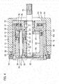
- the linear motion mechanism 3 includes the above-mentioned rotary shaft 12, to which the rotation of the electric motor 1 (see Fig. 1 ) is transmitted through the reduction gear mechanism 2 (see Fig. 1 ); a cylindrical outer ring member 14 arranged coaxially with the rotary shaft 12 so as to surround the rotary shaft 12; a plurality of planetary rollers 15 arranged between the outer periphery of the rotary shaft 12 and the inner periphery of the outer ring member 14 so as to be circumferentially spaced apart from each other; and a carrier 16 retaining the planetary rollers 15 such that the planetary rollers 15 can rotate about their respective axes while revolving around the rotary shaft 12.
- the carrier 16 includes a pair of disks 20 and 21 axially opposed to each other through the planetary rollers 15; coupling portions 22 through which the disks 20 and 21 are coupled together; and roller shafts 17 mounted to the centers of the respective planetary rollers 15, and supporting the respective planetary rollers 15 such that the planetary rollers 15 are rotatable about their axes.
- the disks 20 and 21 are annularly shaped such that the rotary shaft 12 extends through the disks 20 and 21.
- Sliding bearings 23 are mounted on the inner peripheries of the respective disks 20 and 21, along which the rotary shaft 12 extends, and are kept in sliding contact with the outer periphery of the rotary shaft 12.
- Each of the disks 20 and 21 has radially elongated insertion holes 35 through which the respective roller shafts 17 are inserted such that each roller shaft 17 is movable until the roller shaft 17 abuts against the ends of the corresponding insertion holes 35 of the disks 20 and 21.
- the roller shafts 17 are inwardly biased by radially elastically deformable elastic rings 36 each wrapped around the respective ends of the roller shafts 17.
- each planetary roller 15 is also inwardly biased through sliding bearings 37 mounted between the roller shaft 17 and the planetary roller 15, and thus is kept in rolling contact with the outer periphery of the rotary shaft 12.
- the portion of the outer periphery of the rotary shaft 15 with which the planetary rollers 15 come into contact is a cylindrical surface. Therefore, when the rotary shaft 12 rotates, the planetary rollers 15 revolve around the rotary shaft 12, inside of the outer ring member 14, while rotating about the respective roller shafts 17.
- the outer ring member 14 has, on its inner periphery, a helical rib 18 having a predetermined lead angle, i.e., extending obliquely with respect to the circumferential direction.
- Each planetary roller 15 includes, in its outer periphery, a plurality of axially spaced apart circumferential grooves 19 in which the helical rib 18 is engaged. Instead of such circumferential grooves 19, i.e., grooves having a 0 degree lead angle, each planetary roller 15 may have a helical groove having a lead angle different from that of the helical rib 18.
- a thrust bearing 25 is mounted between each planetary roller 15 and the disk 21 so as to support the planetary roller 15 such that the planetary roller 15 is rotatable about its axis.
- An aligning seat 26 is mounted between each thrust bearing 25 and the disk 21 so as to support the corresponding planetary roller 15 through the thrust bearing 25 such that the planetary roller 15 is inclinable.
- Each aligning seat 26 comprises a pressure applying seat plate 27 provided with a convex spherical surface having a center on the center axis of the corresponding roller shaft 17; and a pressure receiving seat plate 28 provided with a concave surface slidably supporting the convex spherical surface of the pressure applying seat plate 27.
- a bearing supporting member 30 having a circular annular shape is mounted inside of the linear motion mechanism housing 4, on the side of the outer ring member 14 opposite from, i.e., remoter from the brake disk 6.
- Radial bearings 31 are mounted on the inner periphery of the bearing supporting member 30 so as to rotatably support the rotary shaft 12.
- Mounted between the bearing supporting member 30 and the carrier 16 are a spacer 32 configured to revolve around the rotary shaft 12 together with the carrier 16; and a thrust bearing 33 supporting the carrier 16 through the spacer 32 such that the carrier 16 can revolve around the rotary shaft 12.
- a seal cover 34 is mounted to the open end of the outer ring member 14 closer to the brake disk 6 (see Fig. 1 ) so as to close this open end, thereby preventing foreign matter from entering the outer ring member 14.
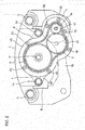
- the reduction gear mechanism 2 includes an input gear 40 to which the rotation of the motor shaft 1a of the electric motor 1 is input; an output gear 41 from which the rotation is output to the linear motion mechanism 3; and an intermediate gear 42 through which the rotation input to the input gear 40 is transmitted to the output shaft 41.
- the output gear 41 is rotatably supported by a pair of rolling bearings 43 (see Fig. 1 ) mounted in the reduction gear mechanism housing 5.
- the input and intermediate gears 40 and 42 are also rotatably supported by rolling bearings (not shown) mounted in the reduction gear mechanism housing 5
- the output gear 41 is fitted on the outer periphery of the rotary shaft 12 by spline fitting so that the rotation transmitted to the output gear 41 is transmitted to the rotary shaft 12 through the output gear 41.
- the reduction gear mechanism housing 5 comprises a side plate 44 supported by the housing-fixing plate 7B of the caliper body 7; and a lid plate 45 defining, between the side plate 44 and the lid plate 45, a space in which the gears 40, 41 and 42 of the reduction gear mechanism 2 (see Fig. 2 ) are received.
- the reduction gear mechanism housing 5 receives the reduction gear mechanism 2 as a single assembly with the components (gears 40, 41, 42) of the reduction gear mechanism 2 assembled together, and can be attached to and detached from the caliper body 7 in this state. Namely, the reduction gear mechanism 2 can be detached from the caliper body 7 with the intermediate gear 42 kept in mesh with the input gear 40 and the output gear 42.
- One of the two rolling bearings 43, which support the output gear 41, is mounted to the side plate 44, and the other rolling bearing 43 is mounted to the lid plate 45.
- the side plate 44 and the lid plate 45 are coupled together by a bolt 46.
- the side plate 44 is formed with a hole 47 through which the rotary shaft 12 is inserted.
- the linear motion mechanism housing 4 receives the linear motion mechanism 3 as a single assembly with the components of the linear motion mechanism 3 assembled together, and can be attached to and detached from the caliper body 7 (see Fig. 1 ) in this state. Namely, the linear motion mechanism 3 can de detached from the caliper body 7 with the components of the linear motion mechanism 3 assembled together.
- the linear motion mechanism housing 4 includes a tubular receiving portion 50 in which the outer ring member 14 is axially slidably received; and an end plate 51 arranged at one end of the tubular receiving portion 50.
- the tubular receiving portion 50 has, on its inner periphery, a cylindrical sliding surface 52 axially slidably supporting the outer ring member 14.
- the end plate 51 is formed with a hole 53 through which the rotary shaft 12 is inserted.
- the end plate 51 axially supports the bearing supporting member 30, and restricts the movement of the bearing supporting member 30 in the direction away from the brake disk 6 (see Fig. 1 ).
- the linear motion mechanism housing 4 and the reduction gear mechanism housing 5 are arranged on the respective opposite sides of the housing-fixing plate 7B such that the housing-fixing plate 7B is sandwiched between the housings 4 and 5.
- the linear motion mechanism housing 4 is detachably fixed to the housing-fixing plate 7B by bolts 54 (see Figs. 2 , 5 , and 6 ).
- the reduction gear mechanism housing 5 is detachably fixed to the housing-fixing plate 7B by bolts 55, which are different bolts from the bolts 54.
- the electric motor 1 is fixed to the reduction gear mechanism housing 5 by bolts 56.
- the motor shaft 1a of the electric motor 1 is inserted in and coupled to the input gear 40 of the reduction gear mechanism 2.
- a circular annular step 57 concentric with the rotary shaft 12 is formed on the contact surface of the linear motion mechanism housing 4 kept in contact with the housing-fixing plate 7B.
- the step 57 is fitted on the inner periphery of the shaft inserting hole 13 of the housing-fixing plate 7B, thereby positioning the linear motion mechanism housing 4 with respect to the housing-fixing plate 7B such that the center of the rotary shaft 12 coincides with the center of the output gear 41.
- the step 57 of the linear motion mechanism housing 4 and the shaft inserting hole 13 of the housing-fixing plate 7B constitute first positioning fitted portions fitted to each other such that the center of the rotary shaft 12 coincides with the center of the output gear 41.
- a circular annular step 58 concentric with the output shaft 41 is formed on the contact surface of the reduction gear mechanism housing 5 kept in contact with the housing-fixing plate 7B.
- the step 58 is fitted on the inner periphery of the shaft inserting hole 13 of the housing-fixing plate 7B, thereby positioning the reduction gear mechanism housing 5 with respect to the housing-fixing plate 7B such that the center of the rotary shaft 12 coincides with the center of the output gear 41.
- the step 58 of the reduction gear mechanism housing 5 and the shaft inserting hole 13 of the housing-fixing plate 7B constitute second positioning fitted portions fitted to each other such that the center of the rotary shaft 12 coincides with the center of the output gear 41.
- a seal member 59 is arranged between the linear motion mechanism housing 4 and the housing-fixing plate 7B, and is fitted in a seal groove 60 formed in the housing-fixing plate 7B, thereby preventing foreign matter from entering the linear motion mechanism housing 4.
- the seal member 59 is, e.g., an O-ring made of rubber, and having a round cross section.
- the seal groove 60 is a circular annular groove formed in the contact surface of the housing-fixing plate 7B kept in contact with the linear motion mechanism housing 4 so as to surround the shaft inserting hole 13.
- the seal member 59 separates the portion of the interface between the linear motion mechanism housing 4 and the housing-fixing plate 7B located radially inwardly of the seal member 59, from the portion of the interface located radially outwardly of the seal member 59, thereby preventing the entry of foreign matter from between the linear motion mechanism housing 4 and the housing-fixing plate 7B, and thus to provide waterproofness and dust-proofness to the electromechanical brake system.
- the circular annular seal groove 60 may be formed in the contact surface of the linear motion mechanism housing 4 kept in contact with the housing-fixing plate 7B so as to surround the shaft inserting hole 13.
- a boot 61 is mounted to the end of the linear motion mechanism housing 4 closer to the brake disk 6 so as to prevent foreign matter from entering the linear motion mechanism housing 4.
- the boot 61 is a tubular member folded like a bellows so as to be stretchable in the axial direction.
- One end of the boot 61 is connected to a groove 62 formed in the inner periphery of the linear motion mechanism housing 4, and the other end of the boot 61 is connected to a groove 63 formed in the outer periphery of the outer ring member 14.
- An engagement protrusion 64 is formed on the surface of the friction pad 9 on its back side, while an engagement recess 65 is formed in the end of the outer ring member 14 closer to the brake disk 6 such that the engagement protrusion 64 is engaged in the engagement recess 65, thereby rotationally fixing the outer member 14.
- the linear motion mechanism housing 4 has a rotationally symmetrical shape such that its cross-sectional view remains the same even after rotated about the rotary shaft 12 by 180 degrees.
- the linear motion mechanism housing 4 may have a rotationally symmetrical shape such that its cross-sectional view remains the same when rotated about the rotary shaft 12 by 120 degrees or 90 degrees.
- the linear motion mechanism 3 pushes the friction pad 9 against the brake disk 6, the axial reaction force applied to the linear motion mechanism 3 is received by the housing-fixing plate 7B through the linear motion mechanism housing 4 (see Fig. 1 ), and the axial reaction force which the housing-fixing plate 7 receives at this time might deform the outer shell portion 7C.
- the outer shell portion 7C is designed such that the thickness of the portion of the outer shell portion 7C opposed to the linear motion mechanism housing 4 gradually increases from the circumferential center of this opposed portion toward both sides thereof, thereby increasing the flexural rigidity of the outer shell portion 7C. Also, by designing the outer shell portion 7C in this way, it is possible to increase not only the flexural rigidity of the outer shell portion 7C but also the rigidity of the housing-fixing plate 7B, which is connected to the outer shell portion 7C.
- the linear motion mechanism housing 4 is made of a material different from the material of the caliper body 7.
- the caliper body 7 is made of cast iron
- the linear motion mechanism housing 4 is made of an aluminum alloy, which is more lightweight than cast iron.
- the linear motion mechanism 3 converts the rotation transmitted from the electric motor 1 to the linear motion of the outer ring member 14; moves the friction pad 9 together with the outer ring member 14; and presses the friction pad 9 against the brake disk 6, thereby generating a braking force.
- the linear motion mechanism 3 is received in the linear motion mechanism housing 4 with the components of the linear motion mechanism 3 assembled together, when the linear motion mechanism 3 needs to be detached from the caliper body 7 for maintenance, by removing the bolts 54, and detaching the linear motion mechanism housing 4 from the housing-fixing plate 7B, it is possible to detach and handle the linear motion mechanism 3 as a single assembly, and thus to easily perform maintenance.
- the housing-fixing plate 7B to which the linear motion mechanism housing 4 is detachably fixed, is arranged on the side of the linear motion mechanism housing 4 remoter from the brake disk 6, the housing-fixing plate 7B, which is a part of the caliper body 7, can receive the axial reaction force applied to the linear motion mechanism 3 when the liner motion mechanism 3 presses the friction pad 9 against the brake disk 6.
- the electromechanical brake system of the present invention is rigid enough to receive the axial reaction force applied to the linear motion mechanism 3 when the linear motion mechanism 3 presses the friction pad 9 against the bake disk 6, and also, the linear motion mechanism 3 can be detached as a single assembly. In this way, the electromechanical brake system is axially rigid, and also enables easy maintenance.
- the reduction gear mechanism 2 since the reduction gear mechanism 2 is received in the reduction gear mechanism housing 5 with the components of the reduction gear mechanism 2 assembled together, when the reduction gear mechanism 2 needs to be detached from the caliper body 7 for maintenance, by removing the bolts 55, and detaching the reduction gear mechanism housing 5 from the housing-fixing plate 7B, it is possible to detach and handle the reduction gear mechanism 2 as a single assembly, and thus to easily perform maintenance.
- the electromechanical brake system of the present invention is configured such that the center of the rotary shaft 12 of the linear motion mechanism 3 coincides with the center of the output gear 41 of the reduction gear mechanism 2 by fitting the step 57 of the linear motion mechanism housing 4 onto the shaft inserting hole 13 of the housing-fixing plate 7B when mounting the linear motion mechanism housing 4 to the housing-fixing plate 7B, it is possible to easily mount the linear motion mechanism 3 in position, and to easily perform maintenance.
- the electromechanical brake system of the present invention is configured such that the center of the rotary shaft 12 of the linear motion mechanism 3 coincides with the center of the output gear 41 of the reduction gear mechanism 2 by fitting the step 58 of the reduction gear mechanism housing 5 onto the shaft inserting hole 13 of the housing-fixing plate 7B when mounting the reduction gear mechanism housing 5 to the housing-fixing plate 7B, it is possible to easily mount the reduction gear mechanism 2 in position, and to easily perform maintenance.
- the linear motion mechanism housing 4 has a rotationally symmetrical shape as illustrated in Fig. 3 , when mounting, to the housing-fixing plate 7B, the linear motion mechanism housing 4, in which the linear motion mechanism 3 is received as a single assembly with the components of the linear motion mechanism 3 assembled together, it is not necessary to pay attention to the angular position of the linear motion mechanism housing 4. Therefore, it is possible to eliminate the risk that the linear motion mechanism 3 as a single assembly might be mounted in a wrong angular position.
- the sliding surface 52 for sliding the outer ring member 14 is formed on the linear motion mechanism housing 4, which can be detached from the caliper body 7, it is possible to easily form the sliding surface 52.
- the electromechanical brake system of the present invention is configured such that, with the linear motion mechanism 3 received in the linear motion mechanism housing 4, the linear motion mechanism housing 4 can be mounted to the caliper body 7 from radially inwardly of the brake disk 6, it is possible to design the shape of the claw portion 7A relatively freely, unlike the electromechanical brake system illustrated in Fig. 5 of Japanese Unexamined Patent Application Publication No. 2007-037305 , in which the shape of the claw portion is limited. (That is, in this publication, since the linear motion mechanism has to be axially inserted from the side of the brake system where there is the claw portion, the claw portion has to be designed and shaped to prevent interference of the linear motion mechanism with the claw portion when the former is axially inserted into the caliper body.)
- the bolts 54 may be each any kind of bolt. While, in Figs. 2 , 5 and 6 , the bolts 54 are inserted through respective through holes formed in the housing-fixing plate 7B such that the threaded portions of the bolts 54 are engaged in respective threaded holes formed in the linear motion mechanism housing 4, the insertion direction of the bolts 54 may be inverted. Namely, the bolts 54 may be inserted through respective through holes formed in the linear motion mechanism housing 4 from the side of the linear motion mechanism housing 4 closer to the claw portion 7 such that the threaded portions of the bolts 54 are engaged in respective threaded holes formed in the housing-fixing plate 7B.
- the bolts 54 used for fixing the linear motion mechanism housing 4 to the housing-fixing plate 7B are different bolts from the bolts 55 used for fixing the reduction gear mechanism housing 5 to the housing-fixing plate 7B
- only the bolts 54 may be used for fixing both the linear motion mechanism housing 4 and the reduction gear mechanism housing 5 to the housing-fixing plate 7B as illustrated in Fig. 7 .
- the linear motion mechanism housing 4 and the reduction gear mechanism housing 5 may be detachably tightened relative to each other by common tightening components (bolts 54), and fixed to the housing-fixing plate 7B. If these housings 4 and 5 are fixed in this way, when the linear motion mechanism housing 4 is detached from the housing-fixing plate 7B, the reduction gear mechanism housing 5 is also simultaneously detached from the housing-fixing plate 7B, thus enabling easier maintenance.
- the housing of the electric motor 1 is provided separately from the reduction gear mechanism housing 5, the former housing may be integral with the latter housing 5.
- rolling bearings 43 are mounted to the reduction gear mechanism 5 so as to rotatably support the output gear 41
- the rolling bearings 43 may be dispensed with so that the output gear 41 is supported by only the rotary shaft 12 as illustrated in Fig. 8 .
- the diameter of the shaft inserting hole 13 of the housing-fixing plate 7B, and the diameter of the hole 47 in the side plate 44 of the reduction gear mechanism housing 5 to be each larger than the outer diameter of the output gear 41, it is possible to attach and detach the linear motion mechanism 3 and the output gear 41 as a single assembly.
- the output gear 41 and the intermediate gear 42 are positioned relative to each other such that the backlash (clearance) between the output and intermediate gears 41 and 42 is kept at an appropriate size.
- the linear motion mechanism 3 is a planetary roller mechanism in which the outer ring member 14 axially moves when the planetary rollers 15 revolve around the rotary shaft 12
- the linear motion mechanism 3 may be a planetary roller mechanism in which the carrier 16 axially moves when the planetary rollers 15 revolve around the rotary shaft 12.
Landscapes
- Engineering & Computer Science (AREA)
- General Engineering & Computer Science (AREA)
- Mechanical Engineering (AREA)
- Transportation (AREA)
- Braking Arrangements (AREA)
- Braking Systems And Boosters (AREA)
Claims (10)
- Système de frein électromécanique, comprenant :un moteur électrique (1) ;deux plaquettes de friction (8 et 9) opposées axialement entre elles via un disque de frein (6) ;un mécanisme de déplacement linéaire (3) configuré pour convertir la rotation transmise par le moteur électrique (1) en un déplacement linéaire, poussant ainsi une plaquette (9) des deux plaquettes de friction (8 et 9) contre le disque de frein (6) ;un boîtier (4) du mécanisme de déplacement linéaire dans lequel le mécanisme de déplacement linéaire (3) est logé comme un assemblage unique avec des composants du mécanisme de déplacement linéaire (3) assemblés entre eux ; etun corps d'étrier (7) formé pour s'étendre sur la périphérie externe du disque de frein (6) ;dans lequel le corps d'étrier (7) comprend :une portion de griffe (7A) supportant axialement l'autre plaquette (8) des deux plaquettes de friction (8 et 9) ;une plaque de fixation de boîtier (7B) qui est disposée sur l'un des deux côtés du boîtier (4) du mécanisme de déplacement linéaire qui est à l'opposé du disque de frein (6), et à laquelle le boîtier (4) du mécanisme de déplacement linéaire est fixé de manière détachable ; etune portion de coque externe (7C) qui est située radialement vers l'extérieur du disque de frein (6), et à travers laquelle la portion de griffe (7A) et la plaque de fixation de boîtier (7B) sont couplées entre elles.
- Système de frein électromécanique selon la revendication 1, comprenant en outre
un mécanisme à engrenage de réduction (2) configuré de telle sorte que la vitesse de rotation du moteur électrique (1) est réduite et transmise au mécanisme de déplacement linéaire (3) par le mécanisme à engrenage de réduction (2) ; et
un boîtier (5) de mécanisme à engrenage de réduction dans lequel le mécanisme à engrenage de réduction (2) est reçu comme un assemblage unique avec des composants du mécanisme à engrenage de réduction (2) assemblés entre eux, et qui est fixé de manière détachable à la plaque de fixation de boîtier (7B). - Système de frein électromécanique selon la revendication 2, dans lequel le mécanisme à engrenage de réduction (2) comprend un engrenage de sortie (41) configuré pour sortir la rotation du moteur électrique (1) sur le mécanisme de déplacement linéaire (3),
dans lequel le mécanisme de déplacement linéaire (3) comprend un arbre rotatif (12) agencé coaxialement avec l'engrenage de sortie (41) de telle sorte que la rotation du moteur électrique (1) est entrée sur l'arbre rotatif (12) depuis l'engrenage de sortie (41), et
dans lequel le système de frein électromécanique comprend en outre de premières portions ajustées de positionnement (13 et 57) agencées entre des surfaces de contact du boîtier (4) de mécanisme de déplacement linéaire et de la plaque de fixation de boîtier (7B) qui sont en contact entre elles, et ajustées entre elles de telle sorte que le centre de l'arbre rotatif (12) coïncide avec le centre de l'engrenage de sortie (41). - Système de frein électromécanique selon la revendication 3, comprenant en outre des deuxièmes portions ajustées de positionnement (13 et 58) agencées entre des surfaces de contact du boîtier de mécanisme à engrenage de réduction (5) et de la plaque de fixation de boîtier (7B) qui sont en contact entre elles, et ajustées entre elles de telle sorte que le centre de l'arbre rotatif (12) coïncide avec le centre de l'engrenage de sortie (41).
- Système de frein électromécanique selon l'une quelconque des revendications 2 à 4,
dans lequel le boîtier (4) du mécanisme de déplacement linéaire et le boîtier (5) du mécanisme à engrenage de réduction sont agencés de telle sorte que la plaque de fixation de boîtier (7B) est intercalée entre le boîtier (4) du mécanisme de déplacement linéaire et le boîtier (5) du mécanisme à engrenage de réduction, et
dans lequel le boîtier (4) du mécanisme de déplacement linéaire et le boîtier (5) du mécanisme à engrenage de réduction sont serrés de manière détachable entre eux par un composant de serrage (54), et fixés à la plaque de fixation de boîtier (7B). - Système de frein électromécanique selon l'une quelconque des revendications 1 à 5, dans lequel le mécanisme de déplacement linéaire (3) comprend en outre
un élément de mouvement linéaire (14) configuré pour se déplacer conjointement à ladite plaquette (9) desdites deux plaquettes de friction (8 et 9) ; et
un soufflet tubulaire étirable (61) comportant deux extrémités, l'une des deux extrémités étant connectée à une périphérie interne du boîtier (4) du mécanisme de déplacement linéaire, et l'autre desdites deux extrémités étant connectée à une périphérie externe de l'élément de mouvement linéaire (14), de manière à éviter que des corps étrangers n'entrent dans le boîtier (4) du mécanisme de déplacement linéaire. - Système de frein électromécanique selon l'une quelconque des revendications 1 à 6, comprenant en outre un élément d'étanchéité (59) agencé entre le boîtier (4) du mécanisme de déplacement linéaire et la plaque de fixation de boîtier (7B) de manière à éviter que des corps étrangers n'entrent dans le boîtier (4) du mécanisme de déplacement linéaire.
- Système de frein électromécanique selon l'une quelconque des revendications 1 à 7, dans lequel le boîtier (4) du mécanisme de déplacement linéaire est constitué d'un matériau différent du matériau du corps d'étrier (7).
- Système de frein électromécanique selon l'une quelconque des revendications 1 à 8, dans lequel le boîtier (4) du mécanisme de déplacement linéaire présente une forme symétrique en rotation.
- Système de frein électromécanique selon l'une quelconque des revendications 1 à 9, dans lequel le mécanisme de déplacement linéaire (3) est un mécanisme de rouleau planétaire comprenant :un élément annulaire externe (14) ;des rouleaux planétaires (15) configurés de telle sorte que, du fait de la rotation du moteur électrique (1), les rouleaux planétaires (15) tournent autour de l'arbre rotatif (12) à l'intérieur de l'élément annulaire externe (14), tout en tournant autour d'axes respectifs des rouleaux planétaires (16) ;une nervure hélicoïdale (18) sur une périphérie interne de l'élément annulaire externe (14) ; etune rainure hélicoïdale ou des rainures circonférentielles (19) agencées dans une périphérie externe de chacun des rouleaux planétaires (15) de telle sorte que la nervure hélicoïdale (18) est engagée dans la rainure hélicoïdale ou dans les rainures circonférentielles (19) .
Applications Claiming Priority (2)
| Application Number | Priority Date | Filing Date | Title |
|---|---|---|---|
| JP2015154264A JP6579853B2 (ja) | 2015-08-04 | 2015-08-04 | 電動ブレーキ装置 |
| PCT/JP2016/071979 WO2017022586A1 (fr) | 2015-08-04 | 2016-07-27 | Dispositif de freinage électrique |
Publications (3)
| Publication Number | Publication Date |
|---|---|
| EP3333441A1 EP3333441A1 (fr) | 2018-06-13 |
| EP3333441A4 EP3333441A4 (fr) | 2018-08-22 |
| EP3333441B1 true EP3333441B1 (fr) | 2020-11-18 |
Family
ID=57943027
Family Applications (1)
| Application Number | Title | Priority Date | Filing Date |
|---|---|---|---|
| EP16832865.6A Active EP3333441B1 (fr) | 2015-08-04 | 2016-07-27 | Dispositif de freinage électrique |
Country Status (5)
| Country | Link |
|---|---|
| US (1) | US10882503B2 (fr) |
| EP (1) | EP3333441B1 (fr) |
| JP (1) | JP6579853B2 (fr) |
| CN (1) | CN107923455B (fr) |
| WO (1) | WO2017022586A1 (fr) |
Families Citing this family (8)
| Publication number | Priority date | Publication date | Assignee | Title |
|---|---|---|---|---|
| JP6579853B2 (ja) * | 2015-08-04 | 2019-09-25 | Ntn株式会社 | 電動ブレーキ装置 |
| KR102856119B1 (ko) * | 2020-06-22 | 2025-09-04 | 현대모비스 주식회사 | 전동식 브레이크 조립구조 |
| JP7583554B2 (ja) * | 2020-08-27 | 2024-11-14 | 日立Astemo上田株式会社 | 液圧発生装置 |
| CN113669383B (zh) * | 2021-08-18 | 2023-05-26 | 佗道医疗科技有限公司 | 一种运动关节制动器及摆转机构 |
| DE102022119400A1 (de) | 2021-11-17 | 2023-05-17 | Zf Active Safety Gmbh | Kugelgewindetrieb für eine Aktorbaugruppe, Aktorbaugruppe und Verfahren zum Herstellen eines Kugelgewindetriebs |
| DE102022119397A1 (de) | 2021-11-17 | 2023-05-17 | Zf Active Safety Gmbh | Fahrzeugbremsenaktor und elektromechanische Bremse |
| DE102022202364A1 (de) | 2022-03-09 | 2023-09-14 | Continental Automotive Technologies GmbH | Elektromechanisch betätigte Radbremse für ein Kraftfahrzeug und Rotations-Translations-Getriebeanordnung |
| JP7815067B2 (ja) * | 2022-09-05 | 2026-02-17 | 曙ブレーキ工業株式会社 | ディスクブレーキ装置及びその組立方法 |
Family Cites Families (27)
| Publication number | Priority date | Publication date | Assignee | Title |
|---|---|---|---|---|
| US4194596A (en) * | 1978-12-29 | 1980-03-25 | Eaton Corporation | Disc brake housing assembly |
| US4526053A (en) * | 1983-02-14 | 1985-07-02 | Millipore Corporation | Stabilized apparatus for converting rotational motion to linear motion |
| DE19627646C2 (de) * | 1996-07-09 | 1999-11-25 | Lucas Ind Plc | Aktuatorenbaugruppe für eine Fahrzeugbremse und Fahrzeugbremse mit einer derartigen Aktuatorenbaugruppe |
| DE19740867A1 (de) * | 1997-09-16 | 1999-03-18 | Itt Mfg Enterprises Inc | Elektromechanisch betätigbare Scheibenbremse |
| NL1007296C2 (nl) * | 1997-10-16 | 1999-04-19 | Skf Ind Trading & Dev | Modulaire actuator, alsmede remklauw met een dergelijke actuator. |
| JP2002510020A (ja) * | 1998-01-20 | 2002-04-02 | エスケイエフ エンジニアリング アンド リサーチ センター ビーブイ | モジュール式アクチュエータおよびアクチュエータを備えるブレーキキャリパ |
| NL1009584C2 (nl) * | 1998-07-07 | 2000-01-10 | Skf Eng & Res Centre Bv | Actuator voorzien van een centrale steun, alsmede remklauw met een dergelijke actuator. |
| JP3736225B2 (ja) | 1999-09-14 | 2006-01-18 | 日産自動車株式会社 | 電動ブレーキ装置 |
| JP2003529027A (ja) * | 2000-03-27 | 2003-09-30 | コンティネンタル・テーベス・アクチエンゲゼルシヤフト・ウント・コンパニー・オッフェネ・ハンデルスゲゼルシヤフト | ねじ伝動装置、遊星歯車装置およびこれらによって影響を受ける操作要素を備えた操作ユニット |
| JP2002161933A (ja) * | 2000-11-24 | 2002-06-07 | Ntn Corp | 駐車ブレーキ用すべり軸受 |
| DE10146779A1 (de) * | 2001-09-22 | 2003-04-17 | Bosch Gmbh Robert | Elektromechanische Bremse |
| WO2005124180A1 (fr) * | 2004-06-15 | 2005-12-29 | Pbr Australia Pty Ltd | Mecanisme d'actionnement et ensemble frein |
| JP4786240B2 (ja) | 2005-07-27 | 2011-10-05 | Ntn株式会社 | 電動式直動アクチュエータおよび電動式ブレーキ装置 |
| JP4988280B2 (ja) * | 2006-09-21 | 2012-08-01 | Ntn株式会社 | 電動式直動アクチュエータおよび電動式ブレーキ装置 |
| JP2009174585A (ja) * | 2008-01-22 | 2009-08-06 | Ntn Corp | 電動式直動アクチュエータおよび電動式ブレーキ装置 |
| KR20100039072A (ko) * | 2008-10-07 | 2010-04-15 | 주식회사 만도 | 전자식 주차 브레이크 시스템을 갖춘 디스크 브레이크 |
| KR101327360B1 (ko) * | 2008-10-08 | 2013-11-11 | 주식회사 만도 | 차량용 디스크 브레이크 |
| KR101126176B1 (ko) * | 2010-05-12 | 2012-03-26 | 주식회사 만도 | 전동식 디스크 브레이크 |
| KR101220405B1 (ko) * | 2010-09-07 | 2013-01-09 | 주식회사 만도 | 전동식 디스크 브레이크 장치 |
| JP5077604B2 (ja) * | 2010-12-28 | 2012-11-21 | 日立オートモティブシステムズ株式会社 | 電動ディスクブレーキ |
| CN107420467A (zh) * | 2011-01-14 | 2017-12-01 | 喜达迪有限公司 | 制动活塞和活塞鼻部 |
| JP5596575B2 (ja) | 2011-01-21 | 2014-09-24 | Ntn株式会社 | 電動式直動アクチュエータおよび電動式ディスクブレーキ装置 |
| DE102012216588A1 (de) * | 2012-09-17 | 2014-03-20 | Continental Teves Ag & Co. Ohg | Kombinierte Fahrzeugbremse |
| KR20140103431A (ko) * | 2013-02-18 | 2014-08-27 | 주식회사 만도 | 볼 램프 구조를 이용한 모터 브레이크 |
| JP6335443B2 (ja) * | 2013-06-13 | 2018-05-30 | Ntn株式会社 | 電動式ブレーキ装置 |
| US20150001010A1 (en) | 2013-06-26 | 2015-01-01 | Chih-Hsien Liao | Electric parking caliper |
| JP6579853B2 (ja) * | 2015-08-04 | 2019-09-25 | Ntn株式会社 | 電動ブレーキ装置 |
-
2015
- 2015-08-04 JP JP2015154264A patent/JP6579853B2/ja active Active
-
2016
- 2016-07-27 EP EP16832865.6A patent/EP3333441B1/fr active Active
- 2016-07-27 US US15/748,897 patent/US10882503B2/en active Active
- 2016-07-27 WO PCT/JP2016/071979 patent/WO2017022586A1/fr not_active Ceased
- 2016-07-27 CN CN201680045587.5A patent/CN107923455B/zh not_active Expired - Fee Related
Non-Patent Citations (1)
| Title |
|---|
| None * |
Also Published As
| Publication number | Publication date |
|---|---|
| JP2017032101A (ja) | 2017-02-09 |
| WO2017022586A1 (fr) | 2017-02-09 |
| CN107923455B (zh) | 2020-04-24 |
| JP6579853B2 (ja) | 2019-09-25 |
| CN107923455A (zh) | 2018-04-17 |
| EP3333441A4 (fr) | 2018-08-22 |
| US10882503B2 (en) | 2021-01-05 |
| EP3333441A1 (fr) | 2018-06-13 |
| US20180273010A1 (en) | 2018-09-27 |
Similar Documents
| Publication | Publication Date | Title |
|---|---|---|
| US10882503B2 (en) | Electromechanical brake system | |
| US10167929B2 (en) | Speed reducer and actuator | |
| US8220594B2 (en) | Electric brake device | |
| EP3009705B1 (fr) | Actionneur électrique à mouvement linéaire et système de frein électrique | |
| US10228034B2 (en) | Electric linear motion actuator and electric disk brake system | |
| JP6659364B2 (ja) | 電動ブレーキ装置 | |
| US10508722B2 (en) | Electric linear motion actuator and electromechanical brake system | |
| US20110253508A1 (en) | Roller assembly, roller unit, and conveyor apparatus | |
| CN103348163A (zh) | 电动式直动致动器以及电动式盘式制动装置 | |
| EP3415784B1 (fr) | Dispositif de frein électrique | |
| CN101389873B (zh) | 行星辊式减速机 | |
| EP2889504B1 (fr) | Mécanisme irréversible | |
| EP2835556A1 (fr) | Dispositif de frein à friction | |
| US12049944B2 (en) | Planetary roller screw drive | |
| EP3045774B1 (fr) | Actionneur linéaire électrique et dispositif de freinage électrique | |
| EP2835554B1 (fr) | Dispositif de frein à friction | |
| CN109572908A (zh) | 制动装置 | |
| EP3564640B1 (fr) | Capteur de charge et système de freinage électromécanique | |
| JP6719916B2 (ja) | 電動ブレーキ装置および電動ブレーキ装置の製造方法 | |
| JP7152913B2 (ja) | 電動式直動アクチュエータ及び電動ブレーキ装置 | |
| JP6881040B2 (ja) | ギヤの支持構造 | |
| WO2017104704A1 (fr) | Unité d'embrayage | |
| JPH09217759A (ja) | 自動変速機の油圧サーボ装置 |
Legal Events
| Date | Code | Title | Description |
|---|---|---|---|
| STAA | Information on the status of an ep patent application or granted ep patent |
Free format text: STATUS: THE INTERNATIONAL PUBLICATION HAS BEEN MADE |
|
| PUAI | Public reference made under article 153(3) epc to a published international application that has entered the european phase |
Free format text: ORIGINAL CODE: 0009012 |
|
| STAA | Information on the status of an ep patent application or granted ep patent |
Free format text: STATUS: REQUEST FOR EXAMINATION WAS MADE |
|
| 17P | Request for examination filed |
Effective date: 20180228 |
|
| AK | Designated contracting states |
Kind code of ref document: A1 Designated state(s): AL AT BE BG CH CY CZ DE DK EE ES FI FR GB GR HR HU IE IS IT LI LT LU LV MC MK MT NL NO PL PT RO RS SE SI SK SM TR |
|
| AX | Request for extension of the european patent |
Extension state: BA ME |
|
| A4 | Supplementary search report drawn up and despatched |
Effective date: 20180720 |
|
| RIC1 | Information provided on ipc code assigned before grant |
Ipc: F16D 65/02 20060101ALI20180716BHEP Ipc: F16D 125/50 20120101ALI20180716BHEP Ipc: F16D 65/18 20060101ALI20180716BHEP Ipc: F16D 121/24 20120101ALI20180716BHEP Ipc: F16D 125/48 20120101ALI20180716BHEP Ipc: F16D 55/226 20060101AFI20180716BHEP Ipc: F16D 65/00 20060101ALI20180716BHEP Ipc: F16D 125/40 20120101ALI20180716BHEP Ipc: B60T 13/74 20060101ALI20180716BHEP Ipc: F16D 125/06 20120101ALI20180716BHEP Ipc: F16D 125/08 20120101ALI20180716BHEP |
|
| DAV | Request for validation of the european patent (deleted) | ||
| DAX | Request for extension of the european patent (deleted) | ||
| GRAP | Despatch of communication of intention to grant a patent |
Free format text: ORIGINAL CODE: EPIDOSNIGR1 |
|
| STAA | Information on the status of an ep patent application or granted ep patent |
Free format text: STATUS: GRANT OF PATENT IS INTENDED |
|
| INTG | Intention to grant announced |
Effective date: 20200629 |
|
| GRAS | Grant fee paid |
Free format text: ORIGINAL CODE: EPIDOSNIGR3 |
|
| GRAA | (expected) grant |
Free format text: ORIGINAL CODE: 0009210 |
|
| STAA | Information on the status of an ep patent application or granted ep patent |
Free format text: STATUS: THE PATENT HAS BEEN GRANTED |
|
| AK | Designated contracting states |
Kind code of ref document: B1 Designated state(s): AL AT BE BG CH CY CZ DE DK EE ES FI FR GB GR HR HU IE IS IT LI LT LU LV MC MK MT NL NO PL PT RO RS SE SI SK SM TR |
|
| REG | Reference to a national code |
Ref country code: GB Ref legal event code: FG4D |
|
| REG | Reference to a national code |
Ref country code: CH Ref legal event code: EP |
|
| REG | Reference to a national code |
Ref country code: IE Ref legal event code: FG4D |
|
| REG | Reference to a national code |
Ref country code: DE Ref legal event code: R096 Ref document number: 602016048265 Country of ref document: DE |
|
| REG | Reference to a national code |
Ref country code: AT Ref legal event code: REF Ref document number: 1336109 Country of ref document: AT Kind code of ref document: T Effective date: 20201215 |
|
| REG | Reference to a national code |
Ref country code: AT Ref legal event code: MK05 Ref document number: 1336109 Country of ref document: AT Kind code of ref document: T Effective date: 20201118 |
|
| REG | Reference to a national code |
Ref country code: NL Ref legal event code: MP Effective date: 20201118 |
|
| PG25 | Lapsed in a contracting state [announced via postgrant information from national office to epo] |
Ref country code: RS Free format text: LAPSE BECAUSE OF FAILURE TO SUBMIT A TRANSLATION OF THE DESCRIPTION OR TO PAY THE FEE WITHIN THE PRESCRIBED TIME-LIMIT Effective date: 20201118 Ref country code: PT Free format text: LAPSE BECAUSE OF FAILURE TO SUBMIT A TRANSLATION OF THE DESCRIPTION OR TO PAY THE FEE WITHIN THE PRESCRIBED TIME-LIMIT Effective date: 20210318 Ref country code: NO Free format text: LAPSE BECAUSE OF FAILURE TO SUBMIT A TRANSLATION OF THE DESCRIPTION OR TO PAY THE FEE WITHIN THE PRESCRIBED TIME-LIMIT Effective date: 20210218 Ref country code: FI Free format text: LAPSE BECAUSE OF FAILURE TO SUBMIT A TRANSLATION OF THE DESCRIPTION OR TO PAY THE FEE WITHIN THE PRESCRIBED TIME-LIMIT Effective date: 20201118 Ref country code: GR Free format text: LAPSE BECAUSE OF FAILURE TO SUBMIT A TRANSLATION OF THE DESCRIPTION OR TO PAY THE FEE WITHIN THE PRESCRIBED TIME-LIMIT Effective date: 20210219 |
|
| PG25 | Lapsed in a contracting state [announced via postgrant information from national office to epo] |
Ref country code: SE Free format text: LAPSE BECAUSE OF FAILURE TO SUBMIT A TRANSLATION OF THE DESCRIPTION OR TO PAY THE FEE WITHIN THE PRESCRIBED TIME-LIMIT Effective date: 20201118 Ref country code: LV Free format text: LAPSE BECAUSE OF FAILURE TO SUBMIT A TRANSLATION OF THE DESCRIPTION OR TO PAY THE FEE WITHIN THE PRESCRIBED TIME-LIMIT Effective date: 20201118 Ref country code: IS Free format text: LAPSE BECAUSE OF FAILURE TO SUBMIT A TRANSLATION OF THE DESCRIPTION OR TO PAY THE FEE WITHIN THE PRESCRIBED TIME-LIMIT Effective date: 20210318 Ref country code: PL Free format text: LAPSE BECAUSE OF FAILURE TO SUBMIT A TRANSLATION OF THE DESCRIPTION OR TO PAY THE FEE WITHIN THE PRESCRIBED TIME-LIMIT Effective date: 20201118 Ref country code: BG Free format text: LAPSE BECAUSE OF FAILURE TO SUBMIT A TRANSLATION OF THE DESCRIPTION OR TO PAY THE FEE WITHIN THE PRESCRIBED TIME-LIMIT Effective date: 20210218 Ref country code: AT Free format text: LAPSE BECAUSE OF FAILURE TO SUBMIT A TRANSLATION OF THE DESCRIPTION OR TO PAY THE FEE WITHIN THE PRESCRIBED TIME-LIMIT Effective date: 20201118 |
|
| REG | Reference to a national code |
Ref country code: LT Ref legal event code: MG9D |
|
| PG25 | Lapsed in a contracting state [announced via postgrant information from national office to epo] |
Ref country code: HR Free format text: LAPSE BECAUSE OF FAILURE TO SUBMIT A TRANSLATION OF THE DESCRIPTION OR TO PAY THE FEE WITHIN THE PRESCRIBED TIME-LIMIT Effective date: 20201118 |
|
| PG25 | Lapsed in a contracting state [announced via postgrant information from national office to epo] |
Ref country code: EE Free format text: LAPSE BECAUSE OF FAILURE TO SUBMIT A TRANSLATION OF THE DESCRIPTION OR TO PAY THE FEE WITHIN THE PRESCRIBED TIME-LIMIT Effective date: 20201118 Ref country code: CZ Free format text: LAPSE BECAUSE OF FAILURE TO SUBMIT A TRANSLATION OF THE DESCRIPTION OR TO PAY THE FEE WITHIN THE PRESCRIBED TIME-LIMIT Effective date: 20201118 Ref country code: SM Free format text: LAPSE BECAUSE OF FAILURE TO SUBMIT A TRANSLATION OF THE DESCRIPTION OR TO PAY THE FEE WITHIN THE PRESCRIBED TIME-LIMIT Effective date: 20201118 Ref country code: LT Free format text: LAPSE BECAUSE OF FAILURE TO SUBMIT A TRANSLATION OF THE DESCRIPTION OR TO PAY THE FEE WITHIN THE PRESCRIBED TIME-LIMIT Effective date: 20201118 Ref country code: RO Free format text: LAPSE BECAUSE OF FAILURE TO SUBMIT A TRANSLATION OF THE DESCRIPTION OR TO PAY THE FEE WITHIN THE PRESCRIBED TIME-LIMIT Effective date: 20201118 Ref country code: SK Free format text: LAPSE BECAUSE OF FAILURE TO SUBMIT A TRANSLATION OF THE DESCRIPTION OR TO PAY THE FEE WITHIN THE PRESCRIBED TIME-LIMIT Effective date: 20201118 |
|
| REG | Reference to a national code |
Ref country code: DE Ref legal event code: R097 Ref document number: 602016048265 Country of ref document: DE |
|
| PG25 | Lapsed in a contracting state [announced via postgrant information from national office to epo] |
Ref country code: DK Free format text: LAPSE BECAUSE OF FAILURE TO SUBMIT A TRANSLATION OF THE DESCRIPTION OR TO PAY THE FEE WITHIN THE PRESCRIBED TIME-LIMIT Effective date: 20201118 |
|
| PLBE | No opposition filed within time limit |
Free format text: ORIGINAL CODE: 0009261 |
|
| STAA | Information on the status of an ep patent application or granted ep patent |
Free format text: STATUS: NO OPPOSITION FILED WITHIN TIME LIMIT |
|
| 26N | No opposition filed |
Effective date: 20210819 |
|
| PG25 | Lapsed in a contracting state [announced via postgrant information from national office to epo] |
Ref country code: IT Free format text: LAPSE BECAUSE OF FAILURE TO SUBMIT A TRANSLATION OF THE DESCRIPTION OR TO PAY THE FEE WITHIN THE PRESCRIBED TIME-LIMIT Effective date: 20201118 Ref country code: AL Free format text: LAPSE BECAUSE OF FAILURE TO SUBMIT A TRANSLATION OF THE DESCRIPTION OR TO PAY THE FEE WITHIN THE PRESCRIBED TIME-LIMIT Effective date: 20201118 Ref country code: NL Free format text: LAPSE BECAUSE OF FAILURE TO SUBMIT A TRANSLATION OF THE DESCRIPTION OR TO PAY THE FEE WITHIN THE PRESCRIBED TIME-LIMIT Effective date: 20201118 |
|
| PG25 | Lapsed in a contracting state [announced via postgrant information from national office to epo] |
Ref country code: SI Free format text: LAPSE BECAUSE OF FAILURE TO SUBMIT A TRANSLATION OF THE DESCRIPTION OR TO PAY THE FEE WITHIN THE PRESCRIBED TIME-LIMIT Effective date: 20201118 |
|
| PG25 | Lapsed in a contracting state [announced via postgrant information from national office to epo] |
Ref country code: ES Free format text: LAPSE BECAUSE OF FAILURE TO SUBMIT A TRANSLATION OF THE DESCRIPTION OR TO PAY THE FEE WITHIN THE PRESCRIBED TIME-LIMIT Effective date: 20201118 |
|
| REG | Reference to a national code |
Ref country code: CH Ref legal event code: PL |
|
| GBPC | Gb: european patent ceased through non-payment of renewal fee |
Effective date: 20210727 |
|
| PG25 | Lapsed in a contracting state [announced via postgrant information from national office to epo] |
Ref country code: MC Free format text: LAPSE BECAUSE OF FAILURE TO SUBMIT A TRANSLATION OF THE DESCRIPTION OR TO PAY THE FEE WITHIN THE PRESCRIBED TIME-LIMIT Effective date: 20201118 |
|
| REG | Reference to a national code |
Ref country code: BE Ref legal event code: MM Effective date: 20210731 |
|
| PG25 | Lapsed in a contracting state [announced via postgrant information from national office to epo] |
Ref country code: LI Free format text: LAPSE BECAUSE OF NON-PAYMENT OF DUE FEES Effective date: 20210731 Ref country code: GB Free format text: LAPSE BECAUSE OF NON-PAYMENT OF DUE FEES Effective date: 20210727 Ref country code: CH Free format text: LAPSE BECAUSE OF NON-PAYMENT OF DUE FEES Effective date: 20210731 |
|
| PG25 | Lapsed in a contracting state [announced via postgrant information from national office to epo] |
Ref country code: IS Free format text: LAPSE BECAUSE OF FAILURE TO SUBMIT A TRANSLATION OF THE DESCRIPTION OR TO PAY THE FEE WITHIN THE PRESCRIBED TIME-LIMIT Effective date: 20210318 Ref country code: LU Free format text: LAPSE BECAUSE OF NON-PAYMENT OF DUE FEES Effective date: 20210727 |
|
| PG25 | Lapsed in a contracting state [announced via postgrant information from national office to epo] |
Ref country code: IE Free format text: LAPSE BECAUSE OF NON-PAYMENT OF DUE FEES Effective date: 20210727 Ref country code: BE Free format text: LAPSE BECAUSE OF NON-PAYMENT OF DUE FEES Effective date: 20210731 |
|
| PG25 | Lapsed in a contracting state [announced via postgrant information from national office to epo] |
Ref country code: HU Free format text: LAPSE BECAUSE OF FAILURE TO SUBMIT A TRANSLATION OF THE DESCRIPTION OR TO PAY THE FEE WITHIN THE PRESCRIBED TIME-LIMIT; INVALID AB INITIO Effective date: 20160727 |
|
| PG25 | Lapsed in a contracting state [announced via postgrant information from national office to epo] |
Ref country code: CY Free format text: LAPSE BECAUSE OF FAILURE TO SUBMIT A TRANSLATION OF THE DESCRIPTION OR TO PAY THE FEE WITHIN THE PRESCRIBED TIME-LIMIT Effective date: 20201118 |
|
| PG25 | Lapsed in a contracting state [announced via postgrant information from national office to epo] |
Ref country code: MK Free format text: LAPSE BECAUSE OF FAILURE TO SUBMIT A TRANSLATION OF THE DESCRIPTION OR TO PAY THE FEE WITHIN THE PRESCRIBED TIME-LIMIT Effective date: 20201118 |
|
| PG25 | Lapsed in a contracting state [announced via postgrant information from national office to epo] |
Ref country code: TR Free format text: LAPSE BECAUSE OF FAILURE TO SUBMIT A TRANSLATION OF THE DESCRIPTION OR TO PAY THE FEE WITHIN THE PRESCRIBED TIME-LIMIT Effective date: 20201118 |
|
| PG25 | Lapsed in a contracting state [announced via postgrant information from national office to epo] |
Ref country code: MT Free format text: LAPSE BECAUSE OF FAILURE TO SUBMIT A TRANSLATION OF THE DESCRIPTION OR TO PAY THE FEE WITHIN THE PRESCRIBED TIME-LIMIT Effective date: 20201118 |
|
| PGFP | Annual fee paid to national office [announced via postgrant information from national office to epo] |
Ref country code: FR Payment date: 20250610 Year of fee payment: 10 |
|
| PGFP | Annual fee paid to national office [announced via postgrant information from national office to epo] |
Ref country code: DE Payment date: 20250604 Year of fee payment: 10 |