EP3333430A1 - Verfahren und system zur steuerung der gebläsedrehzahl einer led-lampe und led-lampe damit - Google Patents
Verfahren und system zur steuerung der gebläsedrehzahl einer led-lampe und led-lampe damit Download PDFInfo
- Publication number
- EP3333430A1 EP3333430A1 EP17204994.2A EP17204994A EP3333430A1 EP 3333430 A1 EP3333430 A1 EP 3333430A1 EP 17204994 A EP17204994 A EP 17204994A EP 3333430 A1 EP3333430 A1 EP 3333430A1
- Authority
- EP
- European Patent Office
- Prior art keywords
- temperature
- fan
- value
- led chip
- current
- Prior art date
- Legal status (The legal status is an assumption and is not a legal conclusion. Google has not performed a legal analysis and makes no representation as to the accuracy of the status listed.)
- Withdrawn
Links
Images


Classifications
-
- H—ELECTRICITY
- H05—ELECTRIC TECHNIQUES NOT OTHERWISE PROVIDED FOR
- H05K—PRINTED CIRCUITS; CASINGS OR CONSTRUCTIONAL DETAILS OF ELECTRIC APPARATUS; MANUFACTURE OF ASSEMBLAGES OF ELECTRICAL COMPONENTS
- H05K7/00—Constructional details common to different types of electric apparatus
- H05K7/20—Modifications to facilitate cooling, ventilating, or heating
- H05K7/20009—Modifications to facilitate cooling, ventilating, or heating using a gaseous coolant in electronic enclosures
- H05K7/20209—Thermal management, e.g. fan control
-
- F—MECHANICAL ENGINEERING; LIGHTING; HEATING; WEAPONS; BLASTING
- F21—LIGHTING
- F21V—FUNCTIONAL FEATURES OR DETAILS OF LIGHTING DEVICES OR SYSTEMS THEREOF; STRUCTURAL COMBINATIONS OF LIGHTING DEVICES WITH OTHER ARTICLES, NOT OTHERWISE PROVIDED FOR
- F21V29/00—Protecting lighting devices from thermal damage; Cooling or heating arrangements specially adapted for lighting devices or systems
- F21V29/50—Cooling arrangements
- F21V29/60—Cooling arrangements characterised by the use of a forced flow of gas, e.g. air
- F21V29/61—Cooling arrangements characterised by the use of a forced flow of gas, e.g. air characterised by control arrangements
-
- F—MECHANICAL ENGINEERING; LIGHTING; HEATING; WEAPONS; BLASTING
- F04—POSITIVE - DISPLACEMENT MACHINES FOR LIQUIDS; PUMPS FOR LIQUIDS OR ELASTIC FLUIDS
- F04D—NON-POSITIVE-DISPLACEMENT PUMPS
- F04D27/00—Control, e.g. regulation, of pumps, pumping installations or pumping systems specially adapted for elastic fluids
- F04D27/004—Control, e.g. regulation, of pumps, pumping installations or pumping systems specially adapted for elastic fluids by varying driving speed
-
- F—MECHANICAL ENGINEERING; LIGHTING; HEATING; WEAPONS; BLASTING
- F04—POSITIVE - DISPLACEMENT MACHINES FOR LIQUIDS; PUMPS FOR LIQUIDS OR ELASTIC FLUIDS
- F04D—NON-POSITIVE-DISPLACEMENT PUMPS
- F04D27/00—Control, e.g. regulation, of pumps, pumping installations or pumping systems specially adapted for elastic fluids
- F04D27/008—Stop safety or alarm devices, e.g. stop-and-go control; Disposition of check-valves
-
- F—MECHANICAL ENGINEERING; LIGHTING; HEATING; WEAPONS; BLASTING
- F21—LIGHTING
- F21V—FUNCTIONAL FEATURES OR DETAILS OF LIGHTING DEVICES OR SYSTEMS THEREOF; STRUCTURAL COMBINATIONS OF LIGHTING DEVICES WITH OTHER ARTICLES, NOT OTHERWISE PROVIDED FOR
- F21V19/00—Fastening of light sources or lamp holders
- F21V19/001—Fastening of light sources or lamp holders the light sources being semiconductors devices, e.g. LEDs
- F21V19/0015—Fastening arrangements intended to retain light sources
-
- F—MECHANICAL ENGINEERING; LIGHTING; HEATING; WEAPONS; BLASTING
- F21—LIGHTING
- F21V—FUNCTIONAL FEATURES OR DETAILS OF LIGHTING DEVICES OR SYSTEMS THEREOF; STRUCTURAL COMBINATIONS OF LIGHTING DEVICES WITH OTHER ARTICLES, NOT OTHERWISE PROVIDED FOR
- F21V29/00—Protecting lighting devices from thermal damage; Cooling or heating arrangements specially adapted for lighting devices or systems
- F21V29/50—Cooling arrangements
- F21V29/70—Cooling arrangements characterised by passive heat-dissipating elements, e.g. heat-sinks
-
- H—ELECTRICITY
- H05—ELECTRIC TECHNIQUES NOT OTHERWISE PROVIDED FOR
- H05K—PRINTED CIRCUITS; CASINGS OR CONSTRUCTIONAL DETAILS OF ELECTRIC APPARATUS; MANUFACTURE OF ASSEMBLAGES OF ELECTRICAL COMPONENTS
- H05K7/00—Constructional details common to different types of electric apparatus
- H05K7/20—Modifications to facilitate cooling, ventilating, or heating
- H05K7/20009—Modifications to facilitate cooling, ventilating, or heating using a gaseous coolant in electronic enclosures
- H05K7/20136—Forced ventilation, e.g. by fans
-
- F—MECHANICAL ENGINEERING; LIGHTING; HEATING; WEAPONS; BLASTING
- F21—LIGHTING
- F21V—FUNCTIONAL FEATURES OR DETAILS OF LIGHTING DEVICES OR SYSTEMS THEREOF; STRUCTURAL COMBINATIONS OF LIGHTING DEVICES WITH OTHER ARTICLES, NOT OTHERWISE PROVIDED FOR
- F21V17/00—Fastening of component parts of lighting devices, e.g. shades, globes, refractors, reflectors, filters, screens, grids or protective cages
- F21V17/10—Fastening of component parts of lighting devices, e.g. shades, globes, refractors, reflectors, filters, screens, grids or protective cages characterised by specific fastening means or way of fastening
- F21V17/101—Fastening of component parts of lighting devices, e.g. shades, globes, refractors, reflectors, filters, screens, grids or protective cages characterised by specific fastening means or way of fastening permanently, e.g. welding, gluing or riveting
-
- F—MECHANICAL ENGINEERING; LIGHTING; HEATING; WEAPONS; BLASTING
- F21—LIGHTING
- F21V—FUNCTIONAL FEATURES OR DETAILS OF LIGHTING DEVICES OR SYSTEMS THEREOF; STRUCTURAL COMBINATIONS OF LIGHTING DEVICES WITH OTHER ARTICLES, NOT OTHERWISE PROVIDED FOR
- F21V17/00—Fastening of component parts of lighting devices, e.g. shades, globes, refractors, reflectors, filters, screens, grids or protective cages
- F21V17/10—Fastening of component parts of lighting devices, e.g. shades, globes, refractors, reflectors, filters, screens, grids or protective cages characterised by specific fastening means or way of fastening
- F21V17/12—Fastening of component parts of lighting devices, e.g. shades, globes, refractors, reflectors, filters, screens, grids or protective cages characterised by specific fastening means or way of fastening by screwing
-
- F—MECHANICAL ENGINEERING; LIGHTING; HEATING; WEAPONS; BLASTING
- F21—LIGHTING
- F21Y—INDEXING SCHEME ASSOCIATED WITH SUBCLASSES F21K, F21L, F21S and F21V, RELATING TO THE FORM OR THE KIND OF THE LIGHT SOURCES OR OF THE COLOUR OF THE LIGHT EMITTED
- F21Y2115/00—Light-generating elements of semiconductor light sources
- F21Y2115/10—Light-emitting diodes [LED]
-
- Y—GENERAL TAGGING OF NEW TECHNOLOGICAL DEVELOPMENTS; GENERAL TAGGING OF CROSS-SECTIONAL TECHNOLOGIES SPANNING OVER SEVERAL SECTIONS OF THE IPC; TECHNICAL SUBJECTS COVERED BY FORMER USPC CROSS-REFERENCE ART COLLECTIONS [XRACs] AND DIGESTS
- Y02—TECHNOLOGIES OR APPLICATIONS FOR MITIGATION OR ADAPTATION AGAINST CLIMATE CHANGE
- Y02B—CLIMATE CHANGE MITIGATION TECHNOLOGIES RELATED TO BUILDINGS, e.g. HOUSING, HOUSE APPLIANCES OR RELATED END-USER APPLICATIONS
- Y02B30/00—Energy efficient heating, ventilation or air conditioning [HVAC]
- Y02B30/70—Efficient control or regulation technologies, e.g. for control of refrigerant flow, motor or heating
Definitions
- the present invention relates generally to a lighting system, and more particularly to a light emitting diode (LED) lighting system.
- LED light emitting diode
- LED as a new type of lighting source, with its long service life, high light efficiency, rich color temperature, one-time light distribution directional lighting, as well as its ability to work under a safe voltage among other advantages, has become the development trend of lighting.
- LED can have the light efficiency 60-70% higher than the that of incandescent light, but it also produces a lot of heat, causing too high temperature, which will lead to a reduction in LED light conversion efficiency, reduced service life of the LED, reduced light output and other consequences.
- the existing LED cooling methods mainly include temporarily reducing the power and installing a cooling fan.
- One aspect of the present invention is to provide a method of controlling the rotational speed of an LED lamp, the method comprising:
- the other aspect of the present invention is to provide a system for controlling the rotational speed of a fan for cooling an LED chip in an LED lamp, comprising;
- a voltage measuring unit for measuring the voltage of an LED chip in an LED lamp
- a current measuring unit for measuring the current of the LED chip
- a controller connected to the voltage measuring unit and the current measuring unit for controlling the rotational speed of the fan, wherein:
- Another aspect of the present invention is to provide an LED lamp, comprising:
- the method and system for controlling the fan speed of an LED lamp of the present invention provide a comprehensive and precise control of the fan speed, reduce the noise generated due to the fan's unnecessary full-speed operation, extend the service life of the fan, thereby extending the service life of the LED light.
- the method and system for controlling the fan speed of an LED lamp of the present invention require no additional sensor and other components but the service life of an LED lamp is extended without no additional cost incurred.
- the expression “from approximately the first value to the second value”, “approximately” corrects both the first value and the second value at the same time.
- the approximate language may be related to the accuracy of the measuring instruments.
- the values mentioned in the present invention include all units added from the lower value to the upper value, where it is assumed that any lower and upper values are separated by at least two units.
- All of the values from the lowest value to the highest value listed in this article refer to all units obtained in units of increments between the lowest and highest values when the difference between the lowest and maximum values is more than two units Value.
- the number of components such as temperature, pressure, time, and the like, and the value of the process, etc., when we say 1 to 90, they refer to, for example, 15 to 85, 22 to 68, 43 to 51, 30 to 32 and similar enumeration values.
- a unit can be 0.0001, 0.001, 0.01 or 0.1. This is only a special example for illustration.
- the numbers listed in this context refer to all possible combinations of values between the maximum and minimum values obtained in a similar manner.
- An embodiment of the present invention relates to a method of controlling the rotational speed of an LED lamp, comprising: presetting a corresponding relationship between the voltage, current and temperature for a LED chip in an LED lamp, as well as a corresponding relationship between the temperature of the LED chip and the fan speed, in the controller; measuring the voltage and current of the LED chip; determining the current calculated temperature of the LED chip based on the measured voltage and measured current, as well as the preset corresponding relationship between the voltage, current and temperature; determining the current desired fan speed based on the corresponding relationship between the current calculated temperature and the preset corresponding relationship between the temperature and the fan speed; as well as controlling the fan to rotate at the current desired fan speed.
- the corresponding relationship between the voltage, current and temperature of the LED chip There are a number of ways to obtain the corresponding relationship between the voltage, current and temperature of the LED chip, a few of which are listed below.
- the manufacturer will provide a chart for the corresponding relationship between the LED voltage, current and temperature, and according to the chart, it is possible to provide the controller with the corresponding relationship between the voltage, current and temperature of the LED chip. They can also be measured through the actual LED chip, and the corresponding relationship between the voltage, current and temperature of the LED chip can be obtained according to the actual measured values.
- the corresponding relationship can be calculated using a formula, for example, by referring to an article entitled High power light-emitting diode junction temperature determination from current-voltage characteristics written by A.
- Keppens, WR Ryckaert, G. Deconinck, and P. Hanselaer, published in October 2008 at JOURNAL OF APPLIED PHYSICS which provided a description of the corresponding relationship between 'the voltage, current and temperature of the LED chip.
- the several methods mentioned above can be combined to obtain the corresponding relationship between the voltage, current and temperature of the LED chip.
- the corresponding relationship between the voltage, current and temperature value of the LED chip is as shown in Figure 1 .
- the corresponding relationship between the temperature and the fan speed of the LED chip can be adjusted according to the differences between different LED chips and LED lamps, to obtain the corresponding relationship most suitable for the LED chip or the LED lamp.
- the method of measuring the voltage and current of the LED chip includes reading the measured voltage and measured current of the LED chip directly using a single chip or an integrated chip, or by reading the measured voltage of the LED chip using an amplifier, and measuring the current value as well as amplifying the signal.
- the steps for controlling the fan at the current desired speed include: controlling the fan to rotate at the current desired fan speed in continuous control mode through the controller.
- the continuous control mode refers to the controller continuously reading the LED chip measured voltage and current, which are combined with the preset corresponding relationship between the voltage, current and temperature of the LED chip, subsequently determining the current desired fan speed based on the current calculated temperature and the preset corresponding relationship between the LED chip temperature and fan speed, and continuously controlling the fan to rotate at the current desired fan speed.
- the preset corresponding relationship between the LED chip temperature and fan speed is shown in Figure 2 , in which the different temperatures correspond to different fan speeds under different operating ranges; therefore the corresponding relationship is presented as a continuous curve or straight line in the figure according to different settings.
- the steps for rotating the control fan at the current desired speed include: controlling the fan to rotate at the current desired fan speed in a stepwise control mode through the controller.
- controlling the fan to rotate at the current desired fan speed in a stepwise control mode through the controller.
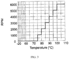
- the preset corresponding relationship between the LED chip temperature and the fan speed is shown in Figure 3 , in which all of the temperature values within any one temperature range correspond to the same fan speed; therefore the corresponding relationship is ladder-like in the figure.
- a minimum preset calculated temperature value t min a maximum preset calculated temperature value t max , a minimum temperature range D min composed of all temperature values lower than the minimum preset calculated temperature value, a maximum temperature range D max composed of all temperature values higher than the maximum preset calculated temperature value, one or more adjusted temperature ranges between the minimum preset calculated temperature value and the maximum preset calculated temperature value, as well as a corresponding fan speed preset on the controller corresponding to the minimum temperature range, maximum temperature range and adjusted temperature range, can be preset on the controller.
- t min can be selected according to models of LED lamps and LED chip, such as 70 degrees, 75 degrees or 80 degrees
- t max can also be selected according to models of LED lamps and LED chip, such as 100 degrees, 105 degrees or 110 degrees.
- the temperature range of the current calculated temperature value T may be determined by the controller at each fixed interval of time. If the current calculated temperature value T is within the minimum temperature range, the fan will be turned off by the controller. If the currently calculated temperature value T is within the maximum temperature range, the fan will be controlled to rotate at the highest speed by the controller. The fan is controlled by the controller to allow the fan to rotate at a corresponding fan speed corresponding to the current temperature range, wherein the current calculated temperature value T is located, if the current calculated temperature value T is within the adjusted temperature range.
- t min is 70 degrees and t max is 110 degrees as an example
- D min is the range composed by all the temperature values less than 70 degrees
- D max is the range composed by all the temperature values greater than 110 degrees.
- 70 degrees to 80 degrees shall be the first adjusted temperature range D1
- 80 degrees to 90 degrees shall be the second adjusted temperature range D2
- 90 degrees to 100 degrees shall be the third adjusted temperature range D3
- 100 degrees to 110 degrees shall be the fourth adjusted temperature range D4.
- the controller can be preset to the following corresponding relationship: t min is corresponding to the fan speed of 0, that is, turning off the fan; t max is corresponding to the fan speed of 6,000 rpm, i.e. the maximum speed of the fan; fan speeds corresponding to temperature ranges D1, D2, D3 and D4 are 1,200 rpm, 2,400 rpm, 3,600 rpm and 4,800 rpm, respectively.
- the temperature range of the current calculated temperature value T is determined by the controller and the fan is controlled to rotate at a corresponding rotational speed according to the temperature range. For example, if T is 68 degrees, the fan is turned off by the controller; if T is 83 degrees, then T is within the D2 adjusted range, the corresponding fan speed is 2,400 rpm, and the controller controls the fan to rotate at a rotational speed of 2,400 rpm; if T is 115 degrees, the fan is controlled to rotate at 6,000 rpm by the controller.
- the fixed time interval is within the range of 0.01 seconds to 10 seconds.
- different control mode may be used by the controller at different stages; for example, during the temperature rising stage, the fan is controlled by the controller in a continuous control mode to rotate at the current desired fan speed, while during the temperature lowering stage, the fan is controlled by the controller in a step-wise control mode to rotate at the current desired fan speed.
- Another aspect of an embodiment of the present invention relates to a system for controlling the rotational speed of a fan in an LED lamp, the system comprising a voltage measuring unit, a current measuring unit and a controller.
- the voltage measuring unit is used to measure the voltage of the LED chip in the LED lamp
- the current measuring unit is used to measure the current of the LED chip
- the controller is used to control the rotational speed of the fan.
- the controller is connected to the voltage measuring unit and the current measuring unit.
- the voltage measurement unit, the current measurement unit, and the controller may be integrated into the microcontroller and the integrated chip.
- the controller may be connected to an amplifier which is used to read the measured voltage and the measured current of the LED chip.
- the controller has a corresponding relationship between the voltage, current and temperature of the LED chip, and a corresponding relationship between the temperature and fan speed of the LED chip. Furthermore, the controller is configured to determine LED chip's current calculated temperature according to the voltage measured by the voltage measuring unit, the current measured by the current measuring unit, as well as the preset corresponding relationship between the voltage, current and temperature of the LED chip; to determine the current desired fan speed through the current calculated temperature and the corresponding relationship between the temperature and fan speed of the LED chip; as well as to control the fan to rotate at the current desired fan rotational speed. As previously described, the controller may be configured to control the fan to rotate at the current desired fan speed in the continuous control mode or stepwise control mode. The specific approach to the control mode has been described and explained in the previous paragraph, and will not be repeated here.
- Embodiments of the present invention also relate to an LED lamp using the control method and system, the LED lamp comprising an LED chip, a fan for cooling the LED chip, and a system for controlling the rotational speed of the fan.
- the LED chip is any LED light emitting unit.
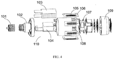
- Figure 4 is an exploded view of an assembly of an LED lamp 100 including a system for controlling the rotational speed of a fan, wherein the LED lamp 100 includes a lamp cap 101, an upper cover 102, a Mylar case 103, a drive device 104 including a controller, an LED light source board 106 composed of an LED chip 105, a fan 107, a heat sink 108, a bottom cover 109, and a control system 110 for controlling the rotational speed of the fan 107.
- the LED lamp 100 includes a lamp cap 101, an upper cover 102, a Mylar case 103, a drive device 104 including a controller, an LED light source board 106 composed of an LED chip 105, a fan 107, a heat sink 108, a bottom cover 109, and a control system 110 for controlling the rotational speed of the fan 107.
- the Mylar case 103 is used to insulate the drive device 104 including the controller from the heat sink 108, which is used to cool the LED chip 105, and the heat sink 108 is used to increase the heat dissipation area of the LED light source board 105.
- the drive device 104 including the controller is integrated with a controller, a driver, a voltage measuring unit and a current measuring unit.
- the lamp cap 101 is connected to the upper cover 102 by a thread, the drive including the controller is fixed to the upper cover 102 by glue, the heat sink 108 is connected to the upper cover 102 by screws, while the fan 107, the light source plate 105, the bottom cover 109 are fixed to the heat sink 108 by screws.
- the corresponding relationship between the voltage, current and temperature of the LED chip 105 and the corresponding relationship between the temperature of the LED chip 105 and the rotational speed of the fan 107 are preset in the driving device 104.
- the drive device 104 including the controller may be configured to determine the current calculated temperature according to the current measured by the current measurement unit, the voltage measured by the voltage measurement unit and the preset corresponding relationship between the voltage, current and temperature of the LED chip 105; and determine the current desired rotational speed of the fan 107 and control the fan 107 to rotate at the current desired fan 107 speed according to the current calculated temperature and the corresponding relationship between the temperature of the LED chip 105 and the speed of the fan 107.
- the specific control method may be the same as or similar to that described above, and will not be described again.
Landscapes
- Engineering & Computer Science (AREA)
- General Engineering & Computer Science (AREA)
- Microelectronics & Electronic Packaging (AREA)
- Mechanical Engineering (AREA)
- Physics & Mathematics (AREA)
- Thermal Sciences (AREA)
- Circuit Arrangement For Electric Light Sources In General (AREA)
- Arrangement Of Elements, Cooling, Sealing, Or The Like Of Lighting Devices (AREA)
Applications Claiming Priority (1)
| Application Number | Priority Date | Filing Date | Title |
|---|---|---|---|
| CN201611108588.8A CN108150979B (zh) | 2016-12-06 | 2016-12-06 | Led灯及控制led灯的风扇转速的方法及其系统 |
Publications (1)
| Publication Number | Publication Date |
|---|---|
| EP3333430A1 true EP3333430A1 (de) | 2018-06-13 |
Family
ID=60813570
Family Applications (1)
| Application Number | Title | Priority Date | Filing Date |
|---|---|---|---|
| EP17204994.2A Withdrawn EP3333430A1 (de) | 2016-12-06 | 2017-12-01 | Verfahren und system zur steuerung der gebläsedrehzahl einer led-lampe und led-lampe damit |
Country Status (4)
| Country | Link |
|---|---|
| US (1) | US10225949B2 (de) |
| EP (1) | EP3333430A1 (de) |
| CN (1) | CN108150979B (de) |
| CA (1) | CA2986407C (de) |
Families Citing this family (9)
| Publication number | Priority date | Publication date | Assignee | Title |
|---|---|---|---|---|
| EP3653946B1 (de) * | 2017-10-19 | 2023-07-05 | GD Midea Air-Conditioning Equipment Co., Ltd. | Klimaanlage, steuerungsverfahren und vorrichtung dafür sowie computerlesbares speichermedium |
| JP7300899B2 (ja) * | 2019-06-13 | 2023-06-30 | Hoya株式会社 | 光源装置 |
| CN110803105B (zh) * | 2019-11-15 | 2021-06-01 | 北京海纳川汽车部件股份有限公司 | 汽车车灯的控制方法、装置及汽车 |
| CN114183383B (zh) * | 2020-09-15 | 2024-08-30 | 海韵电子工业股份有限公司 | 避免电源输出状态骤变导致控制失准的风扇转速控制方法 |
| CN112181010B (zh) * | 2020-09-23 | 2022-03-01 | 普联国际有限公司 | 一种路由器的温度控制方法、装置、存储介质及路由器 |
| CN114220459A (zh) * | 2021-11-30 | 2022-03-22 | 歌尔光学科技有限公司 | 电子设备的控制方法、装置、电子设备及可读存储介质 |
| CN116412161A (zh) * | 2021-12-31 | 2023-07-11 | 杭州诺沁医疗器械有限公司 | 一种风扇调节方法及应用该方法的装置及存储介质 |
| CN115971962B (zh) * | 2022-12-16 | 2025-07-01 | 广州市雅江光电设备有限公司 | 一种应用于切割灯具切割片的散热方法、系统及存储介质 |
| CN117202466B (zh) * | 2023-11-06 | 2024-02-06 | 湖南华鑫电子科技有限公司 | 一种有过温保护功能的照明电源集中控制方法和系统 |
Citations (3)
| Publication number | Priority date | Publication date | Assignee | Title |
|---|---|---|---|---|
| US20120280620A1 (en) * | 2011-05-02 | 2012-11-08 | Tyco Electronics Corporation | Light emitting diode assembly having active cooling |
| US20130200707A1 (en) * | 2010-04-09 | 2013-08-08 | Tridonic Ag | Modular LED Lighting Having an Emergency Light Function |
| US20160334091A1 (en) * | 2015-05-15 | 2016-11-17 | Posco Led Company Ltd. | Led lighting apparatus |
Family Cites Families (37)
| Publication number | Priority date | Publication date | Assignee | Title |
|---|---|---|---|---|
| US7344279B2 (en) | 2003-12-11 | 2008-03-18 | Philips Solid-State Lighting Solutions, Inc. | Thermal management methods and apparatus for lighting devices |
| CN100410826C (zh) * | 2004-10-09 | 2008-08-13 | 华为技术有限公司 | 温控风扇转速的控制装置及控制方法 |
| CN100346262C (zh) * | 2005-01-05 | 2007-10-31 | 英业达股份有限公司 | 风扇转速控制系统及方法 |
| JP2008248747A (ja) * | 2007-03-29 | 2008-10-16 | Nec Corp | ファン制御装置、及びファン制御方法 |
| US20080304303A1 (en) * | 2007-06-05 | 2008-12-11 | World Friendship Co., Ltd. | Power converting device |
| JP4301341B2 (ja) * | 2007-11-16 | 2009-07-22 | ダイキン工業株式会社 | モータ電流算出装置ならびに空気調和装置 |
| TW200925839A (en) * | 2007-12-13 | 2009-06-16 | Inventec Corp | Intelligent cooling fan device and fan rotation speed controlling method thereof |
| CN100557303C (zh) | 2007-12-14 | 2009-11-04 | 广州市雅江光电设备有限公司 | 一种控制led灯ic工作温度的方法 |
| TW200926892A (en) * | 2007-12-14 | 2009-06-16 | Delta Electronics Inc | Driving circuit and method for reducing operation temperature of LED |
| US10539311B2 (en) * | 2008-04-14 | 2020-01-21 | Digital Lumens Incorporated | Sensor-based lighting methods, apparatus, and systems |
| TWM346050U (en) * | 2008-04-28 | 2008-12-01 | Lian Li Ind Co Ltd | Heat dissipating device |
| TW200947199A (en) * | 2008-05-09 | 2009-11-16 | Asustek Comp Inc | Status signal displaying system |
| US8237377B2 (en) | 2008-12-11 | 2012-08-07 | Michael Blair Hopper | Energy efficient lighting system and method |
| US20100277077A1 (en) * | 2009-05-04 | 2010-11-04 | Man Hay Pong | Apparatus and method to enhance the life of Light Emitting diode (LED) devices in an LED matrix |
| CN201396607Y (zh) | 2009-05-14 | 2010-02-03 | 戴高峰 | 一种大功率集成led光源照明灯具 |
| TW201043087A (en) * | 2009-05-18 | 2010-12-01 | Young Bright Technology Corp | Illumination device and control method thereof |
| CN201628116U (zh) | 2010-03-16 | 2010-11-10 | 浙江上光照明有限公司 | 大功率led照明灯 |
| TW201212806A (en) * | 2010-09-15 | 2012-03-16 | Wistron Corp | Fan speed control method and related computer system |
| CN102748311B (zh) * | 2011-04-21 | 2015-09-09 | 台达电子工业股份有限公司 | 风扇转速的控制方法 |
| CN202587492U (zh) | 2012-03-28 | 2012-12-05 | 李洪资 | 一种大功率led恒压稳流驱动式光源 |
| US9310439B2 (en) * | 2012-09-25 | 2016-04-12 | Emerson Climate Technologies, Inc. | Compressor having a control and diagnostic module |
| TWI498484B (zh) * | 2012-11-19 | 2015-09-01 | Wistron Corp | 風扇控制系統、電腦系統及其風扇控制之方法 |
| CN102944737B (zh) * | 2012-11-22 | 2014-12-24 | 中国科学院电工研究所 | 一种测量大电流的智能传感器 |
| JP2014107336A (ja) * | 2012-11-26 | 2014-06-09 | Canon Inc | 電子機器及びその制御方法、並びにプログラム |
| TWI531725B (zh) * | 2013-01-03 | 2016-05-01 | 茂達電子股份有限公司 | 風扇控制電路及風扇控制系統 |
| CN104019049B (zh) * | 2013-03-01 | 2016-08-10 | 鸿富锦精密电子(天津)有限公司 | 风扇转速测试装置 |
| TW201437490A (zh) * | 2013-03-27 | 2014-10-01 | Hon Hai Prec Ind Co Ltd | 風扇控制系統及方法 |
| TWI540262B (zh) * | 2013-08-14 | 2016-07-01 | 緯創資通股份有限公司 | 風扇控制系統及控制風扇轉速之方法 |
| CN104424067A (zh) * | 2013-08-28 | 2015-03-18 | 鸿富锦精密工业(深圳)有限公司 | 风扇模组测试方法及系统 |
| CN104564764B (zh) * | 2013-10-12 | 2016-09-21 | 英业达科技有限公司 | 服务器系统 |
| CN104863881B (zh) * | 2014-02-21 | 2018-10-23 | 南京中兴新软件有限责任公司 | 电子设备中风扇转速的控制方法及装置 |
| TW201533564A (zh) * | 2014-02-27 | 2015-09-01 | 萬國商業機器公司 | 電腦系統中基於功率比値的風扇控制系統與方法 |
| KR20160087988A (ko) * | 2015-01-14 | 2016-07-25 | 삼성디스플레이 주식회사 | 엘이디 온도 측정 장치 및 그것의 온도 측정 방법 |
| CN104808715B (zh) * | 2015-03-11 | 2017-04-12 | 北京工业大学 | 一种芯片级GaAs功率器件、微波单片电路表面温度检测方法 |
| US10444006B2 (en) * | 2015-08-19 | 2019-10-15 | Faro Technologies, Inc. | Three-dimensional imager |
| CN105628243B (zh) * | 2015-12-30 | 2018-04-20 | 清华大学深圳研究生院 | 一种电阻型温度传感芯片 |
| US9795006B2 (en) * | 2016-03-13 | 2017-10-17 | Yvette Seifert Hirth | Low-voltage alternating current-based led light with built-in cooling and automatic or manual dimming |
-
2016
- 2016-12-06 CN CN201611108588.8A patent/CN108150979B/zh active Active
-
2017
- 2017-11-22 CA CA2986407A patent/CA2986407C/en active Active
- 2017-12-01 EP EP17204994.2A patent/EP3333430A1/de not_active Withdrawn
- 2017-12-06 US US15/833,568 patent/US10225949B2/en active Active
Patent Citations (3)
| Publication number | Priority date | Publication date | Assignee | Title |
|---|---|---|---|---|
| US20130200707A1 (en) * | 2010-04-09 | 2013-08-08 | Tridonic Ag | Modular LED Lighting Having an Emergency Light Function |
| US20120280620A1 (en) * | 2011-05-02 | 2012-11-08 | Tyco Electronics Corporation | Light emitting diode assembly having active cooling |
| US20160334091A1 (en) * | 2015-05-15 | 2016-11-17 | Posco Led Company Ltd. | Led lighting apparatus |
Non-Patent Citations (1)
| Title |
|---|
| A. KEPPENS; WR RYCKAERT; G. DECONINCK; P. HANSELAER, JOURNAL OF APPLIED PHYSICS, October 2008 (2008-10-01) |
Also Published As
| Publication number | Publication date |
|---|---|
| US10225949B2 (en) | 2019-03-05 |
| CA2986407A1 (en) | 2018-06-06 |
| CN108150979B (zh) | 2020-02-18 |
| CN108150979A (zh) | 2018-06-12 |
| US20180160564A1 (en) | 2018-06-07 |
| CA2986407C (en) | 2025-12-23 |
Similar Documents
| Publication | Publication Date | Title |
|---|---|---|
| US10225949B2 (en) | Method and system for controlling fan rotating speed of LED lamp, and LED lamp thereof | |
| US11877362B2 (en) | Light emitting diode thermal foldback control device and method | |
| US20090020685A1 (en) | Light emitting device and its calibrating and control methods | |
| US20090184619A1 (en) | Led illuminantor and heat-dissipating method thereof | |
| CN103843460B (zh) | 用于固态灯泡组件的控制器 | |
| US20130049603A1 (en) | Modularized led lamp | |
| TW201542033A (zh) | 一種用於led triac調光自適應控制的系統和方法 | |
| TW201322828A (zh) | 色溫調節系統及方法 | |
| JP5795803B2 (ja) | 並列フライバックコンバータ段を有する発光ダイオード(led)を駆動する方法及び装置 | |
| CN105103656B (zh) | 用于运行led光源的方法和电路组件 | |
| KR101285396B1 (ko) | 발광장치 및 발광장치 제어방법 | |
| CN116723600A (zh) | 一种led照度输出的控制方法、系统 | |
| TWI703895B (zh) | 路燈控制裝置以及路燈控制方法 | |
| EP2748688B1 (de) | Vorrichtung zur steuerung einer speichervorrichtung | |
| KR101664455B1 (ko) | 조명 연속 유지 성능을 갖는 led 컨버터 모듈 일체형 전력 제어 장치 및 그 방법 | |
| JP2015167166A (ja) | Led並列点灯回路 | |
| CN110784100B (zh) | 功率转换装置及功率管理方法 | |
| US20140346964A1 (en) | Application circuit and control method thereof | |
| TWM492968U (zh) | 具有背光折射結構的風扇裝置 | |
| CN204836650U (zh) | 一种可直接连接在可调光驱动电源调光端口的恒温控制器 | |
| KR20200026145A (ko) | Led 조명 제어 시스템 | |
| KR101966783B1 (ko) | 광원 모듈 | |
| CN200947184Y (zh) | 散热风扇转速控制电路 | |
| CN105120558A (zh) | 恒温恒流led驱动方法和装置 | |
| JP2016024931A (ja) | Ledアレイ駆動回路 |
Legal Events
| Date | Code | Title | Description |
|---|---|---|---|
| PUAI | Public reference made under article 153(3) epc to a published international application that has entered the european phase |
Free format text: ORIGINAL CODE: 0009012 |
|
| STAA | Information on the status of an ep patent application or granted ep patent |
Free format text: STATUS: THE APPLICATION HAS BEEN PUBLISHED |
|
| AK | Designated contracting states |
Kind code of ref document: A1 Designated state(s): AL AT BE BG CH CY CZ DE DK EE ES FI FR GB GR HR HU IE IS IT LI LT LU LV MC MK MT NL NO PL PT RO RS SE SI SK SM TR |
|
| AX | Request for extension of the european patent |
Extension state: BA ME |
|
| STAA | Information on the status of an ep patent application or granted ep patent |
Free format text: STATUS: REQUEST FOR EXAMINATION WAS MADE |
|
| 17P | Request for examination filed |
Effective date: 20181213 |
|
| RBV | Designated contracting states (corrected) |
Designated state(s): AL AT BE BG CH CY CZ DE DK EE ES FI FR GB GR HR HU IE IS IT LI LT LU LV MC MK MT NL NO PL PT RO RS SE SI SK SM TR |
|
| STAA | Information on the status of an ep patent application or granted ep patent |
Free format text: STATUS: EXAMINATION IS IN PROGRESS |
|
| 17Q | First examination report despatched |
Effective date: 20191210 |
|
| STAA | Information on the status of an ep patent application or granted ep patent |
Free format text: STATUS: THE APPLICATION IS DEEMED TO BE WITHDRAWN |
|
| 18D | Application deemed to be withdrawn |
Effective date: 20200623 |