EP3333406A1 - Intake manifold with built-in heat exchanger - Google Patents
Intake manifold with built-in heat exchanger Download PDFInfo
- Publication number
- EP3333406A1 EP3333406A1 EP17205504.8A EP17205504A EP3333406A1 EP 3333406 A1 EP3333406 A1 EP 3333406A1 EP 17205504 A EP17205504 A EP 17205504A EP 3333406 A1 EP3333406 A1 EP 3333406A1
- Authority
- EP
- European Patent Office
- Prior art keywords
- exchanger
- housing
- distributor
- support
- shaped
- Prior art date
- Legal status (The legal status is an assumption and is not a legal conclusion. Google has not performed a legal analysis and makes no representation as to the accuracy of the status listed.)
- Granted
Links
- 238000007789 sealing Methods 0.000 claims abstract description 30
- 230000002093 peripheral effect Effects 0.000 claims abstract description 25
- 230000000295 complement effect Effects 0.000 claims abstract description 9
- 238000002485 combustion reaction Methods 0.000 claims abstract description 8
- 230000004888 barrier function Effects 0.000 claims abstract description 5
- 230000015572 biosynthetic process Effects 0.000 claims description 22
- 238000005755 formation reaction Methods 0.000 claims description 22
- 239000000470 constituent Substances 0.000 claims description 9
- 239000000463 material Substances 0.000 claims description 7
- 238000004519 manufacturing process Methods 0.000 claims description 6
- 239000004033 plastic Substances 0.000 claims description 3
- 210000002105 tongue Anatomy 0.000 claims description 3
- 229920002302 Nylon 6,6 Polymers 0.000 claims description 2
- 238000004026 adhesive bonding Methods 0.000 claims description 2
- 230000005489 elastic deformation Effects 0.000 claims description 2
- 239000012815 thermoplastic material Substances 0.000 claims description 2
- 238000003466 welding Methods 0.000 claims description 2
- 229920002725 thermoplastic elastomer Polymers 0.000 claims 1
- 239000007789 gas Substances 0.000 description 11
- 238000010276 construction Methods 0.000 description 3
- 238000009826 distribution Methods 0.000 description 3
- 238000000034 method Methods 0.000 description 2
- 239000000243 solution Substances 0.000 description 2
- 230000009471 action Effects 0.000 description 1
- 230000000903 blocking effect Effects 0.000 description 1
- 210000004027 cell Anatomy 0.000 description 1
- 239000002131 composite material Substances 0.000 description 1
- 238000000354 decomposition reaction Methods 0.000 description 1
- 230000001419 dependent effect Effects 0.000 description 1
- 238000006073 displacement reaction Methods 0.000 description 1
- 229920001971 elastomer Polymers 0.000 description 1
- 239000000806 elastomer Substances 0.000 description 1
- 239000008246 gaseous mixture Substances 0.000 description 1
- 238000011065 in-situ storage Methods 0.000 description 1
- 238000002347 injection Methods 0.000 description 1
- 239000007924 injection Substances 0.000 description 1
- 238000003780 insertion Methods 0.000 description 1
- 230000037431 insertion Effects 0.000 description 1
- 238000009434 installation Methods 0.000 description 1
- 230000010354 integration Effects 0.000 description 1
- 230000003993 interaction Effects 0.000 description 1
- 238000005304 joining Methods 0.000 description 1
- 230000014759 maintenance of location Effects 0.000 description 1
- 238000012986 modification Methods 0.000 description 1
- 230000004048 modification Effects 0.000 description 1
- 230000001590 oxidative effect Effects 0.000 description 1
- 230000008569 process Effects 0.000 description 1
- 238000006467 substitution reaction Methods 0.000 description 1
- 229920001169 thermoplastic Polymers 0.000 description 1
- 239000004416 thermosoftening plastic Substances 0.000 description 1
Images


Classifications
-
- F—MECHANICAL ENGINEERING; LIGHTING; HEATING; WEAPONS; BLASTING
- F02—COMBUSTION ENGINES; HOT-GAS OR COMBUSTION-PRODUCT ENGINE PLANTS
- F02B—INTERNAL-COMBUSTION PISTON ENGINES; COMBUSTION ENGINES IN GENERAL
- F02B29/00—Engines characterised by provision for charging or scavenging not provided for in groups F02B25/00, F02B27/00 or F02B33/00 - F02B39/00; Details thereof
- F02B29/04—Cooling of air intake supply
- F02B29/045—Constructional details of the heat exchangers, e.g. pipes, plates, ribs, insulation, materials, or manufacturing and assembly
- F02B29/0475—Constructional details of the heat exchangers, e.g. pipes, plates, ribs, insulation, materials, or manufacturing and assembly the intake air cooler being combined with another device, e.g. heater, valve, compressor, filter or EGR cooler, or being assembled on a special engine location
-
- F—MECHANICAL ENGINEERING; LIGHTING; HEATING; WEAPONS; BLASTING
- F02—COMBUSTION ENGINES; HOT-GAS OR COMBUSTION-PRODUCT ENGINE PLANTS
- F02M—SUPPLYING COMBUSTION ENGINES IN GENERAL WITH COMBUSTIBLE MIXTURES OR CONSTITUENTS THEREOF
- F02M35/00—Combustion-air cleaners, air intakes, intake silencers, or induction systems specially adapted for, or arranged on, internal-combustion engines
- F02M35/10—Air intakes; Induction systems
- F02M35/10242—Devices or means connected to or integrated into air intakes; Air intakes combined with other engine or vehicle parts
- F02M35/10268—Heating, cooling or thermal insulating means
-
- F—MECHANICAL ENGINEERING; LIGHTING; HEATING; WEAPONS; BLASTING
- F02—COMBUSTION ENGINES; HOT-GAS OR COMBUSTION-PRODUCT ENGINE PLANTS
- F02B—INTERNAL-COMBUSTION PISTON ENGINES; COMBUSTION ENGINES IN GENERAL
- F02B29/00—Engines characterised by provision for charging or scavenging not provided for in groups F02B25/00, F02B27/00 or F02B33/00 - F02B39/00; Details thereof
- F02B29/04—Cooling of air intake supply
- F02B29/045—Constructional details of the heat exchangers, e.g. pipes, plates, ribs, insulation, materials, or manufacturing and assembly
-
- F—MECHANICAL ENGINEERING; LIGHTING; HEATING; WEAPONS; BLASTING
- F02—COMBUSTION ENGINES; HOT-GAS OR COMBUSTION-PRODUCT ENGINE PLANTS
- F02M—SUPPLYING COMBUSTION ENGINES IN GENERAL WITH COMBUSTIBLE MIXTURES OR CONSTITUENTS THEREOF
- F02M35/00—Combustion-air cleaners, air intakes, intake silencers, or induction systems specially adapted for, or arranged on, internal-combustion engines
- F02M35/10—Air intakes; Induction systems
- F02M35/10242—Devices or means connected to or integrated into air intakes; Air intakes combined with other engine or vehicle parts
- F02M35/10288—Air intakes combined with another engine part, e.g. cylinder head cover or being cast in one piece with the exhaust manifold, cylinder head or engine block
-
- F—MECHANICAL ENGINEERING; LIGHTING; HEATING; WEAPONS; BLASTING
- F02—COMBUSTION ENGINES; HOT-GAS OR COMBUSTION-PRODUCT ENGINE PLANTS
- F02M—SUPPLYING COMBUSTION ENGINES IN GENERAL WITH COMBUSTIBLE MIXTURES OR CONSTITUENTS THEREOF
- F02M35/00—Combustion-air cleaners, air intakes, intake silencers, or induction systems specially adapted for, or arranged on, internal-combustion engines
- F02M35/10—Air intakes; Induction systems
- F02M35/1034—Manufacturing and assembling intake systems
-
- F—MECHANICAL ENGINEERING; LIGHTING; HEATING; WEAPONS; BLASTING
- F02—COMBUSTION ENGINES; HOT-GAS OR COMBUSTION-PRODUCT ENGINE PLANTS
- F02M—SUPPLYING COMBUSTION ENGINES IN GENERAL WITH COMBUSTIBLE MIXTURES OR CONSTITUENTS THEREOF
- F02M35/00—Combustion-air cleaners, air intakes, intake silencers, or induction systems specially adapted for, or arranged on, internal-combustion engines
- F02M35/10—Air intakes; Induction systems
- F02M35/104—Intake manifolds
-
- F—MECHANICAL ENGINEERING; LIGHTING; HEATING; WEAPONS; BLASTING
- F16—ENGINEERING ELEMENTS AND UNITS; GENERAL MEASURES FOR PRODUCING AND MAINTAINING EFFECTIVE FUNCTIONING OF MACHINES OR INSTALLATIONS; THERMAL INSULATION IN GENERAL
- F16J—PISTONS; CYLINDERS; SEALINGS
- F16J15/00—Sealings
- F16J15/02—Sealings between relatively-stationary surfaces
- F16J15/021—Sealings between relatively-stationary surfaces with elastic packing
- F16J15/022—Sealings between relatively-stationary surfaces with elastic packing characterised by structure or material
- F16J15/024—Sealings between relatively-stationary surfaces with elastic packing characterised by structure or material the packing being locally weakened in order to increase elasticity
- F16J15/025—Sealings between relatively-stationary surfaces with elastic packing characterised by structure or material the packing being locally weakened in order to increase elasticity and with at least one flexible lip
-
- F—MECHANICAL ENGINEERING; LIGHTING; HEATING; WEAPONS; BLASTING
- F16—ENGINEERING ELEMENTS AND UNITS; GENERAL MEASURES FOR PRODUCING AND MAINTAINING EFFECTIVE FUNCTIONING OF MACHINES OR INSTALLATIONS; THERMAL INSULATION IN GENERAL
- F16J—PISTONS; CYLINDERS; SEALINGS
- F16J15/00—Sealings
- F16J15/02—Sealings between relatively-stationary surfaces
- F16J15/06—Sealings between relatively-stationary surfaces with solid packing compressed between sealing surfaces
- F16J15/062—Sealings between relatively-stationary surfaces with solid packing compressed between sealing surfaces characterised by the geometry of the seat
-
- F—MECHANICAL ENGINEERING; LIGHTING; HEATING; WEAPONS; BLASTING
- F28—HEAT EXCHANGE IN GENERAL
- F28F—DETAILS OF HEAT-EXCHANGE AND HEAT-TRANSFER APPARATUS, OF GENERAL APPLICATION
- F28F9/00—Casings; Header boxes; Auxiliary supports for elements; Auxiliary members within casings
- F28F9/001—Casings in the form of plate-like arrangements; Frames enclosing a heat exchange core
-
- F—MECHANICAL ENGINEERING; LIGHTING; HEATING; WEAPONS; BLASTING
- F28—HEAT EXCHANGE IN GENERAL
- F28F—DETAILS OF HEAT-EXCHANGE AND HEAT-TRANSFER APPARATUS, OF GENERAL APPLICATION
- F28F9/00—Casings; Header boxes; Auxiliary supports for elements; Auxiliary members within casings
- F28F9/005—Other auxiliary members within casings, e.g. internal filling means or sealing means
-
- F—MECHANICAL ENGINEERING; LIGHTING; HEATING; WEAPONS; BLASTING
- F28—HEAT EXCHANGE IN GENERAL
- F28F—DETAILS OF HEAT-EXCHANGE AND HEAT-TRANSFER APPARATUS, OF GENERAL APPLICATION
- F28F9/00—Casings; Header boxes; Auxiliary supports for elements; Auxiliary members within casings
- F28F9/007—Auxiliary supports for elements
-
- F—MECHANICAL ENGINEERING; LIGHTING; HEATING; WEAPONS; BLASTING
- F02—COMBUSTION ENGINES; HOT-GAS OR COMBUSTION-PRODUCT ENGINE PLANTS
- F02B—INTERNAL-COMBUSTION PISTON ENGINES; COMBUSTION ENGINES IN GENERAL
- F02B29/00—Engines characterised by provision for charging or scavenging not provided for in groups F02B25/00, F02B27/00 or F02B33/00 - F02B39/00; Details thereof
- F02B29/04—Cooling of air intake supply
- F02B29/045—Constructional details of the heat exchangers, e.g. pipes, plates, ribs, insulation, materials, or manufacturing and assembly
- F02B29/0462—Liquid cooled heat exchangers
-
- F—MECHANICAL ENGINEERING; LIGHTING; HEATING; WEAPONS; BLASTING
- F02—COMBUSTION ENGINES; HOT-GAS OR COMBUSTION-PRODUCT ENGINE PLANTS
- F02M—SUPPLYING COMBUSTION ENGINES IN GENERAL WITH COMBUSTIBLE MIXTURES OR CONSTITUENTS THEREOF
- F02M35/00—Combustion-air cleaners, air intakes, intake silencers, or induction systems specially adapted for, or arranged on, internal-combustion engines
- F02M35/10—Air intakes; Induction systems
- F02M35/10314—Materials for intake systems
- F02M35/10321—Plastics; Composites; Rubbers
-
- F—MECHANICAL ENGINEERING; LIGHTING; HEATING; WEAPONS; BLASTING
- F28—HEAT EXCHANGE IN GENERAL
- F28D—HEAT-EXCHANGE APPARATUS, NOT PROVIDED FOR IN ANOTHER SUBCLASS, IN WHICH THE HEAT-EXCHANGE MEDIA DO NOT COME INTO DIRECT CONTACT
- F28D21/00—Heat-exchange apparatus not covered by any of the groups F28D1/00 - F28D20/00
- F28D2021/0019—Other heat exchangers for particular applications; Heat exchange systems not otherwise provided for
- F28D2021/0026—Other heat exchangers for particular applications; Heat exchange systems not otherwise provided for for combustion engines, e.g. for gas turbines or for Stirling engines
-
- F—MECHANICAL ENGINEERING; LIGHTING; HEATING; WEAPONS; BLASTING
- F28—HEAT EXCHANGE IN GENERAL
- F28D—HEAT-EXCHANGE APPARATUS, NOT PROVIDED FOR IN ANOTHER SUBCLASS, IN WHICH THE HEAT-EXCHANGE MEDIA DO NOT COME INTO DIRECT CONTACT
- F28D21/00—Heat-exchange apparatus not covered by any of the groups F28D1/00 - F28D20/00
- F28D2021/0019—Other heat exchangers for particular applications; Heat exchange systems not otherwise provided for
- F28D2021/008—Other heat exchangers for particular applications; Heat exchange systems not otherwise provided for for vehicles
- F28D2021/0082—Charged air coolers
-
- F—MECHANICAL ENGINEERING; LIGHTING; HEATING; WEAPONS; BLASTING
- F28—HEAT EXCHANGE IN GENERAL
- F28F—DETAILS OF HEAT-EXCHANGE AND HEAT-TRANSFER APPARATUS, OF GENERAL APPLICATION
- F28F2225/00—Reinforcing means
- F28F2225/02—Reinforcing means for casings
-
- F—MECHANICAL ENGINEERING; LIGHTING; HEATING; WEAPONS; BLASTING
- F28—HEAT EXCHANGE IN GENERAL
- F28F—DETAILS OF HEAT-EXCHANGE AND HEAT-TRANSFER APPARATUS, OF GENERAL APPLICATION
- F28F2230/00—Sealing means
-
- Y—GENERAL TAGGING OF NEW TECHNOLOGICAL DEVELOPMENTS; GENERAL TAGGING OF CROSS-SECTIONAL TECHNOLOGIES SPANNING OVER SEVERAL SECTIONS OF THE IPC; TECHNICAL SUBJECTS COVERED BY FORMER USPC CROSS-REFERENCE ART COLLECTIONS [XRACs] AND DIGESTS
- Y02—TECHNOLOGIES OR APPLICATIONS FOR MITIGATION OR ADAPTATION AGAINST CLIMATE CHANGE
- Y02T—CLIMATE CHANGE MITIGATION TECHNOLOGIES RELATED TO TRANSPORTATION
- Y02T10/00—Road transport of goods or passengers
- Y02T10/10—Internal combustion engine [ICE] based vehicles
- Y02T10/12—Improving ICE efficiencies
Definitions
- the present invention relates to the field of technical equipment of motor vehicles with internal combustion engine, more particularly the elements and components forming the intake line of the oxidizing gases of these engines.
- the invention in this context, relates to a distributor or intake manifold incorporating a heat exchanger.
- a constant demand, or even a permanent constructive constraint, in the field of automobile manufacturing, is the saving of space, particularly under the hood and in the engine environment.
- intake manifolds for internal combustion engine incorporating at least one heat exchanger mounted in the interior volume of said collector, that is to say, hermetically encapsulated.
- said interior volume is separated into two compartments located on either side of said exchanger, and that the flow of gas flowing in the collector passes through said exchanger to pass from a first of said compartments to the second compartment.
- the integrated heat exchanger is produced in situ in cooperation with the collector body, some parts serving simultaneously to the exchanger and the collector.
- the functional parts of the exchanger are assembled with the walls of the collector by providing a double seal, namely the sealing of the exchanger itself and the sealing of the latter vis-à- collector screw.
- the exchanger is provided with a peripheral frame which is sandwiched during assembly of the two parts of the splitter box.
- the frame thus ensures rigid attachment of the exchanger in the housing and a peripheral seal around the exchanger.
- the heat exchanger is made separately and then mounted in the body of the distributor when the latter is already largely assembled (cf. WO 2008/061850 , DE 10 2007 030 464 , WO 2009/027492 or FR 2 645 209 ) or by being integrated during assembly of the different parts of the distributor (cf. FR 2 936 572 , WO 2011/064087 or FR 2 908 833 ).
- the position of the exchanger is maintained by blocking in the body of the distributor or by securing it to the wall of the latter, possibly by means of a plate or a cross member. sealing of the distributor being managed independently.
- peripheral sealing means around the exchanger are also known (sealed barrier between the outer faces of the exchanger and the inner wall of the splitter box).
- the object of the present invention is to propose a constructive solution of a distributor integrating an exchanger, in which the assembly and peripheral sealing functions around the exchanger are differentiated structurally and spatially, while providing a seal adapting to dimensional variations. differentiated from the exchanger and the distributor (different thermal expansion coefficients), easy and quick to assemble, possibly being made of several materials adapted to the location and can advantageously be assembled in a resistant and precise manner with the exchanger, even before it is mounted in the splitter box.
- the heat exchanger structurally integrated into the distribution frame should not be dependent on a mounting bracket which also forms a closing cover for the distribution box, so as to allow a more flexible mounting therein.
- the subject of the invention is an intake manifold or manifold for an internal combustion engine, in particular a supercharged intake air distributor, comprising a heat exchanger whose body has a generally parallelepipedal shape, which is mounted in the housing said distributor and which is intended to be exposed to the gas flow passing through said housing, said exchanger comprising or being integral with a plate or a cross support and fixing, attached to or forming a face of the body of the exchanger and ensuring its rigid mounting in this housing, said exchanger being positioned in said casing with the formation of an interstitial volume between them, substantially enveloping the body of said exchanger, and peripheral sealing means being attached to the body of the exchanger and to the support plate and fastening so as to form a substantially continuous circumferential sealing barrier between the latter and the splitter box, dividing peripherally the interstitial volume in two, advantageously in a plane substantially perpendicular to the flow direction of the gas flow passing through said exchanger, distributor characterized in that the plane of subdivision of the interstitial
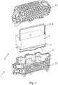
- FIGS. 1 and 2 and partially figures 3 , 4 , 8 and 9 , illustrate an intake manifold or manifold for an internal combustion engine, comprising a heat exchanger 2 whose body 2 'has a generally parallelepipedal shape, which is mounted in the housing 1' of said distributor 1 and which is intended to be exposed the gas flow F passing through said housing 1 '.
- This exchanger 2 comprises or is integral with a plate or a crosspiece 3 of support and attachment, attached to or forming a face 4 of the body 2 'of the exchanger 2 and ensuring its rigid mounting in this housing 1'.
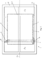
- This exchanger 2 is positioned in said housing 1 'with formation of an interstitial volume 5 between them, substantially surrounding the body 2' of said exchanger 2, and peripheral sealing means 6, 7 are attached to the body 2 'of the exchanger 2 and on the plate or cross support and fixing 3 so as to form a substantially continuous circumferential sealing barrier between the latter and the housing 1 'of the distributor 1, dividing peripherally the interstitial volume 5 in two, preferably in a plane P substantially perpendicular to the flow direction of the gas flow F passing through said exchanger 2.
- the housing 1 ' may, for example, be formed by assembling the two parts (lower 22 and upper 22') in the form of shells ( figure 1 ).
- the subdivision plane P of the interstitial volume 5 is distinct from the main plane of the plate or of the support and fixing crosspiece 3, and advantageously inclined and preferably substantially perpendicular to the latter. .
- peripheral sealing means are constituted by two complementary components 6 and 7 interconnected and secured to the exchanger 2, namely, a first component 6 in the form of a U-shaped seal on the three faces 4 ', 4 ", 4'" of the body 2 'of the exchanger 2 not associated with the crossbar or the support and fixing plate 3, and a second component 7 in the form of a substantially linear seal reported on the face 4 associated with said crosspiece or plate 3, said substantially linear seal 7 being abutting and mechanically assembled, at its two opposite longitudinal ends 7 ', 7 ", with the free ends 9 of the two branches 8, 8' of the seal in U 6.
- a two-part constitution of the continuous peripheral sealing 6, 7 allows easy manufacture and assembly, while limiting the number of elementary components to be assembled and premounted on the exchanger 2 before installation in said housing 1 .
- This constructive decomposition of the continuous peripheral sealing also makes it possible, particularly in view of the oriented placement of the exchanger 2 in the distributor 1, with definition of an upper side and a lower side, to implement, where appropriate, a different seal profile at this lower side, under the plate or cross support 3, more suitable for this region.
- the two seals are preferably assembled mutually, at their two bonding zones, by complementary assembly means 10, 11, cooperating with each other by mechanical engagement with engagement, clipping or elastic locking.
- the U-shaped seal 6 comprises, at the level of the free ends 9 of the two branches 8, 8 'of the U-shaped body 6, notches, hooks, harpoons or similar hanging protruding formations 10, and the linear joint 7 comprises at its two opposite ends 7 'and 7' 'latching sites 11 laterally protruding, in particular loops, eyelets or similar perforated formations, suitable and intended to receive the prominent formations 10 of the ends 9 of the U-shaped seal 6 to achieve by mutual cooperation locked mechanical links.
- two seals 6 and 7 forming the two components of the peripheral sealing means are also mechanically connected to the crosspiece or support and fixing plate 3, preferably at their mutually assembled ends 7, 7 ", 9, the U-shaped gasket 6 being advantageously maintained under pressure against the faces 4 ', 4 ", 4'" of the body 2 of the exchanger 2 through this connection.
- the crossbar or support plate and fixing 3 comprises perforated formations 12, protruding laterally and coincident with the apertured formations 11 of the opposite ends 7 'and 7 "of the linear joint 7, such as loops, eyelets or the like, the hanging protruding formations 10 of the ends 9 of the branches 8, 8' of the U-shaped gasket 6 engaging engagement by interlocking and interlocking locking, clipping or elastic deformation, with the perforated formations 11 and 12 superimposed above, the linear joint 7 being thus pressed against the crossbar or the plate 3 at least at and near said formations overlapping perforations 11 and 12.
- said 2' can be provided, as shown by way of example.
- figures 3 and 12 on at least one of its external faces 4 ', 4 ", 4'", of means 13, 13 'of wedging and / or holding for the U-shaped gasket 6, such as for example tongues or the like.
- wedging means may, for example, consist of wings, lips or protruding tongues 13, 13 ', in the form of extensions or punctures of said body 2' or its outer casing.
- crosspiece or the support and fixing plate 3, on the one hand, and the linear joint 7, on the other hand, are provided with means 14, 14 'mutually cooperating indexing , and possibly securing, such as for example couples [pin 14 / blind hole 14 '] (see figures 5 and 8 ).
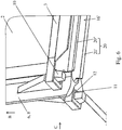
- the end edges 9' of the free ends 9 of the branches 8, 8 'of the U-shaped gasket 6 are located beyond the face 4 of the plate or cross support and fixing 3 carrying the linear joint 7 and are connected by abutment with the opposite ends 7 ', 7 "of said linear joint 7 (see Figures 4B , 6 and 7 ).
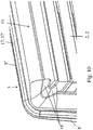
- each of the three constituent segments 8, 8 ', 8'"of the U-shaped gasket 6 is constituted, seen in cross-section, on the one hand, by a first part 15 bearing under pressure on the corresponding face 4 ', 4 ", 4'" opposite the body 2 'of the exchanger 2 and having two longitudinal flanges 15' and 15 "mutually divergent, preferably arcuate or curved in cross section, and forming with said faces 4 ' , 4 ", 4 '” channel portions 16 and, secondly, a second portion 17 bearing on the inner wall 1 "of the housing 1' of the exchanger 1 and having a longitudinal flexible contact formation 17 'cooperating sealingly with a flat surface portion, a groove 18 or ribs 18' of said inner wall 1 ".
- the seal in U 6 comprises, at the two corners connecting two by two the three constituent segments 8, 8 ', 8 "of its body 2', the lateral lips protruding and flexible 19, in the form of angles, coming in intimate support on the respectively corresponding corner of the body 2 'of the exchanger 2.
- the second part 17 of the gasket 6 has a section similar to the first part of the gasket 7.
- the free ends 9 of the branches 8 and 8 'of the body 6' of the U-shaped gasket 6 substantially close the opposite openings of the channel portion 16 'formed by the cooperation of the linear joint 7 with the inner wall 1 "of the housing 1 'of the distributor 1, the end edges 9' of said free ends 9 bearing on said inner wall 1".
- the body of the linear joint 7 is formed, on the one hand, of a first portion 20 bearing under pressure on the inner wall 1 "of the body 1 'of the housing 1 and having two mutually diverging longitudinal wings 20' and 20 ", preferably arched or curved in cross-section, and forming with said inner wall 1" a channel portion 16 ', and secondly a second flat portion 21 in surface contact with the crossmember or the support plate and fixing 3.
- the body 6 'of the U-shaped gasket 6 is made of a more flexible material, for example elastomer thermoplastic, than the constituent material of the linear joint 7, for example of unfilled polyamide 66.
- the housing 1 ' consists of two complementary component parts 22 and 22', namely an upper part 22 and a lower part 22 'assembled at respective cooperating edges, defining an assembly plane PA inclined relative to the plane of subdivision P, preferably perpendicular to the latter, the lower housing portion 22 'having attachment sites for the plate or the cross support and fixing 3.
- the housing 1 ' is made of plastic material, preferably by sealing assembly of two parts 22 and 22' in the form of half-shells of thermoplastic material.
- the invention also relates to a motor vehicle with internal combustion engine, supercharged or not, with or without an EGR gas recirculation circuit and having an air intake system with a supercharged intake manifold or intake manifold.
- This vehicle is characterized in that the distributor is a distributor 1 as described above, constituting a multifunctional module integrating in the enclosure of its housing 1 'at least one heat exchanger 2 in the tubes, fins or the like of the body 2 'which circulates air supercharged.
- the invention also relates to a method of manufacturing a splitter as described above.
- This method consists in providing the two constituent parts 22 and 22 'of a distributor housing 1' 1, a heat exchanger 2 provided with a support and fixing plate 3, a U-shaped gasket 6 and a linear joint 7 , to mount the two seals 6 and 7 on the body 2 'of the exchanger 2, by locking their assembly by engagement or clipping and so as to form a peripheral seal around said body 2', to arrange the exchanger 2 thus equipped in the lower part 22 'of the housing 1' of the distributor 1 and to secure said plate 3 at the fixing sites of this lower part 22 'and, finally, to seal the upper part 22 with the lower part 22 ', for example by laser welding or by hot gas, by gluing or by mechanical joining, to constitute the housing 1' of the distributor 1.
Abstract
La présente invention concerne un répartiteur d'admission pour moteur à combustion interne comprenant un échangeur (2) de chaleur intégré. Cet échangeur (2) comporte une plaque support assurant son montage rigide dans le répartiteur et des moyens (6, 7) d'étanchéité périphériques formant une barrière étanche circonférentielle sensiblement continue entre l'échangeur (2) et le répartiteur (1), divisant périphériquement le volume interstitiel (5) en deux. Répartiteur (1) caractérisé en ce que le plan (P) de subdivision du volume interstitiel (5) est perpendiculaire par rapport au plan de la plaque support (3) et en ce que les moyens d'étanchéité périphériques sont constitués par deux composantes complémentaires (6 et 7) reliées entre elles et solidarisées avec l'échangeur (2).The present invention relates to an intake manifold for an internal combustion engine comprising an integrated heat exchanger (2). This exchanger (2) comprises a support plate ensuring its rigid mounting in the tundish and peripheral sealing means (6, 7) forming a substantially continuous circumferential sealing barrier between the exchanger (2) and the tundish (1), dividing peripherally the interstitial volume (5) in two. Dispatcher (1) characterized in that the plane (P) of subdivision of the interstitial volume (5) is perpendicular to the plane of the support plate (3) and in that the peripheral sealing means consist of two complementary components (6 and 7) interconnected and secured to the exchanger (2).
Description
La présente invention concerne le domaine des équipements techniques des véhicules automobiles à moteur à combustion interne, plus particulièrement les éléments et composants formant la ligne d'admission des gaz comburants de ces moteurs.The present invention relates to the field of technical equipment of motor vehicles with internal combustion engine, more particularly the elements and components forming the intake line of the oxidizing gases of these engines.
L'invention a, dans ce contexte, pour objet un répartiteur ou collecteur d'admission intégrant un échangeur de chaleur.The invention, in this context, relates to a distributor or intake manifold incorporating a heat exchanger.
De très nombreuses réalisations de répartition ou collecteurs d'admission sont connues dans l'état de la technique. Il en est de même pour les échangeurs de chaleur, en particulier ceux destinés à refroidir l'air suralimenté ou encore ceux destinés à refroidir les gaz EGR avant leur mélange avec l'air frais, en vue de l'injection du mélange gazeux résultant dans les cylindres.Very many embodiments of distribution or intake manifolds are known in the state of the art. It is the same for heat exchangers, in particular those intended to cool the supercharged air or those intended to cool the EGR gases before they are mixed with the fresh air, with a view to the injection of the gaseous mixture resulting in the cylinders.
Une demande constante, voire une contrainte constructive permanente, dans le domaine de la fabrication automobile, est le gain de place en particulier sous le capot et dans l'environnement du moteur.A constant demand, or even a permanent constructive constraint, in the field of automobile manufacturing, is the saving of space, particularly under the hood and in the engine environment.
Dans le cadre de cette problématique générale, une tendance forte vise l'intégration de plusieurs fonctions complémentaires, associées et/ou consécutives dans un même module ou une même unité structurel(le).In the context of this general problematic, a strong tendency is the integration of several complementary, associated and / or consecutive functions in the same module or the same structural unit (the).
Ainsi, il a été proposé depuis plusieurs années de combiner les fonctions "répartiteur d'admission" et "échangeur de chaleur" dans un même module et différentes solutions de réalisation de ce type de module unitaire et multifonctionnel sont déjà connues.Thus, it has been proposed for several years to combine the functions "inlet distributor" and "heat exchanger" in the same module and different solutions for producing this type of unitary and multifunctional module are already known.
Dans l'état de la technique sont notamment connus des répartiteurs d'admission pour moteur à combustion interne intégrant au moins un échangeur de chaleur monté dans le volume intérieur dudit collecteur, c'est-à-dire encapsulé hermétiquement.In the state of the art are known in particular intake manifolds for internal combustion engine incorporating at least one heat exchanger mounted in the interior volume of said collector, that is to say, hermetically encapsulated.
Il en résulte que ledit volume intérieur est séparé en deux compartiments situés de part et d'autre dudit échangeur, et que le flux de gaz circulant dans le collecteur traverse ledit échangeur pour passer d'un premier desdits compartiments vers le second compartiment.As a result, said interior volume is separated into two compartments located on either side of said exchanger, and that the flow of gas flowing in the collector passes through said exchanger to pass from a first of said compartments to the second compartment.
Deux problèmes majeurs se posent dans ce type de construction composite (module combiné : répartiteur + échangeur intégré), à savoir, le maintien rigide de l'échangeur dans le corps du répartiteur et la nécessité d'étanchéifier l'interface périphérique entre l'échangeur et le corps du répartiteur (volume interstitiel), afin de forcer le flux gazeux à traverser l'échangeur (c'est-à-dire traverser la formation ou le faisceau de tubes ou d'ailettes dans lesquel(le)s circule le flux gazeux à refroidir en circulant autour et entre ces tubes ou ailettes) et ainsi optimiser l'action de ce dernier.Two major problems arise in this type of composite construction (combined module: distributor + integrated heat exchanger), namely, the rigid holding of the exchanger in the body of the distributor and the need to seal the peripheral interface between the exchanger and the body of distributor (interstitial volume), in order to force the gas flow through the exchanger (that is to say through the formation or bundle of tubes or fins in which the gas flow to be cooled to circulating around and between these tubes or fins) and thus optimize the action of the latter.
Conformément à un premier mode de réalisation connu de collecteurs d'admission formant modules combinés, par exemple illustrés par les documents
Dans ce premier type de réalisation, les parties fonctionnelles de l'échangeur sont assemblées avec les parois du collecteur en réalisant une double étanchéité, à savoir l'étanchéité de l'échangeur lui-même et l'étanchéité de ce dernier vis-à-vis du collecteur.In this first type of embodiment, the functional parts of the exchanger are assembled with the walls of the collector by providing a double seal, namely the sealing of the exchanger itself and the sealing of the latter vis-à- collector screw.
Il en résulte une complexité de construction et des contraintes de fabrication et de montage très élevées, résultant en un coût de revient important.This results in a complexity of construction and manufacturing and assembly constraints very high, resulting in a significant cost.
En accord avec un second mode de réalisation connu, par exemple du document
Néanmoins, l'opération d'assemblage est délicate à réaliser et des contraintes importantes agissent sur le plan d'assemblage (réalisation d'une fixation mécanique et d'une double étanchéité au niveau de ce plan).Nevertheless, the assembly operation is difficult to perform and significant stresses act on the assembly plane (realization of a mechanical attachment and a double seal at this plane).
Selon un troisième mode de réalisation connu, l'échangeur de chaleur est réalisé séparément puis monté dans le corps du répartiteur lorsque ce dernier est déjà en grande partie assemblé (cf.
Par ailleurs, sont également connues différentes réalisations de moyens d'étanchéité périphériques autour de l'échangeur (barrière étanche entre les faces extérieures de l'échangeur et la paroi interne du boîtier du répartiteur).Furthermore, various embodiments of peripheral sealing means around the exchanger are also known (sealed barrier between the outer faces of the exchanger and the inner wall of the splitter box).
Ainsi, les documents
Enfin, par le document
La présente invention a pour but de proposer une solution constructive de répartiteur intégrant un échangeur, dans laquelle les fonctions de montage et d'étanchéité périphérique autour de l'échangeur sont différenciées structurellement et spatialement, tout en fournissant une étanchéité s'adaptant aux variations dimensionnelles différenciées de l'échangeur et du répartiteur (coefficients de dilatation thermiques différents), facile et rapide à monter, pouvant éventuellement être réalisée en plusieurs matériaux adaptés au lieu d'implantation et pouvant avantageusement être assemblée de manière résistante et précise avec l'échangeur, avant même son montage dans le répartiteur.The object of the present invention is to propose a constructive solution of a distributor integrating an exchanger, in which the assembly and peripheral sealing functions around the exchanger are differentiated structurally and spatially, while providing a seal adapting to dimensional variations. differentiated from the exchanger and the distributor (different thermal expansion coefficients), easy and quick to assemble, possibly being made of several materials adapted to the location and can advantageously be assembled in a resistant and precise manner with the exchanger, even before it is mounted in the splitter box.
De plus, l'échangeur intégré structurellement dans le répartiteur ne devrait pas être tributaire d'un support de montage formant également couvercle de fermeture pour le boitier du répartiteur, de manière à permettre un montage plus flexible dans ce dernier.In addition, the heat exchanger structurally integrated into the distribution frame should not be dependent on a mounting bracket which also forms a closing cover for the distribution box, so as to allow a more flexible mounting therein.
A cet effet l'invention a pour objet un répartiteur ou collecteur d'admission pour moteur à combustion interne, en particulier un répartiteur d'admission d'air suralimenté, comprenant un échangeur de chaleur dont le corps a une forme générale parallélépipédique, qui est monté dans le boîtier du dit répartiteur et qui est destiné à être exposé au flux gazeux traversant ledit boîtier,
ledit échangeur comportant ou étant solidaire d'une plaque ou d'une traverse de support et de fixation, rapportée sur ou formant une face du corps de l'échangeur et assurant son montage rigide dans ce boîtier,
ledit échangeur étant positionné dans ledit boîtier avec formation d'un volume interstitiel entre eux, enveloppant sensiblement le corps dudit échangeur, et des moyens d'étanchéité périphériques étant rapportés sur le corps de l'échangeur et sur la plaque ou traverse de support et de fixation de manière à former une barrière étanche circonférentielle sensiblement continue entre ces derniers et le boîtier du répartiteur, divisant périphériquement le volume interstitiel en deux, avantageusement selon un plan sensiblement perpendiculaire à la direction de circulation du flux gazeux traversant ledit échangeur,
répartiteur caractérisé
en ce que le plan de subdivision du volume interstitiel est distinct du plan principal de la plaque ou de la traverse de support et de fixation, et avantageusement incliné et préférentiellement sensiblement perpendiculaire par rapport à ce dernier, et
en ce que les moyens d'étanchéité périphériques sont constitués par deux composantes complémentaires reliées entre elles et solidarisées avec l'échangeur, à savoir, une première composante sous la forme d'un joint en U rapporté sur les trois faces du corps de l'échangeur non associées à la traverse ou à la plaque de support et de fixation, et une seconde composante sous la forme d'un joint sensiblement linéaire rapporté sur la face associée à ladite traverse ou plaque, ledit joint sensiblement linéaire étant assemblé mécaniquement, au niveau de ses deux extrémités longitudinales opposées, aux extrémités libres des deux branches du joint en U.To this end, the subject of the invention is an intake manifold or manifold for an internal combustion engine, in particular a supercharged intake air distributor, comprising a heat exchanger whose body has a generally parallelepipedal shape, which is mounted in the housing said distributor and which is intended to be exposed to the gas flow passing through said housing,
said exchanger comprising or being integral with a plate or a cross support and fixing, attached to or forming a face of the body of the exchanger and ensuring its rigid mounting in this housing,
said exchanger being positioned in said casing with the formation of an interstitial volume between them, substantially enveloping the body of said exchanger, and peripheral sealing means being attached to the body of the exchanger and to the support plate and fastening so as to form a substantially continuous circumferential sealing barrier between the latter and the splitter box, dividing peripherally the interstitial volume in two, advantageously in a plane substantially perpendicular to the flow direction of the gas flow passing through said exchanger,
distributor characterized
in that the plane of subdivision of the interstitial volume is distinct from the main plane of the support and fastening plate or crossbar, and advantageously inclined and preferably substantially perpendicular to the latter, and
in that the peripheral sealing means consist of two complementary components connected to each other and secured to the exchanger, namely, a first component in the form of a U-shaped gasket attached to the three faces of the body of the exchanger not associated with the crossbar or the support and fixing plate, and a second component in the form of a substantially linear seal attached to the face associated with said crossmember or plate, said substantially linear seal being mechanically assembled at the of its two opposite longitudinal ends, at the free ends of the two branches of the U-joint.
L'invention sera mieux comprise, grâce à la description ci-après, qui se rapporte à des modes de réalisation préférés, donnés à titre d'exemples non limitatifs, et expliqués avec référence aux dessins schématiques annexés, dans lesquels :
- la
figure 1 est une vue éclatée en perspective d'un répartiteur d'admission intégrant un échangeur de chaleur, pour former un module multifonctionnel selon un mode de réalisation préféré de l'invention ; - la
figure 2 est une vue en élévation et en coupe, selon un plan perpendiculaire au plan contenant les moyens d'étanchéité périphériques formés par un joint en U et un joint linéaire, du répartiteur de lafigure 1 à l'état assemblé ; - la
figure 3 est une vue en perspective d'un échangeur thermique tel que ressortant desfigures 1 et2 , avant montage des moyens d'étanchéité périphérique ; - les
figures 4A et4B sont des vues en perspective de l'échangeur de lafigure 3 , les moyens d'étanchéité périphériques étant en place ; - la
figure 5 est une vue partielle de la partie inférieure de l'objet représentéfigure 3 ; - la
figure 6 est une vue du détail A de lafigure 4B , à une échelle différente ; - la
figure 7A est une vue partielle et en perspective de dessous de l'objet de lafigure 6 , le joint linéaire inférieur n'étant pas représenté ; - la
figure 7B est une vue partielle de dessous, suivant la direction B de l'objet de lafigure 6 ; - la
figure 7C est une vue latérale partielle, suivant la direction C de l'objet de lafigure 6 , la partie inférieure du joint en U étant enlevée ; - la
figure 8 est une vue partielle du détail D de l'objet de lafigure 2 ; - les
figures 9A à 9C sont des vues similaires à celles de lafigure 8 , illustrant la mise en oeuvre de variantes constructives du joint périphérique ; - la
figure 10 est une vue du détail E de lafigure 4A , à une échelle différente ; - la
figure 11 est une vue similaire à celle de lafigure 10 du joint seul, et, - la
figure 12 est une vue du détail G de lafigure 3 , à une échelle différente.
- the
figure 1 is an exploded perspective view of an intake manifold integrating a heat exchanger, to form a multifunctional module according to a preferred embodiment of the invention; - the
figure 2 is an elevation view in section, in a plane perpendicular to the plane containing the peripheral sealing means formed by a U-shaped joint and a linear joint, of the distributor of thefigure 1 in the assembled state; - the
figure 3 is a perspective view of a heat exchanger such asfigures 1 and2 , before mounting the peripheral sealing means; - the
Figures 4A and4B are perspective views of the exchanger of thefigure 3 the peripheral sealing means being in place; - the
figure 5 is a partial view of the lower part of the object shownfigure 3 ; - the
figure 6 is a detail view A of theFigure 4B , on a different scale; - the
Figure 7A is a partial and perspective view from below of the object of thefigure 6 the lower linear joint is not shown; - the
Figure 7B is a partial view from below, following the B direction of the object of thefigure 6 ; - the
Figure 7C is a partial side view, following the direction C of the object of thefigure 6 the lower part of the U-shaped gasket being removed; - the
figure 8 is a partial view of the detail D of the object of thefigure 2 ; - the
Figures 9A to 9C are views similar to those of thefigure 8 , illustrating the implementation of constructive variants of the peripheral seal; - the
figure 10 is a detail view E of theFigure 4A , on a different scale; - the
figure 11 is a view similar to that of thefigure 10 seal alone, and, - the
figure 12 is a detail view G of thefigure 3 , on a different scale.
Les
Cet échangeur 2 comporte ou est solidaire d'une plaque ou d'une traverse 3 de support et de fixation, rapportée sur ou formant une face 4 du corps 2' de l'échangeur 2 et assurant son montage rigide dans ce boîtier 1'.This
Cet échangeur 2 est positionné dans ledit boîtier 1' avec formation d'un volume interstitiel 5 entre eux, entourant sensiblement le corps 2' dudit échangeur 2, et des moyens 6, 7 d'étanchéité périphériques sont rapportés sur le corps 2' de l'échangeur 2 et sur la plaque ou traverse de support et de fixation 3 de manière à former une barrière étanche circonférentielle sensiblement continue entre ces derniers et le boîtier 1' du répartiteur 1, divisant périphériquement le volume interstitiel 5 en deux, avantageusement selon un plan P sensiblement perpendiculaire à la direction de circulation du flux gazeux F traversant ledit échangeur 2.This
Le boitier 1' peut, par exemple, être formé par l'assemblage des deux parties (inférieure 22 et supérieure 22') en forme de coques (
Conformément à l'invention, il est prévu que le plan P de subdivision du volume interstitiel 5 est distinct du plan principal de la plaque ou de la traverse de support et de fixation 3, et avantageusement incliné et préférentiellement sensiblement perpendiculaire par rapport à ce dernier.According to the invention, provision is made for the subdivision plane P of the
De plus, les moyens d'étanchéité périphériques sont constitués par deux composantes complémentaires 6 et 7 reliées entre elles et solidarisées avec l'échangeur 2, à savoir, une première composante 6 sous la forme d'un joint en U rapporté sur les trois faces 4', 4", 4'" du corps 2' de l'échangeur 2 non associées à la traverse ou à la plaque de support et de fixation 3, et une seconde composante 7 sous la forme d'un joint sensiblement linéaire rapporté sur la face 4 associée à ladite traverse ou plaque 3, ledit joint sensiblement linéaire 7 étant aboutant et assemblé mécaniquement, au niveau de ses deux extrémités longitudinales opposées 7', 7", avec les extrémités libres 9 des deux branches 8, 8' du joint en U 6.In addition, the peripheral sealing means are constituted by two
Grâce à ces dispositions, les fonctions de montage et d'étanchéisation périphérique de l'échangeur sont clairement différenciées et désaccouplées entre elles et une étanchéité est fournie au niveau des quatre faces ou cotés périphériques de l'échangeur 2 situé(e)s en regard de la paroi interne 1" du boitier 1' le recevant.Thanks to these provisions, the assembly and sealing functions of the exchanger are clearly differentiated and uncoupled from each other and a seal is provided at the four faces or peripheral sides of the
En outre, une constitution en deux parties de l'étanchéité périphérique continue 6, 7 autorise une fabrication et un montage aisés, tout en limitant le nombre de composantes élémentaires à assembler et à prémonter sur l'échangeur 2 avant son installation dans ledit boitier 1'.In addition, a two-part constitution of the continuous
Cette décomposition constructive de l'étanchéité périphérique continue permet également, compte tenu notamment du placement orienté de l'échangeur 2 dans le répartiteur 1, avec définition d'un côté supérieur et d'un côté inférieur, de mettre en oeuvre le cas échéant un profil de joint différent au niveau de ce côté inférieur, sous la plaque ou traverse support 3, plus adapté à cette région.This constructive decomposition of the continuous peripheral sealing also makes it possible, particularly in view of the oriented placement of the
Les profils des joints en U 6 et linéaire 7 sont bien entendu adaptés pour assurer l'étanchéité malgré les tolérances de fabrication et les dilatations thermiques ou sous pression du corps 2' de l'échangeur 2 et du boitier 1' du répartiteur 1.The profiles of U-shaped and
En vue de faciliter leur liaisonnement, sans mise en oeuvre de pièce additionnelle ou d'outils ou de procédé technologique particulier, les deux joints sont préférentiellement assemblés mutuellement, au niveau de leur deux zones de liaisonnement, par des moyens complémentaires d'assemblage 10, 11, coopérants entre eux par engagement mécanique avec enclenchement, clippage ou verrouillage élastique.In order to facilitate their bonding, without implementation of additional parts or tools or particular technological process, the two seals are preferably assembled mutually, at their two bonding zones, by complementary assembly means 10, 11, cooperating with each other by mechanical engagement with engagement, clipping or elastic locking.
Avantageusement, le joint en U 6 comporte, au niveau des extrémités libres 9 des deux branches 8, 8' du corps 6' en U, des crans, des crochets, des harpons ou des formations proéminentes accrochantes analogues 10, et le joint linéaire 7 comporte à ses deux extrémités opposées 7' et 7" des sites d'accrochage 11 latéralement saillants, en particulier des anses, des oeillets ou des formations ajourées analogues, aptes et destinés à recevoir les formations proéminentes 10 des extrémités 9 du joint en U 6 pour réaliser par coopération mutuelle des liaisons mécaniques verrouillées.Advantageously, the
Afin d'autoriser un prémontage simple et sûr des joints 6 et 7 sur le corps 2' de l'échangeur 2, de regrouper géographiquement les sites de solidarisation et de pouvoir effectuer le cas échéant simultanément les opérations d'assemblage et de prémontage, les deux joints 6 et 7 formant les deux composantes des moyens d'étanchéité périphériques sont également reliées mécaniquement à la traverse ou plaque de support et de fixation 3, préférentiellement au niveau de leurs extrémités 7, 7", 9 mutuellement assemblées, le joint en U 6 étant avantageusement maintenu en appui sous pression contre les faces 4', 4", 4'" du corps 2 de l'échangeur 2 par le biais de cette liaison.In order to allow a simple and secure premounting of the
En accord avec un mode de réalisation constructive très préféré, ressortant notamment des
En vue d'assujettir l'étanchéité 6, 7 sur le corps 2' et éviter son déplacement, ledit 2' peut être pourvu, comme le montrent à titre d'exemple les
Ces moyens de calage peuvent, par exemple, consister en des ailes, des lèvres ou des languettes saillantes 13, 13', sous forme de prolongements ou de crevées dudit corps 2' ou de son enveloppe extérieure.These wedging means may, for example, consist of wings, lips or protruding
De manière similaire, il peut être prévu que la traverse ou la plaque de support et de fixation 3, d'une part, et le joint linéaire 7, d'autre part, sont pourvus de moyens 14, 14' mutuellement coopérants d'indexation, et éventuellement de solidarisation, tels que par exemple des couples [ergot 14 / orifice borgne 14'] (voir
Afin d'assurer une continuité d'étanchéité au niveau des zones de coins ou d'angles inférieurs du corps 2' de l'échangeur 2, les bords terminaux 9' des extrémités libres 9 des branches 8, 8' du joint en U 6 sont situées au-delà de la face 4 de la plaque ou traverse de support et de fixation 3 portant le joint linéaire 7 et se raccordent par aboutement avec les extrémités opposées 7', 7" dudit joint linéaire 7 (voir
Préférentiellement, et comme l'illustrent les
Pour garantir l'étanchéité au niveau des régions angulaires reliant les faces latérales 4' et 4'" à la face supérieure 4" de l'échangeur 2, et s'adapter aux dispersivités constructives de ce dernier, il peut être prévu que le joint en U 6 comporte, au niveau des deux coins reliant deux à deux les trois segments constitutifs 8, 8', 8" de son corps 2', des lèvres latérales saillantes et souples 19, en forme de cornières, venant en appui intime sur le coin respectivement correspondant du corps 2' de l'échangeur 2.To guarantee the tightness at the angular regions connecting the side faces 4 'and 4' "to the
Avantageusement, la seconde partie 17 du joint 6 présente une section similaire à la première partie du 20 du joint 7.Advantageously, the
A tout le moins, il peut être prévu que les extrémités libres 9 des branches 8 et 8' du corps 6' du joint en U 6 obturent sensiblement les ouvertures opposées de la portion de canal 16' formée par la coopération du joint linéaire 7 avec la paroi interne 1" du boîtier 1' du répartiteur 1, les bords terminaux 9' desdites extrémités libres 9 venant en appui sur ladite paroi interne 1".At the very least, it can be provided that the free ends 9 of the
Avantageusement, le corps du joint linéaire 7 est constitué, d'une part, d'une première partie 20 venant en appui sous pression sur la paroi interne 1" du corps 1' du boîtier 1 et comportant deux ailes longitudinales mutuellement divergentes 20' et 20", préférentiellement arquées ou courbes en section transversale, et formant avec ladite paroi interne 1" une portion de canal 16', et, d'autre part, une seconde partie plane 21 en contact surfacique avec la traverse ou la plaque de support et de fixation 3.Advantageously, the body of the linear joint 7 is formed, on the one hand, of a
Compte tenu de leurs positionnements de leurs rôles distincts, le corps 6' du joint en U 6 est réalisé en un matériau plus flexible, par exemple du thermoplastique élastomère, que le matériau constitutif du joint linéaire 7, par exemple en polyamide 66 non chargé.Given their positioning of their distinct roles, the body 6 'of the
En accord avec une construction pratique préférée, ressortant des
Avantageusement, le boîtier 1' est réalisé en matériau plastique, préférentiellement par assemblage étanche de deux parties 22 et 22' en forme de demi-coques en matériau thermoplastique.Advantageously, the housing 1 'is made of plastic material, preferably by sealing assembly of two
L'invention concerne également un véhicule automobile à moteur à combustion interne, suralimenté ou non, comprenant ou non un circuit de recirculation des gaz EGR et comportant un système d'admission d'air avec un répartiteur ou collecteur d'admission d'air suralimenté. Ce véhicule est caractérisé en ce que le répartiteur est un répartiteur 1 tel que décrit ci-dessus, constituant un module multifonctionnel intégrant dans l'enceinte de son boîtier 1' au moins un échangeur de chaleur 2 dans les tubes, ailettes ou analogue du corps 2' duquel circule de l'air suralimenté.The invention also relates to a motor vehicle with internal combustion engine, supercharged or not, with or without an EGR gas recirculation circuit and having an air intake system with a supercharged intake manifold or intake manifold. . This vehicle is characterized in that the distributor is a
Enfin, l'invention porte également sur un procédé de fabrication d'un répartiteur tel que décrit précédemment.Finally, the invention also relates to a method of manufacturing a splitter as described above.
Ce procédé consiste à fournir les deux parties constitutives 22 et 22' d'un boîtier 1' de répartiteur 1, un échangeur de chaleur 2 pourvue d'une plaque 3 de support et de fixation, un joint en U 6 et un joint linéaire 7, à monter les deux joints 6 et 7 sur le corps 2' de l'échangeur 2, en verrouillant leur montage par enclenchement ou clippage et de manière à constituer une garniture d'étanchéité périphérique autour dudit corps 2', à disposer l'échangeur 2 ainsi équipé dans la partie inférieure 22' du boîtier 1' du répartiteur 1 et à solidariser ladite plaque 3 à des sites de fixation de cette partie inférieure 22' et, enfin, à assembler de manière étanche la partie supérieure 22 avec la partie inférieure 22', par exemple par soudage par laser ou par gaz chaud, par collage ou par solidarisation mécanique, pour constituer le boîtier 1' du répartiteur 1.This method consists in providing the two
Bien entendu, l'invention n'est pas limitée aux modes de réalisation décrits et représentés aux dessins annexés. Des modifications restent possibles, notamment du point de vue de la constitution des divers éléments ou par substitution d'équivalents techniques, sans sortir pour autant du domaine de protection de l'invention.Of course, the invention is not limited to the embodiments described and shown in the accompanying drawings. Modifications are possible, particularly from the point of view of the constitution of the various elements or by substitution of technical equivalents, without departing from the scope of protection of the invention.
Claims (17)
ledit échangeur (2) comportant ou étant solidaire d'une plaque ou d'une traverse (3) de support et de fixation, rapportée sur ou formant une face (4) du corps (2') de l'échangeur (2) et assurant son montage rigide dans ce boîtier (1'),
ledit échangeur (2) étant positionné dans ledit boîtier (1') avec formation d'un volume interstitiel (5) entre eux, entourant sensiblement le corps (2') dudit échangeur (2), et des moyens (6, 7) d'étanchéité périphériques étant rapportés sur le corps (2') de l'échangeur (2) et sur la plaque ou traverse de support et de fixation (3) de manière à former une barrière étanche circonférentielle sensiblement continue entre ces derniers et le boîtier (1') du répartiteur (1), divisant périphériquement le volume interstitiel (5) en deux, avantageusement selon un plan (P) sensiblement perpendiculaire à la direction de circulation du flux gazeux (F) traversant ledit échangeur (2),
répartiteur (1) caractérisé
en ce que le plan (P) de subdivision du volume interstitiel (5) est distinct du plan principal de la plaque ou de la traverse de support et de fixation (3), et avantageusement incliné et préférentiellement sensiblement perpendiculaire par rapport à ce dernier, et
en ce que les moyens d'étanchéité périphériques sont constitués par deux composantes complémentaires (6 et 7) reliées entre elles et solidarisées avec l'échangeur (2), à savoir, une première composante (6) sous la forme d'un joint en U rapporté sur les trois faces (4', 4", 4'") du corps (2') de l'échangeur (2) non associées à la traverse ou à la plaque de support et de fixation (3), et une seconde composante (7) sous la forme d'un joint sensiblement linéaire rapporté sur la face (4) associée à ladite traverse ou plaque (3), ledit joint sensiblement linéaire (7) étant aboutant et assemblé mécaniquement, au niveau de ses deux extrémités longitudinales opposées (7', 7"), avec les extrémités libres (9) des deux branches (8, 8') du joint en U (6).Intake manifold or intake manifold for an internal combustion engine, in particular a supercharged air intake manifold, comprising a heat exchanger (2) whose body (2 ') has a generally parallelepipedal shape, which is mounted in the housing (1 ') of said distributor (1) and which is intended to be exposed to the gas flow (F) passing through said housing (1'),
said exchanger (2) comprising or being integral with a plate or a crosspiece (3) for support and attachment, attached to or forming a face (4) of the body (2 ') of the exchanger (2) and ensuring its rigid mounting in this housing (1 '),
said exchanger (2) being positioned in said housing (1 ') with the formation of an interstitial volume (5) between them, substantially surrounding the body (2') of said exchanger (2), and means (6, 7) of sealing devices being attached to the body (2 ') of the exchanger (2) and to the support and fixing plate (3) so as to form a substantially continuous circumferential sealing barrier between the latter and the housing ( 1 ') of the distributor (1), dividing peripherally the interstitial volume (5) in two, advantageously along a plane (P) substantially perpendicular to the flow direction of the gas flow (F) passing through said exchanger (2),
distributor (1) characterized
in that the plane (P) of subdivision of the interstitial volume (5) is distinct from the main plane of the support and fixing plate (3), and advantageously inclined and preferably substantially perpendicular to the latter, and
in that the peripheral sealing means consist of two complementary components (6 and 7) interconnected and secured to the exchanger (2), namely, a first component (6) in the form of a gasket U attached to the three faces (4 ', 4 ", 4'") of the body (2 ') of the exchanger (2) not associated with the crossbar or the support and fixing plate (3), and a second component (7) in the form of a substantially linear seal attached to the face (4) associated with said crossmember or plate (3), said substantially linear joint (7) being abutting and mechanically assembled at its two ends opposite longitudinal (7 ', 7 "), with the free ends (9) of the two legs (8, 8') of the U-joint (6).
Applications Claiming Priority (1)
| Application Number | Priority Date | Filing Date | Title |
|---|---|---|---|
| FR1662046A FR3059727B1 (en) | 2016-12-07 | 2016-12-07 | INTAKE DISTRIBUTOR WITH AN INTEGRATED HEAT EXCHANGER |
Publications (2)
| Publication Number | Publication Date |
|---|---|
| EP3333406A1 true EP3333406A1 (en) | 2018-06-13 |
| EP3333406B1 EP3333406B1 (en) | 2021-02-17 |
Family
ID=58501497
Family Applications (1)
| Application Number | Title | Priority Date | Filing Date |
|---|---|---|---|
| EP17205504.8A Active EP3333406B1 (en) | 2016-12-07 | 2017-12-05 | Intake manifold with built-in heat exchanger |
Country Status (4)
| Country | Link |
|---|---|
| US (1) | US10400718B2 (en) |
| EP (1) | EP3333406B1 (en) |
| CN (1) | CN108167061B (en) |
| FR (1) | FR3059727B1 (en) |
Families Citing this family (1)
| Publication number | Priority date | Publication date | Assignee | Title |
|---|---|---|---|---|
| FR3090845B1 (en) * | 2018-12-19 | 2021-01-08 | Valeo Systemes Thermiques | Motor vehicle heat exchanger sealing device |
Citations (6)
| Publication number | Priority date | Publication date | Assignee | Title |
|---|---|---|---|---|
| EP0578916A2 (en) * | 1992-07-16 | 1994-01-19 | Längerer & Reich GmbH & Co. | Heat-exchanger |
| DE102008061759A1 (en) * | 2008-12-12 | 2010-06-17 | Behr Gmbh & Co. Kg | Suction tube housing, has seal comprising with four shanks resting against housing wall and block wall such that two angle areas are subjected with working medium, so that shanks are pressed by working medium |
| DE102009049455A1 (en) * | 2009-10-14 | 2011-04-21 | Draftex Automotive Gmbh | Sealing profile for e.g. mobile body parts of cabriolet, has detent area engaged into detent retainer of mobile body part and made of thermoplastic material e.g. thermoplastic elastomer, and seal area made of synthetic rubber |
| EP2706209A1 (en) * | 2012-09-06 | 2014-03-12 | Systèmes Moteurs (Société par Actions Simplifiée) | Method for producing an intake manifold integrating a heat exchanger and corresponding intake manifold |
| DE102013006956A1 (en) * | 2013-04-23 | 2014-10-23 | Modine Manufacturing Co. | Air-conducting component with a charge air cooler |
| WO2015149951A1 (en) * | 2014-04-04 | 2015-10-08 | Valeo Systemes Thermiques | Heat exchanger for a motor vehicle |
Family Cites Families (17)
| Publication number | Priority date | Publication date | Assignee | Title |
|---|---|---|---|---|
| DE2546628A1 (en) | 1975-10-15 | 1977-04-28 | Euratom | SEALING SYSTEM FOR HIGH PRESSURE AND VACUUM |
| FR2645209B1 (en) | 1989-03-28 | 1991-07-19 | Ecia Equip Composants Ind Auto | COMPACT HEAT EXCHANGER-GAS DISTRIBUTOR DEVICE, IN PARTICULAR FOR A COMPRESSED HEAT ENGINE |
| JP4565372B2 (en) * | 2001-04-10 | 2010-10-20 | 本田技研工業株式会社 | Intercooler |
| FR2908832B1 (en) | 2006-11-20 | 2011-08-26 | Valeo Systemes Thermiques | CARTER FOR HEAT EXCHANGER |
| FR2908833B1 (en) | 2006-11-20 | 2011-06-17 | Valeo Sys Controle Moteur Sas | GAS ADMISSION DEVICE |
| DE102007030464A1 (en) | 2007-06-29 | 2009-01-08 | Volkswagen Ag | Suction tube for an internal combustion engine |
| DE102007040661A1 (en) * | 2007-08-27 | 2009-03-05 | Behr Gmbh & Co. Kg | Suction tube for an internal combustion engine |
| DE202007012231U1 (en) | 2007-08-31 | 2009-01-08 | Mann+Hummel Gmbh | Intake device intercooler unit for an internal combustion engine |
| FR2936572B1 (en) | 2008-09-30 | 2013-03-29 | Valeo Systemes Thermiques | SUPPORT DEVICE FOR AN EXCHANGE BEAM OF A HEAT EXCHANGER AND HEAT EXCHANGER HAVING SUCH A DEVICE |
| DE102009050258B3 (en) | 2009-10-21 | 2010-11-18 | Mann + Hummel Gmbh | Intake manifold for internal combustion engine, particularly for motor vehicle, has coolant intercooler arranged at opposite end of cooling fluid boxes |
| DE102009053884A1 (en) | 2009-11-20 | 2011-06-01 | Behr Gmbh & Co. Kg | Suction tube for an internal combustion engine |
| FR2953255B1 (en) | 2009-11-27 | 2012-10-12 | Valeo Systemes Thermiques | GAS SUPPLY MODULE OF A MOTOR VEHICLE ENGINE, ASSEMBLY OF A CYLINDER HEAD OF AN ENGINE AND SUCH A MODULE, AND MOTOR VEHICLE COMPRISING SUCH AN ASSEMBLY |
| FR2975765B1 (en) | 2011-05-26 | 2016-01-29 | Valeo Systemes Thermiques | THERMAL EXCHANGER, IN PARTICULAR FOR MOTOR VEHICLE, AND CORRESPONDING AIR INTAKE DEVICE |
| DE102012206121A1 (en) * | 2012-04-13 | 2013-10-17 | Behr Gmbh & Co. Kg | Arrangement of a charge air cooler in an intake manifold |
| DE102012213164A1 (en) * | 2012-07-26 | 2014-01-30 | Mahle International Gmbh | Fresh air supply system |
| FR2997178B1 (en) | 2012-10-19 | 2014-11-21 | Systemes Moteurs | HEAT EXCHANGER INTEGRATING DISTRIBUTOR AND METHOD FOR MANUFACTURING SAME |
| CN104863763A (en) * | 2015-05-27 | 2015-08-26 | 无锡开普动力有限公司 | Supercharging and inter-cooling structure of engine |
-
2016
- 2016-12-07 FR FR1662046A patent/FR3059727B1/en active Active
-
2017
- 2017-12-05 EP EP17205504.8A patent/EP3333406B1/en active Active
- 2017-12-07 CN CN201711281226.3A patent/CN108167061B/en active Active
- 2017-12-07 US US15/835,017 patent/US10400718B2/en active Active
Patent Citations (6)
| Publication number | Priority date | Publication date | Assignee | Title |
|---|---|---|---|---|
| EP0578916A2 (en) * | 1992-07-16 | 1994-01-19 | Längerer & Reich GmbH & Co. | Heat-exchanger |
| DE102008061759A1 (en) * | 2008-12-12 | 2010-06-17 | Behr Gmbh & Co. Kg | Suction tube housing, has seal comprising with four shanks resting against housing wall and block wall such that two angle areas are subjected with working medium, so that shanks are pressed by working medium |
| DE102009049455A1 (en) * | 2009-10-14 | 2011-04-21 | Draftex Automotive Gmbh | Sealing profile for e.g. mobile body parts of cabriolet, has detent area engaged into detent retainer of mobile body part and made of thermoplastic material e.g. thermoplastic elastomer, and seal area made of synthetic rubber |
| EP2706209A1 (en) * | 2012-09-06 | 2014-03-12 | Systèmes Moteurs (Société par Actions Simplifiée) | Method for producing an intake manifold integrating a heat exchanger and corresponding intake manifold |
| DE102013006956A1 (en) * | 2013-04-23 | 2014-10-23 | Modine Manufacturing Co. | Air-conducting component with a charge air cooler |
| WO2015149951A1 (en) * | 2014-04-04 | 2015-10-08 | Valeo Systemes Thermiques | Heat exchanger for a motor vehicle |
Also Published As
| Publication number | Publication date |
|---|---|
| US10400718B2 (en) | 2019-09-03 |
| CN108167061B (en) | 2021-10-19 |
| EP3333406B1 (en) | 2021-02-17 |
| FR3059727B1 (en) | 2019-12-13 |
| FR3059727A1 (en) | 2018-06-08 |
| US20180156170A1 (en) | 2018-06-07 |
| CN108167061A (en) | 2018-06-15 |
Similar Documents
| Publication | Publication Date | Title |
|---|---|---|
| EP2588782B1 (en) | Fluid valve | |
| EP1609640B1 (en) | Housing with a cover with gasket and locking element for a heating, ventilation and /or air conditioning installation for a passenger compartment | |
| WO2015149949A1 (en) | Heat exchanger for a motor vehicle | |
| EP3333406B1 (en) | Intake manifold with built-in heat exchanger | |
| FR2991038A1 (en) | HEAT EXCHANGER WITH REINFORCED COLLECTOR | |
| EP4072883A1 (en) | Cooling module for a motor vehicle | |
| EP2722517B2 (en) | Intake module in form of an intake manifold with integrated heat exchanger | |
| EP3491231B1 (en) | Intake manifold with integrated heat exchanger | |
| WO2011036410A1 (en) | Functional module including a distributor and a fuel rail, and production method thereof | |
| FR2918715A1 (en) | DOUBLE PLENUM ADMISSION COLLECTOR AND VEHICLE INCORPORATING SUCH A MANIFOLD | |
| EP2706209B1 (en) | Method for producing an intake manifold integrating a heat exchanger and corresponding intake manifold | |
| EP2722516B1 (en) | Intake manifold with integrated heat exchanger and its method of manufacturing | |
| FR3014031A1 (en) | LINK CONDUIT CONNECTING A THERMAL DEVICE OF A MOTOR VEHICLE TO THE APRON OF THE VEHICLE | |
| WO2021014090A1 (en) | Closing device and cooling module for a motor vehicle | |
| EP2622201A1 (en) | Functional air-supply module incorporating an injection set | |
| FR2873065A1 (en) | DEVICE FOR PROTECTING AN AIR PASSAGE OF A MOTOR VEHICLE WATER BOX AND CORRESPONDING BOX OF WATER | |
| FR3090842A1 (en) | Frame configured to support a heat exchanger | |
| EP3999732A1 (en) | Intake distributor made from plastic material with an at least partial inner lining | |
| FR3127560A1 (en) | Heat transfer fluid distribution structure | |
| FR3121653A1 (en) | AWNING GRID WITH FLOW LOCKING | |
| FR3102208A1 (en) | Cooling device | |
| WO2019180378A1 (en) | Intake air cooling device for an internal combustion engine | |
| FR3090531A1 (en) | Front panel module for motor vehicle | |
| FR3062600A1 (en) | COOLING UNIT FOR ENGINE COMPARTMENT | |
| FR3064054A1 (en) | EXTERMITE U-PLATE RADIATOR ORIENTED TO OUTSIDE, AND HEATING SYSTEM, VENTILATION OR AIR CONDITIONING THEREFOR |
Legal Events
| Date | Code | Title | Description |
|---|---|---|---|
| PUAI | Public reference made under article 153(3) epc to a published international application that has entered the european phase |
Free format text: ORIGINAL CODE: 0009012 |
|
| STAA | Information on the status of an ep patent application or granted ep patent |
Free format text: STATUS: THE APPLICATION HAS BEEN PUBLISHED |
|
| AK | Designated contracting states |
Kind code of ref document: A1 Designated state(s): AL AT BE BG CH CY CZ DE DK EE ES FI FR GB GR HR HU IE IS IT LI LT LU LV MC MK MT NL NO PL PT RO RS SE SI SK SM TR |
|
| AX | Request for extension of the european patent |
Extension state: BA ME |
|
| STAA | Information on the status of an ep patent application or granted ep patent |
Free format text: STATUS: REQUEST FOR EXAMINATION WAS MADE |
|
| 17P | Request for examination filed |
Effective date: 20181213 |
|
| RBV | Designated contracting states (corrected) |
Designated state(s): AL AT BE BG CH CY CZ DE DK EE ES FI FR GB GR HR HU IE IS IT LI LT LU LV MC MK MT NL NO PL PT RO RS SE SI SK SM TR |
|
| STAA | Information on the status of an ep patent application or granted ep patent |
Free format text: STATUS: EXAMINATION IS IN PROGRESS |
|
| 17Q | First examination report despatched |
Effective date: 20200121 |
|
| GRAP | Despatch of communication of intention to grant a patent |
Free format text: ORIGINAL CODE: EPIDOSNIGR1 |
|
| STAA | Information on the status of an ep patent application or granted ep patent |
Free format text: STATUS: GRANT OF PATENT IS INTENDED |
|
| RIC1 | Information provided on ipc code assigned before grant |
Ipc: F16J 15/02 20060101ALI20200909BHEP Ipc: F02M 35/104 20060101ALI20200909BHEP Ipc: F02M 35/10 20060101AFI20200909BHEP Ipc: F28F 9/007 20060101ALI20200909BHEP Ipc: F28F 9/04 20060101ALI20200909BHEP Ipc: F02B 29/04 20060101ALI20200909BHEP Ipc: F28F 9/00 20060101ALI20200909BHEP |
|
| INTG | Intention to grant announced |
Effective date: 20200923 |
|
| GRAS | Grant fee paid |
Free format text: ORIGINAL CODE: EPIDOSNIGR3 |
|
| GRAA | (expected) grant |
Free format text: ORIGINAL CODE: 0009210 |
|
| STAA | Information on the status of an ep patent application or granted ep patent |
Free format text: STATUS: THE PATENT HAS BEEN GRANTED |
|
| AK | Designated contracting states |
Kind code of ref document: B1 Designated state(s): AL AT BE BG CH CY CZ DE DK EE ES FI FR GB GR HR HU IE IS IT LI LT LU LV MC MK MT NL NO PL PT RO RS SE SI SK SM TR |
|
| REG | Reference to a national code |
Ref country code: GB Ref legal event code: FG4D Free format text: NOT ENGLISH |
|
| REG | Reference to a national code |
Ref country code: CH Ref legal event code: EP |
|
| REG | Reference to a national code |
Ref country code: DE Ref legal event code: R096 Ref document number: 602017032572 Country of ref document: DE |
|
| REG | Reference to a national code |
Ref country code: AT Ref legal event code: REF Ref document number: 1361806 Country of ref document: AT Kind code of ref document: T Effective date: 20210315 |
|
| REG | Reference to a national code |
Ref country code: IE Ref legal event code: FG4D Free format text: LANGUAGE OF EP DOCUMENT: FRENCH |
|
| REG | Reference to a national code |
Ref country code: LT Ref legal event code: MG9D |
|
| REG | Reference to a national code |
Ref country code: NL Ref legal event code: MP Effective date: 20210217 |
|
| PG25 | Lapsed in a contracting state [announced via postgrant information from national office to epo] |
Ref country code: NO Free format text: LAPSE BECAUSE OF FAILURE TO SUBMIT A TRANSLATION OF THE DESCRIPTION OR TO PAY THE FEE WITHIN THE PRESCRIBED TIME-LIMIT Effective date: 20210517 Ref country code: PT Free format text: LAPSE BECAUSE OF FAILURE TO SUBMIT A TRANSLATION OF THE DESCRIPTION OR TO PAY THE FEE WITHIN THE PRESCRIBED TIME-LIMIT Effective date: 20210617 Ref country code: GR Free format text: LAPSE BECAUSE OF FAILURE TO SUBMIT A TRANSLATION OF THE DESCRIPTION OR TO PAY THE FEE WITHIN THE PRESCRIBED TIME-LIMIT Effective date: 20210518 Ref country code: HR Free format text: LAPSE BECAUSE OF FAILURE TO SUBMIT A TRANSLATION OF THE DESCRIPTION OR TO PAY THE FEE WITHIN THE PRESCRIBED TIME-LIMIT Effective date: 20210217 Ref country code: FI Free format text: LAPSE BECAUSE OF FAILURE TO SUBMIT A TRANSLATION OF THE DESCRIPTION OR TO PAY THE FEE WITHIN THE PRESCRIBED TIME-LIMIT Effective date: 20210217 Ref country code: BG Free format text: LAPSE BECAUSE OF FAILURE TO SUBMIT A TRANSLATION OF THE DESCRIPTION OR TO PAY THE FEE WITHIN THE PRESCRIBED TIME-LIMIT Effective date: 20210517 Ref country code: LT Free format text: LAPSE BECAUSE OF FAILURE TO SUBMIT A TRANSLATION OF THE DESCRIPTION OR TO PAY THE FEE WITHIN THE PRESCRIBED TIME-LIMIT Effective date: 20210217 |
|
| REG | Reference to a national code |
Ref country code: AT Ref legal event code: MK05 Ref document number: 1361806 Country of ref document: AT Kind code of ref document: T Effective date: 20210217 |
|
| PG25 | Lapsed in a contracting state [announced via postgrant information from national office to epo] |
Ref country code: SE Free format text: LAPSE BECAUSE OF FAILURE TO SUBMIT A TRANSLATION OF THE DESCRIPTION OR TO PAY THE FEE WITHIN THE PRESCRIBED TIME-LIMIT Effective date: 20210217 Ref country code: PL Free format text: LAPSE BECAUSE OF FAILURE TO SUBMIT A TRANSLATION OF THE DESCRIPTION OR TO PAY THE FEE WITHIN THE PRESCRIBED TIME-LIMIT Effective date: 20210217 Ref country code: LV Free format text: LAPSE BECAUSE OF FAILURE TO SUBMIT A TRANSLATION OF THE DESCRIPTION OR TO PAY THE FEE WITHIN THE PRESCRIBED TIME-LIMIT Effective date: 20210217 Ref country code: RS Free format text: LAPSE BECAUSE OF FAILURE TO SUBMIT A TRANSLATION OF THE DESCRIPTION OR TO PAY THE FEE WITHIN THE PRESCRIBED TIME-LIMIT Effective date: 20210217 Ref country code: NL Free format text: LAPSE BECAUSE OF FAILURE TO SUBMIT A TRANSLATION OF THE DESCRIPTION OR TO PAY THE FEE WITHIN THE PRESCRIBED TIME-LIMIT Effective date: 20210217 |
|
| PG25 | Lapsed in a contracting state [announced via postgrant information from national office to epo] |
Ref country code: IS Free format text: LAPSE BECAUSE OF FAILURE TO SUBMIT A TRANSLATION OF THE DESCRIPTION OR TO PAY THE FEE WITHIN THE PRESCRIBED TIME-LIMIT Effective date: 20210617 |
|
| PG25 | Lapsed in a contracting state [announced via postgrant information from national office to epo] |
Ref country code: CZ Free format text: LAPSE BECAUSE OF FAILURE TO SUBMIT A TRANSLATION OF THE DESCRIPTION OR TO PAY THE FEE WITHIN THE PRESCRIBED TIME-LIMIT Effective date: 20210217 Ref country code: EE Free format text: LAPSE BECAUSE OF FAILURE TO SUBMIT A TRANSLATION OF THE DESCRIPTION OR TO PAY THE FEE WITHIN THE PRESCRIBED TIME-LIMIT Effective date: 20210217 Ref country code: SM Free format text: LAPSE BECAUSE OF FAILURE TO SUBMIT A TRANSLATION OF THE DESCRIPTION OR TO PAY THE FEE WITHIN THE PRESCRIBED TIME-LIMIT Effective date: 20210217 Ref country code: AT Free format text: LAPSE BECAUSE OF FAILURE TO SUBMIT A TRANSLATION OF THE DESCRIPTION OR TO PAY THE FEE WITHIN THE PRESCRIBED TIME-LIMIT Effective date: 20210217 |
|
| REG | Reference to a national code |
Ref country code: DE Ref legal event code: R097 Ref document number: 602017032572 Country of ref document: DE |
|
| PG25 | Lapsed in a contracting state [announced via postgrant information from national office to epo] |
Ref country code: RO Free format text: LAPSE BECAUSE OF FAILURE TO SUBMIT A TRANSLATION OF THE DESCRIPTION OR TO PAY THE FEE WITHIN THE PRESCRIBED TIME-LIMIT Effective date: 20210217 Ref country code: SK Free format text: LAPSE BECAUSE OF FAILURE TO SUBMIT A TRANSLATION OF THE DESCRIPTION OR TO PAY THE FEE WITHIN THE PRESCRIBED TIME-LIMIT Effective date: 20210217 Ref country code: DK Free format text: LAPSE BECAUSE OF FAILURE TO SUBMIT A TRANSLATION OF THE DESCRIPTION OR TO PAY THE FEE WITHIN THE PRESCRIBED TIME-LIMIT Effective date: 20210217 |
|
| PLBE | No opposition filed within time limit |
Free format text: ORIGINAL CODE: 0009261 |
|
| STAA | Information on the status of an ep patent application or granted ep patent |
Free format text: STATUS: NO OPPOSITION FILED WITHIN TIME LIMIT |
|
| 26N | No opposition filed |
Effective date: 20211118 |
|
| PG25 | Lapsed in a contracting state [announced via postgrant information from national office to epo] |
Ref country code: AL Free format text: LAPSE BECAUSE OF FAILURE TO SUBMIT A TRANSLATION OF THE DESCRIPTION OR TO PAY THE FEE WITHIN THE PRESCRIBED TIME-LIMIT Effective date: 20210217 Ref country code: ES Free format text: LAPSE BECAUSE OF FAILURE TO SUBMIT A TRANSLATION OF THE DESCRIPTION OR TO PAY THE FEE WITHIN THE PRESCRIBED TIME-LIMIT Effective date: 20210217 |
|
| PG25 | Lapsed in a contracting state [announced via postgrant information from national office to epo] |
Ref country code: SI Free format text: LAPSE BECAUSE OF FAILURE TO SUBMIT A TRANSLATION OF THE DESCRIPTION OR TO PAY THE FEE WITHIN THE PRESCRIBED TIME-LIMIT Effective date: 20210217 |
|
| PG25 | Lapsed in a contracting state [announced via postgrant information from national office to epo] |
Ref country code: IT Free format text: LAPSE BECAUSE OF FAILURE TO SUBMIT A TRANSLATION OF THE DESCRIPTION OR TO PAY THE FEE WITHIN THE PRESCRIBED TIME-LIMIT Effective date: 20210217 |
|
| PG25 | Lapsed in a contracting state [announced via postgrant information from national office to epo] |
Ref country code: IS Free format text: LAPSE BECAUSE OF FAILURE TO SUBMIT A TRANSLATION OF THE DESCRIPTION OR TO PAY THE FEE WITHIN THE PRESCRIBED TIME-LIMIT Effective date: 20210617 |
|
| PG25 | Lapsed in a contracting state [announced via postgrant information from national office to epo] |
Ref country code: MC Free format text: LAPSE BECAUSE OF FAILURE TO SUBMIT A TRANSLATION OF THE DESCRIPTION OR TO PAY THE FEE WITHIN THE PRESCRIBED TIME-LIMIT Effective date: 20210217 |
|
| REG | Reference to a national code |
Ref country code: CH Ref legal event code: PL |
|
| GBPC | Gb: european patent ceased through non-payment of renewal fee |
Effective date: 20211205 |
|
| REG | Reference to a national code |
Ref country code: BE Ref legal event code: MM Effective date: 20211231 |
|
| PG25 | Lapsed in a contracting state [announced via postgrant information from national office to epo] |
Ref country code: LU Free format text: LAPSE BECAUSE OF NON-PAYMENT OF DUE FEES Effective date: 20211205 Ref country code: IE Free format text: LAPSE BECAUSE OF NON-PAYMENT OF DUE FEES Effective date: 20211205 Ref country code: GB Free format text: LAPSE BECAUSE OF NON-PAYMENT OF DUE FEES Effective date: 20211205 |
|
| PG25 | Lapsed in a contracting state [announced via postgrant information from national office to epo] |
Ref country code: BE Free format text: LAPSE BECAUSE OF NON-PAYMENT OF DUE FEES Effective date: 20211231 |
|
| PG25 | Lapsed in a contracting state [announced via postgrant information from national office to epo] |
Ref country code: LI Free format text: LAPSE BECAUSE OF NON-PAYMENT OF DUE FEES Effective date: 20211231 Ref country code: CH Free format text: LAPSE BECAUSE OF NON-PAYMENT OF DUE FEES Effective date: 20211231 |
|
| PG25 | Lapsed in a contracting state [announced via postgrant information from national office to epo] |
Ref country code: HU Free format text: LAPSE BECAUSE OF FAILURE TO SUBMIT A TRANSLATION OF THE DESCRIPTION OR TO PAY THE FEE WITHIN THE PRESCRIBED TIME-LIMIT; INVALID AB INITIO Effective date: 20171205 |
|
| PG25 | Lapsed in a contracting state [announced via postgrant information from national office to epo] |
Ref country code: CY Free format text: LAPSE BECAUSE OF FAILURE TO SUBMIT A TRANSLATION OF THE DESCRIPTION OR TO PAY THE FEE WITHIN THE PRESCRIBED TIME-LIMIT Effective date: 20210217 |
|
| PGFP | Annual fee paid to national office [announced via postgrant information from national office to epo] |
Ref country code: FR Payment date: 20231122 Year of fee payment: 7 Ref country code: DE Payment date: 20231121 Year of fee payment: 7 |