EP3333384A2 - Abgasreinigungssystem für einen verbrennungsmotor - Google Patents
Abgasreinigungssystem für einen verbrennungsmotor Download PDFInfo
- Publication number
- EP3333384A2 EP3333384A2 EP17197336.5A EP17197336A EP3333384A2 EP 3333384 A2 EP3333384 A2 EP 3333384A2 EP 17197336 A EP17197336 A EP 17197336A EP 3333384 A2 EP3333384 A2 EP 3333384A2
- Authority
- EP
- European Patent Office
- Prior art keywords
- temperature
- heat
- air
- catalyst
- exhaust treatment
- Prior art date
- Legal status (The legal status is an assumption and is not a legal conclusion. Google has not performed a legal analysis and makes no representation as to the accuracy of the status listed.)
- Granted
Links
Images





Classifications
-
- F—MECHANICAL ENGINEERING; LIGHTING; HEATING; WEAPONS; BLASTING
- F01—MACHINES OR ENGINES IN GENERAL; ENGINE PLANTS IN GENERAL; STEAM ENGINES
- F01N—GAS-FLOW SILENCERS OR EXHAUST APPARATUS FOR MACHINES OR ENGINES IN GENERAL; GAS-FLOW SILENCERS OR EXHAUST APPARATUS FOR INTERNAL-COMBUSTION ENGINES
- F01N3/00—Exhaust or silencing apparatus having means for purifying, rendering innocuous, or otherwise treating exhaust
- F01N3/08—Exhaust or silencing apparatus having means for purifying, rendering innocuous, or otherwise treating exhaust for rendering innocuous
- F01N3/10—Exhaust or silencing apparatus having means for purifying, rendering innocuous, or otherwise treating exhaust for rendering innocuous by thermal or catalytic conversion of noxious components of exhaust
- F01N3/24—Exhaust or silencing apparatus having means for purifying, rendering innocuous, or otherwise treating exhaust for rendering innocuous by thermal or catalytic conversion of noxious components of exhaust characterised by constructional aspects of converting apparatus
- F01N3/30—Arrangements for supply of additional air
-
- F—MECHANICAL ENGINEERING; LIGHTING; HEATING; WEAPONS; BLASTING
- F01—MACHINES OR ENGINES IN GENERAL; ENGINE PLANTS IN GENERAL; STEAM ENGINES
- F01N—GAS-FLOW SILENCERS OR EXHAUST APPARATUS FOR MACHINES OR ENGINES IN GENERAL; GAS-FLOW SILENCERS OR EXHAUST APPARATUS FOR INTERNAL-COMBUSTION ENGINES
- F01N3/00—Exhaust or silencing apparatus having means for purifying, rendering innocuous, or otherwise treating exhaust
- F01N3/08—Exhaust or silencing apparatus having means for purifying, rendering innocuous, or otherwise treating exhaust for rendering innocuous
- F01N3/10—Exhaust or silencing apparatus having means for purifying, rendering innocuous, or otherwise treating exhaust for rendering innocuous by thermal or catalytic conversion of noxious components of exhaust
- F01N3/105—General auxiliary catalysts, e.g. upstream or downstream of the main catalyst
- F01N3/106—Auxiliary oxidation catalysts
-
- F—MECHANICAL ENGINEERING; LIGHTING; HEATING; WEAPONS; BLASTING
- F01—MACHINES OR ENGINES IN GENERAL; ENGINE PLANTS IN GENERAL; STEAM ENGINES
- F01N—GAS-FLOW SILENCERS OR EXHAUST APPARATUS FOR MACHINES OR ENGINES IN GENERAL; GAS-FLOW SILENCERS OR EXHAUST APPARATUS FOR INTERNAL-COMBUSTION ENGINES
- F01N11/00—Monitoring or diagnostic devices for exhaust-gas treatment apparatus
-
- F—MECHANICAL ENGINEERING; LIGHTING; HEATING; WEAPONS; BLASTING
- F01—MACHINES OR ENGINES IN GENERAL; ENGINE PLANTS IN GENERAL; STEAM ENGINES
- F01N—GAS-FLOW SILENCERS OR EXHAUST APPARATUS FOR MACHINES OR ENGINES IN GENERAL; GAS-FLOW SILENCERS OR EXHAUST APPARATUS FOR INTERNAL-COMBUSTION ENGINES
- F01N11/00—Monitoring or diagnostic devices for exhaust-gas treatment apparatus
- F01N11/002—Monitoring or diagnostic devices for exhaust-gas treatment apparatus the diagnostic devices measuring or estimating temperature or pressure in, or downstream of the exhaust apparatus
-
- F—MECHANICAL ENGINEERING; LIGHTING; HEATING; WEAPONS; BLASTING
- F01—MACHINES OR ENGINES IN GENERAL; ENGINE PLANTS IN GENERAL; STEAM ENGINES
- F01N—GAS-FLOW SILENCERS OR EXHAUST APPARATUS FOR MACHINES OR ENGINES IN GENERAL; GAS-FLOW SILENCERS OR EXHAUST APPARATUS FOR INTERNAL-COMBUSTION ENGINES
- F01N13/00—Exhaust or silencing apparatus characterised by constructional features
- F01N13/009—Exhaust or silencing apparatus characterised by constructional features having two or more separate purifying devices arranged in series
-
- F—MECHANICAL ENGINEERING; LIGHTING; HEATING; WEAPONS; BLASTING
- F01—MACHINES OR ENGINES IN GENERAL; ENGINE PLANTS IN GENERAL; STEAM ENGINES
- F01N—GAS-FLOW SILENCERS OR EXHAUST APPARATUS FOR MACHINES OR ENGINES IN GENERAL; GAS-FLOW SILENCERS OR EXHAUST APPARATUS FOR INTERNAL-COMBUSTION ENGINES
- F01N3/00—Exhaust or silencing apparatus having means for purifying, rendering innocuous, or otherwise treating exhaust
- F01N3/02—Exhaust or silencing apparatus having means for purifying, rendering innocuous, or otherwise treating exhaust for cooling, or for removing solid constituents of, exhaust
- F01N3/021—Exhaust or silencing apparatus having means for purifying, rendering innocuous, or otherwise treating exhaust for cooling, or for removing solid constituents of, exhaust by means of filters
-
- F—MECHANICAL ENGINEERING; LIGHTING; HEATING; WEAPONS; BLASTING
- F01—MACHINES OR ENGINES IN GENERAL; ENGINE PLANTS IN GENERAL; STEAM ENGINES
- F01N—GAS-FLOW SILENCERS OR EXHAUST APPARATUS FOR MACHINES OR ENGINES IN GENERAL; GAS-FLOW SILENCERS OR EXHAUST APPARATUS FOR INTERNAL-COMBUSTION ENGINES
- F01N3/00—Exhaust or silencing apparatus having means for purifying, rendering innocuous, or otherwise treating exhaust
- F01N3/02—Exhaust or silencing apparatus having means for purifying, rendering innocuous, or otherwise treating exhaust for cooling, or for removing solid constituents of, exhaust
- F01N3/021—Exhaust or silencing apparatus having means for purifying, rendering innocuous, or otherwise treating exhaust for cooling, or for removing solid constituents of, exhaust by means of filters
- F01N3/023—Exhaust or silencing apparatus having means for purifying, rendering innocuous, or otherwise treating exhaust for cooling, or for removing solid constituents of, exhaust by means of filters using means for regenerating the filters, e.g. by burning trapped particles
-
- F—MECHANICAL ENGINEERING; LIGHTING; HEATING; WEAPONS; BLASTING
- F01—MACHINES OR ENGINES IN GENERAL; ENGINE PLANTS IN GENERAL; STEAM ENGINES
- F01N—GAS-FLOW SILENCERS OR EXHAUST APPARATUS FOR MACHINES OR ENGINES IN GENERAL; GAS-FLOW SILENCERS OR EXHAUST APPARATUS FOR INTERNAL-COMBUSTION ENGINES
- F01N3/00—Exhaust or silencing apparatus having means for purifying, rendering innocuous, or otherwise treating exhaust
- F01N3/02—Exhaust or silencing apparatus having means for purifying, rendering innocuous, or otherwise treating exhaust for cooling, or for removing solid constituents of, exhaust
- F01N3/021—Exhaust or silencing apparatus having means for purifying, rendering innocuous, or otherwise treating exhaust for cooling, or for removing solid constituents of, exhaust by means of filters
- F01N3/023—Exhaust or silencing apparatus having means for purifying, rendering innocuous, or otherwise treating exhaust for cooling, or for removing solid constituents of, exhaust by means of filters using means for regenerating the filters, e.g. by burning trapped particles
- F01N3/025—Exhaust or silencing apparatus having means for purifying, rendering innocuous, or otherwise treating exhaust for cooling, or for removing solid constituents of, exhaust by means of filters using means for regenerating the filters, e.g. by burning trapped particles using fuel burner or by adding fuel to exhaust
-
- F—MECHANICAL ENGINEERING; LIGHTING; HEATING; WEAPONS; BLASTING
- F01—MACHINES OR ENGINES IN GENERAL; ENGINE PLANTS IN GENERAL; STEAM ENGINES
- F01N—GAS-FLOW SILENCERS OR EXHAUST APPARATUS FOR MACHINES OR ENGINES IN GENERAL; GAS-FLOW SILENCERS OR EXHAUST APPARATUS FOR INTERNAL-COMBUSTION ENGINES
- F01N3/00—Exhaust or silencing apparatus having means for purifying, rendering innocuous, or otherwise treating exhaust
- F01N3/02—Exhaust or silencing apparatus having means for purifying, rendering innocuous, or otherwise treating exhaust for cooling, or for removing solid constituents of, exhaust
- F01N3/021—Exhaust or silencing apparatus having means for purifying, rendering innocuous, or otherwise treating exhaust for cooling, or for removing solid constituents of, exhaust by means of filters
- F01N3/033—Exhaust or silencing apparatus having means for purifying, rendering innocuous, or otherwise treating exhaust for cooling, or for removing solid constituents of, exhaust by means of filters in combination with other devices
- F01N3/035—Exhaust or silencing apparatus having means for purifying, rendering innocuous, or otherwise treating exhaust for cooling, or for removing solid constituents of, exhaust by means of filters in combination with other devices with catalytic reactors
-
- F—MECHANICAL ENGINEERING; LIGHTING; HEATING; WEAPONS; BLASTING
- F01—MACHINES OR ENGINES IN GENERAL; ENGINE PLANTS IN GENERAL; STEAM ENGINES
- F01N—GAS-FLOW SILENCERS OR EXHAUST APPARATUS FOR MACHINES OR ENGINES IN GENERAL; GAS-FLOW SILENCERS OR EXHAUST APPARATUS FOR INTERNAL-COMBUSTION ENGINES
- F01N3/00—Exhaust or silencing apparatus having means for purifying, rendering innocuous, or otherwise treating exhaust
- F01N3/08—Exhaust or silencing apparatus having means for purifying, rendering innocuous, or otherwise treating exhaust for rendering innocuous
- F01N3/0807—Exhaust or silencing apparatus having means for purifying, rendering innocuous, or otherwise treating exhaust for rendering innocuous by using absorbents or adsorbents
- F01N3/0828—Exhaust or silencing apparatus having means for purifying, rendering innocuous, or otherwise treating exhaust for rendering innocuous by using absorbents or adsorbents characterised by the absorbed or adsorbed substances
- F01N3/0842—Nitrogen oxides
-
- F—MECHANICAL ENGINEERING; LIGHTING; HEATING; WEAPONS; BLASTING
- F01—MACHINES OR ENGINES IN GENERAL; ENGINE PLANTS IN GENERAL; STEAM ENGINES
- F01N—GAS-FLOW SILENCERS OR EXHAUST APPARATUS FOR MACHINES OR ENGINES IN GENERAL; GAS-FLOW SILENCERS OR EXHAUST APPARATUS FOR INTERNAL-COMBUSTION ENGINES
- F01N3/00—Exhaust or silencing apparatus having means for purifying, rendering innocuous, or otherwise treating exhaust
- F01N3/08—Exhaust or silencing apparatus having means for purifying, rendering innocuous, or otherwise treating exhaust for rendering innocuous
- F01N3/10—Exhaust or silencing apparatus having means for purifying, rendering innocuous, or otherwise treating exhaust for rendering innocuous by thermal or catalytic conversion of noxious components of exhaust
- F01N3/105—General auxiliary catalysts, e.g. upstream or downstream of the main catalyst
-
- F—MECHANICAL ENGINEERING; LIGHTING; HEATING; WEAPONS; BLASTING
- F01—MACHINES OR ENGINES IN GENERAL; ENGINE PLANTS IN GENERAL; STEAM ENGINES
- F01N—GAS-FLOW SILENCERS OR EXHAUST APPARATUS FOR MACHINES OR ENGINES IN GENERAL; GAS-FLOW SILENCERS OR EXHAUST APPARATUS FOR INTERNAL-COMBUSTION ENGINES
- F01N3/00—Exhaust or silencing apparatus having means for purifying, rendering innocuous, or otherwise treating exhaust
- F01N3/08—Exhaust or silencing apparatus having means for purifying, rendering innocuous, or otherwise treating exhaust for rendering innocuous
- F01N3/10—Exhaust or silencing apparatus having means for purifying, rendering innocuous, or otherwise treating exhaust for rendering innocuous by thermal or catalytic conversion of noxious components of exhaust
- F01N3/18—Exhaust or silencing apparatus having means for purifying, rendering innocuous, or otherwise treating exhaust for rendering innocuous by thermal or catalytic conversion of noxious components of exhaust characterised by methods of operation; Control
- F01N3/20—Exhaust or silencing apparatus having means for purifying, rendering innocuous, or otherwise treating exhaust for rendering innocuous by thermal or catalytic conversion of noxious components of exhaust characterised by methods of operation; Control specially adapted for catalytic conversion
- F01N3/2006—Periodically heating or cooling catalytic reactors, e.g. at cold starting or overheating
-
- F—MECHANICAL ENGINEERING; LIGHTING; HEATING; WEAPONS; BLASTING
- F01—MACHINES OR ENGINES IN GENERAL; ENGINE PLANTS IN GENERAL; STEAM ENGINES
- F01N—GAS-FLOW SILENCERS OR EXHAUST APPARATUS FOR MACHINES OR ENGINES IN GENERAL; GAS-FLOW SILENCERS OR EXHAUST APPARATUS FOR INTERNAL-COMBUSTION ENGINES
- F01N3/00—Exhaust or silencing apparatus having means for purifying, rendering innocuous, or otherwise treating exhaust
- F01N3/08—Exhaust or silencing apparatus having means for purifying, rendering innocuous, or otherwise treating exhaust for rendering innocuous
- F01N3/10—Exhaust or silencing apparatus having means for purifying, rendering innocuous, or otherwise treating exhaust for rendering innocuous by thermal or catalytic conversion of noxious components of exhaust
- F01N3/18—Exhaust or silencing apparatus having means for purifying, rendering innocuous, or otherwise treating exhaust for rendering innocuous by thermal or catalytic conversion of noxious components of exhaust characterised by methods of operation; Control
- F01N3/20—Exhaust or silencing apparatus having means for purifying, rendering innocuous, or otherwise treating exhaust for rendering innocuous by thermal or catalytic conversion of noxious components of exhaust characterised by methods of operation; Control specially adapted for catalytic conversion
- F01N3/206—Adding periodically or continuously substances to exhaust gases for promoting purification, e.g. catalytic material in liquid form, NOx reducing agents
-
- F—MECHANICAL ENGINEERING; LIGHTING; HEATING; WEAPONS; BLASTING
- F01—MACHINES OR ENGINES IN GENERAL; ENGINE PLANTS IN GENERAL; STEAM ENGINES
- F01N—GAS-FLOW SILENCERS OR EXHAUST APPARATUS FOR MACHINES OR ENGINES IN GENERAL; GAS-FLOW SILENCERS OR EXHAUST APPARATUS FOR INTERNAL-COMBUSTION ENGINES
- F01N3/00—Exhaust or silencing apparatus having means for purifying, rendering innocuous, or otherwise treating exhaust
- F01N3/08—Exhaust or silencing apparatus having means for purifying, rendering innocuous, or otherwise treating exhaust for rendering innocuous
- F01N3/10—Exhaust or silencing apparatus having means for purifying, rendering innocuous, or otherwise treating exhaust for rendering innocuous by thermal or catalytic conversion of noxious components of exhaust
- F01N3/18—Exhaust or silencing apparatus having means for purifying, rendering innocuous, or otherwise treating exhaust for rendering innocuous by thermal or catalytic conversion of noxious components of exhaust characterised by methods of operation; Control
- F01N3/20—Exhaust or silencing apparatus having means for purifying, rendering innocuous, or otherwise treating exhaust for rendering innocuous by thermal or catalytic conversion of noxious components of exhaust characterised by methods of operation; Control specially adapted for catalytic conversion
- F01N3/206—Adding periodically or continuously substances to exhaust gases for promoting purification, e.g. catalytic material in liquid form, NOx reducing agents
- F01N3/2066—Selective catalytic reduction [SCR]
-
- F—MECHANICAL ENGINEERING; LIGHTING; HEATING; WEAPONS; BLASTING
- F01—MACHINES OR ENGINES IN GENERAL; ENGINE PLANTS IN GENERAL; STEAM ENGINES
- F01N—GAS-FLOW SILENCERS OR EXHAUST APPARATUS FOR MACHINES OR ENGINES IN GENERAL; GAS-FLOW SILENCERS OR EXHAUST APPARATUS FOR INTERNAL-COMBUSTION ENGINES
- F01N3/00—Exhaust or silencing apparatus having means for purifying, rendering innocuous, or otherwise treating exhaust
- F01N3/08—Exhaust or silencing apparatus having means for purifying, rendering innocuous, or otherwise treating exhaust for rendering innocuous
- F01N3/10—Exhaust or silencing apparatus having means for purifying, rendering innocuous, or otherwise treating exhaust for rendering innocuous by thermal or catalytic conversion of noxious components of exhaust
- F01N3/18—Exhaust or silencing apparatus having means for purifying, rendering innocuous, or otherwise treating exhaust for rendering innocuous by thermal or catalytic conversion of noxious components of exhaust characterised by methods of operation; Control
- F01N3/22—Control of additional air supply only, e.g. using by-passes or variable air pump drives
-
- F—MECHANICAL ENGINEERING; LIGHTING; HEATING; WEAPONS; BLASTING
- F01—MACHINES OR ENGINES IN GENERAL; ENGINE PLANTS IN GENERAL; STEAM ENGINES
- F01N—GAS-FLOW SILENCERS OR EXHAUST APPARATUS FOR MACHINES OR ENGINES IN GENERAL; GAS-FLOW SILENCERS OR EXHAUST APPARATUS FOR INTERNAL-COMBUSTION ENGINES
- F01N3/00—Exhaust or silencing apparatus having means for purifying, rendering innocuous, or otherwise treating exhaust
- F01N3/08—Exhaust or silencing apparatus having means for purifying, rendering innocuous, or otherwise treating exhaust for rendering innocuous
- F01N3/10—Exhaust or silencing apparatus having means for purifying, rendering innocuous, or otherwise treating exhaust for rendering innocuous by thermal or catalytic conversion of noxious components of exhaust
- F01N3/24—Exhaust or silencing apparatus having means for purifying, rendering innocuous, or otherwise treating exhaust for rendering innocuous by thermal or catalytic conversion of noxious components of exhaust characterised by constructional aspects of converting apparatus
- F01N3/30—Arrangements for supply of additional air
- F01N3/306—Preheating additional air
-
- F—MECHANICAL ENGINEERING; LIGHTING; HEATING; WEAPONS; BLASTING
- F01—MACHINES OR ENGINES IN GENERAL; ENGINE PLANTS IN GENERAL; STEAM ENGINES
- F01N—GAS-FLOW SILENCERS OR EXHAUST APPARATUS FOR MACHINES OR ENGINES IN GENERAL; GAS-FLOW SILENCERS OR EXHAUST APPARATUS FOR INTERNAL-COMBUSTION ENGINES
- F01N3/00—Exhaust or silencing apparatus having means for purifying, rendering innocuous, or otherwise treating exhaust
- F01N3/08—Exhaust or silencing apparatus having means for purifying, rendering innocuous, or otherwise treating exhaust for rendering innocuous
- F01N3/10—Exhaust or silencing apparatus having means for purifying, rendering innocuous, or otherwise treating exhaust for rendering innocuous by thermal or catalytic conversion of noxious components of exhaust
- F01N3/24—Exhaust or silencing apparatus having means for purifying, rendering innocuous, or otherwise treating exhaust for rendering innocuous by thermal or catalytic conversion of noxious components of exhaust characterised by constructional aspects of converting apparatus
- F01N3/36—Arrangements for supply of additional fuel
-
- F—MECHANICAL ENGINEERING; LIGHTING; HEATING; WEAPONS; BLASTING
- F01—MACHINES OR ENGINES IN GENERAL; ENGINE PLANTS IN GENERAL; STEAM ENGINES
- F01N—GAS-FLOW SILENCERS OR EXHAUST APPARATUS FOR MACHINES OR ENGINES IN GENERAL; GAS-FLOW SILENCERS OR EXHAUST APPARATUS FOR INTERNAL-COMBUSTION ENGINES
- F01N2240/00—Combination or association of two or more different exhaust treating devices, or of at least one such device with an auxiliary device, not covered by indexing codes F01N2230/00 or F01N2250/00, one of the devices being
- F01N2240/02—Combination or association of two or more different exhaust treating devices, or of at least one such device with an auxiliary device, not covered by indexing codes F01N2230/00 or F01N2250/00, one of the devices being a heat exchanger
-
- F—MECHANICAL ENGINEERING; LIGHTING; HEATING; WEAPONS; BLASTING
- F01—MACHINES OR ENGINES IN GENERAL; ENGINE PLANTS IN GENERAL; STEAM ENGINES
- F01N—GAS-FLOW SILENCERS OR EXHAUST APPARATUS FOR MACHINES OR ENGINES IN GENERAL; GAS-FLOW SILENCERS OR EXHAUST APPARATUS FOR INTERNAL-COMBUSTION ENGINES
- F01N2240/00—Combination or association of two or more different exhaust treating devices, or of at least one such device with an auxiliary device, not covered by indexing codes F01N2230/00 or F01N2250/00, one of the devices being
- F01N2240/14—Combination or association of two or more different exhaust treating devices, or of at least one such device with an auxiliary device, not covered by indexing codes F01N2230/00 or F01N2250/00, one of the devices being a fuel burner
-
- F—MECHANICAL ENGINEERING; LIGHTING; HEATING; WEAPONS; BLASTING
- F01—MACHINES OR ENGINES IN GENERAL; ENGINE PLANTS IN GENERAL; STEAM ENGINES
- F01N—GAS-FLOW SILENCERS OR EXHAUST APPARATUS FOR MACHINES OR ENGINES IN GENERAL; GAS-FLOW SILENCERS OR EXHAUST APPARATUS FOR INTERNAL-COMBUSTION ENGINES
- F01N2240/00—Combination or association of two or more different exhaust treating devices, or of at least one such device with an auxiliary device, not covered by indexing codes F01N2230/00 or F01N2250/00, one of the devices being
- F01N2240/30—Combination or association of two or more different exhaust treating devices, or of at least one such device with an auxiliary device, not covered by indexing codes F01N2230/00 or F01N2250/00, one of the devices being a fuel reformer
-
- F—MECHANICAL ENGINEERING; LIGHTING; HEATING; WEAPONS; BLASTING
- F01—MACHINES OR ENGINES IN GENERAL; ENGINE PLANTS IN GENERAL; STEAM ENGINES
- F01N—GAS-FLOW SILENCERS OR EXHAUST APPARATUS FOR MACHINES OR ENGINES IN GENERAL; GAS-FLOW SILENCERS OR EXHAUST APPARATUS FOR INTERNAL-COMBUSTION ENGINES
- F01N2610/00—Adding substances to exhaust gases
- F01N2610/03—Adding substances to exhaust gases the substance being hydrocarbons, e.g. engine fuel
-
- F—MECHANICAL ENGINEERING; LIGHTING; HEATING; WEAPONS; BLASTING
- F01—MACHINES OR ENGINES IN GENERAL; ENGINE PLANTS IN GENERAL; STEAM ENGINES
- F01N—GAS-FLOW SILENCERS OR EXHAUST APPARATUS FOR MACHINES OR ENGINES IN GENERAL; GAS-FLOW SILENCERS OR EXHAUST APPARATUS FOR INTERNAL-COMBUSTION ENGINES
- F01N2610/00—Adding substances to exhaust gases
- F01N2610/04—Adding substances to exhaust gases the substance being hydrogen
-
- F—MECHANICAL ENGINEERING; LIGHTING; HEATING; WEAPONS; BLASTING
- F01—MACHINES OR ENGINES IN GENERAL; ENGINE PLANTS IN GENERAL; STEAM ENGINES
- F01N—GAS-FLOW SILENCERS OR EXHAUST APPARATUS FOR MACHINES OR ENGINES IN GENERAL; GAS-FLOW SILENCERS OR EXHAUST APPARATUS FOR INTERNAL-COMBUSTION ENGINES
- F01N3/00—Exhaust or silencing apparatus having means for purifying, rendering innocuous, or otherwise treating exhaust
- F01N3/08—Exhaust or silencing apparatus having means for purifying, rendering innocuous, or otherwise treating exhaust for rendering innocuous
- F01N3/10—Exhaust or silencing apparatus having means for purifying, rendering innocuous, or otherwise treating exhaust for rendering innocuous by thermal or catalytic conversion of noxious components of exhaust
- F01N3/18—Exhaust or silencing apparatus having means for purifying, rendering innocuous, or otherwise treating exhaust for rendering innocuous by thermal or catalytic conversion of noxious components of exhaust characterised by methods of operation; Control
- F01N3/20—Exhaust or silencing apparatus having means for purifying, rendering innocuous, or otherwise treating exhaust for rendering innocuous by thermal or catalytic conversion of noxious components of exhaust characterised by methods of operation; Control specially adapted for catalytic conversion
- F01N3/2006—Periodically heating or cooling catalytic reactors, e.g. at cold starting or overheating
- F01N3/2033—Periodically heating or cooling catalytic reactors, e.g. at cold starting or overheating using a fuel burner or introducing fuel into exhaust duct
-
- F—MECHANICAL ENGINEERING; LIGHTING; HEATING; WEAPONS; BLASTING
- F01—MACHINES OR ENGINES IN GENERAL; ENGINE PLANTS IN GENERAL; STEAM ENGINES
- F01N—GAS-FLOW SILENCERS OR EXHAUST APPARATUS FOR MACHINES OR ENGINES IN GENERAL; GAS-FLOW SILENCERS OR EXHAUST APPARATUS FOR INTERNAL-COMBUSTION ENGINES
- F01N3/00—Exhaust or silencing apparatus having means for purifying, rendering innocuous, or otherwise treating exhaust
- F01N3/08—Exhaust or silencing apparatus having means for purifying, rendering innocuous, or otherwise treating exhaust for rendering innocuous
- F01N3/10—Exhaust or silencing apparatus having means for purifying, rendering innocuous, or otherwise treating exhaust for rendering innocuous by thermal or catalytic conversion of noxious components of exhaust
- F01N3/18—Exhaust or silencing apparatus having means for purifying, rendering innocuous, or otherwise treating exhaust for rendering innocuous by thermal or catalytic conversion of noxious components of exhaust characterised by methods of operation; Control
- F01N3/20—Exhaust or silencing apparatus having means for purifying, rendering innocuous, or otherwise treating exhaust for rendering innocuous by thermal or catalytic conversion of noxious components of exhaust characterised by methods of operation; Control specially adapted for catalytic conversion
- F01N3/206—Adding periodically or continuously substances to exhaust gases for promoting purification, e.g. catalytic material in liquid form, NOx reducing agents
- F01N3/2066—Selective catalytic reduction [SCR]
- F01N3/2073—Means for generating a reducing substance from the exhaust gases
-
- F—MECHANICAL ENGINEERING; LIGHTING; HEATING; WEAPONS; BLASTING
- F01—MACHINES OR ENGINES IN GENERAL; ENGINE PLANTS IN GENERAL; STEAM ENGINES
- F01N—GAS-FLOW SILENCERS OR EXHAUST APPARATUS FOR MACHINES OR ENGINES IN GENERAL; GAS-FLOW SILENCERS OR EXHAUST APPARATUS FOR INTERNAL-COMBUSTION ENGINES
- F01N9/00—Electrical control of exhaust gas treating apparatus
-
- Y—GENERAL TAGGING OF NEW TECHNOLOGICAL DEVELOPMENTS; GENERAL TAGGING OF CROSS-SECTIONAL TECHNOLOGIES SPANNING OVER SEVERAL SECTIONS OF THE IPC; TECHNICAL SUBJECTS COVERED BY FORMER USPC CROSS-REFERENCE ART COLLECTIONS [XRACs] AND DIGESTS
- Y02—TECHNOLOGIES OR APPLICATIONS FOR MITIGATION OR ADAPTATION AGAINST CLIMATE CHANGE
- Y02T—CLIMATE CHANGE MITIGATION TECHNOLOGIES RELATED TO TRANSPORTATION
- Y02T10/00—Road transport of goods or passengers
- Y02T10/10—Internal combustion engine [ICE] based vehicles
- Y02T10/12—Improving ICE efficiencies
-
- Y—GENERAL TAGGING OF NEW TECHNOLOGICAL DEVELOPMENTS; GENERAL TAGGING OF CROSS-SECTIONAL TECHNOLOGIES SPANNING OVER SEVERAL SECTIONS OF THE IPC; TECHNICAL SUBJECTS COVERED BY FORMER USPC CROSS-REFERENCE ART COLLECTIONS [XRACs] AND DIGESTS
- Y02—TECHNOLOGIES OR APPLICATIONS FOR MITIGATION OR ADAPTATION AGAINST CLIMATE CHANGE
- Y02T—CLIMATE CHANGE MITIGATION TECHNOLOGIES RELATED TO TRANSPORTATION
- Y02T10/00—Road transport of goods or passengers
- Y02T10/10—Internal combustion engine [ICE] based vehicles
- Y02T10/40—Engine management systems
Definitions
- the present invention relates to an exhaust purification system of an internal combustion engine.
- an internal combustion engine provided with a fuel reformer, an air feeder for feeding air to the fuel reformer, and a fuel feeder for feeding fuel to the fuel reformer and designed to respectively feed fuel and air from the fuel feeder and air feeder to the fuel reformer at the time of engine startup so as to cause an exothermic reaction and to feed reformed gas holding the heat generated in this exothermic reaction to a three-way catalyst arranged in an engine exhaust passage and thereby promote warm-up of the three-way catalyst (for example, see Japanese Patent Publication No. 2008-298000A ).
- an exhaust purification system of an internal combustion engine comprising:
- the temperature of the exhaust treatment catalyst is a preset activation temperature or more, heat and hydrogen is fed to the exhaust treatment catalyst, while when the temperature of the exhaust treatment catalyst is less than the preset activation temperature, heat is fed to the exhaust treatment catalyst and thereby it is possible to quickly warm up the exhaust treatment catalyst by less fuel.
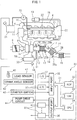
- FIG. 1 shows an overall view of a compression ignition type internal combustion engine.
- 1 indicates an engine body, 2 a combustion chamber of a cylinder, 3 an electronically controlled fuel injector for injecting fuel into each combustion chamber 2, 4 an intake manifold, and 5 an exhaust manifold.
- the intake manifold 4 is connected through an intake duct 6 to the outlet of a compressor 7a of an exhaust turbocharger 7.
- the inlet of the compressor 7a is connected through an intake air amount detector 8 to an air cleaner 9.
- a throttle valve 10 driven by an actuator is arranged inside of the intake duct 6, a throttle valve 10 driven by an actuator is arranged.
- a cooling device 11 is arranged for cooling the intake air flowing through the inside of the intake duct 6.
- the engine cooling water is guided to the inside of the cooling device 11 where the cooling water is used to cool the intake air.
- the exhaust manifold 5 is connected to the inlet of an exhaust turbine 7b of the exhaust turbocharger 7.
- the outlet of the exhaust turbine 7b is connected through an exhaust pipe 12 to the inlet of an exhaust treatment catalyst 13.
- this exhaust treatment catalyst 13 is comprised of a NO X storage catalyst.
- the outlet of the exhaust treatment catalyst 13 is connected to a particulate filter 14 carrying a NO X selective reduction catalyst thereon, and a sweeper catalyst 15 comprised of, for example, an oxidation catalyst is arranged downstream of the particulate filter 14.
- a fuel feed valve 16 for feeding, for example, a diesel fuel is arranged in the exhaust pipe 12 upstream of the exhaust treatment catalyst 13, and a urea feed valve 17 for feeding a urea water is arranged between the exhaust treatment catalyst 13 and the particulate filter 14.
- the exhaust manifold 5 and the intake manifold 4 are connected with each other through an exhaust gas recirculation (hereinafter referred to as an "EGR") passage 18.
- EGR exhaust gas recirculation
- an electronic control type EGR control valve 19 is arranged inside the EGR passage 18.
- a cooling device 20 is arranged for cooling the EGR gas flowing through the inside of the EGR passage 18.
- the engine cooling water is guided to the inside of the cooling device 20 where the cooling water is used to cool the EGR gas.
- Each fuel injector 3 is connected through a fuel feed pipe 21 to a common rail 22, and the common rail 22 is connected to a fuel tank 24 via an electronically controlled fuel pump 23 able to control the discharge rate.
- the fuel stored in the fuel tank 24 is supplied by the fuel pump 23 to the inside of the common rail 22.
- the fuel fed into the common rail 22 is fed through the fuel feed pipes 21 to the fuel injectors 3.
- the electronic control unit 30 is comprised of a digital computer provided with a ROM (read only memory) 32, RAM (random access memory) 33, CPU (microprocessor) 34, input port 35, and output port 36, which are interconnected with each other by a bidirectional bus 31.
- ROM read only memory
- RAM random access memory
- CPU microprocessor
- a differential pressure sensor 27 for detecting the differential pressure before and after the particulate filter 14 is attached to the particulate filter 14, and an air-fuel ratio sensor 28 is arranged downstream of the particulate filter 14.
- the output signals of these temperature sensors 25a, 25b, 25c, NO X sensors 26a, 26b, differential pressure sensor 27, air-fuel ratio sensor 28 and intake air amount detector 8 are input through corresponding AD converters 37 to the input port 35.
- an accelerator pedal 40 is connected to a load sensor 41 generating an output voltage proportional to the amount of depression of the accelerator pedal 40.
- the output voltage of the load sensor 41 is input through a corresponding AD converter 37 to the input port 35.
- the input port 35 is connected to a crank angle sensor 42 generating an output pulse each time a crankshaft rotates by for example 15°.
- the output port 36 is connected through corresponding drive circuits 38 to the fuel injectors 3, actuator for driving the throttle valve 10, fuel feed valve 16, urea feed valve 17, EGR control valve 19, and fuel pump 23.
- a heat and hydrogen generation device 50 which is able to generate heat and hydrogen or only heat is provided, and this heat and hydrogen generation device 50 is connected to the exhaust pipe 12 upstream of the exhaust treatment catalyst 13 via a feed conduit 51.
- This heat and hydrogen generation device 50 is started to operate, for example, at the time of the start of operation of the engine, and heat and hydrogen or only heat which are generated in the heat and hydrogen generation device 50 are fed to the exhaust treatment catalyst 13 via the feed conduit 51. Thereby, a warm up operation of the exhaust treatment catalyst 13 is performed by these heat and hydrogen or only heat.
- This heat and hydrogen generation device 50 is arranged, for example, inside the engine compartment of the vehicle.
- FIG. 2 shows an overall view of the heat and hydrogen generation device 50.
- This heat and hydrogen generation device 50 is cylindrically shaped as a whole.
- 52 indicates a cylindrical housing of the heat and hydrogen generation device 50, 53 a burner combustion chamber formed in the housing 52, 54 a reformer catalyst arranged in the housing 52, and 55 a gas outflow chamber formed in the housing 52.
- the reformer catalyst 54 is arranged at the center of the housing 52 in the longitudinal direction
- the burner combustion chamber 53 is arranged at one end part of the housing 52 in the longitudinal direction
- the gas outflow chamber 55 is arranged at the other end part of the housing 52 in the longitudinal direction.
- the entire outer circumference of the housing 52 is covered by a heat insulating material 56.
- a burner 57 provided with a fuel injector 58 is arranged at one end part of the burner combustion chamber 53.
- the tip of the fuel injector 58 is arranged in the burner combustion chamber 53, and a fuel injection port 59 is formed at the tip of the fuel injector 58.
- an air chamber 60 is formed around the fuel injector 58, and an air feed port 61 for ejecting air in the air chamber 60 toward the inside of the burner combustion chamber 53 is formed around the tip of the fuel injector 58.
- the fuel injector 58 is connected to the fuel tank 24 as shown in FIG. 1 , and fuel inside the fuel tank 24 is injected from the fuel injection port 59 of the fuel injector 58.
- this fuel is comprised of diesel fuel.
- the air chamber 60 is connected on one hand through a high temperature air flow passage 62 to an air pump 64 able to control the discharge rate and is connected on the other hand through a low temperature air flow passage 63 to the air pump 64 able to control the discharge rate.
- a high temperature air valve 65 and low temperature air valve 66 are arranged in the high temperature air flow passage 62 and the low temperature air flow passage 63, respectively.
- the high temperature air flow passage 62 is provided with a heat exchange part arranged in the gas outflow chamber 55. This heat exchange part is shown diagrammatically in FIG. 1 by reference notation 62a.
- this heat exchange part 62a may also be formed downstream of the reformer catalyst 54 around the housing 52 defining the gas outflow chamber 55. That is, it is preferable that this heat exchange part 62a is arranged or formed at a location where a heat exchange action is performed using the heat of the high temperature gas flowing out from the gas outflow chamber 55.
- the low temperature air flow passage 63 does not have a heat exchange part performing the heat exchange action using the heat of the high temperature gas flowing out from the gas outflow chamber 55 in this way.
- the high temperature air valve 65 opens and the low temperature air valve 66 is made to close, the outside air is fed through the air cleaner 67, air pump 64, high temperature air flow passage 62, and air chamber 60 into the burner combustion chamber 53 from the air feed port 61. At this time, the outside air, that is, air, is made to flow within the heat exchange part 62a.
- the low temperature air valve 66 opens and the high temperature air valve 65 is made to close, the outside air, that is, the air, is fed through the air cleaner 67, air pump 64, low temperature air flow passage 63, and air chamber 60 from the air feed port 61. Therefore, the high temperature air valve 65 and low temperature air valve 66 form a switching device able to switch the air flow passage for feeding air through the air chamber 60 to the air feed port 61 between the high temperature air flow passage 62 and the low temperature air flow passage 63.
- an ignition device 68 is arranged in the burner combustion chamber 53.
- this ignition device 68 is comprised of a glow plug.
- This glow plug 68 is connected through a switch 69 to a power supply 70.
- the reformer catalyst 54 is comprised of an oxidizing part 54a and a reforming part 54b.
- the substrate of the reformer catalyst 54 is comprised of zeolite. On this substrate, at the oxidizing part 54a, mainly palladium Pd is carried, while at the reforming part 54b, mainly rhodium Rh is carried.
- a temperature sensor 71 for detecting the temperature of the upstream side end face of the oxidizing part 54a of the reformer catalyst 54 is arranged in the burner combustion chamber 53, and a temperature sensor 72 for detecting the temperature of the downstream side end face of the reforming part 54b of the reformer catalyst 54 is arranged in the gas outflow chamber 55. Furthermore, a temperature sensor 73 for detecting the temperature of the air flowing within the low temperature air flow passage 63 is arranged in the low temperature air flow passage 63 positioned at the outside of the heat insulating material 56.
- the output signals of these temperature sensors 71, 72 and 73 are input to the input port 35 through corresponding AD converters 37 shown in FIG. 1 , respectively. Further, the output signal showing the resistance value of the glow plug 68 is input to the input port 35 through a corresponding AD converter 37 shown in FIG. 1 .
- the output port 36 shown in FIG. 1 is connected through corresponding drive circuits 38 to the fuel injectors 58, high temperature air valve 65, low temperature air valve 66, and switch 69. Furthermore, as shown in FIG. 1 , the output port 36 is connected to a pump drive circuit 44 controlling the discharge rate of the air pump 64. The discharge rate of the air pump 64 is controlled by this pump drive circuit 44 so as to become the instructed value of the discharge rate which is output to the output port 36.
- the heat and hydrogen generation device 50 is provided with the burner combustion chamber 53, the burner 57 arranged in the burner combustion chamber 53 for performing burner combustion, a fuel feed device able to control the amount of feed of the fuel fed from the burner 57 into the burner combustion chamber 53, an air feed device able to control the temperature and amount of feed of air fed from the burner 57 into the burner combustion chamber 53, the ignition device 68 for making the fuel ignite, and the reformer catalyst 54 to which the burner combustion gas is fed, and the air feed device is provided with the heat exchange part 62a for heating the air fed from the burner 57 into the burner combustion chamber 53 by the burner combustion gas.
- the fuel injector 58 forms the above-mentioned fuel feed device.
- the air chamber 60, air feed port 61, high temperature air flow passage 62, heat exchange part 62a, low temperature air flow passage 63, air pump 64, high temperature air valve 65, and low temperature air valve 66 form the above-mentioned air feed device.
- hydrogen is generated by reforming fuel in the heat and hydrogen generation device 50. Therefore, first, referring to FIG. 3 , reforming reactions in the case of using diesel fuel as fuel will be explained.
- (a) to (c) in FIG. 3 show a reaction formula when a complete oxidation reaction is performed, a reaction formula when a partial oxidation reforming reaction is performed, and a reaction formula when a steam reforming reaction is performed, respectively, with reference to the case of using the generally used diesel fuel as fuel.
- the heating value ⁇ H 0 in the reaction formulas are shown by the lower heating value (LHV).
- the steam reforming reaction is the method of adding steam to diesel fuel, and as will be understood from (C) in FIG.
- this steam reforming reaction is an endothermic reaction. Therefore, to cause the steam reforming reaction, it is necessary to add heat from the outside.
- the steam reforming reaction in which the generated heat is not discarded, but using the generated heat for generating hydrogen is used.
- the steam reforming reaction using the generated heat for generating hydrogen is not used.
- only the partial oxidation reforming reaction is used to generate hydrogen.
- This partial oxidation reforming reaction as will be understood from (b) in FIG. 3 , is an exothermic reaction. Therefore, the reforming reaction proceeds by the heat generated on its own even without adding heat from the outside, and hydrogen is generated.
- the reaction formula of the partial oxidation reforming reaction of (b) in FIG. 3 the partial oxidation reforming reaction is performed by a rich air-fuel ratio in which an O 2 /C molar ratio, showing the ratio of the air and fuel which are made to react, is 0.5. At this time, CO and H 2 are generated.
- FIG. 4 shows the relationship between a reaction equilibrium temperature TB when the air and fuel are reacted at the reformer catalyst and reach equilibrium and the O 2 /C molar ratio of the air and fuel.
- the solid line in FIG. 4 shows the theoretical value when the air temperature is 25°C.
- the equilibrium reaction temperature TB becomes substantially 830°C.
- the actual equilibrium reaction temperature TB at this time becomes somewhat lower than 830°C, but below, the equilibrium reaction temperature TB will be explained for an embodiment according to the present invention as the value shown by the solid line in FIG. 4 .
- the larger the O 2 /C molar ratio the greater the ratio by which the complete oxidation reaction is performed compared with the ratio by which the partial oxidation reforming reaction is performed, so the larger the O 2 /C molar ratio, the higher the reaction equilibrium temperature TB.
- FIG. 5 shows the relationship between the number of molecules (H 2 and CO) produced per atom of carbon and the O 2 /C molar ratio.
- the more the O 2 /C molar ratio exceeds 0.5 the less the ratio by which the partial oxidation reforming reaction is performed. Therefore, as shown in FIG. 5 , the more the O 2 /C molar ratio exceeds 0.5, the smaller the amounts of generation of H 2 and CO. Note that, while not described in FIG. 5 , if the O 2 /C molar ratio becomes larger than 0.5, due to the complete oxidation reaction shown in (a) of FIG. 3 , the amounts of generation of CO 2 and H 2 O increase. In this regard, FIG.
- the amount of generation of hydrogen becomes largest when the O 2 /C molar ratio is 0.5. Therefore, in the embodiment of the present invention, when the partial oxidation reforming reaction is performed for generating hydrogen, to avoid the occurrence of the coking and enable hydrogen to be generated most efficiently, the O 2 /C molar ratio is in principle made 0.5.
- FIG. 6 shows the temperature distribution inside the oxidizing part 54a and reforming part 54b of the reformer catalyst 54 when the reaction at the reformer catalyst 54 becomes an equilibrium state. Note that, this FIG. 6 shows the temperature distribution in the case where the outside air temperature is 25°C and this outside air is fed through the low temperature air flow passage 63 shown in FIG. 2 from the burner 57 to the inside of the burner combustion chamber 53.
- the solid line of FIG. 6 shows the temperature distribution inside the reformer catalyst 54 when the O 2 /C molar ratio of the air and fuel fed from the burner 57 is 0.5.
- the temperature of the reformer catalyst 54 rises toward the downstream side due to the heat of oxidation reaction due to the remaining oxygen.
- the combustion gas proceeds from inside the oxidizing part 54a of the reformer catalyst 54 to the inside of the reforming part 54b, the remaining oxygen in the combustion gas is consumed and a fuel reforming action is performed at the reforming part 54b of the reformer catalyst 54.
- This reforming reaction is an endothermic reaction.
- the temperature inside the reformer catalyst 54 falls as the reforming action proceeds, that is, toward the downstream side of the reformer catalyst 54.
- FIG. 6 shows by a broken line the temperature distribution inside the reformer catalyst 54 when the O 2 /C molar ratio of the air and fuel fed from the burner 57 is a lean air-fuel ratio of 2.6.
- the temperature inside the reformer catalyst 54 rises toward the downstream side reformer catalyst 54 due to the heat of oxidation reaction of the fuel inside the oxidizing part 54a of the reformer catalyst 54.
- no reforming action is performed inside the reforming part 54b of the reformer catalyst 54, so the temperature of the reformer catalyst 54 is maintained constant in the reforming part 54b.
- FIG. 7 shows the relationship between the reaction equilibrium temperature TB when the air and fuel are made to react at the reformer catalyst and reach equilibrium and the O 2 /C molar ratio of the air and fuel.
- TA shows the air temperature.
- FIG. 7 the relationship between the reaction equilibrium temperature TB and the O 2 /C molar ratio shown by the solid line in FIG. 4 is shown again by a solid line.
- reaction equilibrium temperature TB further shows the relationships between the reaction equilibrium temperature TB and the O 2 /C molar ratio when changing the air temperature TA to 225°C, 425°C, and 625°C by broken lines. From FIG. 7 , it will be understood that the reaction equilibrium temperature TB becomes higher overall regardless of the O 2 /C molar ratio if the air temperature TA rises.
- the reformer catalyst 54 used in the embodiment of the present invention does not greatly deteriorate due to heat if the catalyst temperature is 950°C or less. Therefore, in the embodiment of the present invention, 950°C is made the allowable catalyst temperature TX enabling heat degradation of the reformer catalyst 54 to be avoided.
- This allowable catalyst temperature TX is shown in FIG. 4 , FIG. 6, and FIG. 7 . As will be understood from FIG.
- the O 2 /C molar ratio can be made larger than 0.5, but the range by which the O 2 /C molar ratio can be enlarged is limited.
- the air temperature TA is made a low temperature of about 25°C, and the O 2 /C molar ratio is made 0.5 in a state maintaining the air temperature TA at about 25°C.
- burner combustion is started under a lean air-fuel ratio.
- This burner combustion under a lean air-fuel ratio is performed until the reforming action by the reformer catalyst 54 becomes possible.
- a warm-up operation of the heat and hydrogen generation device 50 is performed under a lean air-fuel ratio after startup of the heat and hydrogen generation device 50 until a reforming action by the reformer catalyst 54 becomes possible.
- the temperature of the reformer catalyst 54 becomes 700°C or so, a reforming action by the reformer catalyst 54 becomes possible.
- a warm-up operation of the heat and hydrogen generation device 50 is performed under a lean air-fuel ratio after startup of the heat and hydrogen generation device 50 until the temperature of the reformer catalyst 54 becomes 700°C.
- the heat generated at the heat and hydrogen generation device 50 is made to flow out from the gas outflow port 74 of the gas outflow chamber 55, then, as shown in FIG. 1 , is fed through the feed conduit 51 into the exhaust pipe 12.
- a reforming action by the reformer catalyst becomes possible, that is, if the temperature of the reformer catalyst 54 becomes 700°C
- the air-fuel ratio is switched from a lean air-fuel ratio to a rich air-fuel ratio and the partial oxidation reforming reaction is performed.
- the partial oxidation reforming reaction is performed, heat and hydrogen are generated at the reformer catalyst 54.
- this exhaust treatment catalyst 13 is comprised of an NO X storage catalyst.
- This NO X storage catalyst 13 carries a precious metal such as platinum Pt, palladium Pd, and rhodium Rh, and an alkali metal such as potassium K, sodium Na, and cesium Cs or an alkali earth metal such as barium Ba and calcium Ca.
- This NO X storage catalyst 13 has an NO X storage and release function of storing NO X contained in the exhaust gas when the air-fuel ratio of the exhaust gas flowing into the NO X storage catalyst 13 is lean and releasing the stored NO X from the NO X storage catalyst 13 when the air-fuel ratio of the exhaust gas flowing into the NO X storage catalyst 13 is rich. Further, in this NO X storage catalyst 13, the HC discharged from the engine is oxidized by the precious metal carried on the NO X storage catalyst 13. Therefore, this NO X storage catalyst 13 also has an HC removal function.
- the NO X storage rate to this NO X storage catalyst 13, that is, the NO X removal rate by the NO X storage catalyst 13 and the HC removal rate by the NO X storage catalyst 13, do not become sufficiently high unless the temperature of the NO X storage catalyst 13, that is, the exhaust treatment catalyst 13, becomes 200°C or so. Therefore, at the time of engine startup, to obtain a high NO X removal rate and high HC removal rate by the NO X storage catalyst 13, the temperature of the NO X storage catalyst 13, that is, the exhaust treatment catalyst 13, has to be made to rise until a target warm-up temperature of about 200°C.
- a warm-up action of the exhaust treatment catalyst 13 is started by the exhaust gas discharged from the engine.
- a long time is required for making the temperature of the exhaust treatment catalyst 13 rise to the target warm-up temperature by exhaust gas. Therefore, in the embodiment of the present invention, to make the temperature of the exhaust treatment catalyst 13 quickly rise to the target warm-up temperature, at the same time as startup of the engine, operation of the heat and hydrogen generation device 50 is started, and the warm-up action of the exhaust treatment catalyst 13 is prompted by the heat and hydrogen fed from the heat and hydrogen generation device 50 to the exhaust treatment catalyst 13 or the heat fed from the heat and hydrogen generation device 50 to the exhaust treatment catalyst 13.
- FIG. 8A and FIG. 8B a warm-up promotion action of the exhaust treatment catalyst 13 by the heat and hydrogen generation device 50 will be explained.
- FIG. 8A and FIG. 8B show the change of the temperature TD of the exhaust treatment catalyst 13 when the warm up operation of the exhaust treatment catalyst 13 is performed by using the heat and hydrogen generation device 50 in the case where the exhaust treatment catalyst 13 carries a precious metal such as platinum Pt, palladium Pd, and rhodium Rh.
- the abscissa shows the elapse of time.
- TK shows the temperature at which the precious metal becomes activated.
- this temperature TK at which the precious metal becomes activated is made 110°C. Note that, below, this temperature TK at which the precious metal becomes activated will be called the "activation temperature TK of the exhaust treatment catalyst 13".
- the complete oxidation reaction is far greater in amount of heat generated compared with the partial oxidation reforming reaction. Therefore, if the amount of fuel used is the same, the amount of heat fed to the exhaust treatment catalyst 13 is far larger when the complete oxidation reaction is performed in the heat and hydrogen generation device 50 compared to when the partial oxidation reforming reaction is performed in the heat and hydrogen generation device 50.
- the complete oxidation reaction is far greater in amount of heat generated compared with the partial oxidation reforming reaction. Therefore, if the amount of fuel used is the same, the amount of heat fed to the exhaust treatment catalyst 13 is far larger when the complete oxidation reaction is performed in the heat and hydrogen generation device 50 compared to when the partial oxidation reforming reaction is performed in the heat and hydrogen generation device 50.
- the rate of rise of the temperature TD of the exhaust treatment catalyst 13 when the exhaust treatment catalyst 13 is warmed up by only the heat generated at the heat and hydrogen generation device 50 is faster in the case of the complete oxidation reaction than the partial oxidation reforming reaction.
- the rate of rise of the temperature TD of the exhaust treatment catalyst 13 is far faster in the partial oxidation reforming reaction than the complete oxidation reaction.
- part of the heat of the combustion gas generated at the heat and hydrogen generation device 50 escapes to the outside while the combustion gas flows through the inside of the feed conduit 51. Further, this heat of combustion gas is just fed by heat transfer to the exhaust treatment catalyst 13, so in actuality the amount of heat used for heating the exhaust treatment catalyst 13 is not that great.
- the hydrogen generated at the heat and hydrogen generation device 50 is not consumed until reaching the exhaust treatment catalyst 13, and the exhaust treatment catalyst 13 itself is directly heated by the heat of the oxidation reaction of hydrogen. Therefore, the exhaust treatment catalyst 13 is made to rapidly rise in temperature by the heat of the oxidation reaction of the hydrogen.
- the complete oxidation reaction is made to continue at the heat and hydrogen generation device 50 until the temperature TD of the exhaust treatment catalyst 13 becomes higher than the activation temperature TK, and when the temperature TD of the exhaust treatment catalyst 13 becomes higher than the activation temperature TK, the reaction at the heat and hydrogen generation device 50 is switched from the complete oxidation reaction to the partial oxidation reforming reaction. By doing this, it is possible to speed up the warm-up of the exhaust treatment catalyst 13 the fastest.
- the exhaust purification system of an internal combustion engine comprises the exhaust treatment catalyst 13 arranged in the engine exhaust passage and the heat and hydrogen generation device 50 able to feed only heat or heat and hydrogen to the exhaust treatment catalyst 13 so as to warm up the exhaust treatment catalyst 13.
- the heat and hydrogen generation device 50 is provided with the reformer catalyst 54 to which combustion gas of the fuel and air is fed.
- the warm-up operation of the heat and hydrogen generation device 50 is performed under a lean air-fuel ratio until the reforming action by the reformer catalyst 54 becomes possible. If the reforming action by the reformer catalyst 54 becomes possible, the partial oxidation reaction is performed and heat and hydrogen are generated.
- the reforming action by the reformer catalyst 54 becomes possible after the warm-up operation of the heat and hydrogen generation device 50 is completed, if the temperature TD of the exhaust treatment catalyst 13 is the preset activation temperature TK or more, the partial oxidation reaction is performed at the heat and hydrogen generation device 50 and the generated heat and hydrogen are fed to the exhaust treatment catalyst 13.
- the temperature TD of the exhaust treatment catalyst 13 is less than the preset activation temperature TK, the complete oxidation reaction by the lean air-fuel ratio is continued and only heat is fed to the exhaust treatment catalyst 13.
- the complete oxidation reaction by a lean air-fuel ratio is continued, then, if the temperature TD of the exhaust treatment catalyst 13 becomes the preset activation temperature TK or more, the complete oxidation reaction by a lean air-fuel ratio is switched to the partial oxidation reforming reaction.
- the relationship shown in FIG. 8A and FIG. 8B is not limited to the case of using an NO X storage catalyst as the exhaust treatment catalyst 13.
- the relationship shown in FIG. 8A and FIG. 8B similarly arises even when using a catalyst carrying a precious metal such as platinum Pt, palladium Pd, and rhodium Rh as the exhaust treatment catalyst 13, for example, an oxidation catalyst. Therefore, the present invention can be applied even if using an oxidation catalyst as the exhaust treatment catalyst 13.
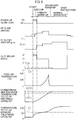
- FIG. 9 shows the case where the temperature TD of the exhaust treatment catalyst 13 is the preset activation temperature TK or more when the warm-up operation of the heat and hydrogen generation device 50 is completed and the reforming action by the reformer catalyst 54 becomes possible. Further, in this FIG. 9 , the temperature TD of the exhaust treatment catalyst 13 is the preset activation temperature TK or more when the warm-up operation of the heat and hydrogen generation device 50 is completed and the reforming action by the reformer catalyst 54 becomes possible. Further, in this FIG.
- the operating state of the glow plug 68, the amount of feed of air from the burner 57, the amount of feed of fuel from the burner 57, the O 2 /C molar ratio of the air and fuel which are reacted, the temperature of the air fed from the burner 57, the temperature TC of the downstream side end face of the reformer catalyst 54, and the temperature TD of the exhaust treatment catalyst 13 are shown.
- the target temperatures for the temperature TC of the downstream side end face of the reformer catalyst 54 shown in FIG. 9 etc. and the target temperatures for the temperature of the reformer catalyst 54 are theoretical values, and in the embodiment of the present invention, as explained above, for example, the actual equilibrium reaction temperature TB becomes somewhat lower than the target temperature of 830°C.
- These target temperatures change depending on the structure of the heat and hydrogen generation device 50 etc. Therefore, in actuality, it is necessary to perform experiments to set in advance the optimum target temperatures corresponding to the structure of the heat and hydrogen generation device 50.
- the heat and hydrogen generation device 50 is simultaneously started. If the heat and hydrogen generation device 50 is started, the glow plug 68 is turned on. Next, air is fed through the high temperature air flow passage 62 to the burner combustion chamber 53. In this case, in FIG. 9 , as shown by the broken line, the air can be fed through the high temperature air flow passage 62 to the burner combustion chamber 53, then the glow plug 68 turned on. Next, fuel is injected from the burner 57. If the fuel injected from the burner 57 is ignited by the glow plug 68, the amount of fuel is increased, the O 2 /C molar ratio of the air and fuel which are reacted is decreased from 4.0 to 3.0, and burner combustion is started in the burner combustion chamber 53. In the time period from when the feed of fuel is started to when the fuel is ignited, the air-fuel ratio is made a lean air-fuel ratio so as to keep down the amount of generation of HC as much as possible.
- burner combustion that is, the complete oxidation reaction by a lean air-fuel ratio is continued. Due to this, the temperature of the reformer catalyst 54 is gradually made to rise.
- the temperature of the gas flowing out through the reformer catalyst 54 to the gas outflow chamber 55 gradually rises. Therefore, the temperature of the air heated at the heat exchanger 62a due to this gas also gradually rises and as a result the temperature of the air fed from the high temperature air flow passage 62 to the burner combustion chamber 53 gradually rises. Due to this, the warm-up of the reformer catalyst 54 is promoted.
- the warm-up of the reformer catalyst 54 performed under a lean air-fuel ratio in this way will be referred to as "primary warm-up” as shown in FIG. 9 , or "warm-up of the heat and hydrogen generation device 50". Note that, in the example shown in FIG. 9 , the amount of feed of air and the amount of fuel are increased during this primary warm-up operation.
- This primary warm-up operation that is, the warm-up operation of the heat and hydrogen generation device 50, is continued until the fuel can be reformed at the reformer catalyst 54.
- the primary warm-up operation that is, the warm-up operation of the heat and hydrogen generation device 50, is continued until the temperature TC of the downstream side end face of the reformer catalyst 54 becomes 700°C. Note that, in the example shown in FIG. 9 , as shown in FIG.
- the O 2 /C molar ratio of the air and fuel which are made to react is made 3.0 to 4.0 and the complete oxidation reaction by a lean air-fuel ratio is performed from when operation of the hydrogen generation device 50 is started to when primary warm-up of the reformer catalyst 54 is completed, that is, from when the operation of the hydrogen generation device 50 is started to when warm-up of the heat and hydrogen generation device 50 is completed.
- the temperature of the reformer catalyst 54 is considerably lower than the allowable catalyst temperature TX, so the O 2 /C molar ratio of the air and fuel which are made to react may also, for example, be made an O 2 /C molar ratio close to the stoichiometric air-fuel ratio such as 2.0 to 3.0.
- the temperature TD of the exhaust treatment catalyst 13 immediately rises a bit as shown in FIG. 9 .
- the temperature TD of the exhaust treatment catalyst 13 rises a bit at a time, and the temperature TD of the exhaust treatment catalyst 13 exceeds the preset activation temperature TK while the primary warm-up operation, that is, the warm-up operation of the heat and hydrogen generation device 50, is being performed.
- the temperature TD of the exhaust treatment catalyst 13 exceeds the preset activation temperature TK in this way, in the heat and hydrogen generation device 50, the complete oxidation reaction by a lean air-fuel ratio is continued.
- the temperature TD of the exhaust treatment catalyst 13 further rises a bit at a time.
- the temperature TD of the exhaust treatment catalyst 13 becomes the preset activation temperature TK or more.
- the temperature TD of the exhaust treatment catalyst 13 becomes the preset activation temperature TK or more, and therefore the partial oxidation reforming reaction for generating hydrogen is started.
- the secondary warm-up operation is performed, and if the secondary warm-up operation is completed, the normal operation is performed. This secondary warm-up operation is performed for generating hydrogen while further making the temperature of the reformer catalyst 54 rise. If the secondary warm-up operation is started, the heat and hydrogen generated at the heat and hydrogen generation device 50 are fed to the exhaust treatment catalyst 13. As a result, as shown in FIG. 9 , the temperature TD of the exhaust treatment catalyst 13 rapidly rises.
- this secondary warm-up operation is continued until the temperature TC of the downstream side end face of the reformer catalyst 54 reaches the reaction equilibrium temperature TB and shifts to the normal operation when the temperature TC of the downstream side end face of the reformer catalyst 54 reaches the reaction equilibrium temperature TB.
- the demanded value of the output heat amount (kW) of the heat and hydrogen generation device 50 required for making the temperature TD of the exhaust treatment catalyst 13 rise to the target warm-up temperature is calculated.
- the demanded value of this output heat amount (kW) basically is calculated based on the product of the temperature difference between the target warm-up temperature of the exhaust treatment catalyst 13 and the current exhaust gas temperature and the amount of exhaust gas discharged from the engine.
- the target fuel feed amount required for generating this demanded output heat amount (kW) is calculated.
- the amount of feed of fuel from the burner 57 is made this target fuel feed amount.
- the exhaust treatment catalyst 13 is comprised of an NO X storage catalyst
- the above-mentioned target warm-up temperature of the exhaust treatment catalyst 13, as explained above, is made for example 200°C. Therefore, in the example shown in FIG. 9 , the output heat amount (kW) of the heat and hydrogen generation device 50 required for making the temperature TD of the exhaust treatment catalyst 13 rise to 200°C is made the demanded value.
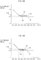
- the operating region GG of the heat and hydrogen generation device 1 where this secondary warm-up operation is performed is shown by the hatched region surrounded by the solid lines GL, GU, and GS. Note that in FIG. 10A , the ordinate shows the O 2 /C molar ratio of air and fuel which are made to react, while the abscissa shows the temperature TC of the downstream side end face of the reformer catalyst 54.
- the solid line GL in FIG. 10A shows the boundary of the O 2 /C molar ratio with respect to the occurrence of coking. In the region where the O 2 /C molar ratio is smaller than this boundary GL, coking occurs. Note that, if the temperature of the reformer catalyst 54 becomes lower, even if the O 2 /C molar ratio becomes larger, that is, even if the degree of richness of the air-fuel ratio falls, the carbon C will deposit in the pores of the substrate of the reformer catalyst without being oxidized and coking will occur. Therefore, as shown in FIG.
- the boundary GL of the O 2 /C molar ratio causing coking becomes higher the lower the temperature of the reformer catalyst 54. Therefore, to avoid the occurrence of coking, the partial oxidation reforming reaction, that is, the secondary warm-up operation and the normal operation of the heat and hydrogen generation device 50, is performed on the boundary GL of this O 2 /C molar ratio or above the boundary GL.
- the solid line GU shows the upper limit guard value of the O 2 /C molar ratio for preventing the temperature of the reformer catalyst 54 from exceeding the allowable catalyst temperature TX at the time of the secondary warm-up operation of the heat and hydrogen generation device 50
- the solid line GS shows the upper limit guard value of the temperature TC of the downstream side end face of the reformer catalyst 54 for preventing the temperature of the reformer catalyst 54 from exceeding the allowable catalyst temperature TX at the time of the secondary warm-up operation of the heat and hydrogen generation device 50.
- FIG. 10B shows one example of the secondary warm-up operation control until shifting to normal operation.
- the reforming reaction at the reformer catalyst 54 becomes the equilibrium state.
- the O 2 /C molar ratio is maintained at 0.5 and the operation of the heat and hydrogen generation device 50 is shifted to the normal operation.
- the temperature TC of the downstream side end face of the reformer catalyst 54 is maintained at 830°C, and therefore, the temperature of the reformer catalyst 54 is maintained at the allowable catalyst temperature TX or less. Therefore, it is possible to avoid heat degradation of the reformer catalyst 54 while generating hydrogen by the partial oxidation reforming reaction.
- the feed of high temperature air from the high temperature air flow passage 62 to the burner combustion chamber 53 is stopped and low temperature air is fed from the low temperature air flow passage 63 to the burner combustion chamber 53. That is, as shown in FIG. 9 , the temperature of the feed air is lowered. After that, low temperature air continues to be fed from the low temperature air flow passage 63 to the burner combustion chamber 53 until the normal operation is ended.
- the temperature TA of the air which is made to react with the fuel explained above means the temperature of the air used when calculating the equilibrium reaction temperature TB such as shown in FIG. 4 and is the temperature of air not affected by the heat of reaction of the burner combustion in the burner combustion chamber 53.
- the air fed from the air feed port 61 or the air inside the air chamber 60 is affected by the heat of reaction of the burner combustion.
- These airs absorb the energy of the heat of reaction of the burner combustion and rise in temperature. Therefore, the temperature of these airs shows the temperature of the air already in the reaction process. Therefore, it is not the temperature of the air when calculating the equilibrium reaction temperature TB.
- the temperature sensor 73 is arranged at the low temperature air flow passage 63 positioned at the outside of the heat insulating material 56. The temperature detected by this temperature sensor 73 is used as the temperature TA of the air when calculating the equilibrium reaction temperature TB.
- the feed of high temperature air from the high temperature air flow passage 62 to the burner combustion chamber 53 is stopped and low temperature air is fed from the low temperature air flow passage 63 to the burner combustion chamber 53.
- the air flow route for feeding air to the burner combustion chamber 53 is switched from the high temperature air flow route for feeding high temperature air to the low temperature air flow route for feeding low temperature air.
- a switching device comprised of the high temperature air valve 65 and the low temperature air valve 66 is provided.
- the air flow route from the air cleaner 67 through the high temperature air flow passage 62 to the air feed port 61 corresponds to the high temperature air flow route
- the air flow route from the air cleaner 67 through the low temperature air flow passage 63 to the air feed port 61 corresponds to the low temperature air flow route.
- the temperature TD of the exhaust treatment catalyst 13 is less than the preset activation temperature TK.
- the operating state of the glow plug 68, the amount of feed of air from the burner 57, the amount of feed of fuel from the burner 57, the O 2 /C molar ratio of the air and fuel which are made to react, the temperature of the air fed from the burner 57, the temperature TC of the downstream side end face of the reformer catalyst 54, and the temperature TD of the exhaust treatment catalyst 13 are shown.
- the heat and hydrogen generation device 50 is simultaneously started up. If the engine is started up, the temperature TD of the exhaust treatment catalyst 13 immediately rises slightly. Next, while the primary warm-up operation, that is, the warm-up operation of the heat and hydrogen generation device 50, is being performed, that is, while the complete oxidation reaction by a lean air-fuel ratio is continuing in the heat and hydrogen generation device 50, the temperature TD of the exhaust treatment catalyst 13 rises a bit at a time.
- the primary warm-up operation that is, the warm-up operation of the heat and hydrogen generation device 50
- the operation mode when the complete oxidation reaction by a lean air-fuel ratio is performed from when the temperature TC of the downstream side end face of the reformer catalyst 54 reaches 700°C to when the temperature TD of the exhaust treatment catalyst 13 reaches the preset activation temperature TK will be called the "heat generation mode" as shown in FIG. 11 .
- the demanded value of the output heat amount (kW) of the heat and hydrogen generation device 50 required for making the temperature TD of the exhaust treatment catalyst 13 rise to the target warm-up temperature is calculated, then the target fuel feed amount required for generating the demanded output heat amount (kW) is calculated.
- the amount of feed of fuel from the burner 57 is increased to this target fuel feed amount as shown in FIG. 11 .
- the operation mode is made the heat generation mode, as will be understood from FIG. 11 , the reforming action at the reformer catalyst 54 is not in the equilibrium state, so even if the air temperature TA is high, the temperature of the reformer catalyst 54 does not rise as shown in FIG. 7 .
- the complete oxidation reaction by a lean air-fuel ratio is being performed in the state of a high temperature of the reformer catalyst 54, so there is the danger of the temperature of the reformer catalyst 54 ending up becoming higher than the allowable catalyst temperature TX for some reason or another.
- the feed of high temperature air from the high temperature air flow passage 62 to the burner combustion chamber 53 is stopped and low temperature air is fed from the low temperature air flow passage 63 to the burner combustion chamber 53. That is, as shown in FIG. 11 , the temperature of the air feed is made to decrease. After that, low temperature air continues to be fed from the low temperature air flow passage 63 to the burner combustion chamber 53.
- the operation mode is made the heat generation mode
- the temperature TD of the exhaust treatment catalyst 13 reaches the preset activation temperature TK
- the O 2 /C molar ratio is changed from 2.6 to 0.5 and the normal operation is started.
- the temperature TD of the exhaust treatment catalyst 13 is made to rapidly rise until the target warm-up temperature.
- a stop instruction is issued, as shown in FIG. 11
- the feed of fuel is stopped then, after a while, the feed of air is stopped.
- the activation temperature TK of the exhaust treatment catalyst 13, that is, the temperature TK at which the precious metal becomes activated, is made 110°C.
- the concentration of the olefins in the exhaust gas increases. These olefins are adsorbed at the surface of the precious metal carried on the exhaust treatment catalyst 13 to act to poison the precious metal. Therefore, if the concentration of olefins in the exhaust gas increases, poisoning of the precious metal carried on the exhaust treatment catalyst 13 progresses.
- the temperature TK at which the precious metal becomes activated that is, the activation temperature TK of the exhaust treatment catalyst 13 becomes higher. Therefore, in the embodiment of the present invention, when a premixed charge combustion is being performed in the engine, the activation temperature TK preset for the exhaust treatment catalyst 13 is made higher.
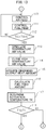
- This heat and hydrogen generation control routine is performed when the starter switch 43 of the engine shown in FIG. 1 is turned on or when during operation of the engine, the temperature of the reformer catalyst 4 falls, for example, below the target warm-up temperature.
- the starter switch 43 of the engine is sometimes manually turned on by the driver and sometimes automatically turned on like in a hybrid vehicle driven by an engine and electric motor.
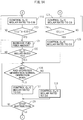
- the heat and hydrogen generation control routine is performed, first, at step 100 of FIG. 12 , based on the output signal of the temperature sensor 71, it is judged if the temperature TCU of the upstream side end face of the reformer catalyst 54 is a temperature at which an oxidation reaction can be performed on the upstream side end face of the reformer catalyst 54, for example, 300°C or more. If the temperature TCU of the upstream side end face of the reformer catalyst 54 is 300°C or less, the routine proceeds to step 101 where the glow plug 68 is turned on. Next, at step 102, it is judged if a fixed time has elapsed from when the glow plug 68 is turned on. When the fixed time has elapsed, the routine proceeds to step 103.
- the air pump 64 is made to operate and air is fed through the high temperature air flow passage 62 to the burner combustion chamber 53.
- the high temperature air valve 65 is opened and the low temperature air valve 66 is closed. Therefore, when the heat and hydrogen generation device 50 is made to operate, air is fed through the high temperature air flow passage 62 to the burner combustion chamber 53.
- the temperature TG of the glow plug 68 is calculated from the resistance value of the glow plug 68.
- step 106 fuel is injected from the burner 57 to the burner combustion chamber 53.
- step 107 the temperature TCU of the upstream side end face of the reformer catalyst 54 is detected based on the output signal of the temperature sensor 71.
- step 108 it is judged if the fuel has been ignited from the output signal of the temperature sensor 71. If the fuel is ignited, the temperature TCU of the upstream side end face of the reformer catalyst 54 instantaneously rises. Therefore, it becomes possible to judge if fuel has been ignited from the output signal of the temperature sensor 71.
- step 108 When at step 108 it is judged that the fuel has not been ignited, the routine returns to step 106, while when at step 108 it is judged that the fuel has been ignited, the routine proceeds to step 109 where the glow plug 68 is turned off. Next, the routine proceeds to step 110 of FIG. 13 . Note that if the fuel is ignited, the temperature TCU at the upstream side end face of the reformer catalyst 54 immediately becomes a temperature able to perform an oxidation reaction at the upstream side end face of the reformer catalyst 54, for example, 300°C or more. On the other hand, when at step 100 it is judged that the temperature TCU of the upstream side end face of the reformer catalyst 54 is 300°C or more, the routine proceeds to step 110.
- the primary warm-up operation is performed. That is, at step 110, the amount of discharge of the air pump 65 is controlled, while at step 111, the amount of feed of fuel from burner 57 is controlled so that the O 2 /C molar ratio becomes 3.0. Note that, in the embodiment of the present invention, when this primary warm-up operation is being performed, as shown in FIG. 9 and FIG. 11 , the amount of feed of air and the amount of feed of fuel are increased in stages.
- step 112 based on the output signal of the temperature sensor 72, it is judged if the temperature TC of the downstream side end face of the reformer catalyst 54 exceeds 700°C.
- the routine returns to step 110 where the primary warm-up operation, that is, the warm-up operation of the heat and hydrogen generation device 50, continues to be performed.
- the routine proceeds to step 113.
- the low temperature air valve 66 is opened and, at step 114, the high temperature air valve 65 is closed. Therefore, at this time, air is fed through the low temperature air flow passage 63 to the burner combustion chamber 53.
- the demanded value of the output heat amount (kW) of the heat and hydrogen generation device 50 required for making the temperature TD of the exhaust treatment catalyst 13 rise to the target warm-up temperature is calculated.
- the target fuel feed amount required for generating the demanded output heat amount (kW) is calculated.
- the activation temperature TK of the exhaust treatment catalyst 13, that is, the temperature TK at which the precious metal becomes activated, is determined in accordance with the mode of combustion currently being performed in the engine. That is, when normal combustion by diffusion combustion is currently being performed in the engine, the activation temperature TK is made 110°C. As opposed to this, when the premixed charge combustion is currently being performed in the engine, the activation temperature TK is made a temperature higher than 110°C.
- the activation temperature TK when the premixed combustion is being performed in the engine is found in advance by experiments in accordance with the mode of the premixed charge combustion, for example, is made 140°C.
- step 117 the routine proceeds to step 118 where it is judged if the temperature TD of the exhaust treatment catalyst 13 is higher than the activation temperature TK.
- the temperature TD of the exhaust treatment catalyst 13 is found from one or both detection signals of the temperature sensor 25a and the temperature sensor 25b shown in FIG. 1 .
- step 118 When at step 118 it is judged that the temperature TD of the exhaust treatment catalyst 13 is higher than the activation temperature TK, the routine proceeds to step 119 where, as shown in FIG. 9 , the secondary warm-up operation is started. That is, at step 119, the amount of discharge of the air pump 64 is made to decrease so that the O 2 /C molar ratio becomes 0.56 in the state where the amount of feed of fuel from the burner 57 is made the target fuel feed amount. At this time, the partial oxidation reforming reaction is started and heat and hydrogen are fed to the exhaust treatment catalyst 13.
- step 120 it is judged if the temperature TC of the downstream side end face of the reformer catalyst 54 reaches the sum (TA+805°C)of the air temperature TA detected by the temperature sensor 73 and 805°C.
- the routine returns to step 119 where the amount of discharge of the air pump 64 continues to be controlled so that the O 2 /C molar ratio becomes 0.56.
- the routine proceeds to step 121 where the amount of fuel injection is gradually increased to the amount of feed of fuel calculated at step 116 in the state where the amount of discharge of the air pump 15 is maintained constant. As a result, the O 2 /C molar ratio gradually decreases.
- step 122 it is judged if the O 2 /C molar ratio becomes 0.5.
- the routine returns to step 121.
- the routine proceeds to step 126 where the normal operation is performed.
- step 118 when at step 118 it is judged that the temperature TD of the exhaust treatment catalyst 13 is less than the activation temperature TK, the routine proceeds to step 123 where, as shown in FIG. 11 , the operation mode is made the heat generation mode. That is, at step 123, fuel is injected from the burner 57 by an amount of feed of fuel calculated at step 116, and the amount of discharge of the air pump 64 is controlled to give the O 2 /C molar ratio 2.6. At this time, the complete oxidation reaction under a lean air-fuel ratio is continued and only heat is fed to the exhaust treatment catalyst 13.
- step 124 it is judged if the temperature TD of the exhaust treatment catalyst 13 reaches the activation temperature TK. When the temperature TD of the exhaust treatment catalyst 13 does not reach the activation temperature TK, the routine returns to step 123.
- step 124 when at step 124 it is judged that the temperature TD of the exhaust treatment catalyst 13 reaches the activation temperature TK, the routine proceeds to step 125 where the amount of discharge of the air pump 64 is made to decrease so that the O 2 /C molar ratio becomes 0.5 in the state maintaining the amount of feed of fuel from the burner 57 as it is. At this time, the partial oxidation reforming reaction is started and heat and hydrogen are fed to the exhaust treatment catalyst 13. Next, the routine proceeds to step 126 where the normal operation is performed.
- step 126 it is judged if the mode is the heat and hydrogen generation normal operation mode.
- the routine proceeds to step 129.
- step 129 it is judged if the operation of the heat and hydrogen generation device 50 should be stopped.
- the routine returns to step 126.
- the routine proceeds to step 130 where fuel injection from the burner 57 is stopped.
- step 131 to burn off the remaining fuel, air continues to be fed from the air pump 64.
- step 132 it is judged if a fixed time has elapsed. When it is judged that the fixed time has not elapsed, the routine returns to step 131. As opposed to this, when at step 132 it is judged that the fixed time has elapsed, the routine proceeds to step 133 where operation of the air pump 65 is stopped and the feed of air to the burner combustion chamber 53 is stopped.
- step 134 the low temperature air valve 66 is closed while, at step 135, the high temperature air valve 65 is opened. Next, while the operation of the heat and hydrogen generation device 50 is being made to stop, the low temperature air valve 66 continues closed and the high temperature air valve 65 continues open.
- step 200 the temperature TC of the downstream side end face of the reformer catalyst 54 detected by the temperature sensor 72 is read.
- step 201 it is judged if the temperature TC of the downstream side end face of the reformer catalyst 54 exceeds the allowable catalyst temperature TX.
- the processing cycle is ended.
- step 201 when at step 201 it is judged that the temperature TC of the downstream side end face of the reformer catalyst 54 exceeds the allowable catalyst temperature TX, the routine proceeds to step 202 where the low temperature air valve 66 is opened. Next, at step 203, the high temperature air valve 65 is closed. Next, the processing cycle is ended. That is, during operation of the heat and hydrogen generation device 50, when the temperature TC of the downstream side end face of the reformer catalyst 54 exceeds the allowable catalyst temperature TX, the air flow route for feeding air to the burner combustion chamber 53 is switched from the high temperature air flow route for feeding high temperature air to the low temperature air flow route for feeding low temperature air, and thereby the temperature of the burner combustion-use air fed to the burner combustion chamber 53 is made to fall.
Landscapes
- Engineering & Computer Science (AREA)
- Chemical & Material Sciences (AREA)
- Chemical Kinetics & Catalysis (AREA)
- Combustion & Propulsion (AREA)
- Mechanical Engineering (AREA)
- General Engineering & Computer Science (AREA)
- Health & Medical Sciences (AREA)
- Toxicology (AREA)
- Materials Engineering (AREA)
- Hydrogen, Water And Hydrids (AREA)
- Exhaust Gas After Treatment (AREA)
- Exhaust Gas Treatment By Means Of Catalyst (AREA)
Applications Claiming Priority (1)
| Application Number | Priority Date | Filing Date | Title |
|---|---|---|---|
| JP2016206162A JP6528755B2 (ja) | 2016-10-20 | 2016-10-20 | 内燃機関の排気浄化装置 |
Publications (3)
| Publication Number | Publication Date |
|---|---|
| EP3333384A2 true EP3333384A2 (de) | 2018-06-13 |
| EP3333384A3 EP3333384A3 (de) | 2018-08-29 |
| EP3333384B1 EP3333384B1 (de) | 2019-09-11 |
Family
ID=60153138
Family Applications (1)
| Application Number | Title | Priority Date | Filing Date |
|---|---|---|---|
| EP17197336.5A Not-in-force EP3333384B1 (de) | 2016-10-20 | 2017-10-19 | Abgasreinigungssystem für einen verbrennungsmotor |
Country Status (4)
| Country | Link |
|---|---|
| US (1) | US10267192B2 (de) |
| EP (1) | EP3333384B1 (de) |
| JP (1) | JP6528755B2 (de) |
| CN (1) | CN107965374B (de) |
Families Citing this family (1)
| Publication number | Priority date | Publication date | Assignee | Title |
|---|---|---|---|---|
| KR20210071578A (ko) * | 2019-12-06 | 2021-06-16 | 현대자동차주식회사 | 차량용 촉매 컨버터 |
Citations (1)
| Publication number | Priority date | Publication date | Assignee | Title |
|---|---|---|---|---|
| JP2008298000A (ja) | 2007-06-01 | 2008-12-11 | Honda Motor Co Ltd | 燃料改質システム及び燃料改質方法 |
Family Cites Families (13)
| Publication number | Priority date | Publication date | Assignee | Title |
|---|---|---|---|---|
| JPH0610411B2 (ja) * | 1989-12-06 | 1994-02-09 | 株式会社新燃焼システム研究所 | 車両搭載用燃料改質装置 |
| DE19537800A1 (de) * | 1994-10-21 | 1996-04-25 | Volkswagen Ag | Abgasanlage mit Wärmetauscher |
| WO2002061244A1 (en) * | 2001-01-29 | 2002-08-08 | Mitsubishi Jidosha Kogyo Kabushiki Kaisha | Exhaust emission control device of internal combustion engine |
| US6895746B2 (en) * | 2002-05-31 | 2005-05-24 | Utc Fuel Cells, Llc | Reducing oxides of nitrogen using hydrogen generated from engine fuel and exhaust |
| WO2006099069A1 (en) * | 2005-03-10 | 2006-09-21 | Arvin Technologies, Inc. | Plasma fuel reformer |
| DE102006050560A1 (de) * | 2006-06-03 | 2007-12-06 | Bayerische Motoren Werke Ag | Betriebsverfahren für ein System aus einem Reformer und einer katalytischen Abgas-Nachbehandlungsvorrichtung |
| DE102007039081A1 (de) * | 2007-08-18 | 2009-02-19 | J. Eberspächer GmbH & Co. KG | Brennkraftmaschinensystem |
| US8074443B2 (en) | 2007-11-13 | 2011-12-13 | Eaton Corporation | Pre-combustor and large channel combustor system for operation of a fuel reformer at low exhaust temperatures |
| JP5081635B2 (ja) * | 2008-01-08 | 2012-11-28 | 本田技研工業株式会社 | 内燃機関の排気浄化装置 |
| JP2010270664A (ja) | 2009-05-21 | 2010-12-02 | Honda Motor Co Ltd | 内燃機関の排気浄化システム |
| JP2010281266A (ja) * | 2009-06-04 | 2010-12-16 | Honda Motor Co Ltd | 内燃機関の排気浄化装置 |
| EP2863026A4 (de) * | 2012-04-27 | 2016-03-02 | Hino Motors Ltd | Brenner und filtererneuerungsvorrichtung |
| JP6156108B2 (ja) * | 2013-12-05 | 2017-07-05 | 株式会社デンソー | 高活性物質添加装置 |
-
2016
- 2016-10-20 JP JP2016206162A patent/JP6528755B2/ja not_active Expired - Fee Related
-
2017
- 2017-08-21 US US15/681,821 patent/US10267192B2/en not_active Expired - Fee Related
- 2017-09-21 CN CN201710860011.0A patent/CN107965374B/zh not_active Expired - Fee Related
- 2017-10-19 EP EP17197336.5A patent/EP3333384B1/de not_active Not-in-force
Patent Citations (1)
| Publication number | Priority date | Publication date | Assignee | Title |
|---|---|---|---|---|
| JP2008298000A (ja) | 2007-06-01 | 2008-12-11 | Honda Motor Co Ltd | 燃料改質システム及び燃料改質方法 |
Also Published As
| Publication number | Publication date |
|---|---|
| CN107965374B (zh) | 2020-01-14 |
| EP3333384B1 (de) | 2019-09-11 |
| JP6528755B2 (ja) | 2019-06-12 |
| JP2018066341A (ja) | 2018-04-26 |
| EP3333384A3 (de) | 2018-08-29 |
| CN107965374A (zh) | 2018-04-27 |
| US20180112569A1 (en) | 2018-04-26 |
| US10267192B2 (en) | 2019-04-23 |
Similar Documents
| Publication | Publication Date | Title |
|---|---|---|
| EP2660193A1 (de) | Wasserstoffgenerator und verbrennungsmotor mit dem wasserstoffgenerator | |
| US10626768B2 (en) | Exhaust purification system of internal combustion engine | |
| CA2972134C (en) | Heat and hydrogen generation device | |
| EP3333384B1 (de) | Abgasreinigungssystem für einen verbrennungsmotor | |
| CA2972132C (en) | Heat and hydrogen generation device | |
| US10358963B2 (en) | Exhaust purification system of internal combustion engine | |
| EP3339586B1 (de) | Abgasreinigungssystem eines verbrennungsmotors | |
| SE509787C2 (sv) | Anordning och förfarande för katalytisk avgasrening med tillförsel av väte | |
| US20180073726A1 (en) | Heat and hydrogen generation device | |
| JP2018076798A (ja) | 内燃機関の排気浄化装置 | |
| JP2018155143A (ja) | 内燃機関の排気浄化装置 |
Legal Events
| Date | Code | Title | Description |
|---|---|---|---|
| PUAI | Public reference made under article 153(3) epc to a published international application that has entered the european phase |
Free format text: ORIGINAL CODE: 0009012 |
|
| STAA | Information on the status of an ep patent application or granted ep patent |
Free format text: STATUS: REQUEST FOR EXAMINATION WAS MADE |
|
| 17P | Request for examination filed |
Effective date: 20171118 |
|
| AK | Designated contracting states |
Kind code of ref document: A2 Designated state(s): AL AT BE BG CH CY CZ DE DK EE ES FI FR GB GR HR HU IE IS IT LI LT LU LV MC MK MT NL NO PL PT RO RS SE SI SK SM TR |
|
| AX | Request for extension of the european patent |
Extension state: BA ME |
|
| PUAL | Search report despatched |
Free format text: ORIGINAL CODE: 0009013 |
|
| AK | Designated contracting states |
Kind code of ref document: A3 Designated state(s): AL AT BE BG CH CY CZ DE DK EE ES FI FR GB GR HR HU IE IS IT LI LT LU LV MC MK MT NL NO PL PT RO RS SE SI SK SM TR |
|
| AX | Request for extension of the european patent |
Extension state: BA ME |
|
| RIC1 | Information provided on ipc code assigned before grant |
Ipc: F01N 3/035 20060101ALI20180724BHEP Ipc: F01N 13/00 20100101ALI20180724BHEP Ipc: F01N 3/021 20060101ALI20180724BHEP Ipc: F01N 3/025 20060101ALI20180724BHEP Ipc: F01N 3/30 20060101ALI20180724BHEP Ipc: F01N 3/10 20060101ALI20180724BHEP Ipc: F01N 11/00 20060101ALI20180724BHEP Ipc: F01N 3/023 20060101ALI20180724BHEP Ipc: F01N 3/08 20060101AFI20180724BHEP Ipc: F01N 3/20 20060101ALI20180724BHEP Ipc: F01N 3/22 20060101ALI20180724BHEP Ipc: F01N 9/00 20060101ALI20180724BHEP |
|
| GRAP | Despatch of communication of intention to grant a patent |
Free format text: ORIGINAL CODE: EPIDOSNIGR1 |
|
| STAA | Information on the status of an ep patent application or granted ep patent |
Free format text: STATUS: GRANT OF PATENT IS INTENDED |
|
| INTG | Intention to grant announced |
Effective date: 20190404 |
|
| GRAS | Grant fee paid |
Free format text: ORIGINAL CODE: EPIDOSNIGR3 |
|
| GRAA | (expected) grant |
Free format text: ORIGINAL CODE: 0009210 |
|
| STAA | Information on the status of an ep patent application or granted ep patent |
Free format text: STATUS: THE PATENT HAS BEEN GRANTED |
|
| AK | Designated contracting states |
Kind code of ref document: B1 Designated state(s): AL AT BE BG CH CY CZ DE DK EE ES FI FR GB GR HR HU IE IS IT LI LT LU LV MC MK MT NL NO PL PT RO RS SE SI SK SM TR |
|
| REG | Reference to a national code |
Ref country code: GB Ref legal event code: FG4D |
|
| REG | Reference to a national code |
Ref country code: CH Ref legal event code: EP |
|
| REG | Reference to a national code |
Ref country code: AT Ref legal event code: REF Ref document number: 1178732 Country of ref document: AT Kind code of ref document: T Effective date: 20190915 |
|
| REG | Reference to a national code |
Ref country code: DE Ref legal event code: R096 Ref document number: 602017006933 Country of ref document: DE Ref country code: IE Ref legal event code: FG4D |
|
| REG | Reference to a national code |
Ref country code: NL Ref legal event code: MP Effective date: 20190911 |
|
| REG | Reference to a national code |
Ref country code: LT Ref legal event code: MG4D |
|
| PG25 | Lapsed in a contracting state [announced via postgrant information from national office to epo] |
Ref country code: HR Free format text: LAPSE BECAUSE OF FAILURE TO SUBMIT A TRANSLATION OF THE DESCRIPTION OR TO PAY THE FEE WITHIN THE PRESCRIBED TIME-LIMIT Effective date: 20190911 Ref country code: LT Free format text: LAPSE BECAUSE OF FAILURE TO SUBMIT A TRANSLATION OF THE DESCRIPTION OR TO PAY THE FEE WITHIN THE PRESCRIBED TIME-LIMIT Effective date: 20190911 Ref country code: BG Free format text: LAPSE BECAUSE OF FAILURE TO SUBMIT A TRANSLATION OF THE DESCRIPTION OR TO PAY THE FEE WITHIN THE PRESCRIBED TIME-LIMIT Effective date: 20191211 Ref country code: NO Free format text: LAPSE BECAUSE OF FAILURE TO SUBMIT A TRANSLATION OF THE DESCRIPTION OR TO PAY THE FEE WITHIN THE PRESCRIBED TIME-LIMIT Effective date: 20191211 Ref country code: FI Free format text: LAPSE BECAUSE OF FAILURE TO SUBMIT A TRANSLATION OF THE DESCRIPTION OR TO PAY THE FEE WITHIN THE PRESCRIBED TIME-LIMIT Effective date: 20190911 Ref country code: SE Free format text: LAPSE BECAUSE OF FAILURE TO SUBMIT A TRANSLATION OF THE DESCRIPTION OR TO PAY THE FEE WITHIN THE PRESCRIBED TIME-LIMIT Effective date: 20190911 |
|
| PG25 | Lapsed in a contracting state [announced via postgrant information from national office to epo] |
Ref country code: RS Free format text: LAPSE BECAUSE OF FAILURE TO SUBMIT A TRANSLATION OF THE DESCRIPTION OR TO PAY THE FEE WITHIN THE PRESCRIBED TIME-LIMIT Effective date: 20190911 Ref country code: LV Free format text: LAPSE BECAUSE OF FAILURE TO SUBMIT A TRANSLATION OF THE DESCRIPTION OR TO PAY THE FEE WITHIN THE PRESCRIBED TIME-LIMIT Effective date: 20190911 Ref country code: GR Free format text: LAPSE BECAUSE OF FAILURE TO SUBMIT A TRANSLATION OF THE DESCRIPTION OR TO PAY THE FEE WITHIN THE PRESCRIBED TIME-LIMIT Effective date: 20191212 Ref country code: AL Free format text: LAPSE BECAUSE OF FAILURE TO SUBMIT A TRANSLATION OF THE DESCRIPTION OR TO PAY THE FEE WITHIN THE PRESCRIBED TIME-LIMIT Effective date: 20190911 Ref country code: ES Free format text: LAPSE BECAUSE OF FAILURE TO SUBMIT A TRANSLATION OF THE DESCRIPTION OR TO PAY THE FEE WITHIN THE PRESCRIBED TIME-LIMIT Effective date: 20190911 |
|
| REG | Reference to a national code |
Ref country code: DE Ref legal event code: R084 Ref document number: 602017006933 Country of ref document: DE |
|
| REG | Reference to a national code |
Ref country code: GB Ref legal event code: 746 Effective date: 20200324 Ref country code: AT Ref legal event code: MK05 Ref document number: 1178732 Country of ref document: AT Kind code of ref document: T Effective date: 20190911 |
|
| PG25 | Lapsed in a contracting state [announced via postgrant information from national office to epo] |
Ref country code: PL Free format text: LAPSE BECAUSE OF FAILURE TO SUBMIT A TRANSLATION OF THE DESCRIPTION OR TO PAY THE FEE WITHIN THE PRESCRIBED TIME-LIMIT Effective date: 20190911 Ref country code: EE Free format text: LAPSE BECAUSE OF FAILURE TO SUBMIT A TRANSLATION OF THE DESCRIPTION OR TO PAY THE FEE WITHIN THE PRESCRIBED TIME-LIMIT Effective date: 20190911 Ref country code: AT Free format text: LAPSE BECAUSE OF FAILURE TO SUBMIT A TRANSLATION OF THE DESCRIPTION OR TO PAY THE FEE WITHIN THE PRESCRIBED TIME-LIMIT Effective date: 20190911 Ref country code: RO Free format text: LAPSE BECAUSE OF FAILURE TO SUBMIT A TRANSLATION OF THE DESCRIPTION OR TO PAY THE FEE WITHIN THE PRESCRIBED TIME-LIMIT Effective date: 20190911 Ref country code: IT Free format text: LAPSE BECAUSE OF FAILURE TO SUBMIT A TRANSLATION OF THE DESCRIPTION OR TO PAY THE FEE WITHIN THE PRESCRIBED TIME-LIMIT Effective date: 20190911 Ref country code: PT Free format text: LAPSE BECAUSE OF FAILURE TO SUBMIT A TRANSLATION OF THE DESCRIPTION OR TO PAY THE FEE WITHIN THE PRESCRIBED TIME-LIMIT Effective date: 20200113 Ref country code: NL Free format text: LAPSE BECAUSE OF FAILURE TO SUBMIT A TRANSLATION OF THE DESCRIPTION OR TO PAY THE FEE WITHIN THE PRESCRIBED TIME-LIMIT Effective date: 20190911 |
|
| PG25 | Lapsed in a contracting state [announced via postgrant information from national office to epo] |
Ref country code: CZ Free format text: LAPSE BECAUSE OF FAILURE TO SUBMIT A TRANSLATION OF THE DESCRIPTION OR TO PAY THE FEE WITHIN THE PRESCRIBED TIME-LIMIT Effective date: 20190911 Ref country code: IS Free format text: LAPSE BECAUSE OF FAILURE TO SUBMIT A TRANSLATION OF THE DESCRIPTION OR TO PAY THE FEE WITHIN THE PRESCRIBED TIME-LIMIT Effective date: 20200224 Ref country code: SK Free format text: LAPSE BECAUSE OF FAILURE TO SUBMIT A TRANSLATION OF THE DESCRIPTION OR TO PAY THE FEE WITHIN THE PRESCRIBED TIME-LIMIT Effective date: 20190911 Ref country code: SM Free format text: LAPSE BECAUSE OF FAILURE TO SUBMIT A TRANSLATION OF THE DESCRIPTION OR TO PAY THE FEE WITHIN THE PRESCRIBED TIME-LIMIT Effective date: 20190911 |
|
| REG | Reference to a national code |
Ref country code: DE Ref legal event code: R097 Ref document number: 602017006933 Country of ref document: DE |
|
| PLBE | No opposition filed within time limit |
Free format text: ORIGINAL CODE: 0009261 |
|
| STAA | Information on the status of an ep patent application or granted ep patent |
Free format text: STATUS: NO OPPOSITION FILED WITHIN TIME LIMIT |
|
| PG2D | Information on lapse in contracting state deleted |
Ref country code: IS |
|
| PG25 | Lapsed in a contracting state [announced via postgrant information from national office to epo] |
Ref country code: LU Free format text: LAPSE BECAUSE OF NON-PAYMENT OF DUE FEES Effective date: 20191019 Ref country code: DK Free format text: LAPSE BECAUSE OF FAILURE TO SUBMIT A TRANSLATION OF THE DESCRIPTION OR TO PAY THE FEE WITHIN THE PRESCRIBED TIME-LIMIT Effective date: 20190911 Ref country code: IS Free format text: LAPSE BECAUSE OF FAILURE TO SUBMIT A TRANSLATION OF THE DESCRIPTION OR TO PAY THE FEE WITHIN THE PRESCRIBED TIME-LIMIT Effective date: 20200112 |
|
| REG | Reference to a national code |
Ref country code: BE Ref legal event code: MM Effective date: 20191031 |
|
| 26N | No opposition filed |
Effective date: 20200615 |
|
| PG25 | Lapsed in a contracting state [announced via postgrant information from national office to epo] |
Ref country code: SI Free format text: LAPSE BECAUSE OF FAILURE TO SUBMIT A TRANSLATION OF THE DESCRIPTION OR TO PAY THE FEE WITHIN THE PRESCRIBED TIME-LIMIT Effective date: 20190911 Ref country code: BE Free format text: LAPSE BECAUSE OF NON-PAYMENT OF DUE FEES Effective date: 20191031 Ref country code: MC Free format text: LAPSE BECAUSE OF FAILURE TO SUBMIT A TRANSLATION OF THE DESCRIPTION OR TO PAY THE FEE WITHIN THE PRESCRIBED TIME-LIMIT Effective date: 20190911 |
|
| PG25 | Lapsed in a contracting state [announced via postgrant information from national office to epo] |
Ref country code: IE Free format text: LAPSE BECAUSE OF NON-PAYMENT OF DUE FEES Effective date: 20191019 |
|
| PG25 | Lapsed in a contracting state [announced via postgrant information from national office to epo] |
Ref country code: CY Free format text: LAPSE BECAUSE OF FAILURE TO SUBMIT A TRANSLATION OF THE DESCRIPTION OR TO PAY THE FEE WITHIN THE PRESCRIBED TIME-LIMIT Effective date: 20190911 |
|
| REG | Reference to a national code |
Ref country code: CH Ref legal event code: PL |
|
| PG25 | Lapsed in a contracting state [announced via postgrant information from national office to epo] |
Ref country code: CH Free format text: LAPSE BECAUSE OF FAILURE TO SUBMIT A TRANSLATION OF THE DESCRIPTION OR TO PAY THE FEE WITHIN THE PRESCRIBED TIME-LIMIT Effective date: 20201031 Ref country code: LI Free format text: LAPSE BECAUSE OF FAILURE TO SUBMIT A TRANSLATION OF THE DESCRIPTION OR TO PAY THE FEE WITHIN THE PRESCRIBED TIME-LIMIT Effective date: 20201031 |
|
| PG25 | Lapsed in a contracting state [announced via postgrant information from national office to epo] |
Ref country code: HU Free format text: LAPSE BECAUSE OF FAILURE TO SUBMIT A TRANSLATION OF THE DESCRIPTION OR TO PAY THE FEE WITHIN THE PRESCRIBED TIME-LIMIT; INVALID AB INITIO Effective date: 20171019 Ref country code: MT Free format text: LAPSE BECAUSE OF FAILURE TO SUBMIT A TRANSLATION OF THE DESCRIPTION OR TO PAY THE FEE WITHIN THE PRESCRIBED TIME-LIMIT Effective date: 20190911 |
|
| PGFP | Annual fee paid to national office [announced via postgrant information from national office to epo] |
Ref country code: FR Payment date: 20210913 Year of fee payment: 5 |
|
| PGFP | Annual fee paid to national office [announced via postgrant information from national office to epo] |
Ref country code: GB Payment date: 20210907 Year of fee payment: 5 |
|
| PGFP | Annual fee paid to national office [announced via postgrant information from national office to epo] |
Ref country code: DE Payment date: 20210908 Year of fee payment: 5 |
|
| PG25 | Lapsed in a contracting state [announced via postgrant information from national office to epo] |
Ref country code: TR Free format text: LAPSE BECAUSE OF FAILURE TO SUBMIT A TRANSLATION OF THE DESCRIPTION OR TO PAY THE FEE WITHIN THE PRESCRIBED TIME-LIMIT Effective date: 20190911 |
|
| PG25 | Lapsed in a contracting state [announced via postgrant information from national office to epo] |
Ref country code: MK Free format text: LAPSE BECAUSE OF FAILURE TO SUBMIT A TRANSLATION OF THE DESCRIPTION OR TO PAY THE FEE WITHIN THE PRESCRIBED TIME-LIMIT Effective date: 20190911 |
|
| REG | Reference to a national code |
Ref country code: DE Ref legal event code: R119 Ref document number: 602017006933 Country of ref document: DE |
|
| GBPC | Gb: european patent ceased through non-payment of renewal fee |
Effective date: 20221019 |
|
| PG25 | Lapsed in a contracting state [announced via postgrant information from national office to epo] |
Ref country code: FR Free format text: LAPSE BECAUSE OF NON-PAYMENT OF DUE FEES Effective date: 20221031 Ref country code: DE Free format text: LAPSE BECAUSE OF NON-PAYMENT OF DUE FEES Effective date: 20230503 |
|
| PG25 | Lapsed in a contracting state [announced via postgrant information from national office to epo] |
Ref country code: GB Free format text: LAPSE BECAUSE OF NON-PAYMENT OF DUE FEES Effective date: 20221019 |