EP3333101A1 - Transportvorrichtung - Google Patents
Transportvorrichtung Download PDFInfo
- Publication number
- EP3333101A1 EP3333101A1 EP17206800.9A EP17206800A EP3333101A1 EP 3333101 A1 EP3333101 A1 EP 3333101A1 EP 17206800 A EP17206800 A EP 17206800A EP 3333101 A1 EP3333101 A1 EP 3333101A1
- Authority
- EP
- European Patent Office
- Prior art keywords
- cylinder
- shaft
- transport apparatus
- piston rod
- bar
- Prior art date
- Legal status (The legal status is an assumption and is not a legal conclusion. Google has not performed a legal analysis and makes no representation as to the accuracy of the status listed.)
- Withdrawn
Links
Images








Classifications
-
- B—PERFORMING OPERATIONS; TRANSPORTING
- B65—CONVEYING; PACKING; STORING; HANDLING THIN OR FILAMENTARY MATERIAL
- B65G—TRANSPORT OR STORAGE DEVICES, e.g. CONVEYORS FOR LOADING OR TIPPING, SHOP CONVEYOR SYSTEMS OR PNEUMATIC TUBE CONVEYORS
- B65G47/00—Article or material-handling devices associated with conveyors; Methods employing such devices
- B65G47/74—Feeding, transfer, or discharging devices of particular kinds or types
- B65G47/82—Rotary or reciprocating members for direct action on articles or materials, e.g. pushers, rakes, shovels
-
- F—MECHANICAL ENGINEERING; LIGHTING; HEATING; WEAPONS; BLASTING
- F27—FURNACES; KILNS; OVENS; RETORTS
- F27D—DETAILS OR ACCESSORIES OF FURNACES, KILNS, OVENS OR RETORTS, IN SO FAR AS THEY ARE OF KINDS OCCURRING IN MORE THAN ONE KIND OF FURNACE
- F27D3/00—Charging; Discharging; Manipulation of charge
- F27D3/04—Ram or pusher apparatus
-
- B—PERFORMING OPERATIONS; TRANSPORTING
- B65—CONVEYING; PACKING; STORING; HANDLING THIN OR FILAMENTARY MATERIAL
- B65G—TRANSPORT OR STORAGE DEVICES, e.g. CONVEYORS FOR LOADING OR TIPPING, SHOP CONVEYOR SYSTEMS OR PNEUMATIC TUBE CONVEYORS
- B65G47/00—Article or material-handling devices associated with conveyors; Methods employing such devices
- B65G47/02—Devices for feeding articles or materials to conveyors
- B65G47/04—Devices for feeding articles or materials to conveyors for feeding articles
- B65G47/06—Devices for feeding articles or materials to conveyors for feeding articles from a single group of articles arranged in orderly pattern, e.g. workpieces in magazines
- B65G47/08—Devices for feeding articles or materials to conveyors for feeding articles from a single group of articles arranged in orderly pattern, e.g. workpieces in magazines spacing or grouping the articles during feeding
- B65G47/084—Devices for feeding articles or materials to conveyors for feeding articles from a single group of articles arranged in orderly pattern, e.g. workpieces in magazines spacing or grouping the articles during feeding grouping articles in a predetermined 2-dimensional pattern
- B65G47/086—Devices for feeding articles or materials to conveyors for feeding articles from a single group of articles arranged in orderly pattern, e.g. workpieces in magazines spacing or grouping the articles during feeding grouping articles in a predetermined 2-dimensional pattern cubiform articles
-
- B—PERFORMING OPERATIONS; TRANSPORTING
- B65—CONVEYING; PACKING; STORING; HANDLING THIN OR FILAMENTARY MATERIAL
- B65G—TRANSPORT OR STORAGE DEVICES, e.g. CONVEYORS FOR LOADING OR TIPPING, SHOP CONVEYOR SYSTEMS OR PNEUMATIC TUBE CONVEYORS
- B65G57/00—Stacking of articles
- B65G57/02—Stacking of articles by adding to the top of the stack
- B65G57/16—Stacking of articles of particular shape
- B65G57/20—Stacking of articles of particular shape three-dimensional [3D], e.g. cubiform or cylindrical
- B65G57/22—Stacking of articles of particular shape three-dimensional [3D], e.g. cubiform or cylindrical in layers each of predetermined arrangement
- B65G57/24—Stacking of articles of particular shape three-dimensional [3D], e.g. cubiform or cylindrical in layers each of predetermined arrangement the layers being transferred as a whole, e.g. on pallets
-
- F—MECHANICAL ENGINEERING; LIGHTING; HEATING; WEAPONS; BLASTING
- F26—DRYING
- F26B—DRYING SOLID MATERIALS OR OBJECTS BY REMOVING LIQUID THEREFROM
- F26B25/00—Details of general application not covered by group F26B21/00 or F26B23/00
- F26B25/001—Handling, e.g. loading or unloading arrangements
- F26B25/003—Handling, e.g. loading or unloading arrangements for articles
-
- B—PERFORMING OPERATIONS; TRANSPORTING
- B65—CONVEYING; PACKING; STORING; HANDLING THIN OR FILAMENTARY MATERIAL
- B65G—TRANSPORT OR STORAGE DEVICES, e.g. CONVEYORS FOR LOADING OR TIPPING, SHOP CONVEYOR SYSTEMS OR PNEUMATIC TUBE CONVEYORS
- B65G2201/00—Indexing codes relating to handling devices, e.g. conveyors, characterised by the type of product or load being conveyed or handled
- B65G2201/02—Articles
- B65G2201/0235—Containers
- B65G2201/0244—Bottles
-
- F—MECHANICAL ENGINEERING; LIGHTING; HEATING; WEAPONS; BLASTING
- F26—DRYING
- F26B—DRYING SOLID MATERIALS OR OBJECTS BY REMOVING LIQUID THEREFROM
- F26B5/00—Drying solid materials or objects by processes not involving the application of heat
- F26B5/04—Drying solid materials or objects by processes not involving the application of heat by evaporation or sublimation of moisture under reduced pressure, e.g. in a vacuum
- F26B5/06—Drying solid materials or objects by processes not involving the application of heat by evaporation or sublimation of moisture under reduced pressure, e.g. in a vacuum the process involving freezing
Definitions
- the present invention relates to a transport technique and in particular relates to a transport apparatus.
- a transport apparatus provided with a bar that pushes the articles is used (see, for example, Japanese Unexamined Patent Application Publication No. 2016-90075 ).
- a bar is inserted, for example, from the front toward the rear of the chamber, thereby the articles are pushed out of the chamber (see, for example, U.S. Patent No. 7,695,230 ). While being inserted toward the rear of the chamber, the bar passes through a space above the articles. At the rear of the chamber, the bar is moved down to a level where the bar is able to be brought into contact with the articles and push the articles out of the chamber.
- a drive mechanism that changes the level of the bar includes, for example, a rack and pinion or a servomotor.
- one of objects of the present invention is to provide a transport apparatus in which problems are unlikely to occur when moving down a contact member such as a bar.
- a transport apparatus includes a moving member, a shaft, a contact member, and an air damper.
- the moving member is moved along a table where an article is to be disposed.
- the shaft is rotatably connected to the moving member.
- the contact member is connected to the shaft and is to be brought into contact with the article.
- the air damper attenuates kinetic energy of the contact member and the shaft while the contact member and the shaft are being moved down toward the table.
- the above-described transport apparatus may further include an inhibiting mechanism and a dog.
- the inhibiting mechanism is provided in the moving member and inhibits rotation of the shaft so as to hold the contact member above the article, and the dog is brought into contact with the inhibiting mechanism at a specified position so as to release inhibition of the rotation of the shaft, the inhibition being performed by the inhibiting mechanism, thereby allowing the contact member to be moved down toward the table.
- the shaft having been released from the inhibition of the rotation, the inhibition being performed by the inhibiting mechanism may be rotated due to gravity applied to the shaft and the contact member.
- the air damper may include a piston rod rotatably connected to the shaft and a cylinder that contains at least part of the piston rod.
- the piston rod is moved toward a closed end portion of the cylinder while the contact member and the shaft are being moved down toward the table.
- the cylinder may be rotatably connected to the moving member.
- the air damper may include a cylinder rotatably connected to the shaft and a piston rod at least part of which is contained in the cylinder. In this case, a closed end portion of the cylinder is moved toward an end portion of the piston rod while the contact member and the shaft are being moved down toward the table. Furthermore, the piston rod may be rotatably connected to the moving member.
- a gas in the cylinder may flow out of the cylinder through an orifice between the piston rod and the cylinder.
- a groove may be provided in a side surface of the piston rod.
- a groove may be provided in a side wall of the cylinder.
- a gas in the cylinder may flow out of the cylinder through a hole provided in the piston rod.
- a gas in the cylinder may flow out of the cylinder through a hole provided in the cylinder.
- a coefficient of linear expansion of the cylinder may be identical to a coefficient of linear expansion of the piston rod.
- the moving member may be moved between a first position and a second position, and the dog may release the inhibiting mechanism while the moving member is being moved toward the first position.
- the dog may be fixed.
- the inhibiting mechanism may inhibit the rotation of the shaft when the shaft is moved up to a specified position.
- the inhibiting mechanism may include a first rotating member and a second rotating member.
- the first rotating member is rotated when the first rotating member is pushed by the dog, and the second rotating member becomes rotatable when the first rotating member is rotated.
- the shaft may be connected to a rotational shaft of the second rotating member.
- the first rotating member may inhibit rotation of the second rotating member until the first rotating member is pushed by the dog.
- the amount of rotation of the second rotating member that becomes rotatable may be larger than the amount of rotation of the first rotating member pushed by the dog.
- a rotational angle regulator that regulates the rotational angle of the first rotating member may be further included.
- the above-described transport apparatus may further include a bar-shaped member and a drive device.
- the bar-shaped member includes a magnetic body and is disposed parallel to the table, and the drive device rotates the bar-shaped member about a rotational axis of the bar-shaped member.
- the moving member may include a magnetic body, face part of a side surface of the bar-shaped member, and be moved along the bar-shaped member along with rotation of the bar-shaped member.
- At least part of the bar-shaped member may be disposed in a chamber.
- the chamber is a temperature controlled chamber having a space in which the article is to be disposed and the temperature of which is controlled.
- the drive device may be disposed outside the chamber.
- the drive device may be disposed outside the temperature controlled space.
- the temperature controlled chamber may be a freeze drying chamber.
- the article may include a pharmaceutical.
- the transport apparatus in which problems are unlikely to occur when moving down the contact member such as a bar can be provided.
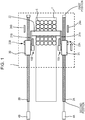
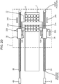
- a transport apparatus includes moving members 3A and 3B, shafts 21A and 21B, a contact member 22, and air dampers 10A and 10B.
- the moving members 3A and 3B are moved along a table 7 where articles 5 are to be disposed.
- the shafts 21A and 21 B are rotatably connected to the respective moving members 3A and 3B.
- the contact member 22 is connected to the shafts 21A and 21 B so as to be brought into contact with the articles 5.
- the air dampers 10A and 10B attenuate kinetic energy of the contact member 22 and the shafts 21A and 21B while the contact member 22 and the shafts 21A and 21 B are being moved down toward the table 7.
- the transport apparatus may further include, for example, bar-shaped members 2A and 2B that are disposed parallel to the table 7 and include respective magnetic bodies.
- the moving members 3A and 3B may each include a portion that includes a magnetic body and faces part of a side surface of a corresponding one of the bar-shaped members 2A and 2B.
- the transport apparatus may further include drive devices 4A and 4B that rotate the respective bar-shaped members 2A and 2B about the respective central axes of the bar-shaped members 2A and 2B so as to move the moving members 3A and 3B along the respective bar-shaped members 2A and 2B.
- the moving members 3A and 3B are moved along the table 7 in a range between a first position and a second position.
- the transport apparatus further includes inhibiting mechanisms 23A and 23B and dogs 24A and 24B.
- the inhibiting mechanisms 23A and 23B are respectively provided in the moving members 3A and 3B and inhibit rotation of the shafts 21A and 21B, thereby to hold the contact member 22 above the articles 5.
- the dogs 24A and 24B are brought into contact with the respective inhibiting mechanisms 23A and 23B at specified positions so as to release the inhibition of the rotation of the shafts 21A and 21B, the inhibition being performed by the inhibiting mechanisms 23A and 23B, thereby allowing the contact member 22 to move down toward the table 7.
- the chamber 1 is, for example, a temperature controlled chamber having a space in which the articles 5 are to be disposed and the temperature of which is controlled.
- the temperature controlled chamber may be, for example, a freeze drying chamber.
- the articles 5 are, for example, vials or the like into which pharmaceuticals are injected.
- the chamber 1 is a freeze drying chamber, the articles 5 are to be disposed on the table 7 in the chamber, so that the pharmaceuticals or the like in the articles 5 are to be freeze dried.
- the table 7 is, for example, a shelf board.
- a heat sterilizer may be provided in the chamber 1.
- the cylindrical bar-shaped member 2A is held by a bearing.
- the bar-shaped member 2A is a magnetic screw that includes a hard magnetic body and that has an outer circumferential surface on which a helical S-pole magnetized zone and a helical N-pole magnetized zone are disposed parallel to each other.
- the bar-shaped member 2A may be inserted into a non-magnetic thin pipe 20A of a body.
- the pipe 20A is formed of, for example, stainless steel.
- the bar-shaped member 2A and the pipe 20A are integrated with each other, so that, when the bar-shaped member 2A is rotated, the pipe 20A is also rotated about the central axis of the bar-shaped member 2A.
- the moving member 3A includes a magnetic nut including a hard magnetic body and has a hole having a larger inner circumference than an outer circumference of the bar-shaped member 2A.
- the bar-shaped member 2A is inserted through the nut-shaped hole of the moving member 3A.
- a helical S-pole magnetized zone and a helical N-pole magnetized zone are disposed parallel to each other on an inner circumferential surface of the moving member 3A.
- the pitch of the magnetized zones of the moving member 3A is substantially the same as the pitch of the magnetized zones of the bar-shaped member 2A.
- Guide rings 31 and 32 such as bushings may be provided at the inner circumferential surface of the moving member 3A.
- the inner circumferences of the guide rings 31 and 32 are each smaller than the inner circumference of the moving member 3A and is in contact with the outer circumference of the pipe 20A. Thus, a gap of a certain distance is maintained between the magnetized zones of the bar-shaped member 2A and the magnetized zones of the moving member 3A.
- the guide rings 31 and 32 are formed of a material having a small coefficient of friction such as, for example, a fluorocarbon polymer.
- the cylindrical bar-shaped member 2B is held by a bearing such that the bar-shaped member 2B is parallel to the bar-shaped member 2A.
- the structure of the bar-shaped member 2B is the same as or similar to that of the bar-shaped member 2A.
- the structure of the moving member 3B is the same as or similar to that of the moving member 3A.
- the drive devices 4A and 4B include, for example, rotating motors and are disposed outside a temperature controlled space of the chamber 1.
- the drive devices 4A and 4B may be disposed outside a housing of the chamber 1 or at respective positions that are in the housing of the chamber 1 and outside the temperature controlled space.
- the drive devices 4A and 4B may be covered with a shield or the like that prevents dispersion of dust or the like that may be generated.
- the drive device 4A and the second position side of the bar-shaped member 2A are connected to each other by, for example, a core rod.
- the drive device 4B and the second position side of the bar-shaped member 2B are connected to each other through, for example, a core rod.
- the drive devices 4A and 4B are in synchronization with each other to rotate the bar-shaped members 2A and 2B.
- the drive device 4A rotates the bar-shaped member 2A
- magnetic forces act between the magnetized zones of the bar-shaped member 2A and the magnetized zones of the moving member 3A.
- the moving member 3A which is connected to the moving member 3B through the shafts 21A and 21B and the contact member 22, cannot be rotated.
- the moving member 3A is moved along the central axis of the bar-shaped member 2A.
- the drive device 4B rotates the bar-shaped member 2B
- magnetic forces act between the magnetized zones of the bar-shaped member 2B and the magnetized zones of the moving member 3B, thereby the moving member 3B is moved along the central axis of the bar-shaped member 2B.
- the shafts 21A and 21B and the contact member 22 connected between the moving members 3A and 3B are also moved along the central axes of the bar-shaped members 2A and 2B.
- the contact member 22 is, for example, a plate-shaped or bar-shaped member.
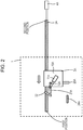
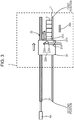
- the articles 5 in the chamber are transported to the outside of the chamber 1 as follows: as illustrated in Fig. 1 , Fig. 2 that is a side view seen from the table 7 side, and Fig. 3 that is a side view seen from the opposite side to the table 7, the contact member 22 connected to the moving members 3A and 3B passes through a region above the articles 5 toward the first position to a rear region of the chamber 1; as illustrated in Fig. 4 , Fig. 5 that is a side view seen from the table 7 side, and Fig.
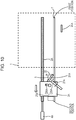
- the contact member 22 is moved down toward the table 7 in the rear region of the chamber 1; and after that, as illustrated in Figs. 7 to 10 , the contact member 22 is brought into contact with the articles 5 and pushes the articles 5 toward the second position, thereby transporting the articles 5 to the outside of the chamber 1.
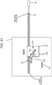
- the shaft 21A that holds the contact member 22 at one end portion is connected to the moving member 3A such that the shaft 21A is rotatable, for example, in a plane that is perpendicular to the surface of the table 7 and parallel to the central axis direction of the bar-shaped member 2A.
- the shaft 21B that holds the contact member 22 at the other end portion is connected to the moving member 3B such that, for example, the shaft 21B is rotatable in a plane that is perpendicular to the surface of the table 7 and parallel to the central axis direction of the bar-shaped member 2B.
- the inhibiting mechanism 23A provided in the moving member 3A inhibits the rotation of the shaft 21A so as to hold the contact member 22 above the articles 5 while the moving member 3A is moving toward the first position in the rear region of the chamber 1.
- the inhibiting mechanism 23A includes, for example, a first rotating member 25A and a second rotating member 26A.
- the first rotating member 25A is rotated when pushed by the dog 24A that is disposed at a specified position.
- the second rotating member becomes rotatable when the first rotating member 25A is rotated.
- the first rotating member 25A and the second rotating member 26A are rotated in a plane that is perpendicular to the surface of the table 7 and parallel to the central axis direction of the bar-shaped member 2A.
- the shaft 21A is connected to the second rotating member 26A.
- the shaft 21A and the second rotating member 26A share a rotational shaft.
- the moving member 3A is moving toward the first position at the rear region of the chamber 1
- the second rotating member 26A is held by the first rotating member 25A and unable to be rotated.
- the first rotating member 25A is pushed by the dog 24A secured at the specified position, rotated, and separated from the second rotating member 26A with which the first rotating member 25A has been in contact.
- the second rotating member 26A having been released from the inhibition of rotation by the first rotating member 25A is rotated due to gravity exerted on the shaft 21A and the contact member 22.
- the shaft 21A and the contact member 22 are moved down toward the table 7.
- the kinetic energy of the contact member 22 and the shafts 21A and 21B is attenuated by the air dampers 10A and 10B illustrated in Figs. 4 and 5 , thereby a crash force of the contact member 22 against the table 7 is reduced.
- the shapes of the first rotating member 25A and the second rotating member 26A illustrated in Fig. 6 are not particularly limited.
- the first rotating member 25A and the second rotating member 26A may have a rocker arm shape or a cam shape that at least has an elongated portion.
- the second rotating member 26A having been released from the inhibition of rotation by the first rotating member 25A is rotated so as to pass through, for example, the bottom dead center.
- the dog 24A has any shape as long as the dog 24A can cause the first rotating member 25A to rotate at the specified position.
- the rotational shaft of the first rotating member 25A may have rotational resistance that allows the rotational shaft of the first rotating member 25A to rotate when the first rotating member 25A is pushed by the dog 24A. Furthermore, the first rotating member 25A may have a weight that allows the first rotating member 25A to rotate when the first rotating member 25A is pushed by the dog 24A.
- the rotational resistance of the rotational shaft of the second rotating member 26A may be lower than the rotational resistance of the rotational shaft of the first rotating member 25A.
- the amount of rotation of the second rotating member 26A that becomes rotatable may be larger than the amount of rotation of the first rotating member 25A pushed by the dog 24A.
- the moving member 3A may be provided with a rotational angle regulators 27A that regulate the rotational angle of the first rotating member 25A.
- the inhibiting mechanism 23B provided in the moving member 3B illustrated in Fig. 4 has a structure that is the same as or similar to the structure of the inhibiting mechanism 23A provided in the moving member 3A.
- the inhibiting mechanism 23B is brought into contact with the dog 24B at the specified position so as to allow the shaft 21 B to be rotated.
- the dog 24A and the dog 24B are disposed at the same position in the central axis direction of the bar-shaped members 2A and 2B.
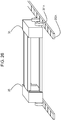
- the air damper 10A illustrated in Fig. 5 includes a piston rod 12A and a cylinder 11A.
- the piston rod 12A is rotatably connected to the shaft 21A.
- the cylinder 11A contains at least part of the piston rod 12A.
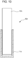
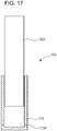
- the cylinder 11A is rotatably connected to the moving member 3A. While the contact member 22 and the shaft 21A are being moved down toward the table 7, the piston rod 12A is pushed by the shaft 21A, thereby, as illustrated in Figs. 12 and 13 , the piston rod 12A is moved toward a closed end portion of the cylinder 11A.
- the temperature in the chamber 1 illustrated in Fig. 1 may be increased for sterilization and decreased for freeze drying the articles 5.
- the cylinder 11A and the piston rod 12A illustrated in Fig. 12 may be exposed to high temperatures and low temperatures.
- the orifice between the side wall of the piston rod 12A and the inner wall of the cylinder 11A can be maintained at a fixed size even when the ambient temperature changes.
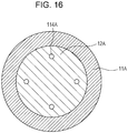
- grooves 112A may be provided in a side surface of the piston rod 12A. In this case, the gas in the cylinder 11A flows to the outside of the cylinder 11A through the grooves 112A.
- grooves 111A may be provided in the inner wall of the cylinder 11A. In this case, the gas in the cylinder 11A flows to the outside of the cylinder 11A through the grooves 111A.
- the piston rod 12A may have holes 114A that penetrate therethrough.
- the gas in the cylinder 11A flows to the outside of the cylinder 11A through the holes 114A provided in the piston rod 12A while the piston rod 12A is being moved toward the closed end portion of the cylinder 11A.
- the cylinder 11A may have holes 113A that penetrate through a side wall of the cylinder 11A.
- the gas in the cylinder 11A flows to the outside of the cylinder 11A through the holes 113A provided in the cylinder 11A while the piston rod 12A is being moved toward the closed end portion of the cylinder 11A.
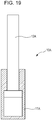
- the piston rod 12A may include a rod portion having a small diameter and a piston portion having a large diameter. Furthermore, as illustrated in Fig. 19 , the inner diameter of the cylinder 11A may be approximately the same as the outer diameter of the piston portion of the piston rod 12A on the closed end side and approximately the same as the outer diameter of the rod portion of the piston rod 12A on the open end side.
- the air damper 10B illustrated in Fig. 1 has a structure that is the same as or similar to the structure of the air damper 10A.
- the moving members 3A and 3B are moved toward the second position outside the chamber 1 and separated from the dogs 24A and 24B as illustrated in Figs. 7 to 10 .
- the articles 5 on the table 7 are pushed by the contact member 22, thereby being transported to the outside of the chamber 1.
- the shafts 21A and 21B and the contact member 22 may be moved upward to a specified height by a robot arm or a hand of an operator so as to inhibit rotation of the shafts 21A and 21B by using the inhibiting mechanisms 23A and 23B.
- the shafts 21A and the contact member 22 may be moved upward to a specified height as illustrated in Fig. 3 by a robot arm or a hand of an operator so as to inhibit rotation of the shafts 21A with the inhibiting mechanisms 23A.
- the structure of the transport apparatus according to the first embodiment having been described is not complex, the amount of dust generated while the contact member 22 is being moved down is small. Accordingly, it is possible to keep the inside of the chamber clean. Also, the maintenance of the chamber 1 and the transport apparatus is easy. Furthermore, since the structure is not complex, it is possible to suppress remaining of a washing solution after washing has been performed. Furthermore, in the transport apparatus according to the first embodiment, the contact member 22 is moved down by utilizing gravity. Accordingly, it is not necessary to move the motors into the chamber 1 for moving down the contact member 22 into the chamber 1. Thus, the temperature inside the chamber 1 is not increased by heat generation by the motors.
- drive transmission between the bar-shaped members 2A and 2B and the moving members 3A and 3B is performed by magnetic forces in a non-contact manner. This reduces likelihood of heat or dust being generated during drive transmission between the bar-shaped members 2A and 2B and the moving members 3A and 3B. Thus, even when the bar-shaped members 2A and 2B and the moving members 3A and 3B are disposed in the temperature controlled space of the chamber 1, the inside of the temperature controlled space is unlikely to be affected by heat or dust.
- the contact member 22 may crash onto the table 7 with a strong force. This may generate loud sounds or cause damage to components of the transport apparatus and the articles 5. Furthermore, when oil dampers are used, the oil dampers are unlikely to endure both a high-temperature environment for sterilization and a low-temperature environment for freeze drying. Furthermore, when the articles 5 are pharmaceuticals or the like, leakage of oil from the oil dampers is not allowed.
- a cushioning member such as a rubber stopper or the like is disposed at the bottom surface of the contact member 22, the cushioning member cannot reduce energy of the contact member 22 while the contact member 22 is being moved down toward the table 7. Furthermore, when the cushioning member is deformed, it is difficult to move down the contact member 22 to a specified position. Furthermore, when a cushioning member such as a rubber stopper is used, fragments of rubber or the like may scatter as foreign matter.
- the transport apparatus according to the first embodiment which includes the air dampers 10A and 10B, can suppress crashing of the contact member 22 onto the table 7 with a large force. Furthermore, the air dampers 10A and 10B can endure both the high-temperature environment for sterilization and the low-temperature environment for freeze drying. Furthermore, there is no possibility of scattering of foreign matter such as oil or fragments of rubber from the air dampers 10A and 10B.
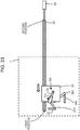
- the air damper 10A includes the cylinder 11A rotatably connected to the shaft 21A and the piston rod 12A at least part of which is contained in the cylinder 11A.
- the piston rod 12A is rotatably connected to the moving member 3A. While the contact member 22 and the shafts 21A and 21B are being moved down toward the table 7, the closed end portion of the cylinder 11A is moved toward the end of the piston rod 12A.
- the air damper 10B has a structure that is the same as or similar to the structure of the air damper 10A.
- Other elements of the transport apparatus according to the second embodiment are the same as or similar to those of the transport apparatus according to the first embodiment. Also with the transport apparatus according to the second embodiment, the kinetic energy of the contact member 22 and the shafts 21A and 21B is attenuated, thereby the crash force of the contact member 22 against the table 7 is reduced.
- the structures of the bar-shaped member 2A and the moving member 3A are not limited to the examples illustrated in Fig. 11 .
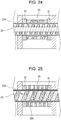
- the bar-shaped member 2A may be a soft magnetic body having a thread ridge.
- the structure of the moving member 3A is the same as or similar to the structure illustrated in Fig. 11 .
- the pitch of the thread ridge of the bar-shaped member 2A illustrated in Fig. 24 is substantially the same as the pitch of the magnetized zones of the moving member 3A.
- the bar-shaped member 2A having the thread ridge may be inserted into the non-magnetic thin pipe 20A. This can prevent foreign matter from adhering to a thread groove of the bar-shaped member 2A.
- magnetic forces act between the thread ridge of the bar-shaped member 2A and the magnetized zones of the moving member 3A, thereby the moving member 3A is moved.
- the moving member 3A may include a soft magnetic body having a thread ridge.
- the surface of a recess of the moving member 3A where the thread ridge is provided may be covered with a non-magnetic thin pipe 30A. This can prevent foreign matter from adhering to a thread groove of the moving member 3A.
- the structure of the bar-shaped member 2A is the same as or similar to the structure illustrated in Fig. 11 .
- the pitch of the thread ridge of the moving member 3A illustrated in Fig. 25 is substantially the same as the pitch of the magnetized zones of the bar-shaped member 2A.
- the articles to be transported into or from the chamber are not limited to articles including pharmaceuticals.
- the articles may include, for example, food, beverages, and precision components, and any other article.
- the chamber is not limited to a freeze drying chamber.
- the chamber may be a fermentation chamber or any kind of chamber for which suppression of an uneven distribution of an inner temperature and generation of dust is desired.
- the shape of the moving member is not limited to a nut shape.
- the shape of the moving member may be a recess shape. In this case, the bar-shaped member is moved in a recess of a recess-shaped moving member.
- An S-pole magnetized zone and an N-pole magnetized zone are disposed parallel to each other on a side surface of the recess of the recess-shaped moving member.
- the moving members 3A and 3B are driven by magnetic screws.
- the moving member 3A may be able to be self propelled and include wheels 201A rotatable on a track 202A and a drive device 203A that rotates the wheels 201A. Shafts of the wheels 201A may be held by bearings 207A.
- the drive device 203A may be controlled by a controller 204A. Furthermore, content of control performed by the controller 204A may be remotely indicated from the outside through a receiver 205A.
- the moving member 3A may include therein a battery 206A that supplies power to the drive device 203A and so force.
Landscapes
- Engineering & Computer Science (AREA)
- Mechanical Engineering (AREA)
- General Engineering & Computer Science (AREA)
- Transmission Devices (AREA)
- Special Conveying (AREA)
- Drying Of Solid Materials (AREA)
Applications Claiming Priority (1)
| Application Number | Priority Date | Filing Date | Title |
|---|---|---|---|
| JP2016240545A JP2018095389A (ja) | 2016-12-12 | 2016-12-12 | 搬送装置 |
Publications (1)
| Publication Number | Publication Date |
|---|---|
| EP3333101A1 true EP3333101A1 (de) | 2018-06-13 |
Family
ID=60673305
Family Applications (1)
| Application Number | Title | Priority Date | Filing Date |
|---|---|---|---|
| EP17206800.9A Withdrawn EP3333101A1 (de) | 2016-12-12 | 2017-12-12 | Transportvorrichtung |
Country Status (4)
| Country | Link |
|---|---|
| US (1) | US20180162656A1 (de) |
| EP (1) | EP3333101A1 (de) |
| JP (1) | JP2018095389A (de) |
| CN (1) | CN108225028A (de) |
Families Citing this family (1)
| Publication number | Priority date | Publication date | Assignee | Title |
|---|---|---|---|---|
| DE102021113060A1 (de) * | 2021-05-20 | 2022-11-24 | Khs Gmbh | Vorrichtung und Verfahren zur Handhabung und/oder Gruppierung von Stückgütern |
Citations (6)
| Publication number | Priority date | Publication date | Assignee | Title |
|---|---|---|---|---|
| US3827549A (en) * | 1973-03-16 | 1974-08-06 | Hunter Automated Mach Corp | Extended cooling conveyor |
| DE2451548B1 (de) * | 1974-10-30 | 1976-04-29 | Keller & Co C | Einrichtung zum bilden von lagen aus ziegelformlingen oder ziegeln |
| US20020104740A1 (en) * | 2001-02-02 | 2002-08-08 | Franke Walter K. | Conveyor system pusher having equalized motion |
| US7695230B2 (en) | 2003-02-22 | 2010-04-13 | Gea Lyophil Gmbh | Apparatus for loading and unloading freeze-drying chambers |
| CA2817557A1 (fr) * | 2013-05-22 | 2014-11-22 | Gebo Packaging Solutions Italy S.R.L. | Palettiseur, procede de palettisation et transfert par le palettiseur d'une couche d'objets d'un convoyeur vers un outil de depose. |
| JP2016090075A (ja) | 2014-10-30 | 2016-05-23 | アズビル株式会社 | 温度管理装置、搬送装置、及び搬送台 |
-
2016
- 2016-12-12 JP JP2016240545A patent/JP2018095389A/ja active Pending
-
2017
- 2017-12-12 EP EP17206800.9A patent/EP3333101A1/de not_active Withdrawn
- 2017-12-12 CN CN201711318046.8A patent/CN108225028A/zh not_active Withdrawn
- 2017-12-12 US US15/838,641 patent/US20180162656A1/en not_active Abandoned
Patent Citations (6)
| Publication number | Priority date | Publication date | Assignee | Title |
|---|---|---|---|---|
| US3827549A (en) * | 1973-03-16 | 1974-08-06 | Hunter Automated Mach Corp | Extended cooling conveyor |
| DE2451548B1 (de) * | 1974-10-30 | 1976-04-29 | Keller & Co C | Einrichtung zum bilden von lagen aus ziegelformlingen oder ziegeln |
| US20020104740A1 (en) * | 2001-02-02 | 2002-08-08 | Franke Walter K. | Conveyor system pusher having equalized motion |
| US7695230B2 (en) | 2003-02-22 | 2010-04-13 | Gea Lyophil Gmbh | Apparatus for loading and unloading freeze-drying chambers |
| CA2817557A1 (fr) * | 2013-05-22 | 2014-11-22 | Gebo Packaging Solutions Italy S.R.L. | Palettiseur, procede de palettisation et transfert par le palettiseur d'une couche d'objets d'un convoyeur vers un outil de depose. |
| JP2016090075A (ja) | 2014-10-30 | 2016-05-23 | アズビル株式会社 | 温度管理装置、搬送装置、及び搬送台 |
Also Published As
| Publication number | Publication date |
|---|---|
| CN108225028A (zh) | 2018-06-29 |
| US20180162656A1 (en) | 2018-06-14 |
| JP2018095389A (ja) | 2018-06-21 |
Similar Documents
| Publication | Publication Date | Title |
|---|---|---|
| US10384888B2 (en) | Temperature management apparatus, transfer apparatus, and transfer base | |
| Niu et al. | An investigation on the occurrence of stable cage whirl motions in ball bearings based on dynamic simulations | |
| JP6038589B2 (ja) | 直動案内装置 | |
| EP2251564A1 (de) | Kugeldrehzahlreduzierer und drehtellervorrichtung damit | |
| BR9909071A (pt) | Método de acionamento por parafuso e aparelho | |
| KR20120112612A (ko) | 이재장치 및 공작물 재치장치 | |
| EP3333101A1 (de) | Transportvorrichtung | |
| US4440038A (en) | Lead screw and follower assembly | |
| JP2016136033A5 (de) | ||
| Larsen-Basse | Basic theory of solid friction. | |
| BR102012000930A8 (pt) | aparelho para processar peças de trabalho | |
| US20240183428A1 (en) | Discrete roller assembly-based helical drive for translation | |
| DE112014006700B4 (de) | Transportsystem | |
| US8820547B2 (en) | Movable rack unit | |
| JPH11201256A (ja) | アクチュエータ | |
| DE2658925C3 (de) | Notlauflager für schnellaufende Drehkörper | |
| KR101525056B1 (ko) | 비접촉식 이송 가이드 | |
| US10703575B2 (en) | Conveyance device | |
| Xu et al. | Modeling and analyzing the slipping of the ball screw | |
| CN108883881B (zh) | 输送装置及存储装置 | |
| JP2602002B2 (ja) | 搬送位置決め装置 | |
| JP2017125601A (ja) | 直動テーブル | |
| Cai et al. | Study on jamming mechanism of the planetary roller screw mechanism | |
| Alaci et al. | Determination of the coefficient of friction using spinning motion | |
| NL1044553B1 (en) | Electromagnetic Linear Stage for cryogenic environment |
Legal Events
| Date | Code | Title | Description |
|---|---|---|---|
| PUAI | Public reference made under article 153(3) epc to a published international application that has entered the european phase |
Free format text: ORIGINAL CODE: 0009012 |
|
| AK | Designated contracting states |
Kind code of ref document: A1 Designated state(s): AL AT BE BG CH CY CZ DE DK EE ES FI FR GB GR HR HU IE IS IT LI LT LU LV MC MK MT NL NO PL PT RO RS SE SI SK SM TR |
|
| AX | Request for extension of the european patent |
Extension state: BA ME |
|
| STAA | Information on the status of an ep patent application or granted ep patent |
Free format text: STATUS: THE APPLICATION IS DEEMED TO BE WITHDRAWN |
|
| 18D | Application deemed to be withdrawn |
Effective date: 20181214 |