EP3332065B1 - Kranmatratze - Google Patents
Kranmatratze Download PDFInfo
- Publication number
- EP3332065B1 EP3332065B1 EP15900604.8A EP15900604A EP3332065B1 EP 3332065 B1 EP3332065 B1 EP 3332065B1 EP 15900604 A EP15900604 A EP 15900604A EP 3332065 B1 EP3332065 B1 EP 3332065B1
- Authority
- EP
- European Patent Office
- Prior art keywords
- crane mat
- panel
- crane
- mat
- members
- Prior art date
- Legal status (The legal status is an assumption and is not a legal conclusion. Google has not performed a legal analysis and makes no representation as to the accuracy of the status listed.)
- Active
Links
Images






Classifications
-
- E—FIXED CONSTRUCTIONS
- E01—CONSTRUCTION OF ROADS, RAILWAYS, OR BRIDGES
- E01C—CONSTRUCTION OF, OR SURFACES FOR, ROADS, SPORTS GROUNDS, OR THE LIKE; MACHINES OR AUXILIARY TOOLS FOR CONSTRUCTION OR REPAIR
- E01C9/00—Special pavings; Pavings for special parts of roads or airfields
- E01C9/08—Temporary pavings
- E01C9/086—Temporary pavings made of concrete, wood, bitumen, rubber or synthetic material or a combination thereof
-
- B—PERFORMING OPERATIONS; TRANSPORTING
- B66—HOISTING; LIFTING; HAULING
- B66C—CRANES; LOAD-ENGAGING ELEMENTS OR DEVICES FOR CRANES, CAPSTANS, WINCHES, OR TACKLES
- B66C23/00—Cranes comprising essentially a beam, boom, or triangular structure acting as a cantilever and mounted for translatory of swinging movements in vertical or horizontal planes or a combination of such movements, e.g. jib-cranes, derricks, tower cranes
- B66C23/62—Constructional features or details
- B66C23/72—Counterweights or supports for balancing lifting couples
- B66C23/78—Supports, e.g. outriggers, for mobile cranes
-
- E—FIXED CONSTRUCTIONS
- E01—CONSTRUCTION OF ROADS, RAILWAYS, OR BRIDGES
- E01C—CONSTRUCTION OF, OR SURFACES FOR, ROADS, SPORTS GROUNDS, OR THE LIKE; MACHINES OR AUXILIARY TOOLS FOR CONSTRUCTION OR REPAIR
- E01C5/00—Pavings made of prefabricated single units
- E01C5/22—Pavings made of prefabricated single units made of units composed of a mixture of materials covered by two or more of groups E01C5/008, E01C5/02 - E01C5/20 except embedded reinforcing materials
-
- E—FIXED CONSTRUCTIONS
- E04—BUILDING
- E04B—GENERAL BUILDING CONSTRUCTIONS; WALLS, e.g. PARTITIONS; ROOFS; FLOORS; CEILINGS; INSULATION OR OTHER PROTECTION OF BUILDINGS
- E04B5/00—Floors; Floor construction with regard to insulation; Connections specially adapted therefor
- E04B5/02—Load-carrying floor structures formed substantially of prefabricated units
-
- E—FIXED CONSTRUCTIONS
- E04—BUILDING
- E04C—STRUCTURAL ELEMENTS; BUILDING MATERIALS
- E04C2/00—Building elements of relatively thin form for the construction of parts of buildings, e.g. sheet materials, slabs, or panels
- E04C2/02—Building elements of relatively thin form for the construction of parts of buildings, e.g. sheet materials, slabs, or panels characterised by specified materials
- E04C2/10—Building elements of relatively thin form for the construction of parts of buildings, e.g. sheet materials, slabs, or panels characterised by specified materials of wood, fibres, chips, vegetable stems, or the like; of plastics; of foamed products
- E04C2/12—Building elements of relatively thin form for the construction of parts of buildings, e.g. sheet materials, slabs, or panels characterised by specified materials of wood, fibres, chips, vegetable stems, or the like; of plastics; of foamed products of solid wood
-
- E—FIXED CONSTRUCTIONS
- E04—BUILDING
- E04C—STRUCTURAL ELEMENTS; BUILDING MATERIALS
- E04C2/00—Building elements of relatively thin form for the construction of parts of buildings, e.g. sheet materials, slabs, or panels
- E04C2/30—Building elements of relatively thin form for the construction of parts of buildings, e.g. sheet materials, slabs, or panels characterised by the shape or structure
- E04C2/40—Building elements of relatively thin form for the construction of parts of buildings, e.g. sheet materials, slabs, or panels characterised by the shape or structure composed of a number of smaller components rigidly or movably connected together, e.g. interlocking, hingedly connected of particular shape, e.g. not rectangular of variable shape or size, e.g. flexible or telescopic panels
Definitions
- This application relates generally to the field of temporary roadways and/or ground protection, and more particularly to crane mats and methods and systems for their manufacture.
- US2014/341649 discloses a nut to be used as part of a fastener that can be used, for example, in the manufacture of wood crane mats.
- US9068434 discloses an end cap assembly for a tri-layer oiled field support mat usable to support trucks, equipment and personnel around a drilling rig.
- US8066447 discloses wood mats formed of layers of timbers, a method and apparatus for assembling wood mats.
- US8382393 relates to a temporary roadway with a static resistant synthetic inter-connectable structural mat.
- US4462712 relates to a constructions site flooring system formed of a plurality of interlocking floor units.
- US4600336 relates to reusable wooden mat units which can be easily transported and interlocked with other like units.
- US1465383 relates to composite lumber and a method of forming the same.
- a crane mat according to the invention is defined in the appended claims.
- an embodiment of a crane mat comprising a plurality of panels positioned in alternating transverse directions with respect to one another.
- Each of the panels is laminated to an adjacent one of the panels, and each of the panels comprise a plurality of lumber members positioned sided by side.
- the plurality of lumber members of each panel are oriented in either a longitudinal direction or a transverse direction of the crane mat.
- the plurality of lumber members in a top panel and a bottom panel of the crane mat are oriented in the transverse direction, which is parallel to a direction of travel of vehicular traffic thereon.
- the top and bottom panels include a plurality of spaced apart grooves extending longitudinally from a first longitudinal end of the crane mat to a second longitudinal end of the crane mat for enhancing traction of a vehicle when traversing across the crane mat.
- the plurality of grooves are positioned longitudinally along a portion of the top and bottom panels of the crane mat.
- the crane mat includes an edge protector removably.
- the plurality of panels may include a softwood species, a hardwood species, or any combination of the softwood and the hardwood species. At least one of the plurality of lumber members in the top and bottom panels may include a hardwood species. At least one of the plurality of lumber members in at least one of the panels positioned between the top and bottom panels may include a softwood species.
- the hardwood species may include at least one of oak, maple, hickory, hackberry, and cherry, and the softwood species may include at least one of spruce, pine, fir, southern yellow pine, and hemlock.
- the plurality of lumber members in at least one of the panels may include a plurality of different widths of lumber positioned side-by-side. At least one of the plurality of lumber members may include a plurality of wooden members fingerjointed together.
- the spaced apart grooves in the top and bottom panels may comprise a depth up to at least approximately one half of a thickness of a respective one of the top and bottom panel.
- the depth of the spaced apart grooves may vary from the first longitudinal end of the crane mat to the second longitudinal end of the crane mat.
- At least one of the spaced apart grooves comprises a depth that may vary from the first longitudinal end of the crane mat to the second longitudinal end of the crane mat.
- the edge protector may include a plastic.
- the edge protector may include a chamfer positioned along top and bottom longitudinal edges.
- Each of the longitudinal protrusions of the edge protector may include a trapezoidal cross section to ease installation and removal of the edge protector on the top and bottom panels of the crane mat.
- crane mats of the instant disclosure may be positioned on the ground for use in the creation of a temporary roadway or platform for vehicles, cranes, construction equipment, and other mobile or stationary machinery.
- crane mats of the instant disclosure are configured for placement on the ground with the long side of each crane mat positioned transverse to the direction of travel of the crane or vehicle thereon.
- Additional crane mats of the instant disclosure may be positioned in the same orientation with respect to one another, with respective long sides of adjacent crane mats lying adjacent to one another.
- Crane mats of the instant disclosure may be combined with other mats of different configurations to account for variations in the stability of the ground.
- crane mats of the instant disclosure may be positioned across timber mats to account for relatively unstable terrain.
- An offset pattern can also be created in the field where crane mats of the instant disclosure are all oriented in the same direction but are positioned in a laterally overlapping manner with longitudinal ends of adjacent crane mats positioned offset to one another.
- the relatively shorter side of the crane mats of the instant disclosure being oriented in the direction of travel of the crane or vehicle best approximates the contour of the ground. As a result, tilting or other undesired movement of each crane mat will be minimized as a crane, for example, travels over a temporary roadway formed from a plurality of crane mats of the instant disclosure.
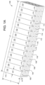
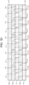
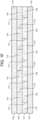
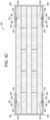
- FIG. 1A-1F , 2A-2B , 3A-3C , and 4A-4B illustrate exemplary embodiments and methods of manufacture of a crane mat comprising a plurality of panels for use in the creation of a temporary roadway or platform for vehicles, cranes, construction equipment, and other mobile or stationary machinery.
- crane mat 100 includes panels 102,104,106,108,110.
- crane mat 100 is configured with a plurality of panels with a maximum of thirteen panels to provide a desired strength and/or operating performance.
- panel 102 is positioned on top of panel 104, which is positioned on top of panel 106, which is positioned on top of panel 108, which is positioned on top of panel 110.
- panel 110 may be positioned on top of panel 108, which may be positioned on top of panel 106, which may be positioned on top of panel 104, which may be positioned on top of panel 102.
- crane mat 100 is fully reversible, with either of panels 102 or 110 acting as the working surface for receiving vehicles, cranes, construction equipment or other mobile or stationary machinery, and with the other of panels 102 or 110 being configured for placement on, for example, the ground, a roadway, a ramp, a platform or other crane mat or object.
- panel 102 is glued to panel 104
- panel 104 is glued to panel 106
- panel 106 is glued to panel 108
- panel 108 is glued to panel 110.
- each of panels 102,106,110 is oriented in a first direction and panels 104,108 are oriented in a second direction approximately 90 degrees relative to panels 102,106,110.
- at least two adjacent panels of the crane mat are aligned in approximately the same direction (see, e.g., Figs. 1C-1F ).
- the overall strength and rigidity of crane mat 100 is likely maximized, however, by alternating the direction of respective adjacent panel layers.
- each of panels 102,106,110 includes a plurality of members 112 positioned side-by-side along respective side ends 115.
- Each member 112, and particularly each side end 115 of each member 112, is oriented in the first direction.
- the first direction is oriented parallel to the general direction of travel of vehicular traffic on crane mat 100.
- the length "L1" of each member 112 is longer than a width "W1" of each member 112, and the width of each member 112 is longer than a depth or height "H1" of each member 112.
- each member 112 is shown in the figures as being of the same length "L1," in other embodiments, for each member 112, the length "L1" thereof may comprise a plurality of separate members that together result in achieving the length "L1" for each member 112.
- the combination of members that form each member 112 may vary in length from one to another.
- each of panels 104,108 includes a plurality of members 114 positioned side-by-side along respective side ends 117.
- Each member 114, and particularly each side end 117 of each member 114, is oriented in the second direction.
- the length "L2" of each member 114 is longer than a width "W2" of each member 114, and the width of each member 114 is longer than a depth or height "H2" of each member 114. Consequently, the length of each member 114 of each of panels 104,108 is oriented in the second direction, which is 90 degrees relative to the first direction and transverse to the general direction of travel of vehicular traffic on crane mat 100.
- the length of members 114 is greater than the length of members 112, whereas the width and height of members 114 and members 112 are approximately the same as one another.
- members 114 are shown in the figures as being of the same length "L2,” in other embodiments, for each member 114, the length "L2" thereof may comprise a plurality of separate members that together result in achieving the length "L2" for each member 114.
- the combination of members that form each member 114 may vary in length from one to another.
- members 114 are generally aligned in a longitudinal direction (i.e., the second direction) of crane mat 100, and members 112 are generally aligned transverse (i.e., in the first direction) to members 114.
- the length of members 114 defines the longitudinal length of crane mat 100
- the length of members 112 defines the transverse width of crane mat 100, where length "L2" is longer than length "L1".
- crane mat 100 is configured to be approximately 1.22 metres (4 feet) wide in the first, transverse direction and 4.88 metres (16 feet) long in the second, longitudinal direction. In another embodiment, crane mat 100 is configured to be approximately 1.22 metres (4 feet) wide in the first, transverse direction and 5.49 metres (18 feet) long in the second, longitudinal direction. In another embodiment, crane mat 100 is configured to be approximately 1.22 metres (4 feet) wide in the first, transverse direction and 6.10 metres (20 feet) long in the second, longitudinal direction. In another embodiment, crane mat 100 is configured to be approximately 1.22 metres (4 feet) wide in the first, transverse direction and 6.71 metres (22 feet) long in the second, longitudinal direction.
- crane mat 100 is configured to be approximately 1.22 metres (4 feet) wide in the first, transverse direction and 7.32 metres (24 feet) long in the second, longitudinal direction. In other embodiments, crane mat 100 may have a width that is smaller or larger than 1.22 metres (4 feet) and a length that is shorter or longer than 4.88 metres (16 feet). In use, multiple crane mats 100 may be abutted adjacent one another or attached to one another along the long side of crane mat 100 to orient the short side of crane mat 100 and particularly members 112 so as to be positioned in the direction of vehicle movement. In this way, the long side of the crane mat is positioned to accommodate wide vehicles traveling parallel to the orientation of members 112.
- members 112 are glued to one another along respective side ends 115, and members 114 are glued to one another along respective side ends 117.
- each of members 112 is approximately the same geometry as one another in terms of width, depth, and length.
- each of members 114 is approximately the same geometry as one another in terms of width, depth, and length.
- members 112,114 may include dimensional lumber, including 1x4, 1x6, 1x8, 1x10, 1x12, 2x4, 2x6, 2x8, 2x10, and 2x12. In some embodiments, for any given panel, members 112,114 may comprise the same width of lumber positioned side-by-side to create the panel.
- Members 112,114 of one or more panels of crane mat 100 may include softwood lumber comprising, for example, spruce, pine, fir, southern yellow pine, or hemlock, hardwood lumber comprising, for example, oak, maple, hickory, hackberry, or cherry, or any combination of softwood or hardwood.
- a hardwood species such as oak
- a softwood species such as pine
- a hardwood panel comprising members 112 or 114 may comprise hardwood lumber 2.5cm (1 inch) thick with lumber comprising different widths positioned side-by-side.
- a softwood panel comprising members 112 or 114 may comprise softwood lumber 5.1cm (2 inches) thick with lumber comprising different widths positioned side-by-side.
- a panel made of one or more hardwood species of lumber may be positioned adjacent above or below and glued to a panel made of one or more softwood species of lumber.
- members 112,114 may include any material in any stock dimension suitable for creating a temporary roadway, including a plastic, a composite, or a metal.
- FIGs. 1C-1D there is shown a crane mat 100.
- panel 106 is replaced by panel 111 having a plurality of members 114 positioned side-by-side along respective side ends 117.
- Each member 114 of panel 111 is oriented in a longitudinal direction (i.e., the second direction) of crane mat 100.
- each of members 114 of panel 111 are positioned laterally offset in the first direction relative to respective members 114 in adjacent panels 104,108.
- the offset side ends 117 of members 114 of respective panels 104,111,108 provide enhanced lateral stiffness of crane mat 100 in the first direction while permitting enhanced longitudinal flexibility in the second direction than the embodiment of crane mat 100 shown in Figs. 1A-1B .
- Figs. 1E-1F show yet another crane mat 100.
- Panels 106,108 are replaced in their entirety by panel 111 having a plurality of members 114 positioned side-by-side along respective side ends 117 to form a four panel crane mat 100.
- each member 114 of panel 111 is oriented in a longitudinal direction (i.e., the second direction) of crane mat 100.
- each of members 114 of panel 111 are positioned laterally offset in the first direction relative to respective members 114 in adjacent panel 104.
- the offset side ends 117 of members 114 of respective panels 104,111 provide enhanced lateral stiffness of crane mat 100 while permitting enhanced longitudinal flexibility than the embodiment of crane mat 100 shown in Figs.
- the embodiment of Figs. 1E-1F provides the added benefits of: (1) reduced fabrication costs due to less material and fewer manufacturing processes needed to produce crane mat 100; (2) reduced transportation costs due to lighter weight finished product and smaller finished product volume, which permits shipping more crane mat units in a single freight transportation container, and (3) easier handling by users due to lighter weight of the finished product.
- Crane mat 200 includes all of the same features, characteristics, and variations described above for crane mat 100 with the addition of a plurality of slots or grooves 201 disposed on the top panel 202 and/or bottom panel 210 of crane mat 200 for enhancing vehicle traction when traversing across crane mat 200 parallel to the orientation of members 212.
- panels 202,204,206,208,210 of crane mat 200 are identical to panels 102,104,106,108,110 of crane mat 100 except that panel 202 is shown as including grooves 201 disposed thereon.
- crane mat 100 may include grooves 201 as described in more detail below.
- grooves 201 may comprise generally vertical opposing sidewalls 205 and a generally horizontal bottom wall 203.
- grooves 201 may comprise a Li-shape (with or without a rounded bottom wall), a V-shape, a trapezoidal shape, a semi-circular shape, or any other shape or combination thereof that enhances vehicle traction.
- crane mat 200 includes 9 slots or grooves 201 positioned on top panel 202 (and bottom panel 210 to provide reversibility of crane mat 200), though a greater or fewer quantity of grooves 201 are possible.
- Grooves 201 may comprise any width and any spacing that permits a desired number of grooves 201 to be positioned on panel 202,210. Grooves 201 may comprise any depth up to at least approximately one half of the thickness of panel 202. In one embodiment, grooves 201 comprise a depth from about 0.025 metres (0.100") to about 0.019 metres (0.75"). In one embodiment, grooves 201 comprise a depth of about 0.006 metres (0.25") +/- 0.004 metres (0.150"). In another embodiment, grooves 201 comprise a depth of about 0.013 metres (0.50"). In another embodiment, grooves 201 comprise a depth of about 0.019 metres (0.75").
- Grooves may vary in depth from one end of crane mat 200 to another end of crane mat to enhance drainage of water from crane mat 200.
- Grooves 201 may also vary in depth from any point along crane mat 200 relative to any other point along crane mat 200. For example, the depth of grooves 201 may be more shallow in the middle of crane mat 200 and progressively deeper toward the periphery to enhance drainage of water from crane mat 200.
- grooves 201 are generally aligned in a longitudinal direction of crane mat 200 and transverse to members 212, which are generally aligned transverse to members 214.
- the length of members 214 defines the longitudinal length of crane mat 200
- the length of members 212 define the transverse width of crane mat 200.
- grooves 201 will be oriented to maximize resistance to wear and damage that may be caused by vehicular traffic over crane mat 200 while grooves 201 provide for rain, moisture, mud or other debris to collect therein and drain therefrom to enhance traction of the vehicle.
- grooves 201 may be oriented in any angle on panel 202 and/or 210. In some embodiments, the angle of grooves 201 relative to other grooves 201 form a pattern on panel 202 and/or 210.
- Crane mat 300 includes all of the same features, characteristics, and variations described above for crane mat 100 with the addition of a plurality of slots or grooves 301,311 disposed on the top panel 302 and/or bottom panel 310 of crane mat 300.
- panels 302,304,306,308,310 of crane mat 300 are identical to panels 102,104,106,108,110 of crane mat 100 except that panel 302 is shown as including grooves 301,311 disposed thereon.
- crane mat 100 may include grooves 301,311 as described in more detail below.
- grooves 301 are disposed along the first and last members 312 on top panel 302 and/or the first and last members 312 on bottom panel 310 near the periphery of crane mat 300.
- Grooves 301 provide a means for attaching accessories for joining adjacent mats together and for handling and manipulation of crane mat 300 at, for example, the job site.
- Grooves 301 may also provide a means for engaging with an embodiment of protectors 350 (discussed below) for protecting at least a portion of a longitudinal end of crane mat 300 during handling and use.
- grooves 301 are shown as extending along a portion of members 312. In other embodiments, grooves 301 may extend from one end to the other end of member 312.
- grooves 311 are disposed on top panel 302 and bottom panel 310 longitudinally and transverse to members 312, which are generally aligned transverse to members 314, near the periphery of crane mat 300. Grooves 311 extend along a portion of the periphery of crane mat 300 for limiting the longitudinal motion of protectors 350 (discussed below) when engaged thereto.
- Grooves 311 may comprise generally vertical opposing sidewalls 305 and a generally horizontal bottom wall 303. In other embodiments, grooves 311 may comprise a U-shape (with or without a rounded bottom wall), a V-shape, a trapezoidal shape, a semi-circular shape, or any other shape or combination thereof that enables engagement with protrusions 355 of protectors 350. Grooves 311 may comprise any depth up to approximately one half of the thickness of panel 302,310. In one embodiment, grooves 311 comprise a depth from about 0.0025 metres (0.100") to about 0.019 metres (0.75"). In one embodiment, grooves 311 comprise a depth of about 0.006 metres (0.25") +/- 0.004 metres (0.150"). In another embodiment, grooves 311 comprise a depth of about 0.013 metres (0.50"). In another embodiment, grooves 311 comprise a depth of about 0.019 metres (0.75").
- crane mat 300 also includes protectors 350 that are removably positionable along the longitudinal sides of crane mat 300.
- Protectors 350 are configured for protecting at least a portion of a longitudinal side of crane mat 300 during handling and use.
- crane mat 300 includes two protectors 350.
- crane mat 300 may include a greater or fewer number of protectors 350, and crane mat 300 may include a greater or fewer number of grooves 311.
- Protectors 350 may include a longitudinal chamfer 360 of sufficient size along top and bottom outer edges to permit, for example, a forklift operator to easily insert a forklift blade between two adjacently positioned crane mats 300 having protectors 350 thereon and to separate the two crane mats 300 for subsequent lifting or handling operations.
- Protectors 350 may comprise a Li-shape to mount over at least a portion of a longitudinal side of crane mat 300. In other embodiments, protectors 350 may be configured to mount over at least a portion of a transverse side of crane mat 300. In such embodiments, protectors 350 may be configured to engage with grooves 301. In this embodiment, protectors 350 are configured for attachment to crane mat 300 via protrusions 355 that are configured to engage with grooves 311. In other embodiments, protectors 350 are configured for attachment to crane mat 300 via an interference fit with crane mat 300.
- protrusions 355 are configured with at least one longitudinal chamfer 365 to permit relatively easy installation and removal of protectors 350 from crane mat 300 when, for example, damage to protector 350 occurs necessitating its replacement.
- protrusions 355 have a trapezoidal cross sectional shape.
- Protectors 350 may be fabricated from any plastic, including polyethylene, polypropylene, polystyrene, polyamide, polyvinyl chloride, and polycarbonate. Protectors 350 may be fabricated from any metal, including steel and aluminum. Protectors 350 may be fabricated from any composite material, including fiber reinforced plastics and metal composites. Protectors 350 may be fabricated from extrusions, injection moldings, stampings, laminations, forgings, castings, and the like.
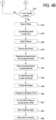
- Figs. 4A- 4B there is shown one embodiment of a method of making a crane mat of the present disclosure comprising an apparatus or system 400.
- system 400 can be manufactured by system 400 using the method disclosed herein.
- one or more aspects of system 400 can be merged with one another, omitted, or made part of additional apparatuses or system components.
- These systems may be configured to fabricate a crane mat billet, which may be further cut or trimmed to meet customer specifications.
- System 400 is configured to stack lumber at Step 414 according to size for later retrieval.
- system 400 loads a composite sheet for a carrier apparatus of system 400, after which lumber is loaded side-by-side for a bottom panel of a crane mat at Step 418.
- System 400 may be configured to apply glue to a top surface of the bottom panel in a manner that minimizes adhesive material cost, which may otherwise be a significant expense in the construction of a crane mat.
- the panel is moved or conveyed under a stationary glue dispensing apparatus while glue is dispensed from the glue dispensing apparatus onto the panel.
- the panel is held stationary while the glue dispensing apparatus traverses over the panel and dispenses glue onto the panel.
- a continuous (or in some embodiments a discontinuous) ribbon of glue is applied along the perimeter of a given panel while a solid or a stitched pattern of rows of adhesive is applied to the interior, central area of the top surface of the panel.
- system 400 includes stationary adhesive nozzles (or other glue dispensing apparatus) positioned in a row transverse to the longitudinal orientation of the panel.
- system 400 at Step 420 applies a solid glue line along the lateral and longitudinal perimeter of the top surface of the bottom panel while system 400 at Step 422 simultaneously applies a solid and/or a stitched or intermittent glue line along the central area of the top surface of the bottom panel. If a stitched or intermittent glue line is applied, the interval between glue dots or dashes in the central area is dependent on the speed at which the panel is conveyed under the nozzles as well as the pulse duration of the dispensing of glue from the nozzles.
- system 400 includes traversing adhesive nozzles (or other glue dispensing apparatus) positioned in a row transverse to the longitudinal orientation of the panel. As the adhesive nozzles traverse over the stationary panel, system 400 at Step 420 applies a solid glue line along the lateral and longitudinal perimeter of the top surface of the bottom panel while system 400 at Step 422 simultaneously applies a solid and/or a stitched or intermittent glue line along the central area of the top surface of the bottom panel. If a stitched or intermittent glue line is applied, the interval between glue dots or dashes in the central area is dependent on the speed at which the adhesive nozzles traverse over the panel as well as the pulse duration of the dispensing of glue from the nozzles.
- Step 424 the same glue application technique is performed by system 400 to the next succeeding panel, which will be oriented transverse to the bottom panel, and which is stacked upon the bottom panel.
- the load, stacking, and gluing process of Steps 418, 420, 422, and 424 is repeated at Steps 426 and 428 for the additional panels that will be stacked to form the desired crane mat.
- An assembled plurality of laminated, composite panels of a crane mat are then stacked on top of an additional plurality of composite panels of separate crane mats at Steps 430, 432, 434, and 436 and all are pressed in a press system of system 400 at Step 438.
- 3 or 4 sets of crane mats may be pressed at one time in this way. In other embodiments, a greater or fewer number of crane mats may be pressed at the same time.
- the composite panels are removed from the press system of system 400 and separated from one another.
- the composite panels of a particular crane mat are cut by one or more cutting machines of system 400 to a desired finished length and width.
- the various edges of the crane mat may optionally be beveled by system 400.
- one or more routers or plunge cutters of system 400 are configured to cut optional grooves 301,311 discussed above on either or both of the top or bottom surfaces of the crane mat.
- one or more routers or plunge cutters of system 400 are configured to cut optional grooves 201 on either or both of the top or bottom surfaces of the crane mat.
- system 400 is configured to optionally paint or seal one or more sides of the crane mat.
- the completed crane mat having the desired configuration is moved to inventory.
- One or more aspects of system 400 are operable by one or more computers and/or one or more programmable logic controllers (PLC's).
- the computers and/or PLC's may be coupled with one or more sensors configured for reporting position, measurements, status, and other data regarding elements of system 400 and the crane mats being fabricated, and motors, actuators and the like for controlling the operation of one or more aspects of system 400.
- the computers and/or PLC's may be connected to one another and to other computers or devices via a wired or wireless network. These devices may be connected to one or more remote computers and/or web servers via a wired or wireless connection to the Internet.
- the computers and one or more PLC's include a processor, such as a central processing unit (CPU), for executing software, particularly software stored in memory or on any computer readable medium, for use by or in connection with any computer related system or method.
- a processor such as a central processing unit (CPU)
- CPU central processing unit
- software particularly software stored in memory or on any computer readable medium, for use by or in connection with any computer related system or method.
- a computer readable medium includes any electronic, magnetic, optical, or other physical device or apparatus that can contain or store a computer program for use by or in connection with a computer related system or method.
- Memory can include any one or a combination of volatile memory elements (e.g., random access memory (RAM, such as DRAM, SRAM, SDRAM, etc.)) and nonvolatile memory elements (e.g., ROM, hard drive, tape, CDROM, etc.).
- RAM random access memory
- nonvolatile memory elements e.g., ROM, hard drive, tape, CDROM, etc.
- memory may incorporate electronic, magnetic, optical, and/or other types of storage media.
- Memory can have a distributed architecture where various components are situated remote from one another, but are still accessed by a processor.
- the software may include one or more separate programs comprising ordered listings of executable instructions for implementing logical functions.
- the software stored in memory or on any computer readable medium may include one or more computer programs, each including executable instructions executed by the processor.
- An operating system may control the execution of other computer programs and can provide scheduling, input-output control, file and data management, memory management, and communication control and related services.
- the PLC may include a computer processor such as a central processing unit (CPU), memory, operating software stored in memory, and various input and output (I/O) devices or data paths.
- the I/O devices may include input devices, such as a keyboard, mouse, touch screen, and/or any other user interface.
- the I/O devices may also include output devices, such as a computer display, a modem, a router, serial and parallel wired and wireless communication components and any other elements needed to connect to, for example, another computer or device via a local network or the Internet whether wired or wirelessly.
- the I/O devices may further include any element or device in a feedback control system for controlling the operation and performance of any aspect of system 400.
Landscapes
- Engineering & Computer Science (AREA)
- Architecture (AREA)
- Civil Engineering (AREA)
- Structural Engineering (AREA)
- Life Sciences & Earth Sciences (AREA)
- Wood Science & Technology (AREA)
- Mechanical Engineering (AREA)
- Physics & Mathematics (AREA)
- Electromagnetism (AREA)
- Jib Cranes (AREA)
- Conveying And Assembling Of Building Elements In Situ (AREA)
- Dry Formation Of Fiberboard And The Like (AREA)
Claims (4)
- Kranmatratze, umfassend:eine Vielzahl von Feldern (102-110), die miteinander verklebt und in abwechselnden Quer- und Längsrichtungen zueinander ausgerichtet sind, wobei jedes der Felder mit einem angrenzenden der Felder laminiert ist und umfassend eine Vielzahl von Holzelementen (112, 114; 212, 214; 312, 314), die nebeneinander positioniert und entlang jeweiliger Seitenenden (115, 117) miteinander verklebt sind, wobei die Vielzahl von Holzelementen jedes Felds entweder in einer Längsrichtung oder einer Querrichtung der Kranmatratze ausgerichtet ist; wobeidie Vielzahl von Holzelementen (112; 212; 312) in einem oberen Feld (102; 202; 302) und einem unteren Feld (110; 210; 310) der Kranmatratze in der Querrichtung der Kranzmatratze ausgerichtet sind,wobei die Kranmatratze (100; 200; 300) vollständig reversibel ist, wobei beide der oberen und der unteren Felder als die Arbeitsoberfläche wirken; undwobei die Breite und die Höhe der Vielzahl von Holzelementen (112; 114; 212; 214; 312; 314) von jedem Feld (102-110) untereinander etwa gleich ist; und wobei eine Länge jedes der Vielzahl von Holzelementen in dem oberen Feld (102; 202; 302) beziehungsweise dem unteren Feld(110; 210; 310) derart geringer als eine Länge jedes jeweiligen der Vielzahl von Holzelementen (114) in einem Zwischenfeld angrenzend an das obere Feld ist, dass die Matratze in der Längsrichtung größer als in der Querrichtung ist.
- Kranmatratze nach Anspruch 1, wobei die Vielzahl von Feldern (102-110) eine Weichholzart, eine Hartholzart oder eine beliebige Kombination aus der Weichholz- und der Hartholzart umfasst.
- Kranmatratze nach Anspruch 2, wobei die Vielzahl von Feldern (102-110) die Weichholzart umfasst und wobei die Weichholzart mindestens eines von Fichte, Kiefer, Tanne, Fichtenkiefer und Schierlingstanne umfasst.
- Kranmatratze nach Anspruch 1, wobei die Vielzahl von Holzelementen in mindestens einem der Felder eine Vielzahl von Breiten von Holz umfasst, die nebeneinander positioniert sind.
Applications Claiming Priority (3)
| Application Number | Priority Date | Filing Date | Title |
|---|---|---|---|
| US201562200508P | 2015-08-03 | 2015-08-03 | |
| US201562211651P | 2015-08-28 | 2015-08-28 | |
| PCT/US2015/058990 WO2017023347A1 (en) | 2015-08-03 | 2015-11-04 | Crane mat and method of manufacture |
Publications (3)
| Publication Number | Publication Date |
|---|---|
| EP3332065A1 EP3332065A1 (de) | 2018-06-13 |
| EP3332065A4 EP3332065A4 (de) | 2019-01-16 |
| EP3332065B1 true EP3332065B1 (de) | 2024-01-03 |
Family
ID=57943352
Family Applications (1)
| Application Number | Title | Priority Date | Filing Date |
|---|---|---|---|
| EP15900604.8A Active EP3332065B1 (de) | 2015-08-03 | 2015-11-04 | Kranmatratze |
Country Status (5)
| Country | Link |
|---|---|
| US (1) | US20170037581A1 (de) |
| EP (1) | EP3332065B1 (de) |
| CA (3) | CA2994742C (de) |
| MX (1) | MX2018001480A (de) |
| WO (1) | WO2017023347A1 (de) |
Families Citing this family (4)
| Publication number | Priority date | Publication date | Assignee | Title |
|---|---|---|---|---|
| US10577753B2 (en) | 2015-08-03 | 2020-03-03 | Sterling Site Access Solutions, Llc | Crane mat and method of manufacture |
| CA3052949C (en) * | 2017-02-08 | 2024-05-21 | Sterling Lumber Company, Llc | Crane mat and method of manufacture |
| US10273638B1 (en) | 2018-03-26 | 2019-04-30 | Quality Mat Company | Laminated mats with closed and strengthened core layer |
| RU203717U1 (ru) * | 2020-12-28 | 2021-04-16 | Общество с ограниченной ответственностью "Амитекс" | Щит-подушка под слиток файнштейна |
Citations (1)
| Publication number | Priority date | Publication date | Assignee | Title |
|---|---|---|---|---|
| US1465383A (en) * | 1920-03-17 | 1923-08-21 | Frank J Walsh | Composite lumber |
Family Cites Families (34)
| Publication number | Priority date | Publication date | Assignee | Title |
|---|---|---|---|---|
| US2699578A (en) * | 1950-03-08 | 1955-01-18 | Estle H Marks | Door construction |
| US2819026A (en) * | 1953-12-17 | 1958-01-07 | Leyendecker John Battice | Road construction |
| US2912909A (en) * | 1954-10-01 | 1959-11-17 | Andrew P Hart | Portable road and turn-around |
| US3348459A (en) * | 1967-01-03 | 1967-10-24 | Harvey Aluminum Inc | Interlocking matting and coupling bar therefor |
| US3658622A (en) * | 1969-04-09 | 1972-04-25 | Georgia Pacific Corp | Process for making wood laminate |
| US3752396A (en) * | 1971-07-16 | 1973-08-14 | L Bustin | Traction mat |
| US3715882A (en) * | 1971-07-16 | 1973-02-13 | H Ohde | Clock cabinet |
| US3730820A (en) * | 1971-07-19 | 1973-05-01 | W Fields | Softwood-hardwood laminated panel |
| US4289420A (en) * | 1979-06-06 | 1981-09-15 | Davis Marvin L | Wooden mat |
| US4462712A (en) * | 1981-07-16 | 1984-07-31 | Quality Mat Company | Method and apparatus for a construction site flooring system |
| US4600337A (en) * | 1983-10-31 | 1986-07-15 | Sarver Ronald D | Board mat system |
| US4600336A (en) * | 1984-03-09 | 1986-07-15 | Waller Jr A J | Interlocking wooden mat |
| US4875800A (en) * | 1988-01-22 | 1989-10-24 | Way Construction, Inc. | Temporary support surfaces for use on muddy or marshy land areas |
| US4919480A (en) * | 1989-09-22 | 1990-04-24 | Drew Iii James H | Sectional bench |
| US5393166A (en) * | 1993-05-10 | 1995-02-28 | Target Recycling Inc. | Reflective marker from recyclable material |
| US5496648A (en) * | 1994-11-04 | 1996-03-05 | Held; Russell K. | Formable composite laminates with cellulose-containing polymer resin sheets |
| US5833196A (en) * | 1995-04-17 | 1998-11-10 | Keith; George A. | Desk top mat |
| US5822944A (en) * | 1996-09-04 | 1998-10-20 | Penland, Sr.; Joe E. | Double locking flooring system for a construction site |
| CA2267156A1 (en) * | 1996-10-18 | 1998-04-30 | Jarkko Valtanen | Protective structure |
| US6007271A (en) * | 1998-09-09 | 1999-12-28 | American Landfill Management, Inc. | Ground pressure distribution mat and method of use |
| US6474905B1 (en) * | 2001-08-07 | 2002-11-05 | Clarence R. Smith, Jr. | Temporary support structure |
| US8066447B2 (en) * | 2006-08-03 | 2011-11-29 | Randel Brandstrom | Wood mat and apparatus and method for assembling same |
| AT11958U1 (de) * | 2010-09-07 | 2011-08-15 | Hans-Peter Ing Leitinger | Verfahren zur verarbeitung von roh-rundholz und keilverzinkte holzverbundprodukte |
| US20120317905A1 (en) * | 2011-06-14 | 2012-12-20 | Macduff Matthew | Load-bearing member with hollow fastener |
| US8382393B1 (en) * | 2011-06-17 | 2013-02-26 | Hb Green Resources, Llc | Temporary roadway for moving heavy equipment on an incline and steep grades including synthetic inter-connectable movable and removable structural mats |
| US8936073B1 (en) * | 2011-06-17 | 2015-01-20 | Hb Green Resources, Llc | Drilling rig with a static resistant synthetic inter-connectable structural mat |
| US8966692B2 (en) * | 2011-09-30 | 2015-03-03 | Crawford Dewar | Bridge composite structural panel |
| US9068434B1 (en) | 2012-06-04 | 2015-06-30 | Hb Green Resources, Llc | Interconnecting end caps for an oil field mat system |
| US20140270937A1 (en) * | 2013-03-15 | 2014-09-18 | Sabic Innovative Plastics Ip B.V. | Road barrier energy absorber mechanism |
| US10392234B2 (en) | 2013-05-16 | 2019-08-27 | Axion Structural Innovations, Llc | Nut and a method of use of the nut in a fastener system for crane mats |
| AU2014273930A1 (en) * | 2013-05-30 | 2015-12-17 | Mike WOLD | Modular rig mat system |
| CA2843105A1 (en) * | 2014-02-20 | 2015-08-20 | Structurlam Products Ltd. | Access mat |
| US9546455B2 (en) * | 2014-10-23 | 2017-01-17 | Dean Forbes | Rig mat with replaceable deck inserts |
| US20160355993A1 (en) * | 2015-06-03 | 2016-12-08 | The Modern Group, Ltd. | Crane mat |
-
2015
- 2015-11-04 US US14/932,329 patent/US20170037581A1/en not_active Abandoned
- 2015-11-04 WO PCT/US2015/058990 patent/WO2017023347A1/en not_active Ceased
- 2015-11-04 CA CA2994742A patent/CA2994742C/en active Active
- 2015-11-04 MX MX2018001480A patent/MX2018001480A/es unknown
- 2015-11-04 CA CA3201987A patent/CA3201987C/en active Active
- 2015-11-04 EP EP15900604.8A patent/EP3332065B1/de active Active
- 2015-11-04 CA CA3201979A patent/CA3201979A1/en active Pending
Patent Citations (1)
| Publication number | Priority date | Publication date | Assignee | Title |
|---|---|---|---|---|
| US1465383A (en) * | 1920-03-17 | 1923-08-21 | Frank J Walsh | Composite lumber |
Also Published As
| Publication number | Publication date |
|---|---|
| MX2018001480A (es) | 2018-08-15 |
| WO2017023347A1 (en) | 2017-02-09 |
| EP3332065A4 (de) | 2019-01-16 |
| US20170037581A1 (en) | 2017-02-09 |
| CA2994742C (en) | 2023-09-26 |
| CA3201987A1 (en) | 2017-02-09 |
| CA3201979A1 (en) | 2017-02-09 |
| EP3332065A1 (de) | 2018-06-13 |
| CA2994742A1 (en) | 2017-02-09 |
| CA3201987C (en) | 2026-03-10 |
Similar Documents
| Publication | Publication Date | Title |
|---|---|---|
| CA2994742C (en) | Crane mat and method of manufacture | |
| US10273638B1 (en) | Laminated mats with closed and strengthened core layer | |
| US4289420A (en) | Wooden mat | |
| US9605390B2 (en) | Industrial mats having cost effective core support structures | |
| US6474905B1 (en) | Temporary support structure | |
| US10753050B2 (en) | Industrial mats having cost effective core structures | |
| US20120063844A1 (en) | Engineered laminated horizontal glulam beam | |
| US11566385B2 (en) | Crane mat and method of manufacture | |
| US9447547B2 (en) | Mat construction with environmentally resistant core | |
| US10017903B2 (en) | Industrial mats having side protection | |
| CA2980896A1 (en) | Mat construction with environmentally resistant core | |
| JP5939727B1 (ja) | 湾曲積層材ブロック及びその製造方法、並びに湾曲積層材ブロックを用いた構造壁の製造方法 | |
| EP3580056B1 (de) | Verfahren zur herstellung einer kranmatratze | |
| US6938321B2 (en) | Pallet scuffing apparatus | |
| WO2007083988A2 (en) | Paper pallets, boards and the like | |
| WO2020014156A1 (en) | Industrial mats having cost effective core structures | |
| US20160235234A1 (en) | Laminated mat with endcap | |
| EP4353649B1 (de) | Verfahren zur verpackung von aufzugskomponenten einer kompletten aufzugsanlage | |
| DE10117955C2 (de) | Palette zum Transport von Plattentapeln | |
| JP2026043764A (ja) | 床構造 | |
| DE202004007541U1 (de) | Aufnahme für zu Großgebinden zusammengefaßten Waren beim Transport oder der Lagerung | |
| AU7152000A (en) | Pallet angle | |
| BG97500A (bg) | Палета от рифелован материал |
Legal Events
| Date | Code | Title | Description |
|---|---|---|---|
| STAA | Information on the status of an ep patent application or granted ep patent |
Free format text: STATUS: THE INTERNATIONAL PUBLICATION HAS BEEN MADE |
|
| PUAI | Public reference made under article 153(3) epc to a published international application that has entered the european phase |
Free format text: ORIGINAL CODE: 0009012 |
|
| STAA | Information on the status of an ep patent application or granted ep patent |
Free format text: STATUS: REQUEST FOR EXAMINATION WAS MADE |
|
| 17P | Request for examination filed |
Effective date: 20180202 |
|
| AK | Designated contracting states |
Kind code of ref document: A1 Designated state(s): AL AT BE BG CH CY CZ DE DK EE ES FI FR GB GR HR HU IE IS IT LI LT LU LV MC MK MT NL NO PL PT RO RS SE SI SK SM TR |
|
| AX | Request for extension of the european patent |
Extension state: BA ME |
|
| DAV | Request for validation of the european patent (deleted) | ||
| DAX | Request for extension of the european patent (deleted) | ||
| A4 | Supplementary search report drawn up and despatched |
Effective date: 20181213 |
|
| RIC1 | Information provided on ipc code assigned before grant |
Ipc: E04B 5/02 20060101ALI20181207BHEP Ipc: E01C 9/08 20060101AFI20181207BHEP Ipc: E01C 5/22 20060101ALI20181207BHEP Ipc: E04C 2/12 20060101ALI20181207BHEP Ipc: B66C 23/78 20060101ALI20181207BHEP Ipc: E04C 2/40 20060101ALI20181207BHEP |
|
| STAA | Information on the status of an ep patent application or granted ep patent |
Free format text: STATUS: EXAMINATION IS IN PROGRESS |
|
| 17Q | First examination report despatched |
Effective date: 20190809 |
|
| RAP3 | Party data changed (applicant data changed or rights of an application transferred) |
Owner name: STERLING SITE ACCESS SOLUTIONS, LLC |
|
| GRAP | Despatch of communication of intention to grant a patent |
Free format text: ORIGINAL CODE: EPIDOSNIGR1 |
|
| STAA | Information on the status of an ep patent application or granted ep patent |
Free format text: STATUS: GRANT OF PATENT IS INTENDED |
|
| INTG | Intention to grant announced |
Effective date: 20230803 |
|
| GRAS | Grant fee paid |
Free format text: ORIGINAL CODE: EPIDOSNIGR3 |
|
| GRAA | (expected) grant |
Free format text: ORIGINAL CODE: 0009210 |
|
| STAA | Information on the status of an ep patent application or granted ep patent |
Free format text: STATUS: THE PATENT HAS BEEN GRANTED |
|
| AK | Designated contracting states |
Kind code of ref document: B1 Designated state(s): AL AT BE BG CH CY CZ DE DK EE ES FI FR GB GR HR HU IE IS IT LI LT LU LV MC MK MT NL NO PL PT RO RS SE SI SK SM TR |
|
| REG | Reference to a national code |
Ref country code: GB Ref legal event code: FG4D |
|
| REG | Reference to a national code |
Ref country code: CH Ref legal event code: EP |
|
| REG | Reference to a national code |
Ref country code: DE Ref legal event code: R096 Ref document number: 602015087178 Country of ref document: DE |
|
| REG | Reference to a national code |
Ref country code: IE Ref legal event code: FG4D |
|
| P01 | Opt-out of the competence of the unified patent court (upc) registered |
Effective date: 20240213 |
|
| REG | Reference to a national code |
Ref country code: LT Ref legal event code: MG9D |
|
| PG25 | Lapsed in a contracting state [announced via postgrant information from national office to epo] |
Ref country code: ES Free format text: LAPSE BECAUSE OF FAILURE TO SUBMIT A TRANSLATION OF THE DESCRIPTION OR TO PAY THE FEE WITHIN THE PRESCRIBED TIME-LIMIT Effective date: 20240103 |
|
| PG25 | Lapsed in a contracting state [announced via postgrant information from national office to epo] |
Ref country code: ES Free format text: LAPSE BECAUSE OF FAILURE TO SUBMIT A TRANSLATION OF THE DESCRIPTION OR TO PAY THE FEE WITHIN THE PRESCRIBED TIME-LIMIT Effective date: 20240103 |
|
| REG | Reference to a national code |
Ref country code: NL Ref legal event code: MP Effective date: 20240103 |
|
| REG | Reference to a national code |
Ref country code: AT Ref legal event code: MK05 Ref document number: 1646896 Country of ref document: AT Kind code of ref document: T Effective date: 20240103 |
|
| PG25 | Lapsed in a contracting state [announced via postgrant information from national office to epo] |
Ref country code: NL Free format text: LAPSE BECAUSE OF FAILURE TO SUBMIT A TRANSLATION OF THE DESCRIPTION OR TO PAY THE FEE WITHIN THE PRESCRIBED TIME-LIMIT Effective date: 20240103 |
|
| PG25 | Lapsed in a contracting state [announced via postgrant information from national office to epo] |
Ref country code: NL Free format text: LAPSE BECAUSE OF FAILURE TO SUBMIT A TRANSLATION OF THE DESCRIPTION OR TO PAY THE FEE WITHIN THE PRESCRIBED TIME-LIMIT Effective date: 20240103 |
|
| PG25 | Lapsed in a contracting state [announced via postgrant information from national office to epo] |
Ref country code: IS Free format text: LAPSE BECAUSE OF FAILURE TO SUBMIT A TRANSLATION OF THE DESCRIPTION OR TO PAY THE FEE WITHIN THE PRESCRIBED TIME-LIMIT Effective date: 20240503 |
|
| PG25 | Lapsed in a contracting state [announced via postgrant information from national office to epo] |
Ref country code: LT Free format text: LAPSE BECAUSE OF FAILURE TO SUBMIT A TRANSLATION OF THE DESCRIPTION OR TO PAY THE FEE WITHIN THE PRESCRIBED TIME-LIMIT Effective date: 20240103 |
|
| PG25 | Lapsed in a contracting state [announced via postgrant information from national office to epo] |
Ref country code: GR Free format text: LAPSE BECAUSE OF FAILURE TO SUBMIT A TRANSLATION OF THE DESCRIPTION OR TO PAY THE FEE WITHIN THE PRESCRIBED TIME-LIMIT Effective date: 20240404 |
|
| PG25 | Lapsed in a contracting state [announced via postgrant information from national office to epo] |
Ref country code: RS Free format text: LAPSE BECAUSE OF FAILURE TO SUBMIT A TRANSLATION OF THE DESCRIPTION OR TO PAY THE FEE WITHIN THE PRESCRIBED TIME-LIMIT Effective date: 20240403 Ref country code: HR Free format text: LAPSE BECAUSE OF FAILURE TO SUBMIT A TRANSLATION OF THE DESCRIPTION OR TO PAY THE FEE WITHIN THE PRESCRIBED TIME-LIMIT Effective date: 20240103 |
|
| PG25 | Lapsed in a contracting state [announced via postgrant information from national office to epo] |
Ref country code: AT Free format text: LAPSE BECAUSE OF FAILURE TO SUBMIT A TRANSLATION OF THE DESCRIPTION OR TO PAY THE FEE WITHIN THE PRESCRIBED TIME-LIMIT Effective date: 20240103 Ref country code: CZ Free format text: LAPSE BECAUSE OF FAILURE TO SUBMIT A TRANSLATION OF THE DESCRIPTION OR TO PAY THE FEE WITHIN THE PRESCRIBED TIME-LIMIT Effective date: 20240103 |
|
| PG25 | Lapsed in a contracting state [announced via postgrant information from national office to epo] |
Ref country code: RS Free format text: LAPSE BECAUSE OF FAILURE TO SUBMIT A TRANSLATION OF THE DESCRIPTION OR TO PAY THE FEE WITHIN THE PRESCRIBED TIME-LIMIT Effective date: 20240403 Ref country code: NO Free format text: LAPSE BECAUSE OF FAILURE TO SUBMIT A TRANSLATION OF THE DESCRIPTION OR TO PAY THE FEE WITHIN THE PRESCRIBED TIME-LIMIT Effective date: 20240403 Ref country code: LT Free format text: LAPSE BECAUSE OF FAILURE TO SUBMIT A TRANSLATION OF THE DESCRIPTION OR TO PAY THE FEE WITHIN THE PRESCRIBED TIME-LIMIT Effective date: 20240103 Ref country code: IS Free format text: LAPSE BECAUSE OF FAILURE TO SUBMIT A TRANSLATION OF THE DESCRIPTION OR TO PAY THE FEE WITHIN THE PRESCRIBED TIME-LIMIT Effective date: 20240503 Ref country code: HR Free format text: LAPSE BECAUSE OF FAILURE TO SUBMIT A TRANSLATION OF THE DESCRIPTION OR TO PAY THE FEE WITHIN THE PRESCRIBED TIME-LIMIT Effective date: 20240103 Ref country code: GR Free format text: LAPSE BECAUSE OF FAILURE TO SUBMIT A TRANSLATION OF THE DESCRIPTION OR TO PAY THE FEE WITHIN THE PRESCRIBED TIME-LIMIT Effective date: 20240404 Ref country code: CZ Free format text: LAPSE BECAUSE OF FAILURE TO SUBMIT A TRANSLATION OF THE DESCRIPTION OR TO PAY THE FEE WITHIN THE PRESCRIBED TIME-LIMIT Effective date: 20240103 Ref country code: BG Free format text: LAPSE BECAUSE OF FAILURE TO SUBMIT A TRANSLATION OF THE DESCRIPTION OR TO PAY THE FEE WITHIN THE PRESCRIBED TIME-LIMIT Effective date: 20240103 Ref country code: AT Free format text: LAPSE BECAUSE OF FAILURE TO SUBMIT A TRANSLATION OF THE DESCRIPTION OR TO PAY THE FEE WITHIN THE PRESCRIBED TIME-LIMIT Effective date: 20240103 |
|
| PG25 | Lapsed in a contracting state [announced via postgrant information from national office to epo] |
Ref country code: PT Free format text: LAPSE BECAUSE OF FAILURE TO SUBMIT A TRANSLATION OF THE DESCRIPTION OR TO PAY THE FEE WITHIN THE PRESCRIBED TIME-LIMIT Effective date: 20240503 Ref country code: PL Free format text: LAPSE BECAUSE OF FAILURE TO SUBMIT A TRANSLATION OF THE DESCRIPTION OR TO PAY THE FEE WITHIN THE PRESCRIBED TIME-LIMIT Effective date: 20240103 |
|
| PG25 | Lapsed in a contracting state [announced via postgrant information from national office to epo] |
Ref country code: SE Free format text: LAPSE BECAUSE OF FAILURE TO SUBMIT A TRANSLATION OF THE DESCRIPTION OR TO PAY THE FEE WITHIN THE PRESCRIBED TIME-LIMIT Effective date: 20240103 Ref country code: PT Free format text: LAPSE BECAUSE OF FAILURE TO SUBMIT A TRANSLATION OF THE DESCRIPTION OR TO PAY THE FEE WITHIN THE PRESCRIBED TIME-LIMIT Effective date: 20240503 Ref country code: PL Free format text: LAPSE BECAUSE OF FAILURE TO SUBMIT A TRANSLATION OF THE DESCRIPTION OR TO PAY THE FEE WITHIN THE PRESCRIBED TIME-LIMIT Effective date: 20240103 Ref country code: LV Free format text: LAPSE BECAUSE OF FAILURE TO SUBMIT A TRANSLATION OF THE DESCRIPTION OR TO PAY THE FEE WITHIN THE PRESCRIBED TIME-LIMIT Effective date: 20240103 |
|
| REG | Reference to a national code |
Ref country code: DE Ref legal event code: R097 Ref document number: 602015087178 Country of ref document: DE |
|
| PG25 | Lapsed in a contracting state [announced via postgrant information from national office to epo] |
Ref country code: DK Free format text: LAPSE BECAUSE OF FAILURE TO SUBMIT A TRANSLATION OF THE DESCRIPTION OR TO PAY THE FEE WITHIN THE PRESCRIBED TIME-LIMIT Effective date: 20240103 |
|
| PG25 | Lapsed in a contracting state [announced via postgrant information from national office to epo] |
Ref country code: SM Free format text: LAPSE BECAUSE OF FAILURE TO SUBMIT A TRANSLATION OF THE DESCRIPTION OR TO PAY THE FEE WITHIN THE PRESCRIBED TIME-LIMIT Effective date: 20240103 |
|
| PG25 | Lapsed in a contracting state [announced via postgrant information from national office to epo] |
Ref country code: EE Free format text: LAPSE BECAUSE OF FAILURE TO SUBMIT A TRANSLATION OF THE DESCRIPTION OR TO PAY THE FEE WITHIN THE PRESCRIBED TIME-LIMIT Effective date: 20240103 |
|
| PG25 | Lapsed in a contracting state [announced via postgrant information from national office to epo] |
Ref country code: SK Free format text: LAPSE BECAUSE OF FAILURE TO SUBMIT A TRANSLATION OF THE DESCRIPTION OR TO PAY THE FEE WITHIN THE PRESCRIBED TIME-LIMIT Effective date: 20240103 |
|
| PG25 | Lapsed in a contracting state [announced via postgrant information from national office to epo] |
Ref country code: SM Free format text: LAPSE BECAUSE OF FAILURE TO SUBMIT A TRANSLATION OF THE DESCRIPTION OR TO PAY THE FEE WITHIN THE PRESCRIBED TIME-LIMIT Effective date: 20240103 Ref country code: SK Free format text: LAPSE BECAUSE OF FAILURE TO SUBMIT A TRANSLATION OF THE DESCRIPTION OR TO PAY THE FEE WITHIN THE PRESCRIBED TIME-LIMIT Effective date: 20240103 Ref country code: RO Free format text: LAPSE BECAUSE OF FAILURE TO SUBMIT A TRANSLATION OF THE DESCRIPTION OR TO PAY THE FEE WITHIN THE PRESCRIBED TIME-LIMIT Effective date: 20240103 Ref country code: EE Free format text: LAPSE BECAUSE OF FAILURE TO SUBMIT A TRANSLATION OF THE DESCRIPTION OR TO PAY THE FEE WITHIN THE PRESCRIBED TIME-LIMIT Effective date: 20240103 Ref country code: DK Free format text: LAPSE BECAUSE OF FAILURE TO SUBMIT A TRANSLATION OF THE DESCRIPTION OR TO PAY THE FEE WITHIN THE PRESCRIBED TIME-LIMIT Effective date: 20240103 |
|
| PLBE | No opposition filed within time limit |
Free format text: ORIGINAL CODE: 0009261 |
|
| STAA | Information on the status of an ep patent application or granted ep patent |
Free format text: STATUS: NO OPPOSITION FILED WITHIN TIME LIMIT |
|
| PG25 | Lapsed in a contracting state [announced via postgrant information from national office to epo] |
Ref country code: IT Free format text: LAPSE BECAUSE OF FAILURE TO SUBMIT A TRANSLATION OF THE DESCRIPTION OR TO PAY THE FEE WITHIN THE PRESCRIBED TIME-LIMIT Effective date: 20240103 |
|
| 26N | No opposition filed |
Effective date: 20241007 |
|
| PG25 | Lapsed in a contracting state [announced via postgrant information from national office to epo] |
Ref country code: IT Free format text: LAPSE BECAUSE OF FAILURE TO SUBMIT A TRANSLATION OF THE DESCRIPTION OR TO PAY THE FEE WITHIN THE PRESCRIBED TIME-LIMIT Effective date: 20240103 |
|
| PG25 | Lapsed in a contracting state [announced via postgrant information from national office to epo] |
Ref country code: SI Free format text: LAPSE BECAUSE OF FAILURE TO SUBMIT A TRANSLATION OF THE DESCRIPTION OR TO PAY THE FEE WITHIN THE PRESCRIBED TIME-LIMIT Effective date: 20240103 |
|
| REG | Reference to a national code |
Ref country code: CH Ref legal event code: PL |
|
| PG25 | Lapsed in a contracting state [announced via postgrant information from national office to epo] |
Ref country code: MC Free format text: LAPSE BECAUSE OF FAILURE TO SUBMIT A TRANSLATION OF THE DESCRIPTION OR TO PAY THE FEE WITHIN THE PRESCRIBED TIME-LIMIT Effective date: 20240103 |
|
| PG25 | Lapsed in a contracting state [announced via postgrant information from national office to epo] |
Ref country code: LU Free format text: LAPSE BECAUSE OF NON-PAYMENT OF DUE FEES Effective date: 20241104 |
|
| REG | Reference to a national code |
Ref country code: CH Ref legal event code: PL |
|
| GBPC | Gb: european patent ceased through non-payment of renewal fee |
Effective date: 20241104 |
|
| PG25 | Lapsed in a contracting state [announced via postgrant information from national office to epo] |
Ref country code: CH Free format text: LAPSE BECAUSE OF NON-PAYMENT OF DUE FEES Effective date: 20241130 |
|
| REG | Reference to a national code |
Ref country code: BE Ref legal event code: MM Effective date: 20241130 |
|
| PG25 | Lapsed in a contracting state [announced via postgrant information from national office to epo] |
Ref country code: FI Free format text: LAPSE BECAUSE OF FAILURE TO SUBMIT A TRANSLATION OF THE DESCRIPTION OR TO PAY THE FEE WITHIN THE PRESCRIBED TIME-LIMIT Effective date: 20240103 |
|
| PG25 | Lapsed in a contracting state [announced via postgrant information from national office to epo] |
Ref country code: BE Free format text: LAPSE BECAUSE OF NON-PAYMENT OF DUE FEES Effective date: 20241130 Ref country code: GB Free format text: LAPSE BECAUSE OF NON-PAYMENT OF DUE FEES Effective date: 20241104 |
|
| PGFP | Annual fee paid to national office [announced via postgrant information from national office to epo] |
Ref country code: DE Payment date: 20251126 Year of fee payment: 11 |
|
| PGFP | Annual fee paid to national office [announced via postgrant information from national office to epo] |
Ref country code: FR Payment date: 20251124 Year of fee payment: 11 |
|
| PGFP | Annual fee paid to national office [announced via postgrant information from national office to epo] |
Ref country code: IE Payment date: 20251118 Year of fee payment: 11 |
|
| PG25 | Lapsed in a contracting state [announced via postgrant information from national office to epo] |
Ref country code: HU Free format text: LAPSE BECAUSE OF FAILURE TO SUBMIT A TRANSLATION OF THE DESCRIPTION OR TO PAY THE FEE WITHIN THE PRESCRIBED TIME-LIMIT; INVALID AB INITIO Effective date: 20151104 |
|
| PG25 | Lapsed in a contracting state [announced via postgrant information from national office to epo] |
Ref country code: CY Free format text: LAPSE BECAUSE OF FAILURE TO SUBMIT A TRANSLATION OF THE DESCRIPTION OR TO PAY THE FEE WITHIN THE PRESCRIBED TIME-LIMIT; INVALID AB INITIO Effective date: 20151104 |