EP3330980A1 - Noyau de transformateur semi-hybride - Google Patents
Noyau de transformateur semi-hybride Download PDFInfo
- Publication number
- EP3330980A1 EP3330980A1 EP16201865.9A EP16201865A EP3330980A1 EP 3330980 A1 EP3330980 A1 EP 3330980A1 EP 16201865 A EP16201865 A EP 16201865A EP 3330980 A1 EP3330980 A1 EP 3330980A1
- Authority
- EP
- European Patent Office
- Prior art keywords
- limbs
- yoke
- transformer core
- steel
- grain
- Prior art date
- Legal status (The legal status is an assumption and is not a legal conclusion. Google has not performed a legal analysis and makes no representation as to the accuracy of the status listed.)
- Granted
Links
Images


Classifications
-
- H—ELECTRICITY
- H01—ELECTRIC ELEMENTS
- H01F—MAGNETS; INDUCTANCES; TRANSFORMERS; SELECTION OF MATERIALS FOR THEIR MAGNETIC PROPERTIES
- H01F27/00—Details of transformers or inductances, in general
- H01F27/24—Magnetic cores
- H01F27/26—Fastening parts of the core together; Fastening or mounting the core on casing or support
-
- H—ELECTRICITY
- H01—ELECTRIC ELEMENTS
- H01F—MAGNETS; INDUCTANCES; TRANSFORMERS; SELECTION OF MATERIALS FOR THEIR MAGNETIC PROPERTIES
- H01F3/00—Cores, Yokes, or armatures
- H01F3/02—Cores, Yokes, or armatures made from sheets
-
- H—ELECTRICITY
- H01—ELECTRIC ELEMENTS
- H01F—MAGNETS; INDUCTANCES; TRANSFORMERS; SELECTION OF MATERIALS FOR THEIR MAGNETIC PROPERTIES
- H01F27/00—Details of transformers or inductances, in general
- H01F27/24—Magnetic cores
- H01F27/245—Magnetic cores made from sheets, e.g. grain-oriented
-
- H—ELECTRICITY
- H01—ELECTRIC ELEMENTS
- H01F—MAGNETS; INDUCTANCES; TRANSFORMERS; SELECTION OF MATERIALS FOR THEIR MAGNETIC PROPERTIES
- H01F41/00—Apparatus or processes specially adapted for manufacturing or assembling magnets, inductances or transformers; Apparatus or processes specially adapted for manufacturing materials characterised by their magnetic properties
- H01F41/02—Apparatus or processes specially adapted for manufacturing or assembling magnets, inductances or transformers; Apparatus or processes specially adapted for manufacturing materials characterised by their magnetic properties for manufacturing cores, coils, or magnets
- H01F41/0206—Manufacturing of magnetic cores by mechanical means
- H01F41/0233—Manufacturing of magnetic circuits made from sheets
-
- H—ELECTRICITY
- H01—ELECTRIC ELEMENTS
- H01F—MAGNETS; INDUCTANCES; TRANSFORMERS; SELECTION OF MATERIALS FOR THEIR MAGNETIC PROPERTIES
- H01F3/00—Cores, Yokes, or armatures
- H01F3/10—Composite arrangements of magnetic circuits
- H01F2003/106—Magnetic circuits using combinations of different magnetic materials
Definitions
- the present disclosure relates to transformer cores, especially semi-hybrid transformer cores which combine parts of amorphous steel with parts of grain-oriented steel.
- transformers and shunt reactors are commonly the most expensive components in the power system and hence efficient design of these power devices could reduce the T&D losses.
- EP2685477 discloses a hybrid transformer core.
- the hybrid transformer core comprises a first yoke of amorphous steel and a second yoke of amorphous steel.
- the hybrid transformer core further comprises at least two limbs of grain-oriented steel extending between the first yoke and the second yoke.
- the hybrid transformer core provides improvements for domain refined steel allowing thinner steel sheets than currently in use.
- the combination of amorphous isotropic core materials with highly anisotropic and domain refined steel in transformers are energy efficient.
- an object of the present disclosure is to provide an improved transformer design resulting in low losses.
- a transformer core comprising a first yoke and a second yoke.
- the transformer core comprises at least two limbs extending between the first yoke and the second yoke.
- the first yoke is of grain-oriented steel.
- At least one of the second yoke and one of the at least two limbs is of amorphous steel.
- the transformer core has a simpler manufacturing process compared to transformer cores where both yokes are made of amorphous material.
- the transformer core has a loss reduction is in the order of 10-15% compared to traditional transformer cores with both yokes and all limbs of grain-oriented steel.
- the loss reduction is mainly due to two reasons; firstly the use of amorphous steel in certain parts of the transformer core, and secondly due to better flux distribution in joints between yokes and limbs where one is of grain-oriented steel and the other is of amorphous steel compared to joints between yokes and limbs both being of grain-oriented steel.
- Amorphous steel generally has comparatively low loss, about 30% compared to grain-oriented steel.
- the transformer core has higher efficiency than transformer cores with both yokes and all limbs of grain-oriented steel and lower life cycle cost and direct cost than transformer cores where both yokes are made of amorphous material.
- a method for manufacturing a transformer core comprises placing the second yoke and attaching the at least two limbs to the second yoke in horizontal orientation to form an initial arrangement.
- the method comprises raising the initial arrangement to vertical orientation and placing windings on at least one of the at least two limbs to form an intermediate arrangement.
- the method comprises attaching the first yoke to the at least two limbs.
- this is an effective manufacturing process for a processor core according to the first aspect.
- transformers are commonly used to transfer electrical energy from one circuit to another through inductively coupled conductors.
- the inductively coupled conductors are defined by the transformer's coils.
- a varying current in the first or primary winding creates a varying magnetic flux in the transformer's core and thus a varying magnetic field through the secondary winding.
- transformers such as transformers for use at power or audio frequencies, typically have cores made of high permeability silicon steel.
- the steel has a permeability many times that of free space and the core thus serves to greatly reduce the magnetizing current and confine the flux to a path which closely couples the windings.
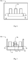
- Fig. 1 is a perspective view of a transformer core 1a according to an embodiment.
- the vertical portions (around which windings are wound) of the transformer core 1a are commonly referred to as limbs or legs 3a, 3b and the top and bottom portions of the transformer core 1a are commonly referred to as yokes 2a, 2b.
- the yokes 2a, 2b are made from amorphous steel whereas the limbs 3a, 3b are made from grain-oriented core steel.
- the magnetic core is composed of a stack of thin silicon-steel lamination.
- the laminates are typically in the order of about 0.17 -0.35 mm thick.
- the disclosed embodiments relate to transformer cores, especially such transformer cores which combine parts of amorphous steel with parts of grain-oriented steel.
- the transformer core 1a of Fig. 1 will now be described in more detail.
- the transformer core 1a comprises a first yoke 2a and a second yoke 2b.
- the first yoke 2a is of grain-oriented steel.
- the second yoke 2b is either of grain-oriented steel or of amorphous steel.
- the transformer core 1a comprises at least two limbs 3a, 3b.
- the at least two limbs 3a, 3b extend between the first yoke 2a and the second yoke 2b. That is, the limbs 3a, 3b are coupled to the yokes 2a, 2b. Particularly, a first end 4a, 4b of each one of the limbs 3a, 3b is coupled to a first surface 5a of the first yoke 2a. A second end 6a, 6b of each one of the limbs 3a, 3b is coupled to a second surface 5b of the second yoke 2b.
- the limbs 3a, 3b are either of grain-oriented steel or amorphous steel.
- At least one of the second yoke 2b and one of the at least two limbs 3a, 3b is of amorphous steel.
- the transformer core 1a may thus be regarded as a semi-hybrid core.
- the first yoke 2a is of is of grain-oriented steel. According to an embodiment the first yoke 2a is composed of a plurality of stacked limb plates of grain-oriented steel.
- the first yoke 2a is a top yoke (and hence the second yoke 2b is a bottom yoke). That is, during operation of the transformer core 1a, the transformer core 1a oriented such that the first yoke 2a is positioned vertically higher than the second yoke 2b.
- the second yoke 2b is of amorphous steel.
- the second yoke 2b is then composed of at least one yoke beam, each yoke beam comprising a plurality of stacked yoke plates 8 of amorphous steel, as illustrated in Fig. 4 .
- each yoke beam comprising a plurality of stacked yoke plates 8 of amorphous steel, as illustrated in Fig. 4 .
- the thickness of the yoke plates 8 used in the design, in the order of 5 to 10 yoke plates 8 (each defined by an amorphous tape) could be used to approximately match the thickness of the lamination thickness of the grain oriented steel.
- the stacked plurality of yoke plates 8 may be glued together.
- the second yoke 2b may therefore be regarded as a glued package where the mechanical strength is obtained by the glue. According to an embodiment the second yoke is dimensioned according to its saturation flux limit. Alternatively, the second yoke 2b is of grain oriented steel. The the second yoke 2b could then be composed of a plurality of stacked limb plates of grain-oriented steel.
- the limbs 3a, 3b could be of amorphous steel or grain-oriented steel; at least one of the limbs 3a, 3b could be of amorphous steel and at least one other of the limbs 3a, 3b could be of grain-oriented steel. That is, according to an embodiment, those of the at least two limbs that are not of amorphous steel are of grain-oriented steel. However, alternatively, all limbs 3a, 3b are of grain-oriented steel.
- limbs 3a, 3b may vary. Further, some of the limbs may be wound and some of the limbs may be unwound.
- Fig. 2 illustrates a transformer core 1b where the two limbs 3a, 3b each have a winding 11a, 11b, thus forming wound limbs 3a, 3b. In general terms, the transformer core 1b could have at least two wound limbs 3a, 3b.
- Fig. 3 illustrates a transformer core 1c comprising three limbs 3a, 3c, 3d. The limb 3a is placed between the limbs 3c, 3d. The limbs 3c, 3d may therefore be regarded as side limbs.
- the limb 3a has a winding 11a, thus forming a wound limb 3a.
- the limbs 3c, 3d do not have any windings, thus forming unwound limbs 3c, 3d.
- the transformer core 1c could have at least one wound limb 3a provided between the two unwound limbs 3c, 3d.
- limbs 3a, 3b, 3c, 3d there could be different ways to select which of the limbs 3a, 3b, 3c, 3d to be of amorphous steel and which of the limbs 3a, 3b, 3c, 3d to be of grain-oriented steel.
- Whether a limb is to be of amorphous steel or grain-oriented steel could depend on whether the limb is wound or unwound.
- the wound limbs 3a, 3b could be of grain-oriented steel.
- all limbs 3a, 3b that are wound are of grain-oriented steel.
- the unwound limbs 3c, 3d could be of amorphous steel.
- all limbs 3c, 3d that are unwound are of amorphous steel.
- the side limbs 3c, 3d could be of amorphous steel.
- the side limbs 3c, 3d are of amorphous steel.
- the side limbs 3c, 3d are of amorphous steel.
- other combinations of use of amorphous steel and grain-oriented steel of the limbs 3a, 3b, 3c, 3d are possible.
- each limb 3a, 3b of grain-oriented steel could be composed of a stacked plurality of limb plates 10 of grain-oriented steel.
- Fig 5 illustrates a limb 3a, 3b having a plurality of limb plates 10.
- the plurality of limb plates 10 are preferably glued or bonded.
- each winding 11a, 11b should be interpreted as representing at least one winding.
- all limbs 3a, 3b, 3c, 3d are attached to at least one of the yokes 2a, 2b using a step-lap joint.
- a step wise shift of the joints it is possible to reduce the magnetization losses in the joints between the limbs 3a, 3b, 3c, 3d and the yokes 2a, 2b, due to minimization cross flow of fluxes.
- Examples of attaching limbs 3a, 3b, 3c, 3d to yokes 2a, 2b using a step-lap joint are provided in US 4200854 A and in S.V. Kulkarni, S.A.
- Step-lap joints could be designed to have one lamination of grain-oriented steel against a single bunch of tapes of amorphous steel or it could have multiple one laminations of grain-oriented steel against multiple bunches of tapes of amorphous steel.
- all limbs 3a, 3b, 3c, 3d are attached to at least one of the yokes 2a, 2b using a butt-lap joint.
- attaching limbs 3a, 3b, 3c, 3d to yokes 2a, 2b using a butt-lap joint is provided in S.V. Kulkarni, S.A. Khaparde, "Transformer engineering: design and practice", CRC Press, 2004.Chapter 2, page 39-41 .
- all limbs 3a, 3b, 3c, 3d are attached to both the yokes 2a, 2b using a step-lap joint, or that all limbs 3a, 3b, 3c, 3d are attached to both the yokes 2a, 2b using a butt-lap joint.
- all limbs 3a, 3b, 3c, 3d are attached to one of the yokes 2a, 2b using a step-lap joint and to the other of the yokes 2a, 2b using a butt-lap joint.
- step-lap joints could be superior to butt-lap joints in terms of performance loss. However, this difference is smaller for joints between grain-oriented steel and amorphous steel and for joints between amorphous steel and amorphous steel compared to joints between grain-oriented steel and grain-oriented steel.
- FIG. 9 A method for manufacturing a transformer core 1a, 1b, 1c according to any of the embodiments disclosed above will now be disclosed with reference to the flowchart of Fig. 9 .
- Parallel references are also made to Figs. 6, 7 , and 8 which illustrate a schematic assembly sequence of the transformer core 1a, 1b, 1c.
- the method comprises placing (step S102) the second yoke 2b and attaching the at least two limbs 3a, 3b, 3c, 3d to the second yoke 2b in horizontal orientation to form an initial arrangement 12a.
- Fig. 6 illustrates a (bottom) second yoke 2b made of amorphous steel being provided on a horizontal surface, such as on a table top 13.
- the second yoke 2b yoke is stacked together with three limbs 3a, 3b, 3c of grain-oriented steel on the horizontal surface to form the initial arrangement 12a.
- the method comprises raising (step S104) the initial arrangement 12a to vertical orientation and placing windings 11a, 11b on at least one of the at least two limbs 3a, 3b, 3c, 3d to form an intermediate arrangement 12b (i.e., windings 11a, 11b are placed on all limbs 3a, 3b, 3c, 3d that are to be wound).
- Fig. 7 illustrates the initial arrangement 12a of Fig. 6 after having been raised (as indicated by arrow 14) to have a vertical orientation.
- the initial arrangement 12a could be raised by means of a core holding arrangement 15. Then windings 11a are assembled on limb 3a to form the intermediate arrangement 12b.
- the method comprises attaching (step S106) the first yoke 2a to the at least two limbs 3a, 3b, 3c, 3d.
- Fig. 8 illustrates intermediate arrangement 12b of Fig. 7 when being provided (as indicated by arrow 16) with a (top) first yoke 2a to form a complete arrangement 12c.
- the complete arrangement 12c is then removed from the core holding arrangement 15.
- the illustrated complete arrangement 12c thus corresponds to the transformer core 1c of Fig. 3 .
- the herein disclosed transformer cores may be provided in a reactor. There is thus provided a reactor comprising at least one transformer core as herein disclosed.
- transformer cores according to embodiments as schematically illustrated in Figs. 1-8 could equally well be a reactor core.
- reactors in general terms, with regard to reactors (inductors), these comprise a core which mostly is provided with only one winding. In other respects, what has been stated above concerning transformers is substantially relevant also to reactors.
- the reactor may be a shunt reactor or a series reactor.
- the herein disclosed transformer core may according to one embodiment be applied in reactors with air as limbs without electrical core steel. Such reactors are preferably suitable for a reactive power in the region of kVAR (volt-ampere reactive) to a few MVAR.
- the herein disclosed transformer core may according to another embodiment be applied in reactors limbs with air gaps with (electrical) core steel. Such reactors are preferably suitable for a reactive power in the region of several MVAR.
- the invention has mainly been described above with reference to a few embodiments. However, as is readily appreciated by a person skilled in the art, other embodiments than the ones disclosed above are equally possible within the scope of the invention, as defined by the appended patent claims. For example, generally, since the amorphous yokes can be built up of parallel widths of existing amorphous bands, the disclosed transformer core is not limited to any maximum size.
Priority Applications (8)
| Application Number | Priority Date | Filing Date | Title |
|---|---|---|---|
| EP16201865.9A EP3330980B1 (fr) | 2016-12-02 | 2016-12-02 | Noyau de transformateur semi-hybride |
| HUE16201865A HUE045135T2 (hu) | 2016-12-02 | 2016-12-02 | Félhibrid transzformátormag |
| PL16201865T PL3330980T3 (pl) | 2016-12-02 | 2016-12-02 | Półhybrydowy rdzeń transformatora |
| CA3045709A CA3045709C (fr) | 2016-12-02 | 2017-11-17 | Noyau de transformateur semi-hybride |
| JP2019529586A JP2020501365A (ja) | 2016-12-02 | 2017-11-17 | 半ハイブリッド変圧器コア |
| US16/466,079 US20200185140A1 (en) | 2016-12-02 | 2017-11-17 | Semi-Hybrid Transformer Core |
| PCT/EP2017/079631 WO2018099737A1 (fr) | 2016-12-02 | 2017-11-17 | Noyau de transformateur semi-hybride |
| CN201780074545.9A CN110121752B (zh) | 2016-12-02 | 2017-11-17 | 半混合变压器芯 |
Applications Claiming Priority (1)
| Application Number | Priority Date | Filing Date | Title |
|---|---|---|---|
| EP16201865.9A EP3330980B1 (fr) | 2016-12-02 | 2016-12-02 | Noyau de transformateur semi-hybride |
Publications (2)
| Publication Number | Publication Date |
|---|---|
| EP3330980A1 true EP3330980A1 (fr) | 2018-06-06 |
| EP3330980B1 EP3330980B1 (fr) | 2019-07-31 |
Family
ID=57471716
Family Applications (1)
| Application Number | Title | Priority Date | Filing Date |
|---|---|---|---|
| EP16201865.9A Active EP3330980B1 (fr) | 2016-12-02 | 2016-12-02 | Noyau de transformateur semi-hybride |
Country Status (8)
| Country | Link |
|---|---|
| US (1) | US20200185140A1 (fr) |
| EP (1) | EP3330980B1 (fr) |
| JP (1) | JP2020501365A (fr) |
| CN (1) | CN110121752B (fr) |
| CA (1) | CA3045709C (fr) |
| HU (1) | HUE045135T2 (fr) |
| PL (1) | PL3330980T3 (fr) |
| WO (1) | WO2018099737A1 (fr) |
Cited By (2)
| Publication number | Priority date | Publication date | Assignee | Title |
|---|---|---|---|---|
| JP2021002585A (ja) * | 2019-06-21 | 2021-01-07 | パナソニックIpマネジメント株式会社 | コア |
| EP3841598A4 (fr) * | 2018-08-20 | 2022-05-18 | Fogelberg Consulting AB | Coeurs de transformateurs et de réacteurs présentant de nouvelles conceptions, et procédés de fabrication |
Citations (4)
| Publication number | Priority date | Publication date | Assignee | Title |
|---|---|---|---|---|
| US4200854A (en) | 1979-01-04 | 1980-04-29 | Westinghouse Electric Corp. | Core with step-lap joints |
| US4668931A (en) * | 1986-02-18 | 1987-05-26 | General Electric Company | Composite silicon steel-amorphous steel transformer core |
| JP2009117442A (ja) * | 2007-11-02 | 2009-05-28 | Jfe Steel Corp | 複合リアクトル |
| EP2685477A1 (fr) * | 2012-07-13 | 2014-01-15 | ABB Technology Ltd | Noyaux de transformateur hybride |
Family Cites Families (14)
| Publication number | Priority date | Publication date | Assignee | Title |
|---|---|---|---|---|
| JPS5044615U (fr) * | 1973-08-27 | 1975-05-06 | ||
| JPS57126113A (en) * | 1981-01-27 | 1982-08-05 | Matsushita Electric Ind Co Ltd | Magnetic core |
| JPS5856422U (ja) * | 1981-10-13 | 1983-04-16 | 三菱電機株式会社 | 変圧器 |
| JPS59130409A (ja) * | 1983-01-17 | 1984-07-27 | Toshiba Corp | 積層鉄心 |
| US4520335A (en) * | 1983-04-06 | 1985-05-28 | Westinghouse Electric Corp. | Transformer with ferromagnetic circuits of unequal saturation inductions |
| JPS6226013U (fr) * | 1985-07-30 | 1987-02-17 | ||
| US6668444B2 (en) * | 2001-04-25 | 2003-12-30 | Metglas, Inc. | Method for manufacturing a wound, multi-cored amorphous metal transformer core |
| JP5686439B2 (ja) * | 2011-08-29 | 2015-03-18 | 株式会社日立製作所 | 静止誘導電器用積層鉄心 |
| JP5856422B2 (ja) * | 2011-09-30 | 2016-02-09 | 理研ビタミン株式会社 | 酸性飲食品用呈味改善剤 |
| CN104715899A (zh) * | 2013-12-12 | 2015-06-17 | 台达电子企业管理(上海)有限公司 | 三相电抗器 |
| JP3189478U (ja) * | 2013-12-27 | 2014-03-13 | 関口電気株式会社 | 積鉄心の組立構造 |
| CN104779037B (zh) * | 2014-01-09 | 2018-01-30 | 台达电子企业管理(上海)有限公司 | 电抗器 |
| US9570225B2 (en) * | 2014-03-27 | 2017-02-14 | Chieh-Sen Tu | Magnetoelectric device capable of storing usable electrical energy |
| CN104021920B (zh) * | 2014-05-27 | 2016-09-28 | 华为技术有限公司 | 耦合电感和功率变换器 |
-
2016
- 2016-12-02 PL PL16201865T patent/PL3330980T3/pl unknown
- 2016-12-02 EP EP16201865.9A patent/EP3330980B1/fr active Active
- 2016-12-02 HU HUE16201865A patent/HUE045135T2/hu unknown
-
2017
- 2017-11-17 WO PCT/EP2017/079631 patent/WO2018099737A1/fr active Application Filing
- 2017-11-17 US US16/466,079 patent/US20200185140A1/en not_active Abandoned
- 2017-11-17 CN CN201780074545.9A patent/CN110121752B/zh not_active Expired - Fee Related
- 2017-11-17 CA CA3045709A patent/CA3045709C/fr not_active Expired - Fee Related
- 2017-11-17 JP JP2019529586A patent/JP2020501365A/ja active Pending
Patent Citations (4)
| Publication number | Priority date | Publication date | Assignee | Title |
|---|---|---|---|---|
| US4200854A (en) | 1979-01-04 | 1980-04-29 | Westinghouse Electric Corp. | Core with step-lap joints |
| US4668931A (en) * | 1986-02-18 | 1987-05-26 | General Electric Company | Composite silicon steel-amorphous steel transformer core |
| JP2009117442A (ja) * | 2007-11-02 | 2009-05-28 | Jfe Steel Corp | 複合リアクトル |
| EP2685477A1 (fr) * | 2012-07-13 | 2014-01-15 | ABB Technology Ltd | Noyaux de transformateur hybride |
Non-Patent Citations (1)
| Title |
|---|
| S.V. KULKARNI; S.A. KHAPARDE: "Transformer engineering: design and practice", 2004, CRC PRESS, pages: 39 - 41 |
Cited By (3)
| Publication number | Priority date | Publication date | Assignee | Title |
|---|---|---|---|---|
| EP3841598A4 (fr) * | 2018-08-20 | 2022-05-18 | Fogelberg Consulting AB | Coeurs de transformateurs et de réacteurs présentant de nouvelles conceptions, et procédés de fabrication |
| JP2021002585A (ja) * | 2019-06-21 | 2021-01-07 | パナソニックIpマネジメント株式会社 | コア |
| US11798724B2 (en) | 2019-06-21 | 2023-10-24 | Panasonic Intellectual Property Management Co., Ltd. | Core |
Also Published As
| Publication number | Publication date |
|---|---|
| HUE045135T2 (hu) | 2019-12-30 |
| US20200185140A1 (en) | 2020-06-11 |
| CN110121752B (zh) | 2021-06-18 |
| PL3330980T3 (pl) | 2020-03-31 |
| CN110121752A (zh) | 2019-08-13 |
| CA3045709C (fr) | 2020-01-14 |
| CA3045709A1 (fr) | 2018-06-07 |
| WO2018099737A1 (fr) | 2018-06-07 |
| EP3330980B1 (fr) | 2019-07-31 |
| JP2020501365A (ja) | 2020-01-16 |
Similar Documents
| Publication | Publication Date | Title |
|---|---|---|
| EP2873078B1 (fr) | Noyaux de transformateur hybride | |
| CN103559977B (zh) | 功率转换器的磁性装置 | |
| EP2677526B1 (fr) | Éléments magnétiques intégrés pour convertisseur de puissance à découpage | |
| WO2013065095A1 (fr) | Réacteur, transformateur et appareil de conversion d'énergie les utilisant | |
| US7253714B1 (en) | Power supply transformer with high efficiency | |
| EP2590187A2 (fr) | Transformateur à noyau amorphe | |
| US9412510B2 (en) | Three-phase reactor | |
| MX2014005762A (es) | Metodo de elaboracion de nucleo enrollado para configuraciones de nucleo partido. | |
| CN105632712B (zh) | 一种高频高压大功率整流变压器 | |
| CA3045709C (fr) | Noyau de transformateur semi-hybride | |
| KR101505873B1 (ko) | 분리형 전력용 전자기 유도 장치의 제조 방법 | |
| US20120243268A1 (en) | Transformers and Methods For Constructing Transformers | |
| JP2013254827A (ja) | 変圧器 | |
| KR102136026B1 (ko) | 자속 보조용 페라이트 코어를 이용한 용량 가변형 변압기 구조체 결합구조 및 그 제조 방법 | |
| US20150279544A1 (en) | Transformer Having An Interlocking Core Frame | |
| US10186370B1 (en) | Transformers with integrated inductors | |
| US7750526B2 (en) | Circulatory current choke | |
| CN203799837U (zh) | 一种非晶合金变压器 | |
| JP2020145213A (ja) | 静止誘導電器用鉄心 | |
| CN103824688B (zh) | 三相变单相滤波变压器 | |
| EP3282457A1 (fr) | Câble haute tension pour un enroulement et dispositif à induction électromagnétique comprenant celui-ci | |
| KR101525216B1 (ko) | 하이브리드 리액터 | |
| KR102131584B1 (ko) | 변압기 코어부의 모서리 포화 저감 구조체 및 그 제조 방법 | |
| JP2023527437A (ja) | ハイブリッド変圧器コアおよび変圧器コアを製造する方法 | |
| CN110415943A (zh) | 变压器和对电压进行降压的方法 |
Legal Events
| Date | Code | Title | Description |
|---|---|---|---|
| PUAI | Public reference made under article 153(3) epc to a published international application that has entered the european phase |
Free format text: ORIGINAL CODE: 0009012 |
|
| STAA | Information on the status of an ep patent application or granted ep patent |
Free format text: STATUS: THE APPLICATION HAS BEEN PUBLISHED |
|
| AK | Designated contracting states |
Kind code of ref document: A1 Designated state(s): AL AT BE BG CH CY CZ DE DK EE ES FI FR GB GR HR HU IE IS IT LI LT LU LV MC MK MT NL NO PL PT RO RS SE SI SK SM TR |
|
| AX | Request for extension of the european patent |
Extension state: BA ME |
|
| STAA | Information on the status of an ep patent application or granted ep patent |
Free format text: STATUS: REQUEST FOR EXAMINATION WAS MADE |
|
| 17P | Request for examination filed |
Effective date: 20181206 |
|
| RBV | Designated contracting states (corrected) |
Designated state(s): AL AT BE BG CH CY CZ DE DK EE ES FI FR GB GR HR HU IE IS IT LI LT LU LV MC MK MT NL NO PL PT RO RS SE SI SK SM TR |
|
| GRAP | Despatch of communication of intention to grant a patent |
Free format text: ORIGINAL CODE: EPIDOSNIGR1 |
|
| STAA | Information on the status of an ep patent application or granted ep patent |
Free format text: STATUS: GRANT OF PATENT IS INTENDED |
|
| INTG | Intention to grant announced |
Effective date: 20190321 |
|
| GRAS | Grant fee paid |
Free format text: ORIGINAL CODE: EPIDOSNIGR3 |
|
| GRAA | (expected) grant |
Free format text: ORIGINAL CODE: 0009210 |
|
| STAA | Information on the status of an ep patent application or granted ep patent |
Free format text: STATUS: THE PATENT HAS BEEN GRANTED |
|
| AK | Designated contracting states |
Kind code of ref document: B1 Designated state(s): AL AT BE BG CH CY CZ DE DK EE ES FI FR GB GR HR HU IE IS IT LI LT LU LV MC MK MT NL NO PL PT RO RS SE SI SK SM TR |
|
| REG | Reference to a national code |
Ref country code: CH Ref legal event code: EP Ref country code: GB Ref legal event code: FG4D |
|
| REG | Reference to a national code |
Ref country code: AT Ref legal event code: REF Ref document number: 1161791 Country of ref document: AT Kind code of ref document: T Effective date: 20190815 |
|
| REG | Reference to a national code |
Ref country code: IE Ref legal event code: FG4D |
|
| REG | Reference to a national code |
Ref country code: DE Ref legal event code: R096 Ref document number: 602016017648 Country of ref document: DE |
|
| REG | Reference to a national code |
Ref country code: NL Ref legal event code: MP Effective date: 20190731 |
|
| REG | Reference to a national code |
Ref country code: LT Ref legal event code: MG4D |
|
| REG | Reference to a national code |
Ref country code: HU Ref legal event code: AG4A Ref document number: E045135 Country of ref document: HU |
|
| REG | Reference to a national code |
Ref country code: AT Ref legal event code: MK05 Ref document number: 1161791 Country of ref document: AT Kind code of ref document: T Effective date: 20190731 |
|
| PG25 | Lapsed in a contracting state [announced via postgrant information from national office to epo] |
Ref country code: PT Free format text: LAPSE BECAUSE OF FAILURE TO SUBMIT A TRANSLATION OF THE DESCRIPTION OR TO PAY THE FEE WITHIN THE PRESCRIBED TIME-LIMIT Effective date: 20191202 Ref country code: NO Free format text: LAPSE BECAUSE OF FAILURE TO SUBMIT A TRANSLATION OF THE DESCRIPTION OR TO PAY THE FEE WITHIN THE PRESCRIBED TIME-LIMIT Effective date: 20191031 Ref country code: NL Free format text: LAPSE BECAUSE OF FAILURE TO SUBMIT A TRANSLATION OF THE DESCRIPTION OR TO PAY THE FEE WITHIN THE PRESCRIBED TIME-LIMIT Effective date: 20190731 Ref country code: BG Free format text: LAPSE BECAUSE OF FAILURE TO SUBMIT A TRANSLATION OF THE DESCRIPTION OR TO PAY THE FEE WITHIN THE PRESCRIBED TIME-LIMIT Effective date: 20191031 Ref country code: HR Free format text: LAPSE BECAUSE OF FAILURE TO SUBMIT A TRANSLATION OF THE DESCRIPTION OR TO PAY THE FEE WITHIN THE PRESCRIBED TIME-LIMIT Effective date: 20190731 Ref country code: LT Free format text: LAPSE BECAUSE OF FAILURE TO SUBMIT A TRANSLATION OF THE DESCRIPTION OR TO PAY THE FEE WITHIN THE PRESCRIBED TIME-LIMIT Effective date: 20190731 Ref country code: AT Free format text: LAPSE BECAUSE OF FAILURE TO SUBMIT A TRANSLATION OF THE DESCRIPTION OR TO PAY THE FEE WITHIN THE PRESCRIBED TIME-LIMIT Effective date: 20190731 Ref country code: FI Free format text: LAPSE BECAUSE OF FAILURE TO SUBMIT A TRANSLATION OF THE DESCRIPTION OR TO PAY THE FEE WITHIN THE PRESCRIBED TIME-LIMIT Effective date: 20190731 Ref country code: SE Free format text: LAPSE BECAUSE OF FAILURE TO SUBMIT A TRANSLATION OF THE DESCRIPTION OR TO PAY THE FEE WITHIN THE PRESCRIBED TIME-LIMIT Effective date: 20190731 |
|
| PG25 | Lapsed in a contracting state [announced via postgrant information from national office to epo] |
Ref country code: AL Free format text: LAPSE BECAUSE OF FAILURE TO SUBMIT A TRANSLATION OF THE DESCRIPTION OR TO PAY THE FEE WITHIN THE PRESCRIBED TIME-LIMIT Effective date: 20190731 Ref country code: RS Free format text: LAPSE BECAUSE OF FAILURE TO SUBMIT A TRANSLATION OF THE DESCRIPTION OR TO PAY THE FEE WITHIN THE PRESCRIBED TIME-LIMIT Effective date: 20190731 Ref country code: IS Free format text: LAPSE BECAUSE OF FAILURE TO SUBMIT A TRANSLATION OF THE DESCRIPTION OR TO PAY THE FEE WITHIN THE PRESCRIBED TIME-LIMIT Effective date: 20191130 Ref country code: ES Free format text: LAPSE BECAUSE OF FAILURE TO SUBMIT A TRANSLATION OF THE DESCRIPTION OR TO PAY THE FEE WITHIN THE PRESCRIBED TIME-LIMIT Effective date: 20190731 Ref country code: LV Free format text: LAPSE BECAUSE OF FAILURE TO SUBMIT A TRANSLATION OF THE DESCRIPTION OR TO PAY THE FEE WITHIN THE PRESCRIBED TIME-LIMIT Effective date: 20190731 Ref country code: GR Free format text: LAPSE BECAUSE OF FAILURE TO SUBMIT A TRANSLATION OF THE DESCRIPTION OR TO PAY THE FEE WITHIN THE PRESCRIBED TIME-LIMIT Effective date: 20191101 |
|
| PG25 | Lapsed in a contracting state [announced via postgrant information from national office to epo] |
Ref country code: RO Free format text: LAPSE BECAUSE OF FAILURE TO SUBMIT A TRANSLATION OF THE DESCRIPTION OR TO PAY THE FEE WITHIN THE PRESCRIBED TIME-LIMIT Effective date: 20190731 Ref country code: EE Free format text: LAPSE BECAUSE OF FAILURE TO SUBMIT A TRANSLATION OF THE DESCRIPTION OR TO PAY THE FEE WITHIN THE PRESCRIBED TIME-LIMIT Effective date: 20190731 Ref country code: DK Free format text: LAPSE BECAUSE OF FAILURE TO SUBMIT A TRANSLATION OF THE DESCRIPTION OR TO PAY THE FEE WITHIN THE PRESCRIBED TIME-LIMIT Effective date: 20190731 |
|
| PG25 | Lapsed in a contracting state [announced via postgrant information from national office to epo] |
Ref country code: CZ Free format text: LAPSE BECAUSE OF FAILURE TO SUBMIT A TRANSLATION OF THE DESCRIPTION OR TO PAY THE FEE WITHIN THE PRESCRIBED TIME-LIMIT Effective date: 20190731 Ref country code: SK Free format text: LAPSE BECAUSE OF FAILURE TO SUBMIT A TRANSLATION OF THE DESCRIPTION OR TO PAY THE FEE WITHIN THE PRESCRIBED TIME-LIMIT Effective date: 20190731 Ref country code: IS Free format text: LAPSE BECAUSE OF FAILURE TO SUBMIT A TRANSLATION OF THE DESCRIPTION OR TO PAY THE FEE WITHIN THE PRESCRIBED TIME-LIMIT Effective date: 20200224 Ref country code: SM Free format text: LAPSE BECAUSE OF FAILURE TO SUBMIT A TRANSLATION OF THE DESCRIPTION OR TO PAY THE FEE WITHIN THE PRESCRIBED TIME-LIMIT Effective date: 20190731 |
|
| REG | Reference to a national code |
Ref country code: DE Ref legal event code: R097 Ref document number: 602016017648 Country of ref document: DE |
|
| PLBE | No opposition filed within time limit |
Free format text: ORIGINAL CODE: 0009261 |
|
| STAA | Information on the status of an ep patent application or granted ep patent |
Free format text: STATUS: NO OPPOSITION FILED WITHIN TIME LIMIT |
|
| PG2D | Information on lapse in contracting state deleted |
Ref country code: IS |
|
| PG25 | Lapsed in a contracting state [announced via postgrant information from national office to epo] |
Ref country code: IS Free format text: LAPSE BECAUSE OF FAILURE TO SUBMIT A TRANSLATION OF THE DESCRIPTION OR TO PAY THE FEE WITHIN THE PRESCRIBED TIME-LIMIT Effective date: 20191030 |
|
| REG | Reference to a national code |
Ref country code: CH Ref legal event code: PL |
|
| 26N | No opposition filed |
Effective date: 20200603 |
|
| REG | Reference to a national code |
Ref country code: BE Ref legal event code: MM Effective date: 20191231 |
|
| PG25 | Lapsed in a contracting state [announced via postgrant information from national office to epo] |
Ref country code: SI Free format text: LAPSE BECAUSE OF FAILURE TO SUBMIT A TRANSLATION OF THE DESCRIPTION OR TO PAY THE FEE WITHIN THE PRESCRIBED TIME-LIMIT Effective date: 20190731 Ref country code: MC Free format text: LAPSE BECAUSE OF FAILURE TO SUBMIT A TRANSLATION OF THE DESCRIPTION OR TO PAY THE FEE WITHIN THE PRESCRIBED TIME-LIMIT Effective date: 20190731 |
|
| PG25 | Lapsed in a contracting state [announced via postgrant information from national office to epo] |
Ref country code: IE Free format text: LAPSE BECAUSE OF NON-PAYMENT OF DUE FEES Effective date: 20191202 Ref country code: LU Free format text: LAPSE BECAUSE OF NON-PAYMENT OF DUE FEES Effective date: 20191202 |
|
| PG25 | Lapsed in a contracting state [announced via postgrant information from national office to epo] |
Ref country code: BE Free format text: LAPSE BECAUSE OF NON-PAYMENT OF DUE FEES Effective date: 20191231 Ref country code: CH Free format text: LAPSE BECAUSE OF NON-PAYMENT OF DUE FEES Effective date: 20191231 Ref country code: LI Free format text: LAPSE BECAUSE OF NON-PAYMENT OF DUE FEES Effective date: 20191231 |
|
| PGFP | Annual fee paid to national office [announced via postgrant information from national office to epo] |
Ref country code: TR Payment date: 20201127 Year of fee payment: 5 |
|
| PGFP | Annual fee paid to national office [announced via postgrant information from national office to epo] |
Ref country code: FR Payment date: 20201223 Year of fee payment: 5 Ref country code: GB Payment date: 20201223 Year of fee payment: 5 Ref country code: DE Payment date: 20201211 Year of fee payment: 5 |
|
| PGFP | Annual fee paid to national office [announced via postgrant information from national office to epo] |
Ref country code: PL Payment date: 20201124 Year of fee payment: 5 |
|
| PGFP | Annual fee paid to national office [announced via postgrant information from national office to epo] |
Ref country code: IT Payment date: 20201224 Year of fee payment: 5 |
|
| REG | Reference to a national code |
Ref country code: DE Ref legal event code: R081 Ref document number: 602016017648 Country of ref document: DE Owner name: ABB POWER GRIDS SWITZERLAND AG, CH Free format text: FORMER OWNER: ABB SCHWEIZ AG, BADEN, CH |
|
| PG25 | Lapsed in a contracting state [announced via postgrant information from national office to epo] |
Ref country code: CY Free format text: LAPSE BECAUSE OF FAILURE TO SUBMIT A TRANSLATION OF THE DESCRIPTION OR TO PAY THE FEE WITHIN THE PRESCRIBED TIME-LIMIT Effective date: 20190731 |
|
| PGFP | Annual fee paid to national office [announced via postgrant information from national office to epo] |
Ref country code: HU Payment date: 20210131 Year of fee payment: 5 |
|
| PG25 | Lapsed in a contracting state [announced via postgrant information from national office to epo] |
Ref country code: MT Free format text: LAPSE BECAUSE OF FAILURE TO SUBMIT A TRANSLATION OF THE DESCRIPTION OR TO PAY THE FEE WITHIN THE PRESCRIBED TIME-LIMIT Effective date: 20190731 |
|
| REG | Reference to a national code |
Ref country code: GB Ref legal event code: 732E Free format text: REGISTERED BETWEEN 20211104 AND 20211110 |
|
| PG25 | Lapsed in a contracting state [announced via postgrant information from national office to epo] |
Ref country code: MK Free format text: LAPSE BECAUSE OF FAILURE TO SUBMIT A TRANSLATION OF THE DESCRIPTION OR TO PAY THE FEE WITHIN THE PRESCRIBED TIME-LIMIT Effective date: 20190731 |
|
| REG | Reference to a national code |
Ref country code: DE Ref legal event code: R119 Ref document number: 602016017648 Country of ref document: DE |
|
| GBPC | Gb: european patent ceased through non-payment of renewal fee |
Effective date: 20211202 |
|
| PG25 | Lapsed in a contracting state [announced via postgrant information from national office to epo] |
Ref country code: GB Free format text: LAPSE BECAUSE OF NON-PAYMENT OF DUE FEES Effective date: 20211202 Ref country code: DE Free format text: LAPSE BECAUSE OF NON-PAYMENT OF DUE FEES Effective date: 20220701 |
|
| PG25 | Lapsed in a contracting state [announced via postgrant information from national office to epo] |
Ref country code: HU Free format text: LAPSE BECAUSE OF NON-PAYMENT OF DUE FEES Effective date: 20211203 Ref country code: FR Free format text: LAPSE BECAUSE OF NON-PAYMENT OF DUE FEES Effective date: 20211231 |
|
| PG25 | Lapsed in a contracting state [announced via postgrant information from national office to epo] |
Ref country code: IT Free format text: LAPSE BECAUSE OF NON-PAYMENT OF DUE FEES Effective date: 20211202 |
|
| PG25 | Lapsed in a contracting state [announced via postgrant information from national office to epo] |
Ref country code: PL Free format text: LAPSE BECAUSE OF NON-PAYMENT OF DUE FEES Effective date: 20211202 |