EP3330769A1 - Head-up display device - Google Patents
Head-up display device Download PDFInfo
- Publication number
- EP3330769A1 EP3330769A1 EP16830303.0A EP16830303A EP3330769A1 EP 3330769 A1 EP3330769 A1 EP 3330769A1 EP 16830303 A EP16830303 A EP 16830303A EP 3330769 A1 EP3330769 A1 EP 3330769A1
- Authority
- EP
- European Patent Office
- Prior art keywords
- light
- screen
- reflecting
- head
- display device
- Prior art date
- Legal status (The legal status is an assumption and is not a legal conclusion. Google has not performed a legal analysis and makes no representation as to the accuracy of the status listed.)
- Granted
Links
- 230000003287 optical effect Effects 0.000 claims abstract description 48
- 239000011521 glass Substances 0.000 description 25
- 239000000463 material Substances 0.000 description 9
- 238000000034 method Methods 0.000 description 5
- 229920003002 synthetic resin Polymers 0.000 description 5
- 239000000057 synthetic resin Substances 0.000 description 5
- 239000010408 film Substances 0.000 description 4
- 238000005286 illumination Methods 0.000 description 4
- 238000007740 vapor deposition Methods 0.000 description 4
- 230000000694 effects Effects 0.000 description 3
- 239000004973 liquid crystal related substance Substances 0.000 description 2
- 238000010276 construction Methods 0.000 description 1
- 238000009792 diffusion process Methods 0.000 description 1
- 229920005989 resin Polymers 0.000 description 1
- 239000011347 resin Substances 0.000 description 1
- 229910052710 silicon Inorganic materials 0.000 description 1
- 239000010703 silicon Substances 0.000 description 1
- 239000010409 thin film Substances 0.000 description 1
- 230000003245 working effect Effects 0.000 description 1
Images


Classifications
-
- G—PHYSICS
- G02—OPTICS
- G02B—OPTICAL ELEMENTS, SYSTEMS OR APPARATUS
- G02B27/00—Optical systems or apparatus not provided for by any of the groups G02B1/00 - G02B26/00, G02B30/00
- G02B27/01—Head-up displays
- G02B27/0101—Head-up displays characterised by optical features
-
- B—PERFORMING OPERATIONS; TRANSPORTING
- B60—VEHICLES IN GENERAL
- B60K—ARRANGEMENT OR MOUNTING OF PROPULSION UNITS OR OF TRANSMISSIONS IN VEHICLES; ARRANGEMENT OR MOUNTING OF PLURAL DIVERSE PRIME-MOVERS IN VEHICLES; AUXILIARY DRIVES FOR VEHICLES; INSTRUMENTATION OR DASHBOARDS FOR VEHICLES; ARRANGEMENTS IN CONNECTION WITH COOLING, AIR INTAKE, GAS EXHAUST OR FUEL SUPPLY OF PROPULSION UNITS IN VEHICLES
- B60K35/00—Instruments specially adapted for vehicles; Arrangement of instruments in or on vehicles
-
- B—PERFORMING OPERATIONS; TRANSPORTING
- B60—VEHICLES IN GENERAL
- B60K—ARRANGEMENT OR MOUNTING OF PROPULSION UNITS OR OF TRANSMISSIONS IN VEHICLES; ARRANGEMENT OR MOUNTING OF PLURAL DIVERSE PRIME-MOVERS IN VEHICLES; AUXILIARY DRIVES FOR VEHICLES; INSTRUMENTATION OR DASHBOARDS FOR VEHICLES; ARRANGEMENTS IN CONNECTION WITH COOLING, AIR INTAKE, GAS EXHAUST OR FUEL SUPPLY OF PROPULSION UNITS IN VEHICLES
- B60K2360/00—Indexing scheme associated with groups B60K35/00 or B60K37/00 relating to details of instruments or dashboards
- B60K2360/20—Optical features of instruments
- B60K2360/23—Optical features of instruments using reflectors
-
- B—PERFORMING OPERATIONS; TRANSPORTING
- B60—VEHICLES IN GENERAL
- B60K—ARRANGEMENT OR MOUNTING OF PROPULSION UNITS OR OF TRANSMISSIONS IN VEHICLES; ARRANGEMENT OR MOUNTING OF PLURAL DIVERSE PRIME-MOVERS IN VEHICLES; AUXILIARY DRIVES FOR VEHICLES; INSTRUMENTATION OR DASHBOARDS FOR VEHICLES; ARRANGEMENTS IN CONNECTION WITH COOLING, AIR INTAKE, GAS EXHAUST OR FUEL SUPPLY OF PROPULSION UNITS IN VEHICLES
- B60K2360/00—Indexing scheme associated with groups B60K35/00 or B60K37/00 relating to details of instruments or dashboards
- B60K2360/20—Optical features of instruments
- B60K2360/33—Illumination features
- B60K2360/334—Projection means
-
- G—PHYSICS
- G02—OPTICS
- G02B—OPTICAL ELEMENTS, SYSTEMS OR APPARATUS
- G02B27/00—Optical systems or apparatus not provided for by any of the groups G02B1/00 - G02B26/00, G02B30/00
- G02B27/01—Head-up displays
- G02B27/0101—Head-up displays characterised by optical features
- G02B2027/0127—Head-up displays characterised by optical features comprising devices increasing the depth of field
-
- G—PHYSICS
- G02—OPTICS
- G02B—OPTICAL ELEMENTS, SYSTEMS OR APPARATUS
- G02B27/00—Optical systems or apparatus not provided for by any of the groups G02B1/00 - G02B26/00, G02B30/00
- G02B27/01—Head-up displays
- G02B27/0179—Display position adjusting means not related to the information to be displayed
- G02B2027/0185—Displaying image at variable distance
-
- G—PHYSICS
- G02—OPTICS
- G02B—OPTICAL ELEMENTS, SYSTEMS OR APPARATUS
- G02B30/00—Optical systems or apparatus for producing three-dimensional [3D] effects, e.g. stereoscopic images
- G02B30/50—Optical systems or apparatus for producing three-dimensional [3D] effects, e.g. stereoscopic images the image being built up from image elements distributed over a 3D volume, e.g. voxels
- G02B30/52—Optical systems or apparatus for producing three-dimensional [3D] effects, e.g. stereoscopic images the image being built up from image elements distributed over a 3D volume, e.g. voxels the 3D volume being constructed from a stack or sequence of 2D planes, e.g. depth sampling systems
Definitions
- the present invention relates to an improved head-up display device.
- a conveyance such as a vehicle may have a head-up display device capable of projecting information to the front side of an occupant.
- the occupant can obtain the information by visually recognizing a virtual image projected to the front side.
- the technique disclosed in PTL 1 is related art concerning a head-up display device.
- a head-up display device as described in PTL 1 includes a first display for displaying a first image, a second display for displaying a second image, a half mirror through which light from the first display passes and which reflects light from the second display, and a front glass (projection surface) onto which light having passed through or being reflected by the half mirror is projected.
- the length of the optical path from the first display to the front glass is longer than the length of the optical path from the second display to the front glass. This causes the occupant to recognize the first image and the second image closer to the first image. That is, it is possible to generate a sense of depth in a virtual image by projecting the images having different lengths of the optical paths onto the front glass.
- the head-up display device as described above needs to have two displays for emitting two different types of images. Accordingly, the cost of components becomes high and the device size becomes large.
- An object of the invention is to provide a low-cost and compact head-up display device capable of generating a sense of depth in a virtual image.
- a head-up display device including a light-emitting device capable of emitting an image to be projected onto a projection surface, a reflecting mirror reflecting light emitted from the light-emitting device, and a screen on which the light reflected by the reflecting mirror is focused and through which the light passes,
- the reflecting mirror has at least first and second reflecting surfaces, the light emitted from the light-emitting device being incident on the first and second reflecting surfaces, one and the other of the first and second reflecting surfaces are a flat surface and a curved surface or curved surfaces having different shapes
- the screen includes a first screen through which the light reflected by the first reflecting surface passes and a second screen through which the light reflected by the second reflecting surface passes
- the first screen and the second screen are disposed so that a length of a first optical path in which the light having passed through the first screen reaches the projection surface is different from a length of a second optical path in which the light having passed through the second screen reaches the projection surface, and, when
- the lens is preferably a convex lens, a toroidal lens, or a free curved surface lens.
- an optical axis of the lens is preferably offset with respect to an optical axis of the screen through which the curved surface reflected light passes.
- the first screen and the second screen are disposed so that the length of the first optical path is different from the length of the second optical path.
- the operator of the head-up display device recognizes the image focused on the first screen and the image focused on the second screen so that one is closer to the other. That is, a sense of depth can be generated.
- the distance from the reflecting mirror to the first screen is different from the distance from the reflecting mirror to the second screen.
- the first reflecting surface and the second reflecting surface of the reflecting mirror one is a flat surface and the other is a curved surface or both surfaces are curved surfaces having different shapes. That is, the shape of the first reflecting surface is different from the shape of the second reflecting surface so as to enable focusing on the first screen and the second screen having different distances from the reflecting mirror. This enables adjustment of focusing distances appropriate for them.
- the necessary number of the reflecting mirrors is one. Accordingly, the number of the light-emitting devices emitting light to the reflecting mirror is only one. Since the number of the light-emitting devices is only one, the head-up display device can be low-cost and compact.
- a lens capable of converging light is provided between the screen through which the curved surface reflected light passes and the light-emitting device.
- the curved surface reflected light is reflected in various directions. Since the lens capable of converging light is provided between the screen and the light-emitting device, the curved surface reflected light can pass through the screen without increasing the size of the screen. It is possible to efficiently use the light emitted from the light-emitting device without increasing the size of the head-up display device.
- the second aspect of the invention it is possible to control illumination light distribution for adjusting the light distribution with respect to a focal length in a projection optical system of the head-up display device. This can make the illumination light distribution to an eye box of the head-up display device efficient.
- the third aspect of the invention it is possible to direct, to a predetermined position of the eye box, the light that passes through the screen through which the curved surface reflected light passes, thereby improving the uniformity of the light in the eye box.
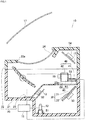
- a head-up display device 10 is installed in, for example, a vehicle.
- An occupant (operator) Mn recognizes virtual images V1 and V2 based on images projected onto a front glass 17 (projection surface 17) .
- the head-up display device 10 includes a case 20, a light-emitting device 12, provided at the bottom of the case 20, that can emit an image, a first flat mirror 13 reflecting light emitted from the light-emitting device 12, a reflecting mirror 30 on which the light reflected by the first flat mirror 13 is incident, a screen 40 through which the light reflected by reflecting mirror 30 passes, a second flat mirror 15 reflecting the light having passed through the screen 40, a concave mirror 16 on which the light reflected by the second flat mirror 15 is incident, the front glass 17 onto which the light reflected by the concave mirror 16 is projected, and a control unit 18 capable of controlling the light-emitting device 12 and the screen 40.
- a lower case 21 opened toward upward is covered with an upper case 22 and an inner lid 23 is disposed in the lower case 21.
- the lower case 21, the upper case 22, and the inner lid 23 are formed by, for example, black synthetic resin having light shielding properties.
- An opening 22a is formed in the upper surface of the upper case 22. This opening 22a is provided with a cover 24 made of transparent resin.
- the inner lid 23 is provided to block external light such as sunlight. On the other hand, a part of the inner lid 23 is provided with an opening 23a through which the light emitted from the light-emitting device 12 passes.
- the light-emitting device 12 is supported by a stay 51 fixed to the bottom of the lower case 21.
- a reflective display element such as a DMD (Digital Micromirror Device) or a LCOS (registered trademark: Liquid Crystal On Silicon) or a transmissive display element such as a TFT (Thin Film Transistor) liquid crystal panel may be adopted.
- the first flat mirror 13 is supported by a stay 52 fixed to the side wall of the lower case 21.
- the first flat mirror 13 is obtained by forming a reflecting film on the surface of a base material made of, for example, synthetic resin or a glass material using a method such as vapor deposition.
- the reflecting mirror 30 is supported by a stay 53 fixed to the side wall of the lower case 21.
- the reflecting mirror 30 is obtained by forming a reflecting film on the surface of a base material made of, for example, synthetic resin or a glass material using a method such as vapor deposition.
- the surface of the reflecting mirror 30 includes two reflecting surfaces 31 and 32 having different shapes. One of them is the first reflecting surface 31 formed in a flat mirror and the other is the second reflecting surface 32 formed in a convex mirror. The first reflecting surface 31 and the second reflecting surface 32 are formed on one base material.
- first reflecting surface 31 may be a curved surface that is bent instead of a flat surface.
- second reflecting surface 32 may be a flat surface instead of a curved surface.
- both the first reflecting surface 31 and the second reflecting surface 32 may be curved surfaces. When both the first reflecting surface 31 and the second reflecting surface 32 are curved surfaces, their shapes need to be different from each other. The reason will be described later.
- the screen 40 is supported by a screen holder 60.
- the screen 40 includes a first screen 41 through which the light reflected by the first reflecting surface 31 passes and a second screen 42 through which the light reflected by the second reflecting surface 32 passes.
- the first screen 41 is a translucent screen that receives the light emitted from the light-emitting device 12 on the back surface thereof and displays a display image on the front surface.
- a holographic diffuser, a microlens array, or a diffusion plate can be adopted as the first screen 41.
- the second screen 42 is similar to the first screen 41.
- the length of a first optical path L1 from the first screen 41 to the front glass 17 is longer than the length of a second optical path L2 from the second screen 42 to the front glass 17. That is, the first screen 41 and the second screen 42 are disposed so that the length of the first optical path L1 in which the light having passed through the first screen 41 reaches the front glass 17 is different from the length of the second optical path L2 in which the light having passed through the second screen 42 reaches the front glass 17.
- the screen holder 60 is fixed to stays 55 and 55 mounted to the side wall of the lower case 21.
- the screen holder 60 includes a first cylindrical part 61 supporting the first screen 41 and a second cylindrical part 62 supporting the second screen 42.
- the optical axis of the first screen 41 and the optical axis of the second screen 42 are disposed along the optical axes of the transmitting light. Accordingly, the first screen 41 and/or the second screen 42 may be inclined as appropriate with respect to the optical axes of the transmitting light.
- the images projected onto the front glass 17 can be inclined by inclining the screens.
- the second flat mirror 15 is supported by a stay 54 fixed to the side wall of the upper case 22.
- the second flat mirror 15 is obtained by forming a reflecting film on the surface of a base material made of, for example, synthetic resin or a glass material using a method such as vapor deposition.
- the concave mirror 16 is rotatably supported on the side wall of the upper case 22.
- the concave mirror 16 is obtained by forming a reflecting film on the surface of a base material made of, for example, a synthetic resin material using a method such as vapor deposition.
- the concave mirror 16 is a mirror having a free curved surface and further reflects the light reflected by the second flat mirror 15 to the front glass 17.
- the light-emitting device 12 emits light to the first flat mirror 13 based on a control signal from the control unit 18.
- the emitted light is reflected to the reflecting mirror 30 by the first flat mirror 13.
- the reflected light is incident on the first reflecting surface 31 or the second reflecting surface 32. Whether light is incident on the first reflecting surface 31 or the second reflecting surface 32 depends on the incident position on the first flat mirror 13.
- the light incident on the first reflecting surface 31 is reflected to the first screen 41.
- the reflected light passes through the opening 23a and passes through the first screen 41.
- the image to be projected onto the front glass 17 is focused by passing through the first screen 41.
- the light incident on the second reflecting surface 32 is reflected to the second screen 42.
- the reflected light passes through the opening 23a and almost passes through the second screen 42.
- the image to be projected onto the front glass 17 is focused by passing through the second screen 42.
- the light reflected by the first reflecting surface 31 or the second reflecting surface 32 is reflected by the second flat mirror 15, reflected by the concave mirror 16, and passes through the cover 24.
- the light having passed through the cover 24 is projected onto the front glass 17.
- the occupant Mn recognizes the images projected onto the front glass 17 as the virtual images V1 and V2 that appear in front of the front glass 17.
- the range of the front glass 17 to which light is projected is referred to as an eye box that can be visually recognized by the occupant Mn.
- the light-emitting device 12 emits an image having been distorted in advance.
- the first screen 41 and the second screen 42 are disposed so that the length of the first optical path L1 is different from the length of the second optical path L2.
- the occupant Mn recognizes the image focused on the first screen 41 and the image focused on the second screen 42 so that one is projected closer to the other (see the virtual images V1 and V2). That is, a sense of depth can be generated.
- the distance from the reflecting mirror 30 to the first screen 41 is different from the distance from the reflecting mirror 30 to the second screen 42.
- the shapes are different from each other. That is, the shape of the first reflecting surface 31 is different from the shape of the second reflecting surface 32 so as to enable focusing on the first screen 41 and the second screen 42 having different distances from the reflecting mirror 30. This enables adjustment of focusing distances appropriate for them.
- the necessary number of the reflecting mirrors 30 is one. Accordingly, the number of the light-emitting devices 12 emitting light to the reflecting mirror 30 is only one. Since the number of the light-emitting devices 12 is only one, the head-up display device 10 can be low-cost and compact.
- the low-cost and compact head-up display device 10 capable of generating a sense of depth in the virtual images V1 and V2.
- the head-up display device 10 illustrated in Fig. 1 has the following problems.
- the second reflecting surface 32 is configured by a convex mirror. Accordingly, the light reflected by the second reflecting surface 32 is expanded toward the second screen 42. Accordingly, a part of the light (curved surface reflected light) reflected by the second reflecting surface 32 does not pass through the second screen 42. This is problematic in terms of the efficient use of the light emitted from the light-emitting device 12.
- the size of the second screen 42 needs to be increased. Since the size of the head-up display device 10 is increased in this case, this is also problematic.
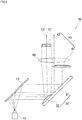
- Fig. 4 illustrates the cross-sectional structure of a head-up display device 70 in an example so as to correspond to Fig. 1 .
- the head-up display device 70 according to the invention further improves the problems of the head-up display device 10 in the reference example (see Fig. 1 ). More specifically, a lens 80 is provided below the second screen 42.
- the basic structure other than this is the same as in the head-up display device in the reference example. Details will be described below.
- the second screen 42 and the lens 80 are supported by the second cylindrical part 62 of the screen holder 60.
- the lens 80 is disposed closer to the light-emitting device 12 than the second screen 42 with respect to the optical path.
- the first screen 41, the second screen 42, and the lens 80 are supported by the screen holder 60.
- the screen holder 60 is configured by forming the first cylindrical part 61 supporting the first screen 41 integrally with the second cylindrical part 62 supporting the second screen 42 and the lens 80. By supporting these components using the cylindrical parts 61 and 62 separated from each other, it is possible to prevent the light that originally passes through the second screen 42 from passing through the first screen 41.
- the cylindrical parts 61 and 62 are formed integrally, the screens 41 and 42 and the lens 80 can be disposed in relatively accurate positions.
- a convex lens is adopted as the lens 80 (specifically, this convex lens does not have the portion of a general convex lens indicated by the dot-dot-dash line).
- a toroidal lens having a toroidally curved surface or a free curved surface lens having a free curved surface can be used as the lens 80.
- the curvature radius of a first cross section in the longitudinal direction of the second screen 42 is desirably larger than the curvature radius of a second cross section orthogonal to the first cross section.
- An optical axis C1 of the lens 80 is offset with respect to an optical axis C2 of the second screen 42 through which the light (curved surface reflected light) reflected by the second reflecting surface 32 passes.
- the optical axis C1 of the lens 80 coincides with the optical axis of the light-emitting device 12. Accordingly, the optical axis C1 can also be the optical axis C1 of the light-emitting device 12.
- the optical axis C1 of the lens 80 does not need to be offset with respect to the optical axis C2 of the second screen 42.
- the head-up display device 70 according to the invention also has the following effects.
- the lens 80 capable of converging light is provided between the second screen 42 (screen through which curved surface reflected light passes) and the light-emitting device 12.
- the light reflected by the second reflecting surface 32 is reflected in various directions. Since the lens 80 capable of converging light is provided between the second screen 42 and the light-emitting device 12, the light reflected by the second reflecting surface 32 can pass through the second screen 42 without increasing the size of the second screen 42. It is possible to efficiently use the light emitted from the light-emitting device 12 without increasing the size of the head-up display device 70.
- the projection optical system of the head-up display device 70 including the concave mirror 16 and the front glass 17 may have different focal lengths between the vertical direction and the horizontal direction, the difference in the focal lengths can be corrected by the shape of the lens 80. This can make the illumination light distribution to the eye box of the head-up display device 70 efficient.
- the head-up display device according to the invention is installed in a vehicle in the example, the head-up display device is applicable to a conveyance other than a vehicle, such as a working machine, and a construction machine.
- the head-up display device according to the invention is not limited to a head-up display device that uses a front glass as the projection surface, it is also applicable to a so-called combiner integrated type head-up display device in which the projection surface is integrated.
- the invention is not limited to the examples as long as the working effects of the invention are obtained.
- the head-up display device according to the invention is suitable for a vehicle.
Landscapes
- Physics & Mathematics (AREA)
- Engineering & Computer Science (AREA)
- General Physics & Mathematics (AREA)
- Optics & Photonics (AREA)
- Chemical & Material Sciences (AREA)
- Combustion & Propulsion (AREA)
- Transportation (AREA)
- Mechanical Engineering (AREA)
- Instrument Panels (AREA)
Abstract
Description
- The present invention relates to an improved head-up display device.
- A conveyance such as a vehicle may have a head-up display device capable of projecting information to the front side of an occupant. The occupant can obtain the information by visually recognizing a virtual image projected to the front side. The technique disclosed in PTL 1 is related art concerning a head-up display device.
- A head-up display device as described in PTL 1 includes a first display for displaying a first image, a second display for displaying a second image, a half mirror through which light from the first display passes and which reflects light from the second display, and a front glass (projection surface) onto which light having passed through or being reflected by the half mirror is projected.
- As for the lengths of optical paths through which light passes, the length of the optical path from the first display to the front glass is longer than the length of the optical path from the second display to the front glass. This causes the occupant to recognize the first image and the second image closer to the first image. That is, it is possible to generate a sense of depth in a virtual image by projecting the images having different lengths of the optical paths onto the front glass.
- However, the head-up display device as described above needs to have two displays for emitting two different types of images. Accordingly, the cost of components becomes high and the device size becomes large.
- PTL 1:
JP-A-2003-237412 - An object of the invention is to provide a low-cost and compact head-up display device capable of generating a sense of depth in a virtual image.
- In a first aspect of the invention, there is provided a head-up display device including a light-emitting device capable of emitting an image to be projected onto a projection surface, a reflecting mirror reflecting light emitted from the light-emitting device, and a screen on which the light reflected by the reflecting mirror is focused and through which the light passes, in which the reflecting mirror has at least first and second reflecting surfaces, the light emitted from the light-emitting device being incident on the first and second reflecting surfaces, one and the other of the first and second reflecting surfaces are a flat surface and a curved surface or curved surfaces having different shapes, the screen includes a first screen through which the light reflected by the first reflecting surface passes and a second screen through which the light reflected by the second reflecting surface passes, the first screen and the second screen are disposed so that a length of a first optical path in which the light having passed through the first screen reaches the projection surface is different from a length of a second optical path in which the light having passed through the second screen reaches the projection surface, and, when the light reflected by the first reflecting surface that is a curved surface and/or the second reflecting surface that is a curved surface is curved surface reflected light, a lens capable of converging light is provided between the screen through which the curved surface reflected light passes and the light-emitting device.
- In a second aspect, the lens is preferably a convex lens, a toroidal lens, or a free curved surface lens.
- In a third aspect, an optical axis of the lens is preferably offset with respect to an optical axis of the screen through which the curved surface reflected light passes.
- In the first aspect of the invention, the first screen and the second screen are disposed so that the length of the first optical path is different from the length of the second optical path. The operator of the head-up display device recognizes the image focused on the first screen and the image focused on the second screen so that one is closer to the other. That is, a sense of depth can be generated.
- On the other hand, since the first screen and the second screen are disposed so that the length of the first optical path is different from the length of the second optical path, the distance from the reflecting mirror to the first screen is different from the distance from the reflecting mirror to the second screen. Of the first reflecting surface and the second reflecting surface of the reflecting mirror, one is a flat surface and the other is a curved surface or both surfaces are curved surfaces having different shapes. That is, the shape of the first reflecting surface is different from the shape of the second reflecting surface so as to enable focusing on the first screen and the second screen having different distances from the reflecting mirror. This enables adjustment of focusing distances appropriate for them. At this time, the necessary number of the reflecting mirrors is one. Accordingly, the number of the light-emitting devices emitting light to the reflecting mirror is only one. Since the number of the light-emitting devices is only one, the head-up display device can be low-cost and compact.
- Accordingly, it is possible to provide the low-cost and compact head-up display device capable of generating a sense of depth in the virtual images.
- In addition, a lens capable of converging light is provided between the screen through which the curved surface reflected light passes and the light-emitting device. The curved surface reflected light is reflected in various directions. Since the lens capable of converging light is provided between the screen and the light-emitting device, the curved surface reflected light can pass through the screen without increasing the size of the screen. It is possible to efficiently use the light emitted from the light-emitting device without increasing the size of the head-up display device.
- According to the second aspect of the invention, it is possible to control illumination light distribution for adjusting the light distribution with respect to a focal length in a projection optical system of the head-up display device. This can make the illumination light distribution to an eye box of the head-up display device efficient.
- According to the third aspect of the invention, it is possible to direct, to a predetermined position of the eye box, the light that passes through the screen through which the curved surface reflected light passes, thereby improving the uniformity of the light in the eye box.
-
- [
Fig. 1] Fig. 1 is a cross sectional view illustrating a head-up display device in a reference example that is a premise of a head-up display device according to the invention. - [
Fig. 2] Fig. 2 illustrates the operation of the head-up display device illustrated inFig. 1 . - [
Fig. 3] Fig. 3 illustrates problems of the head-up display device illustrated inFig. 1 . - [
Fig. 4] Fig. 4 is a cross sectional view illustrating a head-up display device according to an example of the invention. - [
Fig. 5] Fig. 5 is an enlarged view illustrating a main part of the head-up display device illustrated inFig. 4 . - Embodiments of the invention will be described with reference to the drawings. It should be noted that the left and the right are based on the occupant of a vehicle and the front and the rear are based on the travel direction of the vehicle in the following description.
- First, a head-up display device according to a reference example that is a premise of the invention will be described.
- See
Figs. 1 and2 . A head-updisplay device 10 is installed in, for example, a vehicle. An occupant (operator) Mn recognizes virtual images V1 and V2 based on images projected onto a front glass 17 (projection surface 17) . - The head-up
display device 10 includes acase 20, a light-emitting device 12, provided at the bottom of thecase 20, that can emit an image, a firstflat mirror 13 reflecting light emitted from the light-emitting device 12, areflecting mirror 30 on which the light reflected by the firstflat mirror 13 is incident, ascreen 40 through which the light reflected by reflectingmirror 30 passes, a secondflat mirror 15 reflecting the light having passed through thescreen 40, aconcave mirror 16 on which the light reflected by the secondflat mirror 15 is incident, thefront glass 17 onto which the light reflected by theconcave mirror 16 is projected, and acontrol unit 18 capable of controlling the light-emitting device 12 and thescreen 40. - See
Fig. 1 . In thecase 20, alower case 21 opened toward upward is covered with anupper case 22 and aninner lid 23 is disposed in thelower case 21. Thelower case 21, theupper case 22, and theinner lid 23 are formed by, for example, black synthetic resin having light shielding properties. - An opening 22a is formed in the upper surface of the
upper case 22. This opening 22a is provided with acover 24 made of transparent resin. - The
inner lid 23 is provided to block external light such as sunlight. On the other hand, a part of theinner lid 23 is provided with an opening 23a through which the light emitted from the light-emittingdevice 12 passes. - The light-
emitting device 12 is supported by astay 51 fixed to the bottom of thelower case 21. As the light-emitting device 12, a reflective display element such as a DMD (Digital Micromirror Device) or a LCOS (registered trademark: Liquid Crystal On Silicon) or a transmissive display element such as a TFT (Thin Film Transistor) liquid crystal panel may be adopted. - The first
flat mirror 13 is supported by astay 52 fixed to the side wall of thelower case 21. The firstflat mirror 13 is obtained by forming a reflecting film on the surface of a base material made of, for example, synthetic resin or a glass material using a method such as vapor deposition. - The reflecting
mirror 30 is supported by astay 53 fixed to the side wall of thelower case 21. The reflectingmirror 30 is obtained by forming a reflecting film on the surface of a base material made of, for example, synthetic resin or a glass material using a method such as vapor deposition. - The surface of the reflecting
mirror 30 includes two reflectingsurfaces surface 31 formed in a flat mirror and the other is the second reflectingsurface 32 formed in a convex mirror. The first reflectingsurface 31 and the second reflectingsurface 32 are formed on one base material. - It should be noted that the first reflecting
surface 31 may be a curved surface that is bent instead of a flat surface. In addition, the second reflectingsurface 32 may be a flat surface instead of a curved surface. In addition, both the first reflectingsurface 31 and the second reflectingsurface 32 may be curved surfaces. When both the first reflectingsurface 31 and the second reflectingsurface 32 are curved surfaces, their shapes need to be different from each other. The reason will be described later. - The
screen 40 is supported by ascreen holder 60. Thescreen 40 includes afirst screen 41 through which the light reflected by the first reflectingsurface 31 passes and asecond screen 42 through which the light reflected by the second reflectingsurface 32 passes. - The
first screen 41 is a translucent screen that receives the light emitted from the light-emittingdevice 12 on the back surface thereof and displays a display image on the front surface. For example, a holographic diffuser, a microlens array, or a diffusion plate can be adopted as thefirst screen 41. Thesecond screen 42 is similar to thefirst screen 41. - With respect to the lengths of the optical paths of the light having passed through the
screens first screen 41 to thefront glass 17 is longer than the length of a second optical path L2 from thesecond screen 42 to thefront glass 17. That is, thefirst screen 41 and thesecond screen 42 are disposed so that the length of the first optical path L1 in which the light having passed through thefirst screen 41 reaches thefront glass 17 is different from the length of the second optical path L2 in which the light having passed through thesecond screen 42 reaches thefront glass 17. - The
screen holder 60 is fixed to stays 55 and 55 mounted to the side wall of thelower case 21. Thescreen holder 60 includes a firstcylindrical part 61 supporting thefirst screen 41 and a secondcylindrical part 62 supporting thesecond screen 42. - It should be noted that the optical axis of the
first screen 41 and the optical axis of thesecond screen 42 are disposed along the optical axes of the transmitting light. Accordingly, thefirst screen 41 and/or thesecond screen 42 may be inclined as appropriate with respect to the optical axes of the transmitting light. The images projected onto thefront glass 17 can be inclined by inclining the screens. - The second
flat mirror 15 is supported by astay 54 fixed to the side wall of theupper case 22. The secondflat mirror 15 is obtained by forming a reflecting film on the surface of a base material made of, for example, synthetic resin or a glass material using a method such as vapor deposition. - The
concave mirror 16 is rotatably supported on the side wall of theupper case 22. Theconcave mirror 16 is obtained by forming a reflecting film on the surface of a base material made of, for example, a synthetic resin material using a method such as vapor deposition. Theconcave mirror 16 is a mirror having a free curved surface and further reflects the light reflected by the secondflat mirror 15 to thefront glass 17. - The light-emitting
device 12 emits light to the firstflat mirror 13 based on a control signal from thecontrol unit 18. The emitted light is reflected to the reflectingmirror 30 by the firstflat mirror 13. The reflected light is incident on the first reflectingsurface 31 or the second reflectingsurface 32. Whether light is incident on the first reflectingsurface 31 or the second reflectingsurface 32 depends on the incident position on the firstflat mirror 13. - The light incident on the first reflecting
surface 31 is reflected to thefirst screen 41. The reflected light passes through theopening 23a and passes through thefirst screen 41. The image to be projected onto thefront glass 17 is focused by passing through thefirst screen 41. - The light incident on the second reflecting
surface 32 is reflected to thesecond screen 42. The reflected light passes through theopening 23a and almost passes through thesecond screen 42. The image to be projected onto thefront glass 17 is focused by passing through thesecond screen 42. - The light reflected by the first reflecting
surface 31 or the second reflectingsurface 32 is reflected by the secondflat mirror 15, reflected by theconcave mirror 16, and passes through thecover 24. The light having passed through thecover 24 is projected onto thefront glass 17. The occupant Mn recognizes the images projected onto thefront glass 17 as the virtual images V1 and V2 that appear in front of thefront glass 17. The range of thefront glass 17 to which light is projected is referred to as an eye box that can be visually recognized by the occupant Mn. - Since the
concave mirror 16 and thefront glass 17 are curved, the image focused on thescreen 40 is also distorted. Accordingly, to prevent the virtual image recognized by the occupant from being distorted, the light-emittingdevice 12 emits an image having been distorted in advance. - In the head-up
display device 10 as described above, the following effects are obtained. - See
Fig. 2 . Thefirst screen 41 and thesecond screen 42 are disposed so that the length of the first optical path L1 is different from the length of the second optical path L2. The occupant Mn recognizes the image focused on thefirst screen 41 and the image focused on thesecond screen 42 so that one is projected closer to the other (see the virtual images V1 and V2). That is, a sense of depth can be generated. - On the other hand, since the
first screen 41 and thesecond screen 42 are disposed so that the length of the first optical path L1 is different from the length of the second optical path L2, the distance from the reflectingmirror 30 to thefirst screen 41 is different from the distance from the reflectingmirror 30 to thesecond screen 42. At this time, in the first reflectingsurface 31 and the second reflectingsurface 32 of the reflectingmirror 30, since one reflecting surface (first reflecting surface 31) is a flat surface and the other reflecting surface (second reflecting surface 32) is a curved surface, the shapes are different from each other. That is, the shape of the first reflectingsurface 31 is different from the shape of the second reflectingsurface 32 so as to enable focusing on thefirst screen 41 and thesecond screen 42 having different distances from the reflectingmirror 30. This enables adjustment of focusing distances appropriate for them. At this time, the necessary number of the reflecting mirrors 30 is one. Accordingly, the number of the light-emittingdevices 12 emitting light to the reflectingmirror 30 is only one. Since the number of the light-emittingdevices 12 is only one, the head-updisplay device 10 can be low-cost and compact. - Accordingly, it is possible to provide the low-cost and compact head-up
display device 10 capable of generating a sense of depth in the virtual images V1 and V2. - See
Fig. 3 . As a result of the study by the inventor et al., the head-updisplay device 10 illustrated inFig. 1 has the following problems. - See
Fig. 3 . The second reflectingsurface 32 is configured by a convex mirror. Accordingly, the light reflected by the second reflectingsurface 32 is expanded toward thesecond screen 42. Accordingly, a part of the light (curved surface reflected light) reflected by the second reflectingsurface 32 does not pass through thesecond screen 42. This is problematic in terms of the efficient use of the light emitted from the light-emittingdevice 12. - In contrast, in order to pass all of the light reflected by the second reflecting
surface 32 through thesecond screen 42, the size of thesecond screen 42 needs to be increased. Since the size of the head-updisplay device 10 is increased in this case, this is also problematic. - Even when the second reflecting
surface 32 is configured by a concave mirror, if thesecond screen 42 is disposed in a position more remote from the focal distance of the mirror, similar problems occur. That is, such problems are not limited to a convex mirror. - Next, examples of the invention will be described with reference to the drawings.
- See
Fig. 4. Fig. 4 illustrates the cross-sectional structure of a head-updisplay device 70 in an example so as to correspond toFig. 1 . The head-updisplay device 70 according to the invention further improves the problems of the head-updisplay device 10 in the reference example (seeFig. 1 ). More specifically, alens 80 is provided below thesecond screen 42. The basic structure other than this is the same as in the head-up display device in the reference example. Details will be described below. - It should be noted that components common to those of the head-up display device in the reference example are given the same reference numerals and detailed descriptions are omitted.
- The
second screen 42 and thelens 80 are supported by the secondcylindrical part 62 of thescreen holder 60. Thelens 80 is disposed closer to the light-emittingdevice 12 than thesecond screen 42 with respect to the optical path. - The
first screen 41, thesecond screen 42, and thelens 80 are supported by thescreen holder 60. Thescreen holder 60 is configured by forming the firstcylindrical part 61 supporting thefirst screen 41 integrally with the secondcylindrical part 62 supporting thesecond screen 42 and thelens 80. By supporting these components using thecylindrical parts second screen 42 from passing through thefirst screen 41. In addition, since thecylindrical parts screens lens 80 can be disposed in relatively accurate positions. - See
Fig. 5 . A convex lens is adopted as the lens 80 (specifically, this convex lens does not have the portion of a general convex lens indicated by the dot-dot-dash line). Other than a convex lens, a toroidal lens having a toroidally curved surface or a free curved surface lens having a free curved surface can be used as thelens 80. In thelens 80, the curvature radius of a first cross section in the longitudinal direction of the second screen 42 (through which curved surface reflected light passes) is desirably larger than the curvature radius of a second cross section orthogonal to the first cross section. - An optical axis C1 of the
lens 80 is offset with respect to an optical axis C2 of thesecond screen 42 through which the light (curved surface reflected light) reflected by the second reflectingsurface 32 passes. In addition, the optical axis C1 of thelens 80 coincides with the optical axis of the light-emittingdevice 12. Accordingly, the optical axis C1 can also be the optical axis C1 of the light-emittingdevice 12. When a free curved surface lens is adopted as thelens 80, the optical axis C1 of thelens 80 does not need to be offset with respect to the optical axis C2 of thesecond screen 42. - As described above, the head-up
display device 70 according to the invention also has the following effects. - The
lens 80 capable of converging light is provided between the second screen 42 (screen through which curved surface reflected light passes) and the light-emittingdevice 12. The light reflected by the second reflectingsurface 32 is reflected in various directions. Since thelens 80 capable of converging light is provided between thesecond screen 42 and the light-emittingdevice 12, the light reflected by the second reflectingsurface 32 can pass through thesecond screen 42 without increasing the size of thesecond screen 42. It is possible to efficiently use the light emitted from the light-emittingdevice 12 without increasing the size of the head-updisplay device 70. - In addition, it is possible to control illumination light distribution for adjusting the light distribution with respect to a focal length in a projection optical system of the head-up
display device 70. Although the projection optical system of the head-updisplay device 70 including theconcave mirror 16 and thefront glass 17 may have different focal lengths between the vertical direction and the horizontal direction, the difference in the focal lengths can be corrected by the shape of thelens 80. This can make the illumination light distribution to the eye box of the head-updisplay device 70 efficient. - In addition, it is possible to direct, to a predetermined position of the eye box, the light that passes through the
second screen 42 through which the light reflected by the second reflectingsurface 32 passes, thereby improving the uniformity of light in the eye box. - Although the head-up display device according to the invention is installed in a vehicle in the example, the head-up display device is applicable to a conveyance other than a vehicle, such as a working machine, and a construction machine. In addition, the head-up display device according to the invention is not limited to a head-up display device that uses a front glass as the projection surface, it is also applicable to a so-called combiner integrated type head-up display device in which the projection surface is integrated.
- That is, the invention is not limited to the examples as long as the working effects of the invention are obtained.
- The head-up display device according to the invention is suitable for a vehicle.
-
- 12: light-emitting device
- 17: front glass (projection surface)
- 30: reflecting mirror
- 31: first reflecting surface
- 32: second reflecting surface
- 40: screen
- 41: first screen
- 42: second screen (screen through which curved surface reflected light passes)
- 70: head-up display device
- 80: lens
- C1: optical axis of lens
- C2: optical axis (optical axis of screen through which curved surface reflected light passes) of (second screen)
- L1: first optical path
- L2: second optical path
Claims (3)
- A head-up display device comprising:a light-emitting device capable of emitting an image to be projected onto a projection surface;a reflecting mirror reflecting light emitted from the light-emitting device; anda screen on which the light reflected by the reflecting mirror is focused and through which the light passes,wherein the reflecting mirror has at least first and second reflecting surfaces, the light emitted from the light-emitting device being incident on the first and second reflecting surfaces,one and the other of the first and second reflecting surfaces are a flat surface and a curved surface or curved surfaces having different shapes,the screen includes a first screen through which the light reflected by the first reflecting surface passes and a second screen through which the light reflected by the second reflecting surface passes,the first screen and the second screen are disposed so that a length of a first optical path in which the light having passed through the first screen reaches the projection surface is different from a length of a second optical path in which the light having passed through the second screen reaches the projection surface, andwhen the light reflected by the first reflecting surface that is a curved surface and/or the second reflecting surface that is a curved surface is curved surface reflected light, a lens capable of converging light is provided between the screen through which the curved surface reflected light passes and the light-emitting device.
- The head-up display device according to claim 1,
wherein the lens is a convex lens, a toroidal lens, or a free curved surface lens. - The head-up display device according to claim 1 or 2,
wherein an optical axis of the lens is offset with respect to an optical axis of the screen through which the curved surface reflected light passes.
Applications Claiming Priority (2)
| Application Number | Priority Date | Filing Date | Title |
|---|---|---|---|
| JP2015148896A JP6597022B2 (en) | 2015-07-28 | 2015-07-28 | Head-up display device |
| PCT/JP2016/070503 WO2017018198A1 (en) | 2015-07-28 | 2016-07-12 | Head-up display device |
Publications (3)
| Publication Number | Publication Date |
|---|---|
| EP3330769A1 true EP3330769A1 (en) | 2018-06-06 |
| EP3330769A4 EP3330769A4 (en) | 2019-03-13 |
| EP3330769B1 EP3330769B1 (en) | 2020-04-29 |
Family
ID=57885187
Family Applications (1)
| Application Number | Title | Priority Date | Filing Date |
|---|---|---|---|
| EP16830303.0A Active EP3330769B1 (en) | 2015-07-28 | 2016-07-12 | Head-up display device |
Country Status (4)
| Country | Link |
|---|---|
| US (1) | US10409061B2 (en) |
| EP (1) | EP3330769B1 (en) |
| JP (1) | JP6597022B2 (en) |
| WO (1) | WO2017018198A1 (en) |
Cited By (1)
| Publication number | Priority date | Publication date | Assignee | Title |
|---|---|---|---|---|
| EP3185061B1 (en) * | 2014-08-20 | 2019-02-27 | Nippon Seiki Co., Ltd. | Projection device and head-up display device |
Families Citing this family (9)
| Publication number | Priority date | Publication date | Assignee | Title |
|---|---|---|---|---|
| DE102017101699B3 (en) * | 2017-01-30 | 2018-05-09 | Visteon Global Technologies, Inc. | Display system for a vehicle and use of the display system in a vehicle |
| JP6830182B2 (en) * | 2017-03-08 | 2021-02-17 | パナソニックIpマネジメント株式会社 | Image projection device |
| JP6720903B2 (en) * | 2017-03-21 | 2020-07-08 | 株式会社デンソー | Head up display device |
| JP6717264B2 (en) * | 2017-06-08 | 2020-07-01 | 株式会社Jvcケンウッド | Virtual image display device, intermediate image forming unit, and image display light generation unit |
| WO2019039619A1 (en) * | 2017-08-22 | 2019-02-28 | 주식회사 세코닉스 | Heads-up display apparatus and method |
| EP3719560A4 (en) * | 2017-11-30 | 2021-08-04 | Nippon Seiki Co., Ltd. | Head-up display |
| JP2019215495A (en) * | 2018-06-14 | 2019-12-19 | パイオニア株式会社 | Display unit |
| JP7202191B2 (en) * | 2019-01-17 | 2023-01-11 | マクセル株式会社 | Vehicle information display system |
| US11169377B1 (en) * | 2020-09-16 | 2021-11-09 | E-Lead Electronic Co., Ltd. | Multi-focal plane head-up display |
Family Cites Families (14)
| Publication number | Priority date | Publication date | Assignee | Title |
|---|---|---|---|---|
| JPH0192718A (en) * | 1987-10-02 | 1989-04-12 | Canon Inc | Display method for correcting chromatic aberration generated by diffraction grating optical element, and executing image display by diffraction grating optical element |
| JPH075886U (en) * | 1993-06-25 | 1995-01-27 | 日本精機株式会社 | Vehicle display |
| JP4871459B2 (en) * | 2001-07-17 | 2012-02-08 | 矢崎総業株式会社 | In-vehicle head-up display device |
| JP2003237412A (en) | 2002-02-14 | 2003-08-27 | Denso Corp | Vehicular head-up display device |
| JP2005153811A (en) * | 2003-11-28 | 2005-06-16 | Nippon Seiki Co Ltd | Display apparatus for vehicle |
| JP4635490B2 (en) * | 2004-07-05 | 2011-02-23 | 凸版印刷株式会社 | Optical system and rear projection display device |
| JP2006106254A (en) * | 2004-10-04 | 2006-04-20 | Denso Corp | Head-up display for vehicle |
| JP5504833B2 (en) * | 2009-11-11 | 2014-05-28 | 株式会社ニコン | projector |
| JP5333943B2 (en) * | 2010-03-04 | 2013-11-06 | 日本精機株式会社 | Display device |
| US8277055B2 (en) * | 2010-07-21 | 2012-10-02 | Delphi Technologies, Inc. | Multiple view display system using a single projector and method of operating the same |
| JP2012179935A (en) * | 2011-02-28 | 2012-09-20 | Jvc Kenwood Corp | Display device for vehicle |
| JP2015034919A (en) | 2013-08-09 | 2015-02-19 | 株式会社デンソー | Information display device |
| JPWO2015159523A1 (en) * | 2014-04-14 | 2017-04-13 | パナソニックIpマネジメント株式会社 | Head-up display and mobile body equipped with head-up display |
| JP5930231B2 (en) * | 2014-08-20 | 2016-06-08 | 日本精機株式会社 | Projection device and head-up display device |
-
2015
- 2015-07-28 JP JP2015148896A patent/JP6597022B2/en active Active
-
2016
- 2016-07-12 US US15/744,010 patent/US10409061B2/en active Active
- 2016-07-12 EP EP16830303.0A patent/EP3330769B1/en active Active
- 2016-07-12 WO PCT/JP2016/070503 patent/WO2017018198A1/en active Application Filing
Cited By (1)
| Publication number | Priority date | Publication date | Assignee | Title |
|---|---|---|---|---|
| EP3185061B1 (en) * | 2014-08-20 | 2019-02-27 | Nippon Seiki Co., Ltd. | Projection device and head-up display device |
Also Published As
| Publication number | Publication date |
|---|---|
| JP6597022B2 (en) | 2019-10-30 |
| JP2017032600A (en) | 2017-02-09 |
| US10409061B2 (en) | 2019-09-10 |
| US20180210200A1 (en) | 2018-07-26 |
| WO2017018198A1 (en) | 2017-02-02 |
| EP3330769A4 (en) | 2019-03-13 |
| EP3330769B1 (en) | 2020-04-29 |
Similar Documents
| Publication | Publication Date | Title |
|---|---|---|
| EP3330769B1 (en) | Head-up display device | |
| US10302939B2 (en) | Projection device and head-up display device | |
| US10634909B2 (en) | Display device and head-up display | |
| CN106796352B (en) | Head-up display device | |
| WO2016208379A1 (en) | Screen device and head-up display device | |
| JP2018004817A (en) | Image display device and head-up display system | |
| JP2014174494A (en) | Virtual image display device | |
| EP3415973B1 (en) | Display device and head-up display | |
| JP2018205621A (en) | Virtual image display device, intermediate image forming part, and image display light generation unit | |
| US10488657B2 (en) | Head-up display device with uniform brightness | |
| JP2016173583A (en) | Projection device and head-up display device | |
| EP3677947A1 (en) | Headup display device | |
| JP2017142284A (en) | Display device and head-up display | |
| EP3511759B1 (en) | Virtual image display device | |
| JP2017097115A (en) | Screen device and head-up display device | |
| JP2019211504A (en) | Head-up display device |
Legal Events
| Date | Code | Title | Description |
|---|---|---|---|
| STAA | Information on the status of an ep patent application or granted ep patent |
Free format text: STATUS: THE INTERNATIONAL PUBLICATION HAS BEEN MADE |
|
| PUAI | Public reference made under article 153(3) epc to a published international application that has entered the european phase |
Free format text: ORIGINAL CODE: 0009012 |
|
| STAA | Information on the status of an ep patent application or granted ep patent |
Free format text: STATUS: REQUEST FOR EXAMINATION WAS MADE |
|
| 17P | Request for examination filed |
Effective date: 20180207 |
|
| AK | Designated contracting states |
Kind code of ref document: A1 Designated state(s): AL AT BE BG CH CY CZ DE DK EE ES FI FR GB GR HR HU IE IS IT LI LT LU LV MC MK MT NL NO PL PT RO RS SE SI SK SM TR |
|
| AX | Request for extension of the european patent |
Extension state: BA ME |
|
| DAV | Request for validation of the european patent (deleted) | ||
| DAX | Request for extension of the european patent (deleted) | ||
| A4 | Supplementary search report drawn up and despatched |
Effective date: 20190212 |
|
| RIC1 | Information provided on ipc code assigned before grant |
Ipc: G02B 27/01 20060101AFI20190206BHEP Ipc: B60K 35/00 20060101ALI20190206BHEP |
|
| GRAP | Despatch of communication of intention to grant a patent |
Free format text: ORIGINAL CODE: EPIDOSNIGR1 |
|
| STAA | Information on the status of an ep patent application or granted ep patent |
Free format text: STATUS: GRANT OF PATENT IS INTENDED |
|
| INTG | Intention to grant announced |
Effective date: 20191220 |
|
| GRAS | Grant fee paid |
Free format text: ORIGINAL CODE: EPIDOSNIGR3 |
|
| GRAA | (expected) grant |
Free format text: ORIGINAL CODE: 0009210 |
|
| STAA | Information on the status of an ep patent application or granted ep patent |
Free format text: STATUS: THE PATENT HAS BEEN GRANTED |
|
| AK | Designated contracting states |
Kind code of ref document: B1 Designated state(s): AL AT BE BG CH CY CZ DE DK EE ES FI FR GB GR HR HU IE IS IT LI LT LU LV MC MK MT NL NO PL PT RO RS SE SI SK SM TR |
|
| REG | Reference to a national code |
Ref country code: GB Ref legal event code: FG4D |
|
| REG | Reference to a national code |
Ref country code: CH Ref legal event code: EP |
|
| REG | Reference to a national code |
Ref country code: AT Ref legal event code: REF Ref document number: 1264184 Country of ref document: AT Kind code of ref document: T Effective date: 20200515 |
|
| REG | Reference to a national code |
Ref country code: DE Ref legal event code: R096 Ref document number: 602016035323 Country of ref document: DE |
|
| REG | Reference to a national code |
Ref country code: IE Ref legal event code: FG4D |
|
| REG | Reference to a national code |
Ref country code: NL Ref legal event code: MP Effective date: 20200429 |
|
| REG | Reference to a national code |
Ref country code: LT Ref legal event code: MG4D |
|
| PG25 | Lapsed in a contracting state [announced via postgrant information from national office to epo] |
Ref country code: LT Free format text: LAPSE BECAUSE OF FAILURE TO SUBMIT A TRANSLATION OF THE DESCRIPTION OR TO PAY THE FEE WITHIN THE PRESCRIBED TIME-LIMIT Effective date: 20200429 Ref country code: SE Free format text: LAPSE BECAUSE OF FAILURE TO SUBMIT A TRANSLATION OF THE DESCRIPTION OR TO PAY THE FEE WITHIN THE PRESCRIBED TIME-LIMIT Effective date: 20200429 Ref country code: NO Free format text: LAPSE BECAUSE OF FAILURE TO SUBMIT A TRANSLATION OF THE DESCRIPTION OR TO PAY THE FEE WITHIN THE PRESCRIBED TIME-LIMIT Effective date: 20200729 Ref country code: PT Free format text: LAPSE BECAUSE OF FAILURE TO SUBMIT A TRANSLATION OF THE DESCRIPTION OR TO PAY THE FEE WITHIN THE PRESCRIBED TIME-LIMIT Effective date: 20200831 Ref country code: IS Free format text: LAPSE BECAUSE OF FAILURE TO SUBMIT A TRANSLATION OF THE DESCRIPTION OR TO PAY THE FEE WITHIN THE PRESCRIBED TIME-LIMIT Effective date: 20200829 Ref country code: FI Free format text: LAPSE BECAUSE OF FAILURE TO SUBMIT A TRANSLATION OF THE DESCRIPTION OR TO PAY THE FEE WITHIN THE PRESCRIBED TIME-LIMIT Effective date: 20200429 Ref country code: GR Free format text: LAPSE BECAUSE OF FAILURE TO SUBMIT A TRANSLATION OF THE DESCRIPTION OR TO PAY THE FEE WITHIN THE PRESCRIBED TIME-LIMIT Effective date: 20200730 |
|
| REG | Reference to a national code |
Ref country code: AT Ref legal event code: MK05 Ref document number: 1264184 Country of ref document: AT Kind code of ref document: T Effective date: 20200429 |
|
| PG25 | Lapsed in a contracting state [announced via postgrant information from national office to epo] |
Ref country code: LV Free format text: LAPSE BECAUSE OF FAILURE TO SUBMIT A TRANSLATION OF THE DESCRIPTION OR TO PAY THE FEE WITHIN THE PRESCRIBED TIME-LIMIT Effective date: 20200429 Ref country code: HR Free format text: LAPSE BECAUSE OF FAILURE TO SUBMIT A TRANSLATION OF THE DESCRIPTION OR TO PAY THE FEE WITHIN THE PRESCRIBED TIME-LIMIT Effective date: 20200429 Ref country code: RS Free format text: LAPSE BECAUSE OF FAILURE TO SUBMIT A TRANSLATION OF THE DESCRIPTION OR TO PAY THE FEE WITHIN THE PRESCRIBED TIME-LIMIT Effective date: 20200429 Ref country code: BG Free format text: LAPSE BECAUSE OF FAILURE TO SUBMIT A TRANSLATION OF THE DESCRIPTION OR TO PAY THE FEE WITHIN THE PRESCRIBED TIME-LIMIT Effective date: 20200729 |
|
| PG25 | Lapsed in a contracting state [announced via postgrant information from national office to epo] |
Ref country code: NL Free format text: LAPSE BECAUSE OF FAILURE TO SUBMIT A TRANSLATION OF THE DESCRIPTION OR TO PAY THE FEE WITHIN THE PRESCRIBED TIME-LIMIT Effective date: 20200429 Ref country code: AL Free format text: LAPSE BECAUSE OF FAILURE TO SUBMIT A TRANSLATION OF THE DESCRIPTION OR TO PAY THE FEE WITHIN THE PRESCRIBED TIME-LIMIT Effective date: 20200429 |
|
| PG25 | Lapsed in a contracting state [announced via postgrant information from national office to epo] |
Ref country code: CZ Free format text: LAPSE BECAUSE OF FAILURE TO SUBMIT A TRANSLATION OF THE DESCRIPTION OR TO PAY THE FEE WITHIN THE PRESCRIBED TIME-LIMIT Effective date: 20200429 Ref country code: RO Free format text: LAPSE BECAUSE OF FAILURE TO SUBMIT A TRANSLATION OF THE DESCRIPTION OR TO PAY THE FEE WITHIN THE PRESCRIBED TIME-LIMIT Effective date: 20200429 Ref country code: ES Free format text: LAPSE BECAUSE OF FAILURE TO SUBMIT A TRANSLATION OF THE DESCRIPTION OR TO PAY THE FEE WITHIN THE PRESCRIBED TIME-LIMIT Effective date: 20200429 Ref country code: DK Free format text: LAPSE BECAUSE OF FAILURE TO SUBMIT A TRANSLATION OF THE DESCRIPTION OR TO PAY THE FEE WITHIN THE PRESCRIBED TIME-LIMIT Effective date: 20200429 Ref country code: SM Free format text: LAPSE BECAUSE OF FAILURE TO SUBMIT A TRANSLATION OF THE DESCRIPTION OR TO PAY THE FEE WITHIN THE PRESCRIBED TIME-LIMIT Effective date: 20200429 Ref country code: IT Free format text: LAPSE BECAUSE OF FAILURE TO SUBMIT A TRANSLATION OF THE DESCRIPTION OR TO PAY THE FEE WITHIN THE PRESCRIBED TIME-LIMIT Effective date: 20200429 Ref country code: EE Free format text: LAPSE BECAUSE OF FAILURE TO SUBMIT A TRANSLATION OF THE DESCRIPTION OR TO PAY THE FEE WITHIN THE PRESCRIBED TIME-LIMIT Effective date: 20200429 Ref country code: AT Free format text: LAPSE BECAUSE OF FAILURE TO SUBMIT A TRANSLATION OF THE DESCRIPTION OR TO PAY THE FEE WITHIN THE PRESCRIBED TIME-LIMIT Effective date: 20200429 |
|
| REG | Reference to a national code |
Ref country code: DE Ref legal event code: R097 Ref document number: 602016035323 Country of ref document: DE |
|
| PG25 | Lapsed in a contracting state [announced via postgrant information from national office to epo] |
Ref country code: PL Free format text: LAPSE BECAUSE OF FAILURE TO SUBMIT A TRANSLATION OF THE DESCRIPTION OR TO PAY THE FEE WITHIN THE PRESCRIBED TIME-LIMIT Effective date: 20200429 Ref country code: SK Free format text: LAPSE BECAUSE OF FAILURE TO SUBMIT A TRANSLATION OF THE DESCRIPTION OR TO PAY THE FEE WITHIN THE PRESCRIBED TIME-LIMIT Effective date: 20200429 Ref country code: MC Free format text: LAPSE BECAUSE OF FAILURE TO SUBMIT A TRANSLATION OF THE DESCRIPTION OR TO PAY THE FEE WITHIN THE PRESCRIBED TIME-LIMIT Effective date: 20200429 |
|
| REG | Reference to a national code |
Ref country code: CH Ref legal event code: PL |
|
| PLBE | No opposition filed within time limit |
Free format text: ORIGINAL CODE: 0009261 |
|
| STAA | Information on the status of an ep patent application or granted ep patent |
Free format text: STATUS: NO OPPOSITION FILED WITHIN TIME LIMIT |
|
| GBPC | Gb: european patent ceased through non-payment of renewal fee |
Effective date: 20200729 |
|
| 26N | No opposition filed |
Effective date: 20210201 |
|
| REG | Reference to a national code |
Ref country code: BE Ref legal event code: MM Effective date: 20200731 |
|
| PG25 | Lapsed in a contracting state [announced via postgrant information from national office to epo] |
Ref country code: FR Free format text: LAPSE BECAUSE OF NON-PAYMENT OF DUE FEES Effective date: 20200731 Ref country code: GB Free format text: LAPSE BECAUSE OF NON-PAYMENT OF DUE FEES Effective date: 20200729 Ref country code: CH Free format text: LAPSE BECAUSE OF NON-PAYMENT OF DUE FEES Effective date: 20200731 Ref country code: LU Free format text: LAPSE BECAUSE OF NON-PAYMENT OF DUE FEES Effective date: 20200712 Ref country code: LI Free format text: LAPSE BECAUSE OF NON-PAYMENT OF DUE FEES Effective date: 20200731 |
|
| PG25 | Lapsed in a contracting state [announced via postgrant information from national office to epo] |
Ref country code: BE Free format text: LAPSE BECAUSE OF NON-PAYMENT OF DUE FEES Effective date: 20200731 Ref country code: SI Free format text: LAPSE BECAUSE OF FAILURE TO SUBMIT A TRANSLATION OF THE DESCRIPTION OR TO PAY THE FEE WITHIN THE PRESCRIBED TIME-LIMIT Effective date: 20200429 |
|
| PG25 | Lapsed in a contracting state [announced via postgrant information from national office to epo] |
Ref country code: IE Free format text: LAPSE BECAUSE OF NON-PAYMENT OF DUE FEES Effective date: 20200712 |
|
| PG25 | Lapsed in a contracting state [announced via postgrant information from national office to epo] |
Ref country code: TR Free format text: LAPSE BECAUSE OF FAILURE TO SUBMIT A TRANSLATION OF THE DESCRIPTION OR TO PAY THE FEE WITHIN THE PRESCRIBED TIME-LIMIT Effective date: 20200429 Ref country code: MT Free format text: LAPSE BECAUSE OF FAILURE TO SUBMIT A TRANSLATION OF THE DESCRIPTION OR TO PAY THE FEE WITHIN THE PRESCRIBED TIME-LIMIT Effective date: 20200429 Ref country code: CY Free format text: LAPSE BECAUSE OF FAILURE TO SUBMIT A TRANSLATION OF THE DESCRIPTION OR TO PAY THE FEE WITHIN THE PRESCRIBED TIME-LIMIT Effective date: 20200429 |
|
| PG25 | Lapsed in a contracting state [announced via postgrant information from national office to epo] |
Ref country code: MK Free format text: LAPSE BECAUSE OF FAILURE TO SUBMIT A TRANSLATION OF THE DESCRIPTION OR TO PAY THE FEE WITHIN THE PRESCRIBED TIME-LIMIT Effective date: 20200429 |
|
| PGFP | Annual fee paid to national office [announced via postgrant information from national office to epo] |
Ref country code: DE Payment date: 20230531 Year of fee payment: 8 |