EP3330662A1 - Pitch cone angle measurement method and pitch cone angle measurement device - Google Patents
Pitch cone angle measurement method and pitch cone angle measurement device Download PDFInfo
- Publication number
- EP3330662A1 EP3330662A1 EP16830282.6A EP16830282A EP3330662A1 EP 3330662 A1 EP3330662 A1 EP 3330662A1 EP 16830282 A EP16830282 A EP 16830282A EP 3330662 A1 EP3330662 A1 EP 3330662A1
- Authority
- EP
- European Patent Office
- Prior art keywords
- abutment
- ridges
- cone angle
- pitch cone
- abutment portion
- Prior art date
- Legal status (The legal status is an assumption and is not a legal conclusion. Google has not performed a legal analysis and makes no representation as to the accuracy of the status listed.)
- Granted
Links
Images




Classifications
-
- G—PHYSICS
- G01—MEASURING; TESTING
- G01B—MEASURING LENGTH, THICKNESS OR SIMILAR LINEAR DIMENSIONS; MEASURING ANGLES; MEASURING AREAS; MEASURING IRREGULARITIES OF SURFACES OR CONTOURS
- G01B5/00—Measuring arrangements characterised by the use of mechanical techniques
- G01B5/24—Measuring arrangements characterised by the use of mechanical techniques for measuring angles or tapers; for testing the alignment of axes
-
- F—MECHANICAL ENGINEERING; LIGHTING; HEATING; WEAPONS; BLASTING
- F16—ENGINEERING ELEMENTS AND UNITS; GENERAL MEASURES FOR PRODUCING AND MAINTAINING EFFECTIVE FUNCTIONING OF MACHINES OR INSTALLATIONS; THERMAL INSULATION IN GENERAL
- F16C—SHAFTS; FLEXIBLE SHAFTS; ELEMENTS OR CRANKSHAFT MECHANISMS; ROTARY BODIES OTHER THAN GEARING ELEMENTS; BEARINGS
- F16C35/00—Rigid support of bearing units; Housings, e.g. caps, covers
- F16C35/04—Rigid support of bearing units; Housings, e.g. caps, covers in the case of ball or roller bearings
- F16C35/06—Mounting or dismounting of ball or roller bearings; Fixing them onto shaft or in housing
- F16C35/063—Fixing them on the shaft
-
- F—MECHANICAL ENGINEERING; LIGHTING; HEATING; WEAPONS; BLASTING
- F16—ENGINEERING ELEMENTS AND UNITS; GENERAL MEASURES FOR PRODUCING AND MAINTAINING EFFECTIVE FUNCTIONING OF MACHINES OR INSTALLATIONS; THERMAL INSULATION IN GENERAL
- F16D—COUPLINGS FOR TRANSMITTING ROTATION; CLUTCHES; BRAKES
- F16D1/00—Couplings for rigidly connecting two coaxial shafts or other movable machine elements
- F16D1/06—Couplings for rigidly connecting two coaxial shafts or other movable machine elements for attachment of a member on a shaft or on a shaft-end
- F16D1/076—Couplings for rigidly connecting two coaxial shafts or other movable machine elements for attachment of a member on a shaft or on a shaft-end by clamping together two faces perpendicular to the axis of rotation, e.g. with bolted flanges
-
- F—MECHANICAL ENGINEERING; LIGHTING; HEATING; WEAPONS; BLASTING
- F16—ENGINEERING ELEMENTS AND UNITS; GENERAL MEASURES FOR PRODUCING AND MAINTAINING EFFECTIVE FUNCTIONING OF MACHINES OR INSTALLATIONS; THERMAL INSULATION IN GENERAL
- F16C—SHAFTS; FLEXIBLE SHAFTS; ELEMENTS OR CRANKSHAFT MECHANISMS; ROTARY BODIES OTHER THAN GEARING ELEMENTS; BEARINGS
- F16C19/00—Bearings with rolling contact, for exclusively rotary movement
- F16C19/02—Bearings with rolling contact, for exclusively rotary movement with bearing balls essentially of the same size in one or more circular rows
- F16C19/14—Bearings with rolling contact, for exclusively rotary movement with bearing balls essentially of the same size in one or more circular rows for both radial and axial load
- F16C19/18—Bearings with rolling contact, for exclusively rotary movement with bearing balls essentially of the same size in one or more circular rows for both radial and axial load with two or more rows of balls
- F16C19/181—Bearings with rolling contact, for exclusively rotary movement with bearing balls essentially of the same size in one or more circular rows for both radial and axial load with two or more rows of balls with angular contact
- F16C19/183—Bearings with rolling contact, for exclusively rotary movement with bearing balls essentially of the same size in one or more circular rows for both radial and axial load with two or more rows of balls with angular contact with two rows at opposite angles
- F16C19/184—Bearings with rolling contact, for exclusively rotary movement with bearing balls essentially of the same size in one or more circular rows for both radial and axial load with two or more rows of balls with angular contact with two rows at opposite angles in O-arrangement
- F16C19/186—Bearings with rolling contact, for exclusively rotary movement with bearing balls essentially of the same size in one or more circular rows for both radial and axial load with two or more rows of balls with angular contact with two rows at opposite angles in O-arrangement with three raceways provided integrally on parts other than race rings, e.g. third generation hubs
-
- F—MECHANICAL ENGINEERING; LIGHTING; HEATING; WEAPONS; BLASTING
- F16—ENGINEERING ELEMENTS AND UNITS; GENERAL MEASURES FOR PRODUCING AND MAINTAINING EFFECTIVE FUNCTIONING OF MACHINES OR INSTALLATIONS; THERMAL INSULATION IN GENERAL
- F16D—COUPLINGS FOR TRANSMITTING ROTATION; CLUTCHES; BRAKES
- F16D3/00—Yielding couplings, i.e. with means permitting movement between the connected parts during the drive
- F16D3/16—Universal joints in which flexibility is produced by means of pivots or sliding or rolling connecting parts
- F16D3/20—Universal joints in which flexibility is produced by means of pivots or sliding or rolling connecting parts one coupling part entering a sleeve of the other coupling part and connected thereto by sliding or rolling members
- F16D3/22—Universal joints in which flexibility is produced by means of pivots or sliding or rolling connecting parts one coupling part entering a sleeve of the other coupling part and connected thereto by sliding or rolling members the rolling members being balls, rollers, or the like, guided in grooves or sockets in both coupling parts
- F16D3/223—Universal joints in which flexibility is produced by means of pivots or sliding or rolling connecting parts one coupling part entering a sleeve of the other coupling part and connected thereto by sliding or rolling members the rolling members being balls, rollers, or the like, guided in grooves or sockets in both coupling parts the rolling members being guided in grooves in both coupling parts
- F16D2003/22326—Attachments to the outer joint member, i.e. attachments to the exterior of the outer joint member or to the shaft of the outer joint member
Definitions
- the present invention relates to a pitch cone angle measurement method and a pitch cone angle measurement device for a rotation power transmitting element such as a face spline.
- a power transmission device configured to transmit engine power of an automobile and the like to a wheel needs to transmit the power from an engine to the wheel, and simultaneously allow an angular displacement and an axial displacement due to bouncing of the vehicle during travel as well as an angular displacement for a turn of the vehicle. Therefore, in general, a driveshaft of an automobile and the like has the following structure.
- a plunging type constant velocity universal joint that can adapt to the angular displacement and the axial displacement is arranged on a differential gear side (inboard side), and a fixed type constant velocity universal joint that can form a large operating angle is arranged on a drive wheel side (outboard side) . Both of the constant velocity universal joints are coupled to each other through intermediation of the shaft.
- the constant velocity universal joint on the drive wheel side (fixed type constant velocity universal joint) is coupled to a wheel bearing device configured to rotationally support the drive wheel.
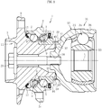
- a wheel bearing device 1 illustrated in FIG. 1 is a typical example of a structure capable of satisfying such needs.
- This wheel bearing device 1 is formed into a unit, and is constructed so as to be removably mounted to a constant velocity universal joint 31.
- the wheel bearing device 1 mainly includes an outer member 2, a hub wheel 3, an inner ring 4, balls 5 as rolling elements, and a retainer 6. Double-row outer raceway surfaces 7, 7 are formed on an inner periphery of the outer member 2, and a vehicle body mounting flange 2a configured to be mounted to a knuckle (not shown) of a vehicle body is integrally formed on an outer periphery of the outer member 2.
- a wheel mounting flange 8 configured to mount a wheel (not shown) is integrally formed at one end of the hub wheel 3.
- An inner raceway surface 9 opposing to one of the double-row outer raceway surfaces 7, 7 of the outer member 2 and a small-diameter step portion 10 having a cylindrical shape extending in the axial direction from the inner raceway surface 9 are formed on an outer periphery of the hub wheel 3.
- the inner ring 4 is press-fitted to the small-diameter step portion 10, and an inner raceway surface 9 opposing to another one of the double-row outer raceway surfaces 7, 7 of the outer member 2 is formed on an outer periphery of the inner ring 4.
- the hub wheel 3 and the inner ring 4 construct an inner member 11.
- the plurality of balls 5, 5 are built so as to be rollable between the double-row outer raceway surfaces 7, 7 of the outer member 2 and the double-row inner raceway surfaces 9, 9 of the inner member 11, and the balls 5 are received in the retainer 6.
- the inner ring 4 is fixed in the axial direction by a staked portion 17 formed by plastically deforming an end portion of the small-diameter step portion 10 of the hub wheel 3 radially outward.
- a face spline 18 is formed on an end surface of the staked portion 17.
- the constant velocity universal joint 31 mainly includes an outer joint member 32, an inner joint member 33, a cage 34, and torque transmitting balls 35.
- the outer joint member 32 includes a cup portion 36 and a bottom portion 37 integrally formed with the cup portion 36, and a female thread portion 38 is formed on an inner periphery of the bottom portion 37.
- a face spline 40 is formed on a shoulder portion 39 of the bottom portion 37. The face spline 40 is brought into abutment in the axial direction against the face spline 18 formed on an end surface of the staked portion 17 of the hub wheel 3, resulting in a mutually meshed state. With this configuration, a rotation torque from the shaft (not shown) can be transmitted to the wheel mounting flange 8 through the constant velocity universal joint 31 and the hub wheel 3.
- the constant velocity universal joint 31 and the wheel bearing device 1 having the configurations described above are fastened and fixed to each other in the axial direction by, for example, treadedly engaging a fastening bolt 20 with the female thread 38 on the bottom portion 37 of the outer joint member 32.
- a pitch cone angle is given as one of inspection items after the manufacturing of the rotation power transmitting element of this type.
- the pitch cone angle refers to an apex angle ⁇ of a reference surface (pitch cone PC) having a conical shape acquired by overlapping pitch circles Pc1, Pc2, ... respectively passing through meshing positions Pe1, P2, ... between teeth 41constructing the one face spline 40 and teeth 19 constructing the another mating face spline 18 (see FIG. 4 described later) in a rotation axis direction of the face splines 18 and 40.
- the pitch cone angle ⁇ also affects strengths of the face splines 40 and 18, and it is important to evaluate the precisions thereof.
- Patent Literature 1 a method of using a gauge head of a contact-type probe is proposed as a method of measuring a tooth shape of a gear.
- Patent Literature 1 JP 2011-133237
- the pitch cone angle of the face spline can be acquired with use of the measurement technology described in Patent Literature 1.
- the contact-type probe needs to be used to scan a certain region on tooth surfaces, resulting in an increase in time required for the measurement work.
- a tester three-dimensional shape measurement device provided with the contact-type probe
- the existing measurement technology for example, the technology described in Patent Literature 1 is not suitable for total inspection for mass-produced articles, for example, inline measurement work.
- the above-mentionedproblema rises not only in the face spline, and is widely concerned in a general rotation power transmitting element that is formed by arranging a plurality of ridges in a circumferential direction, and is configured to enable transmission of rotation power through engagement with opposing ridges.
- a technical problem to be solved herein is to measure a pitch cone angle of a rotation power transmitting element such as a face spline in a simple manner and in a short period of time.
- a pitch cone angle measurement method of measuring a pitch cone angle of a rotation power transmitting element that is formed by arranging a plurality of ridges in a circumferential direction, and is configured to enable transmission of rotation power through engagement with opposing ridges
- the pitch cone angle measurement method comprising: a first abutment step of bringing an abutment portion having predetermined shape and dimension into abutment against the plurality of ridges; a second abutment step of bringing the abutment portion into abutment against the plurality of ridges at a position separated from a position at which the plurality of ridges and the abutment portion are brought into abutment against each other in the first abutment step in a direction orthogonal to a rotation axis direction of the rotation power transmitting element by a predetermined radial distance; a first abutment step of bringing an abutment portion having predetermined shape and dimension into abutment against the plurality of ridges; a second
- the pitch cone angle of the rotation power transmitting element can be acquired based on a trigonometric function by simply bringing the abutment portion having the predetermined shape and dimension into abutment against the ridges at the two locations separated from each other by the predetermined distance in the direction orthogonal to the rotation axis direction of the rotation power transmitting element, namely the radial direction (radial distance), and acquiring the distance in the rotation axis direction between the abutment positions at the two locations, namely, a relative height between the abutment positions against the ridges .
- the pitch cone angle of the rotation power transmitting element can be acquired in a very simple and easy manner .
- the abutment portion may be moved in the rotation axis direction to bring the abutment portion into abutment against the plurality of ridges in each of the first abutment step and the second abutment step.
- the ridges and the abutment portion are brought into abutment against each other at the two locations, and the distance in the rotation axis direction between the respective abutment positions is measured.
- the distance in the rotation axis direction can be acquired based on stroke amounts (movement amounts in the rotation axis direction) of the abutment portion at this time.
- the distance in the rotation axis direction can be acquired more precisely, and a calculation precision of the pitch cone angle calculated based on the distance in the rotation axis direction can thus be increased.
- the shape and the dimension of the abutment portion may be set so that the abutment portion is brought into abutment against the plurality of ridges at meshing positions between the plurality of ridges and the opposing ridges.
- the pitch cone angle of the rotation power transmitting element subject to the measurement of one embodiment of the present invention is the apex angle of the pitch cone acquired when the plurality of pitch circles of the rotation power transmitting element are overlapped in the rotation axis direction as described above, and the pitch circle is a virtual circle passing through the meshing positions between the ridges of the rotation power transmitting element with the opposing ridges (refer to FIG. 3A and FIG. 3B , and FIG. 4 described later) .
- the abutment points between the abutment portion and the ridges can be considered as being located at the meshing positions between the ridges and the opposing ridges.
- the distance in the rotation axis direction between the abutment positions of the abutment portion and the ridges acquired in the distance measurement step can directly be used for the calculation of the pitch cone angle.
- this can also increase the calculation precision of the pitch cone angle.
- the abutment portion may have a spherical shape.
- the ridges and the abutment portion can be brought into abutment against each other in point contact accurately at intended positions regardless of shapes (particularly a shape of a side surface) of the ridges.
- the abutment portion is formed into a spherical shape, even when the abutment portion is brought into abutment against the ridges at a position displaced from the intended position, the abutment portion itself can be guided to the predetermined position between the side surfaces (for example, tooth surfaces) of the ridges. Therefore, very stable abutment work and the subsequent distance measurement work can be performed.
- two abutment portions is used so that one of the abutment portions is elastically supported by a relative displacement measurement portion, and another one of the abutment portions is configured to be movable integrally with the relative displacement measurement portion.
- a movement distance in the rotational axis direction of the another abutment portion from a state in which the one abutment portion is held in abutment against the plurality of ridges to a state in which the another abutment portion is moved in the rotation axis direction to bring the another abutment portion into abutment against the ridge is measured by the relative displacement measurement portion as a relative displacement of the one abutment portion in the rotation axis direction.
- the relative distance in the rotation axis direction may be calculated based on the measured movement distance.
- the two abutment portions and the relative displacement measurement portion are provided, and are integrally moved in the rotation axis direction, one of the abutment portions is first brought into abutment against the ridges, and then, the another one of the abutment portions is continuously moved in the rotation axis direction to be brought into abutment against the ridges. Consequently, the relative distance in the rotation axis direction can automatically be calculated.
- the relative distance in the rotation axis direction can automatically be calculated during the approach operation and the abutment operation of the abutment portion with respect to the ridges without individually detecting the abutment positions between the respective abutment portions and the ridges.
- a mechanism configured to integrally move the two abutment portions and the relative displacement measurement portion is provided, a stable measurement precision can be provided regardless of proficiency of a worker.
- the above-mentioned pitch cone angle measurement method can suitably be applied to, for example, a case in which the rotation power transmitting element comprises a face spline.
- the above-mentioned pitch cone angle measurement method can suitably be applied to, for example, a case in which at least one of the rotation power transmitting element on which the plurality of ridges are formed and a mating rotation power transmitting element on which the opposing ridges are formed constructs a wheel bearing device.
- the above-mentioned pitch cone angle measurement method can suitably be applied to, for example, a case in which at least one of the rotation power transmitting element on which the plurality of ridges are formed and a mating rotation power transmitting element on which the opposing ridge is formed constructs a constant velocity universal joint.
- the above-mentioned pitch cone angle measurement method can suitably be applied to, for example, a case in which one of the rotation power transmitting element on which the plurality of ridges are formed and a mating rotation power transmitting element on which the opposing ridges are formed constructs a wheel bearing device, and another one of the rotation power transmitting element and the mating rotation power transmitting element constructs a constant velocity universal joint.
- a pitch cone angle measurement device which is configured to measure a pitch cone angle of a rotation power transmitting element that is formed by arranging a plurality of ridges in a circumferential direction, and is configured to engage with an opposing ridge, thereby enabling transmission of rotation power
- the pitch cone angle measurement device comprising: a first abutment portion that has predetermined shape and dimension, and is capable of being brought into abutment against the plurality of ridges; a second abutment portion that has predetermined shape and dimension, and is capable of being brought into abutment against the plurality of ridges at a position separated from a position at which the plurality of ridges and the first abutment portion are brought into abutment against each other in a direction orthogonal to a rotation axis direction of the rotation power transmitting element by a predetermined
- the pitch cone angle of the rotation power transmitting element can be acquired based on a trigonometric function simply by bringing the abutment portion having the predetermined shape and dimension into abutment against the ridges at the two locations separated from each other by the predetermined distance in the direction orthogonal to the rotation axis direction of the rotation power transmitting element, namely the radial direction (radial distance), and acquiring the distance in the rotation axis direction between the abutment positions at the two locations, namely, a relative height between the abutment positions against the ridges.
- the pitch cone angle of the rotation power transmitting element can be acquired in a very simple and easy manner. Moreover, it is sufficient to perform the simple work of measuring the distance in the rotation axis direction between the abutment positions between the abutment portion and the ridges when the abutment portion having the predetermined shapes and the dimensions is brought into abutment against the ridges at the two locations is sufficient, and hence time required for work is shortened. Moreover, when only the above-mentioned operations and work are sufficient, a required facility is simplified, thereby being capable of reducing a work cost.
- the present invention it is possible to measure the pitch cone angle of the rotation power transmitting element such as the face spline in a simple manner and in a short period of time.
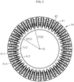
- FIG. 4 is a view (plan view) for illustrating a face spline 40 formed on a bottom portion 37 of a constant velocity universal joint 31 illustrated in FIG. 1 as viewed in a direction along a rotation axis (in this case, a rotation axis L of an outer joint member 32).
- the face spline 40 is formed by arranging a plurality of teeth 41 being ridges in a circumferential direction.
- the face spline 40 has a shape symmetrical about its rotation axis L.
- each of the teeth 41 extends in a radial direction of the face spline 40 (consequently the outer joint member 32), and a cross-sectional shape of each of the teeth 41 is the same on any cross section in the radial direction.
- a distance between the teeth 41 adjacent to each other in the circumferential direction namely a dimension of a tooth bottom 42 in the circumferential direction
- an outer diameter dimension of the face spline 40 in a case of being used for a passenger vehicle including a four-wheel drive vehicle is approximately from ⁇ 45 mm to ⁇ 70 mm.
- the module of the teeth 41 is approximately from 1 mm to 3 mm.
- the pressure angle is approximately in a range from 20° to 30°.
- a face spline 18 provided on a side of the wheel bearing device 1 also has the same shapes and specifications.
- the face splines 18 and 40 can be formed by various methods. Although not illustrated, for example, the face spline 40 provided on the side of the constant velocity universal joint 31 can be formed on a shoulder portion 39 of the bottom portion 37 simultaneously when the outer joint member 32 is formed by plastic working. As a matter of course, after the outer joint member 32 is manufactured, the face spline 40 may be formed by plastic working on the shoulder portion 39 of the bottom portion 37. Alternatively, the face spline 40 may be formed by appropriate methods other than the plastic working (for example, cutting work through NC control).
- the face spline 18 provided on the side of the wheel bearing device 1 may be formed simultaneously with a staked portion 17 with use of an orbital forming machine in a rotary mode (not shown).
- the forming method for the face spline 18 is not limited to the swinging forming in the rotary mode, and the face spline 18 may be formed by other swinging forming, plastic working, or the like.
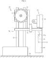
- FIG. 5 is a front view for illustrating an entire configuration of a pitch cone angle measurement device 50 according to the embodiment of the present invention
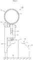
- FIG. 6 is a side view for illustrating the pitch cone angle measurement device 50.
- the pitch cone angle measurement device 50 comprises a first abutment portion 51, a second abutment portion 52, a distance measurement portion 53, and a lift mechanism 54.
- the first abutment portion 51 is capable of being brought into abutment against the teeth 41 of the face spline 40 being ridges.
- the second abutment portion 52 is provided independently of the first abutment portion 51, and is capable of being brought into abutment against the teeth 41 of the face spline 40.
- the lift mechanism 54 is configured to integrally lift up and down the first and second abutment portions 51 and 52 and the distance measurement portion 53.
- the first abutment portion 51 can have any suitable shape and dimension as long as the first abutment portion 51 can be brought into abutment against tooth surfaces 41a of the teeth 41 of the face spline 40 on the constant velocity universal joint 31 side.
- the first abutment portion 51 has, for example, a spherical shape.
- an outer diameter dimension of the first abutment portion 51 is set so that the first abutment portion 51 is brought into abutment against the tooth surfaces 41a of the teeth 41 at meshing positions Pe1 between the teeth 41 of the face spline 40 subject to the measurement and the tooth 19 of the opposing face spline 18.
- the second abutment portion 52 is arranged at a position separated from the first abutment portion 51 by a predetermined distance in a direction orthogonal to its movement direction. Specifically, as illustrated in FIG. 8 , the second abutment portion 52 is arranged so that a center axis C2 is positioned at a position separated from a center axis C1 of the first abutment portion 51 in the direction orthogonal to the direction along the rotation axis L of the constant velocity universal joint 31 (right-and-left direction of FIG. 8 ) by a predetermined radial distance d.
- the second abutment portion 52 can have any suitable shape and dimension as long as the second abutment portion 52 can be brought into abutment against the tooth surfaces 41a of the teeth 41 of the face spline 40 on the constant velocity universal joint 31 side.
- the second abutment portion 52 has, for example, a spherical shape.
- an outer diameter dimension of the second abutment portion 52 is set so that the second abutment portion 52 is brought into abutment against the tooth surfaces 41a of the teeth 41 at meshing positions Pe2 between the teeth 41 of the face spline 40 subject to the measurement and the tooth 19 of the opposing face spline 18.
- an outer diameter dimension of the second abutment portion 52 is set so as to be the same size as the outer diameter dimension of the first abutment portion 51.
- the distance measurement portion 53 is configured to enable measurement of a relative movement distance in the rotation axis L direction of the second abutment portion 52 from the state in which the first abutment portion 51 is held in abutment against the tooth surfaces 41a of the teeth 41.
- the distance measurement portion 53 is constructed by, for example, a dial gauge 55 being a relative displacement measurement portion, and is configured to bring a gauge head 55a into abutment against a movable pin 56 coupled to the first abutment portion 51, thereby being capable of elastically supporting the first abutment portion 51 coupled to the movable pin 56.
- the lift mechanism 54 comprises support columns 57, a sliding portion 58 mounted to the support columns 57 so as to be slidable, and a lift feeder handle 59 configured to apply a driving force to the sliding portion 58, and, for example, a height gauge may be used as the lift mechanism 54.
- the support columns 57 of the lift mechanism 54 are provided in parallel with the rotation axis L of the face spline 40 subject to the measurement ( FIG. 7 ), and the first abutment portion 51, the second abutment portion 52, and the distance measurement portion 53 are integrally provided on the sliding portion 58.
- the first and second abutment portions 51 and 52 integrally provided on the sliding portion 58 are configured to be lifted up and down along the rotation axis L of the constant velocity universal joint 31 ( FIG. 7 ).
- a positioning portion 60 is provided in the vicinity of the first and second abutment portions 51 and 52.
- the positioning portion 60 is coupled and fixed to the sliding portion 58 through, for example, a coupling portion 61 extending in a horizontal direction, and, as illustrated in FIG. 7 , is configured to enable positioning of the outer joint member 32 so that the first and second abutment portions 51 and 52 can respectively be brought into abutment against the tooth surfaces 41a at the radial predetermined positions of the common teeth 41 under a state in which the positioning portion 60 is held in abutment against an outer peripheral surface of the outer joint member 32 on which the face spline 40 subject to the measurement is formed.
- Reference numeral 62 denotes a surface plate (refer to FIG. 5 to FIG. 7 ).
- the outer joint member 32 (or the constant velocity universal joint 31 including the outer j oint member 32) on which the face spline 40 subject to the measurement is formed is brought into abutment against the positioning portion 60 of the pitch cone angle measurement device 50.
- the outer peripheral surface of the outer joint member 32 is brought into abutment against the positioning portion 61 so that the rotation axis L of the face spline 40 is parallel with the lift direction of the sliding portion 58, thereby bringing about a state in which the face spline 40 is positioned to have a predetermined posture at a predetermined position.
- the lift feeder handle 59 of the lift mechanism 54 is driven to lift down the sliding portion 58, thereby bringing the first abutment portion 51 integrally provided on the sliding portion 58 into abutment against the tooth surfaces 41a of the face spline 40 ( FIG. 8 and FIG. 9A ).
- the first abutment portion 51 is brought into abutment against the tooth surfaces 41a, 41a adjacent to each other in the circumferential direction at the meshing positions Pe1 between the teeth 41 of the face spline 40 subject to the measurement and the opposing tooth 19.
- a dial reading (relative position of the first abutment portion 51) of the dial gauge 55 constructing the distance measurement portion 53 is set to zero.
- the second abutment portion 52 is not brought into abutment against the tooth surfaces 41a yet ( FIG. 8 and FIG. 9B ) .
- the sliding portion 58 of the lift mechanism 54 is further lifted down from the state in which the first abutment portion 51 is held in abutment against the tooth surfaces 41a in such a manner, and the second abutment portion 52 integrally provided on the sliding portion 58 is brought into abutment against the tooth surfaces 41a of the face spline 40 ( FIG. 10 and FIG. 11B ).
- the second abutment portion 52 is brought into abut against the tooth surfaces 41a common to the tooth surfaces 41a against which the first abutment portion 51 held in abutment ( FIG. 10 ), and is simultaneously brought into abutment against the tooth surfaces 41a, 41a adjacent to each other in the circumferential direction at the meshing positions Pe2 with the opposing tooth 19 ( FIG. 11B ).
- a lift down amount of the second abutment portion 52 from the state in which the first abutment portion 51 is held in abutment against the tooth surfaces 41a to the state in which the second abutment portion 52 is held in abutment against the tooth surfaces 41a corresponds to a relative displacement of the dial gauge 55 ( FIG. 7 ).
- the above-mentioned relative displacement of the dial gauge 55 is equal to a value acquired by subtracting a separation distance S between the center positions O1 and O2 when the first and second abutment portions 51 and 52 are brought into abutment against the tooth surfaces 41a from an initial separation distance S0 between the center positions O1 and O2 of both of the abutment portions 51 and 52 (refer to FIG. 6 ).
- this separation distance S may be considered to be equal to a difference PCD1-PCD2 between pitch circle radii PCD1 and PCD2 (refer to FIG. 8 and the like) at the respective meshing positions Pe1 and Pe2.
- a value acquired by subtracting (an absolute value of) a value, which is acquired by subtracting the dial reading of the dial gauge 55 in the state in which the first abutment portion 51 is held in abutment against the tooth surfaces 41a from the dial reading of the dial gauge 55 in the state in which the second abutment portion 52 is held in abutment against the tooth surfaces 41a, from the initial separation distance S0 is measured as the separation distance S.
- the dial reading of the dial gauge 55 is set to zero when the first abutment portion 51 is held in abutment against the tooth surfaces 41a, and a value acquired by subtracting (an absolute value of) the dial reading of the dial gauge 55 in the state in which the second abutment portion 52 is held in abutment against the tooth surfaces 41a from the initial separation distance S0 is thus the separation distance S.
- the pitch cone angle ⁇ of the face spline 40 is calculated based on the separation distance S acquired in Step S4 and the radial distance d.
- the following equation 1 holds true for a relationship between the separation distance S in a vertical direction between the center positions O1 and O2 of the first and second abutment portions 51 and 52 and the radial distance d.
- an angle ⁇ is an angle of an intersection between a line connecting between the center positions O1 and O2 of the first and second abutment portions 51 and 52 and a line orthogonal to the rotation axis L
- the following equation 2 holds true for a relationship between the angle ⁇ and the pitch cone angle ⁇ subject to the calculation.
- the pitch cone angle ⁇ can be acquired as the following equation 3, which is a function of the separation distance S in the vertical direction between the center positions O1 and O2 and the radial distance d, based on the equations 1 and 2.
- ⁇ ⁇ ⁇ A r c tan S d
- the pitch cone angle ⁇ of the face spline 40 can be acquired based on the trigonometric function by simply bringing the abutment portions 51 and 52 having the predetermined shape and the dimension into abutment against the tooth surfaces 41a at the two locations separated by the predetermined distance (radial distance d) in the direction orthogonal to the rotation axis L direction of the face spline 40, in other words, in the radial direction of the face spline 40, and acquiring the separation distance S in the rotation axis L direction between the abutment positions Pe1 and Pe2 at the two locations in this case.
- the pitch cone angle ⁇ of the face spline 40 can be acquired in a very simple and easy manner. Moreover, it is sufficient to perform the simple work of measuring the separation distance S in the rotation axis L direction between the abutment positions Pe1 and Pe2 of the abutment portions 51 and 52 and the tooth surfaces 41a when the abutment portions 51 and 52 having the predetermined shape and dimension are brought into abutment against the tooth surfaces 41a at the two locations, and hence time required for work can be shortened. Moreover, when only the above-mentioned operations and work are sufficient, a required facility is simplified, thereby being capable of reducing in a work cost.
- the first abutment portion 51 is elastically supported by the dial gauge 55 being the distance measurement portion 53, and the lift down amount of the second abutment portion 52 from the state in which the first abutment portion 51 is held in abutment against the tooth surfaces 41a to the state in which the second abutment portion 52 is held in abutment against the tooth surfaces 41a is acquired as the dial reading variation of the dial gauge 55 (relative displacement of the first abutment portion 51 with respect to the dial gauge 55) .
- the separation distance S and, consequently, the pitch cone angle ⁇ can thus automatically be acquired by the simple work of lifting down the first and second abutment portions 51 and 52, and sequentially bringing the first and second abutment portions 51 and 52 into abutment against the common tooth surfaces 41a.
- the pitch cone angle ⁇ can more simply be acquired.
- a stable measurement precision can be acquired regardless of proficiency of a worker by providing the mechanism (lift mechanism 54) configured to integrally move the first and second abutment portions 51 and 52 and the distance measurement portion 53.
- the pitch cone angle measurement method and the measurement device 50 may take other forms as long as the forms are within the scope of the present invention.
- first and second abutment portions 51 and 52 are set so that the respective abutment portions 51 and 52 are brought into abutment against the tooth surfaces 41a of the teeth 41 at the meshing positions Pe1 between the teeth 41 of the face spline 40 subject to the measurement and the tooth 19 of the opposing face spline 18.
- the first and second abutment portions 51 and 52 may be set to have shape and dimension other than such shape and dimension.
- the abutment positions between the tooth surfaces 41a and the respective abutment portions 51 and 52 are acquired based on the preset shapes and dimensions of the respective abutment portions 51 and 52, separation distances in the rotation axis L direction between the respective abutment positions and the meshing positions Pe1 and Pe2 are respectively calculated, and those calculated separation distances are acquired as correction values.
- the pitch cone angle ⁇ can precisely be calculated in consideration of actual displacements in a height direction respectively between the abutment positions against the tooth surfaces 41a and the meshing positions Pe1 and Pe2 with the tooth surfaces 41a.
- the separation distance S may be calculated by a method other than this.
- the separation distance S in the rotation axis L direction from the position at which the first abutment portion 51 is held in abutment against the tooth surfaces 41a to the position at which the second abutment portion 52 is held in abutment against the tooth surfaces 41a may be calculated by providing a position detector that is capable of detecting the positions in the slide direction of the respective abutment portions 51 and 52.
- an abutment detection portion configured to detect the abutment of the respective abutment portions 51 and 52 against the tooth surfaces 41a may be provided to acquire positions in the rotation axis L direction when the abutment is detected, thereby calculating the separation distance S in the rotation axis L direction.
- a model block 63 comprising a first flat surface 64 and a second flat surface 65 may be used in advance to calibrate the distance measurement portion 53 (dial gauge 55), thereby simplifying the relative distance measurement step S4 and the pitch cone angle calculation step S5.
- a step between the first flat surface 64 and the second flat surface 65 parallel with each other of the model block 63 is set to an intended dimension of the separation distance S between the center positions O1 and O2 of the first and second abutment portions 51 and 52.
- the first abutment portion 51 is brought into abutment against the first flat surface 64, and, then, the second abutment portion 52 is brought into abutment against the second flat surface 65 under a state in which the model block 63 is held in abutment against the positioning portion 60 ( FIG. 12 ). Then, the dial of the dial gauge 55 is set to zero in this state.
- the dial of the dial gauge 55 When the dial of the dial gauge 55 is once set to zero in such a manner, it is then possible to instantaneously determine whether or not the pitch cone angle ⁇ of the face spline 40 is within an allowable range by simply actually and sequentially bringing the first and second abutment portions 51 and 52 into abutment against the tooth surfaces 41a of the face spline 40 subject to the measurement, and reading the dial of the dial gauge 55 in this case (specifically a variation from zero toward a plus or minus direction) (a permissible variation from the intended dimension of the separation distance S is calculated in advance through inverse calculation from the separation distances S at an upper limit and a lower limit of the pitch cone angle ⁇ ).
- the measurement method and the measurement device 50 according to the present invention may also be applied to a rotation power transmitting element other than the face spline 40.
- the present invention may be applied to a rotation power transmitting element which is suitably constructed as long as the element has a pitch cone angle and is formed by arranging a plurality of ridges in the circumferential direction.
Landscapes
- Engineering & Computer Science (AREA)
- General Engineering & Computer Science (AREA)
- Physics & Mathematics (AREA)
- General Physics & Mathematics (AREA)
- Mechanical Engineering (AREA)
- A Measuring Device Byusing Mechanical Method (AREA)
Abstract
Description
- The present invention relates to a pitch cone angle measurement method and a pitch cone angle measurement device for a rotation power transmitting element such as a face spline.
- For example, a power transmission device configured to transmit engine power of an automobile and the like to a wheel needs to transmit the power from an engine to the wheel, and simultaneously allow an angular displacement and an axial displacement due to bouncing of the vehicle during travel as well as an angular displacement for a turn of the vehicle. Therefore, in general, a driveshaft of an automobile and the like has the following structure. A plunging type constant velocity universal joint that can adapt to the angular displacement and the axial displacement is arranged on a differential gear side (inboard side), and a fixed type constant velocity universal joint that can form a large operating angle is arranged on a drive wheel side (outboard side) . Both of the constant velocity universal joints are coupled to each other through intermediation of the shaft. Moreover, the constant velocity universal joint on the drive wheel side (fixed type constant velocity universal joint) is coupled to a wheel bearing device configured to rotationally support the drive wheel.
- Incidentally, a need for improvement in fuel economy of the automobile has been increasing in recent years, and a decrease in weight of the wheel bearing device, which is one of automobile components, is highly demanded. Hitherto, various proposals have been made to decrease the weight of the wheel bearing device, and, simultaneously, simplification in assembly and disassembly to decrease a work cost is also strongly needed in an assembly site and a repair market of the automobile.
- A wheel bearing
device 1 illustrated inFIG. 1 is a typical example of a structure capable of satisfying such needs. This wheel bearingdevice 1 is formed into a unit, and is constructed so as to be removably mounted to a constant velocityuniversal joint 31. In this case, the wheel bearingdevice 1 mainly includes anouter member 2, ahub wheel 3, aninner ring 4,balls 5 as rolling elements, and aretainer 6. Double-rowouter raceway surfaces outer member 2, and a vehiclebody mounting flange 2a configured to be mounted to a knuckle (not shown) of a vehicle body is integrally formed on an outer periphery of theouter member 2. Awheel mounting flange 8 configured to mount a wheel (not shown) is integrally formed at one end of thehub wheel 3. Aninner raceway surface 9 opposing to one of the double-rowouter raceway surfaces outer member 2 and a small-diameter step portion 10 having a cylindrical shape extending in the axial direction from theinner raceway surface 9 are formed on an outer periphery of thehub wheel 3. Theinner ring 4 is press-fitted to the small-diameter step portion 10, and aninner raceway surface 9 opposing to another one of the double-rowouter raceway surfaces outer member 2 is formed on an outer periphery of theinner ring 4. Moreover, thehub wheel 3 and theinner ring 4 construct aninner member 11. The plurality ofballs outer raceway surfaces outer member 2 and the double-rowinner raceway surfaces inner member 11, and theballs 5 are received in theretainer 6. Theinner ring 4 is fixed in the axial direction by a stakedportion 17 formed by plastically deforming an end portion of the small-diameter step portion 10 of thehub wheel 3 radially outward. In this case, aface spline 18 is formed on an end surface of the stakedportion 17. - The constant velocity
universal joint 31 mainly includes anouter joint member 32, aninner joint member 33, acage 34, andtorque transmitting balls 35. Theouter joint member 32 includes acup portion 36 and abottom portion 37 integrally formed with thecup portion 36, and afemale thread portion 38 is formed on an inner periphery of thebottom portion 37. In this case, aface spline 40 is formed on ashoulder portion 39 of thebottom portion 37. Theface spline 40 is brought into abutment in the axial direction against theface spline 18 formed on an end surface of the stakedportion 17 of thehub wheel 3, resulting in a mutually meshed state. With this configuration, a rotation torque from the shaft (not shown) can be transmitted to thewheel mounting flange 8 through the constant velocityuniversal joint 31 and thehub wheel 3. - The constant velocity
universal joint 31 and the wheel bearingdevice 1 having the configurations described above are fastened and fixed to each other in the axial direction by, for example, treadedly engaging a fasteningbolt 20 with thefemale thread 38 on thebottom portion 37 of theouter joint member 32. With such a configuration of the unit which is removably mounted, the weight and size can be reduced, and the disassembly and assembly work can be simplified. - Incidentally, a pitch cone angle is given as one of inspection items after the manufacturing of the rotation power transmitting element of this type. As illustrated in
FIG. 2, FIG. 3A, and FIG. 3B , the pitch cone angle refers to an apex angle θ of a reference surface (pitch cone PC) having a conical shape acquired by overlapping pitch circles Pc1, Pc2, ... respectively passing through meshing positions Pe1, P2, ... between teeth 41constructing the oneface spline 40 andteeth 19 constructing the another mating face spline 18 (seeFIG. 4 described later) in a rotation axis direction of theface splines face splines - For example, in
Patent Literature 1, a method of using a gauge head of a contact-type probe is proposed as a method of measuring a tooth shape of a gear. - Patent Literature 1:
JP 2011-133237 - For example, the pitch cone angle of the face spline can be acquired with use of the measurement technology described in
Patent Literature 1. However, in such a case, the contact-type probe needs to be used to scan a certain region on tooth surfaces, resulting in an increase in time required for the measurement work. Moreover, a tester (three-dimensional shape measurement device provided with the contact-type probe) according to the above-mentioned measurement technology is very expensive. For the above-mentioned reason, the existing measurement technology, for example, the technology described inPatent Literature 1 is not suitable for total inspection for mass-produced articles, for example, inline measurement work. - As a matter of course, the above-mentionedproblemarises not only in the face spline, and is widely concerned in a general rotation power transmitting element that is formed by arranging a plurality of ridges in a circumferential direction, and is configured to enable transmission of rotation power through engagement with opposing ridges.
- In view of the above-mentioned circumstances, a technical problem to be solved herein is to measure a pitch cone angle of a rotation power transmitting element such as a face spline in a simple manner and in a short period of time.
- The above-mentioned problem is solved by a pitch cone angle measurement method according to the present invention. That is, according to a feature of the measurement method, there is provided a pitch cone angle measurement method of measuring a pitch cone angle of a rotation power transmitting element that is formed by arranging a plurality of ridges in a circumferential direction, and is configured to enable transmission of rotation power through engagement with opposing ridges, the pitch cone angle measurement method comprising: a first abutment step of bringing an abutment portion having predetermined shape and dimension into abutment against the plurality of ridges; a second abutment step of bringing the abutment portion into abutment against the plurality of ridges at a position separated from a position at which the plurality of ridges and the abutment portion are brought into abutment against each other in the first abutment step in a direction orthogonal to a rotation axis direction of the rotation power transmitting element by a predetermined radial distance; a distance measurement step of measuring a distance in the rotation axis direction between the position at which the plurality of ridges are brought into abutment against the abutment portion in the first abutment step and the position at which the plurality of ridges are brought into abutment against the abutment portion in the second abutment step; and a pitch cone angle calculation step of calculating a pitch cone angle of the rotation power transmitting element based on the measured distance in the rotation axis direction and the predetermined radial distance.
- With the measurement method according to one embodiment of the present invention, the pitch cone angle of the rotation power transmitting element can be acquired based on a trigonometric function by simply bringing the abutment portion having the predetermined shape and dimension into abutment against the ridges at the two locations separated from each other by the predetermined distance in the direction orthogonal to the rotation axis direction of the rotation power transmitting element, namely the radial direction (radial distance), and acquiring the distance in the rotation axis direction between the abutment positions at the two locations, namely, a relative height between the abutment positions against the ridges . Thus, the pitch cone angle of the rotation power transmitting element can be acquired in a very simple and easy manner . Moreover, it is sufficient to perform the simple work of measuring the distance in the rotation axis direction between the abutment positions of the abutment portion and the ridges when the abutment portion having the predetermined shape and dimension is brought into abutment against the ridges at the two locations, and hence time required for work is shortened. Moreover, when only the above-mentioned operations and work are sufficient, a required facility is simplified, thereby being capable of reducing a work cost.
- Further, in the pitch cone angle measurement method according to one embodiment of the present invention, the abutment portion may be moved in the rotation axis direction to bring the abutment portion into abutment against the plurality of ridges in each of the first abutment step and the second abutment step.
- In one embodiment of the present invention, as described above, the ridges and the abutment portion are brought into abutment against each other at the two locations, and the distance in the rotation axis direction between the respective abutment positions is measured. Thus, when the abutment portion is moved in the rotation axis direction to bring the abutment portion into abutment against the ridges in each of the abutment steps, the distance in the rotation axis direction can be acquired based on stroke amounts (movement amounts in the rotation axis direction) of the abutment portion at this time. As a result, the distance in the rotation axis direction can be acquired more precisely, and a calculation precision of the pitch cone angle calculated based on the distance in the rotation axis direction can thus be increased.
- Further, in the pitch cone angle measurement method according to one embodiment of the present invention, the shape and the dimension of the abutment portion may be set so that the abutment portion is brought into abutment against the plurality of ridges at meshing positions between the plurality of ridges and the opposing ridges.
- The pitch cone angle of the rotation power transmitting element subject to the measurement of one embodiment of the present invention is the apex angle of the pitch cone acquired when the plurality of pitch circles of the rotation power transmitting element are overlapped in the rotation axis direction as described above, and the pitch circle is a virtual circle passing through the meshing positions between the ridges of the rotation power transmitting element with the opposing ridges (refer to
FIG. 3A and FIG. 3B , andFIG. 4 described later) . Thus, when the shape and the dimension of the abutment portion are set so that the abutment portion is brought into abutment against the ridges at the meshing positions between the ridges and the opposing ridges, the abutment points between the abutment portion and the ridges can be considered as being located at the meshing positions between the ridges and the opposing ridges. Thus, in this case, the distance in the rotation axis direction between the abutment positions of the abutment portion and the ridges acquired in the distance measurement step can directly be used for the calculation of the pitch cone angle. In other words, the pitch cone angle can directly be calculated as (distance in rotation axis direction)/(predetermined radial distance)=tan{90°-(half of pitch cone angle)} without correction of the measured value or the like (refer toFIG. 10 described later) . Thus, this can also increase the calculation precision of the pitch cone angle. - Further, in the pitch cone angle measurement method according to one embodiment of the present invention, the abutment portion may have a spherical shape.
- When the abutment portion is formed into the spherical shape as described above, the ridges and the abutment portion can be brought into abutment against each other in point contact accurately at intended positions regardless of shapes (particularly a shape of a side surface) of the ridges. Moreover, when the abutment portion is formed into a spherical shape, even when the abutment portion is brought into abutment against the ridges at a position displaced from the intended position, the abutment portion itself can be guided to the predetermined position between the side surfaces (for example, tooth surfaces) of the ridges. Therefore, very stable abutment work and the subsequent distance measurement work can be performed.
- Further, in the pitch cone angle measurement method according to one embodiment of the present invention, two abutment portions is used so that one of the abutment portions is elastically supported by a relative displacement measurement portion, and another one of the abutment portions is configured to be movable integrally with the relative displacement measurement portion. A movement distance in the rotational axis direction of the another abutment portion from a state in which the one abutment portion is held in abutment against the plurality of ridges to a state in which the another abutment portion is moved in the rotation axis direction to bring the another abutment portion into abutment against the ridge is measured by the relative displacement measurement portion as a relative displacement of the one abutment portion in the rotation axis direction. The relative distance in the rotation axis direction may be calculated based on the measured movement distance.
- As described above, when the two abutment portions and the relative displacement measurement portion are provided, and are integrally moved in the rotation axis direction, one of the abutment portions is first brought into abutment against the ridges, and then, the another one of the abutment portions is continuously moved in the rotation axis direction to be brought into abutment against the ridges. Consequently, the relative distance in the rotation axis direction can automatically be calculated. Thus, the relative distance in the rotation axis direction can automatically be calculated during the approach operation and the abutment operation of the abutment portion with respect to the ridges without individually detecting the abutment positions between the respective abutment portions and the ridges. Moreover, when a mechanism configured to integrally move the two abutment portions and the relative displacement measurement portion is provided, a stable measurement precision can be provided regardless of proficiency of a worker.
- The above-mentioned pitch cone angle measurement method can suitably be applied to, for example, a case in which the rotation power transmitting element comprises a face spline.
- Further, the above-mentioned pitch cone angle measurement method can suitably be applied to, for example, a case in which at least one of the rotation power transmitting element on which the plurality of ridges are formed and a mating rotation power transmitting element on which the opposing ridges are formed constructs a wheel bearing device.
- Alternatively, the above-mentioned pitch cone angle measurement method can suitably be applied to, for example, a case in which at least one of the rotation power transmitting element on which the plurality of ridges are formed and a mating rotation power transmitting element on which the opposing ridge is formed constructs a constant velocity universal joint.
- Alternatively, the above-mentioned pitch cone angle measurement method can suitably be applied to, for example, a case in which one of the rotation power transmitting element on which the plurality of ridges are formed and a mating rotation power transmitting element on which the opposing ridges are formed constructs a wheel bearing device, and another one of the rotation power transmitting element and the mating rotation power transmitting element constructs a constant velocity universal joint.
- Further, the above-mentioned problem is solved also by a pitch cone angle measurement device according to the present invention. That is, according to a feature of the measurement device, there is provided a pitch cone angle measurement device which is configured to measure a pitch cone angle of a rotation power transmitting element that is formed by arranging a plurality of ridges in a circumferential direction, and is configured to engage with an opposing ridge, thereby enabling transmission of rotation power, the pitch cone angle measurement device comprising: a first abutment portion that has predetermined shape and dimension, and is capable of being brought into abutment against the plurality of ridges; a second abutment portion that has predetermined shape and dimension, and is capable of being brought into abutment against the plurality of ridges at a position separated from a position at which the plurality of ridges and the first abutment portion are brought into abutment against each other in a direction orthogonal to a rotation axis direction of the rotation power transmitting element by a predetermined radial distance; and a distance measurement portion that is configured to measure a distance in the rotation axis direction between the position at which the first abutment portion is brought into abutment against the plurality of ridges and the position at which the second abutment portion is brought into abutment against the plurality of ridges.
- Similarly to the measurement method according to one embodiment of the present invention, with the measurement method according to one embodiment of the present invention, the pitch cone angle of the rotation power transmitting element can be acquired based on a trigonometric function simply by bringing the abutment portion having the predetermined shape and dimension into abutment against the ridges at the two locations separated from each other by the predetermined distance in the direction orthogonal to the rotation axis direction of the rotation power transmitting element, namely the radial direction (radial distance), and acquiring the distance in the rotation axis direction between the abutment positions at the two locations, namely, a relative height between the abutment positions against the ridges. Thus, the pitch cone angle of the rotation power transmitting element can be acquired in a very simple and easy manner. Moreover, it is sufficient to perform the simple work of measuring the distance in the rotation axis direction between the abutment positions between the abutment portion and the ridges when the abutment portion having the predetermined shapes and the dimensions is brought into abutment against the ridges at the two locations is sufficient, and hence time required for work is shortened. Moreover, when only the above-mentioned operations and work are sufficient, a required facility is simplified, thereby being capable of reducing a work cost.
- As described above, according to the present invention, it is possible to measure the pitch cone angle of the rotation power transmitting element such as the face spline in a simple manner and in a short period of time.
-
-
FIG. 1 is a cross-sectional view for illustrating a wheel bearing device and a constant velocity universal joint according to an embodiment of the present invention. -
FIG. 2 is a cross-sectional view of a principal part for illustrating a pitch cone angle in the rotation power transmitting element. -
FIG. 3A is a cross-sectional view taken along the line A-A ofFIG. 2 , for illustrating the rotation power transmitting element illustrated inFIG. 2 . -
FIG. 3B is a cross-sectional view taken along the line B-B ofFIG. 2 , for illustrating the rotation power transmitting element illustrated inFIG. 2 . -
FIG. 4 is a plan view for illustrating a face spline provided on a side of the constant velocity universal joint illustrated inFIG. 1 . -
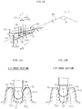
FIG. 5 is a side view for illustrating a pitch cone angle measurement device according to the one embodiment of the present invention. -
FIG. 6 is a front view for illustrating the pitch cone angle measurement device illustrated inFIG. 5 . -
FIG. 7 is a view for illustrating an example of a pitch cone angle measurement method with use of the measurement device illustrated inFIG. 5 , and is a front view for illustrating a state in which the face spline subject to the measurement is arranged at a predetermined position of the measurement device. -
FIG. 8 is a view for illustrating the example of the pitch cone angle measurement method with use of the measurement device illustrated inFIG. 5 , and is an enlarged cross-sectional view of a principal part for illustrating a state in which a first abutment portion is held in abutment against tooth surfaces of the face spline. -
FIG. 9A is a cross-sectional view taken along the line C-C ofFIG. 8 , for illustrating a position relationship between the first abutment portion and the tooth surfaces in the state illustrated inFIG. 8 . -
FIG. 9B is a cross-sectional view taken along the line D-D ofFIG. 8 , for illustrating a position relationship between a second abutment portion and the tooth surfaces in the state illustrated inFIG. 8 . -
FIG. 10 is a view for illustrating the example of the pitch cone angle measurement method with use of the measurement device illustrated inFIG. 5 , and is an enlarged cross-sectional view of a principal part for illustrating a state in which the second abutment portion is held in abutment against the tooth surfaces of the face spline. -
FIG. 11A is a cross-sectional view taken along the line E-E ofFIG. 10 , for illustrating a position relationship between the first abutment portion and the tooth surfaces in the state illustrated inFIG. 10 . -
FIG. 11B is a cross-sectional view taken along the line E-E ofFIG. 10 , for illustrating a position relationship between the second abutment portion and the tooth surfaces in the state illustrated inFIG. 10 . -
FIG. 12 is a view for illustrating an example of a calibration operation of a distance measurement portion with use of a model block, and is a front view for illustrating a state in which the model block is arranged at a predetermined position of the measurement device. - With reference to the drawings, description is made of an embodiment of the present invention.
-
FIG. 4 is a view (plan view) for illustrating aface spline 40 formed on abottom portion 37 of a constant velocity universal joint 31 illustrated inFIG. 1 as viewed in a direction along a rotation axis (in this case, a rotation axis L of an outer joint member 32). Theface spline 40 is formed by arranging a plurality ofteeth 41 being ridges in a circumferential direction. According to this embodiment, theface spline 40 has a shape symmetrical about its rotation axis L. Moreover, each of theteeth 41 extends in a radial direction of the face spline 40 (consequently the outer joint member 32), and a cross-sectional shape of each of theteeth 41 is the same on any cross section in the radial direction. A distance between theteeth 41 adjacent to each other in the circumferential direction (namely a dimension of a tooth bottom 42 in the circumferential direction) increases from the rotation axis L toward a radially outer side. As an example of specifications of theface spline 40, an outer diameter dimension of theface spline 40 in a case of being used for a passenger vehicle including a four-wheel drive vehicle is approximately from ϕ45 mm to ϕ70 mm. The module of theteeth 41 is approximately from 1 mm to 3 mm. The pressure angle is approximately in a range from 20° to 30°. Aface spline 18 provided on a side of thewheel bearing device 1 also has the same shapes and specifications. - The face splines 18 and 40 can be formed by various methods. Although not illustrated, for example, the
face spline 40 provided on the side of the constant velocity universal joint 31 can be formed on ashoulder portion 39 of thebottom portion 37 simultaneously when the outerjoint member 32 is formed by plastic working. As a matter of course, after the outerjoint member 32 is manufactured, theface spline 40 may be formed by plastic working on theshoulder portion 39 of thebottom portion 37. Alternatively, theface spline 40 may be formed by appropriate methods other than the plastic working (for example, cutting work through NC control). - Moreover, for example, the
face spline 18 provided on the side of thewheel bearing device 1 may be formed simultaneously with a stakedportion 17 with use of an orbital forming machine in a rotary mode (not shown). As a matter of course, the forming method for theface spline 18 is not limited to the swinging forming in the rotary mode, and theface spline 18 may be formed by other swinging forming, plastic working, or the like. - Next, with reference to
FIG. 5 to FIG. 11B , description is made of an example of a pitch cone angle measurement method for the face splines 18 and 40. In this embodiment, description is made of a case in which the pitch cone angle of theface spline 40 provided on the side of the constant velocity universal joint 31 out of the face splines 18 and 40 is measured as an example. -
FIG. 5 is a front view for illustrating an entire configuration of a pitch coneangle measurement device 50 according to the embodiment of the present invention, andFIG. 6 is a side view for illustrating the pitch coneangle measurement device 50. As illustrated inFIG. 5 andFIG. 6 , the pitch coneangle measurement device 50 comprises afirst abutment portion 51, asecond abutment portion 52, adistance measurement portion 53, and alift mechanism 54. Thefirst abutment portion 51 is capable of being brought into abutment against theteeth 41 of theface spline 40 being ridges. Thesecond abutment portion 52 is provided independently of thefirst abutment portion 51, and is capable of being brought into abutment against theteeth 41 of theface spline 40. Thelift mechanism 54 is configured to integrally lift up and down the first andsecond abutment portions distance measurement portion 53. - The
first abutment portion 51 can have any suitable shape and dimension as long as thefirst abutment portion 51 can be brought into abutment againsttooth surfaces 41a of theteeth 41 of theface spline 40 on the constant velocity universal joint 31 side. In this embodiment, thefirst abutment portion 51 has, for example, a spherical shape. Moreover, in this case, as illustrated in, for example,FIG. 9A described later and the like, an outer diameter dimension of thefirst abutment portion 51 is set so that thefirst abutment portion 51 is brought into abutment against the tooth surfaces 41a of theteeth 41 at meshing positions Pe1 between theteeth 41 of theface spline 40 subject to the measurement and thetooth 19 of the opposingface spline 18. - The
second abutment portion 52 is arranged at a position separated from thefirst abutment portion 51 by a predetermined distance in a direction orthogonal to its movement direction. Specifically, as illustrated inFIG. 8 , thesecond abutment portion 52 is arranged so that a center axis C2 is positioned at a position separated from a center axis C1 of thefirst abutment portion 51 in the direction orthogonal to the direction along the rotation axis L of the constant velocity universal joint 31 (right-and-left direction ofFIG. 8 ) by a predetermined radial distance d. - In addition, similarly to the
first abutment portion 51, thesecond abutment portion 52 can have any suitable shape and dimension as long as thesecond abutment portion 52 can be brought into abutment against the tooth surfaces 41a of theteeth 41 of theface spline 40 on the constant velocity universal joint 31 side. In this embodiment, thesecond abutment portion 52 has, for example, a spherical shape. Moreover, in this case, as illustrated in, for example,FIG. 11B described later and the like, an outer diameter dimension of thesecond abutment portion 52 is set so that thesecond abutment portion 52 is brought into abutment against the tooth surfaces 41a of theteeth 41 at meshing positions Pe2 between theteeth 41 of theface spline 40 subject to the measurement and thetooth 19 of the opposingface spline 18. When thetooth 41 of theface spline 40 has the same cross-sectional shape along its lengthwise direction as in this embodiment, an outer diameter dimension of thesecond abutment portion 52 is set so as to be the same size as the outer diameter dimension of thefirst abutment portion 51. - The
distance measurement portion 53 is configured to enable measurement of a relative movement distance in the rotation axis L direction of thesecond abutment portion 52 from the state in which thefirst abutment portion 51 is held in abutment against the tooth surfaces 41a of theteeth 41. According to this embodiment, thedistance measurement portion 53 is constructed by, for example, adial gauge 55 being a relative displacement measurement portion, and is configured to bring agauge head 55a into abutment against amovable pin 56 coupled to thefirst abutment portion 51, thereby being capable of elastically supporting thefirst abutment portion 51 coupled to themovable pin 56. - The
lift mechanism 54 comprisessupport columns 57, a slidingportion 58 mounted to thesupport columns 57 so as to be slidable, and a lift feeder handle 59 configured to apply a driving force to the slidingportion 58, and, for example, a height gauge may be used as thelift mechanism 54. According to this embodiment, thesupport columns 57 of thelift mechanism 54 are provided in parallel with the rotation axis L of theface spline 40 subject to the measurement (FIG. 7 ), and thefirst abutment portion 51, thesecond abutment portion 52, and thedistance measurement portion 53 are integrally provided on the slidingportion 58. As a result, when the lift feeder handle 59 is driven (a driving force is applied through a rotation operation by a worker in the illustrated example), the first andsecond abutment portions portion 58 are configured to be lifted up and down along the rotation axis L of the constant velocity universal joint 31 (FIG. 7 ). - Moreover, according to this embodiment, a
positioning portion 60 is provided in the vicinity of the first andsecond abutment portions portion 60 is coupled and fixed to the slidingportion 58 through, for example, acoupling portion 61 extending in a horizontal direction, and, as illustrated inFIG. 7 , is configured to enable positioning of the outerjoint member 32 so that the first andsecond abutment portions common teeth 41 under a state in which thepositioning portion 60 is held in abutment against an outer peripheral surface of the outerjoint member 32 on which theface spline 40 subject to the measurement is formed.Reference numeral 62 denotes a surface plate (refer toFIG. 5 to FIG. 7 ). - Now, mainly with reference to
FIG. 7 to FIG. 11B , description is made of an example of the measurement method for the pitch cone angle θ of theface spline 40 with use of themeasurement device 50 constructed as described above. - First, as illustrated in
FIG. 7 , the outer joint member 32 (or the constant velocity universal joint 31 including the outer j oint member 32) on which theface spline 40 subject to the measurement is formed is brought into abutment against the positioningportion 60 of the pitch coneangle measurement device 50. In this case, the outer peripheral surface of the outerjoint member 32 is brought into abutment against the positioningportion 61 so that the rotation axis L of theface spline 40 is parallel with the lift direction of the slidingportion 58, thereby bringing about a state in which theface spline 40 is positioned to have a predetermined posture at a predetermined position. - Then, the lift feeder handle 59 of the
lift mechanism 54 is driven to lift down the slidingportion 58, thereby bringing thefirst abutment portion 51 integrally provided on the slidingportion 58 into abutment against the tooth surfaces 41a of the face spline 40 (FIG. 8 and FIG. 9A ). According to this embodiment, thefirst abutment portion 51 is brought into abutment against the tooth surfaces 41a, 41a adjacent to each other in the circumferential direction at the meshing positions Pe1 between theteeth 41 of theface spline 40 subject to the measurement and the opposingtooth 19. In this state, namely a state in which thefirst abutment portion 51 is held in abutment against the tooth surfaces 41a, a dial reading (relative position of the first abutment portion 51) of thedial gauge 55 constructing thedistance measurement portion 53 is set to zero. In this case, thesecond abutment portion 52 is not brought into abutment against the tooth surfaces 41a yet (FIG. 8 and FIG. 9B ) . - The sliding
portion 58 of thelift mechanism 54 is further lifted down from the state in which thefirst abutment portion 51 is held in abutment against the tooth surfaces 41a in such a manner, and thesecond abutment portion 52 integrally provided on the slidingportion 58 is brought into abutment against the tooth surfaces 41a of the face spline 40 (FIG. 10 and FIG. 11B ). According to this embodiment, thesecond abutment portion 52 is brought into abut against the tooth surfaces 41a common to the tooth surfaces 41a against which thefirst abutment portion 51 held in abutment (FIG. 10 ), and is simultaneously brought into abutment against the tooth surfaces 41a, 41a adjacent to each other in the circumferential direction at the meshing positions Pe2 with the opposing tooth 19 (FIG. 11B ). - After the first and
second abutment portions common tooth surfaces 41a in such a manner, a relative distance in the rotation axis L direction between the position at which thefirst abutment portion 51 and the tooth surfaces 41a are brought into abutment against each other and the position at which thesecond abutment portion 52 and the tooth surfaces 41a are brought into abutment against each other is measured. According to this embodiment, a separation distance S in the rotation axis L direction between a center position O1 of thefirst abutment portion 51 in the state in which thefirst abutment portion 51 is held in abutment against the tooth surfaces 41a at the meshing positions Pe1 and a center position O2 of thesecond abutment portion 52 in the state in which thesecond abutment portion 52 is held in abutment against the tooth surfaces 41a at the meshing positions Pe2 (FIG. 10 ) is measured. In this case, a lift down amount of thesecond abutment portion 52 from the state in which thefirst abutment portion 51 is held in abutment against the tooth surfaces 41a to the state in which thesecond abutment portion 52 is held in abutment against thetooth surfaces 41a corresponds to a relative displacement of the dial gauge 55 (FIG. 7 ). Moreover, when both the abutment positions between the first andsecond abutment portions abutment portions dial gauge 55 is equal to a value acquired by subtracting a separation distance S between the center positions O1 and O2 when the first andsecond abutment portions abutment portions 51 and 52 (refer toFIG. 6 ). Moreover, this separation distance S may be considered to be equal to a difference PCD1-PCD2 between pitch circle radii PCD1 and PCD2 (refer toFIG. 8 and the like) at the respective meshing positions Pe1 and Pe2. Thus, a value acquired by subtracting (an absolute value of) a value, which is acquired by subtracting the dial reading of thedial gauge 55 in the state in which thefirst abutment portion 51 is held in abutment against the tooth surfaces 41a from the dial reading of thedial gauge 55 in the state in which thesecond abutment portion 52 is held in abutment against the tooth surfaces 41a, from the initial separation distance S0 is measured as the separation distance S. According to this embodiment, the dial reading of thedial gauge 55 is set to zero when thefirst abutment portion 51 is held in abutment against the tooth surfaces 41a, and a value acquired by subtracting (an absolute value of) the dial reading of thedial gauge 55 in the state in which thesecond abutment portion 52 is held in abutment against the tooth surfaces 41a from the initial separation distance S0 is thus the separation distance S. - Finally, the pitch cone angle θ of the
face spline 40 is calculated based on the separation distance S acquired in Step S4 and the radial distance d. As illustrated inFIG. 10 , the followingequation 1 holds true for a relationship between the separation distance S in a vertical direction between the center positions O1 and O2 of the first andsecond abutment portions second abutment portions following equation 2 holds true for a relationship between the angle α and the pitch cone angle θ subject to the calculation.

- Thus, the pitch cone angle θ can be acquired as the
following equation 3, which is a function of the separation distance S in the vertical direction between the center positions O1 and O2 and the radial distance d, based on theequations 
- In such a manner, with the
measurement device 50 according to the present invention, the pitch cone angle θ of theface spline 40 can be acquired based on the trigonometric function by simply bringing theabutment portions face spline 40, in other words, in the radial direction of theface spline 40, and acquiring the separation distance S in the rotation axis L direction between the abutment positions Pe1 and Pe2 at the two locations in this case. Thus, the pitch cone angle θ of theface spline 40 can be acquired in a very simple and easy manner. Moreover, it is sufficient to perform the simple work of measuring the separation distance S in the rotation axis L direction between the abutment positions Pe1 and Pe2 of theabutment portions abutment portions - Particularly, as in this embodiment, the
first abutment portion 51 is elastically supported by thedial gauge 55 being thedistance measurement portion 53, and the lift down amount of thesecond abutment portion 52 from the state in which thefirst abutment portion 51 is held in abutment against the tooth surfaces 41a to the state in which thesecond abutment portion 52 is held in abutment against thetooth surfaces 41a is acquired as the dial reading variation of the dial gauge 55 (relative displacement of thefirst abutment portion 51 with respect to the dial gauge 55) . Therefore, the separation distance S and, consequently, the pitch cone angle θ can thus automatically be acquired by the simple work of lifting down the first andsecond abutment portions second abutment portions common tooth surfaces 41a. Thus, the pitch cone angle θ can more simply be acquired. Moreover, a stable measurement precision can be acquired regardless of proficiency of a worker by providing the mechanism (lift mechanism 54) configured to integrally move the first andsecond abutment portions distance measurement portion 53. - In the above, description is made of the embodiment of the present invention, but the pitch cone angle measurement method and the
measurement device 50 may take other forms as long as the forms are within the scope of the present invention. - For example, in the embodiment, description is made of the case in which the outer diameter dimensions of the first and
second abutment portions respective abutment portions teeth 41 at the meshing positions Pe1 between theteeth 41 of theface spline 40 subject to the measurement and thetooth 19 of the opposingface spline 18. However, as a matter of course, the first andsecond abutment portions respective abutment portions respective abutment portions - Moreover, in the embodiment, the case in which the two
abutment portions - For example, in the embodiment, the case in which the relative movement distance of the
first abutment portion 51 is measured by the distance measurement portion 53 (dial gauge 55), and the separation distance S is calculated based on the measured relative movement distance is exemplified. However, as a matter of course, the separation distance S may be calculated by a method other than this. Although not illustrated, for example, the separation distance S in the rotation axis L direction from the position at which thefirst abutment portion 51 is held in abutment against the tooth surfaces 41a to the position at which thesecond abutment portion 52 is held in abutment against the tooth surfaces 41a may be calculated by providing a position detector that is capable of detecting the positions in the slide direction of therespective abutment portions - Alternatively, as in the above-mentioned embodiment, when a height gauge is used as the
lift mechanism 54, an abutment detection portion configured to detect the abutment of therespective abutment portions - Moreover, as illustrated in
FIG. 12 , amodel block 63 comprising a firstflat surface 64 and a secondflat surface 65 may be used in advance to calibrate the distance measurement portion 53 (dial gauge 55), thereby simplifying the relative distance measurement step S4 and the pitch cone angle calculation step S5. In otherwise, a step between the firstflat surface 64 and the secondflat surface 65 parallel with each other of themodel block 63 is set to an intended dimension of the separation distance S between the center positions O1 and O2 of the first andsecond abutment portions first abutment portion 51 is brought into abutment against the firstflat surface 64, and, then, thesecond abutment portion 52 is brought into abutment against the secondflat surface 65 under a state in which themodel block 63 is held in abutment against the positioning portion 60 (FIG. 12 ). Then, the dial of thedial gauge 55 is set to zero in this state. When the dial of thedial gauge 55 is once set to zero in such a manner, it is then possible to instantaneously determine whether or not the pitch cone angle θ of theface spline 40 is within an allowable range by simply actually and sequentially bringing the first andsecond abutment portions face spline 40 subject to the measurement, and reading the dial of thedial gauge 55 in this case (specifically a variation from zero toward a plus or minus direction) (a permissible variation from the intended dimension of the separation distance S is calculated in advance through inverse calculation from the separation distances S at an upper limit and a lower limit of the pitch cone angle θ). - Moreover, in the description made above, the case in which the pitch cone angle θ of the
face spline 40 is the measurement subject is exemplified. However, as a matter of course, the measurement method and themeasurement device 50 according to the present invention may also be applied to a rotation power transmitting element other than theface spline 40. In other words, the present invention may be applied to a rotation power transmitting element which is suitably constructed as long as the element has a pitch cone angle and is formed by arranging a plurality of ridges in the circumferential direction.
Claims (10)
- A pitch cone angle measurement method of measuring a pitch cone angle of a rotation power transmitting element that is formed by arranging a plurality of ridges in a circumferential direction, and is configured to enable transmission of rotation power through engagement with opposing ridges, the pitch cone angle measurement method comprising:a first abutment step of bringing an abutment portion having predetermined shape and dimension into abutment against the plurality of ridges;a second abutment step of bringing the abutment portion into abutment against the plurality of ridges at a position separated from a position at which the plurality of ridges and the abutment portion are brought into abutment against each other in the first abutment step in a direction orthogonal to a rotation axis direction of the rotation power transmitting element by a predetermined radial distance;a distance measurement step of measuring a distance in the rotation axis direction between the position at which the plurality of ridges are brought into abutment against the abutment portion in the first abutment step and the position at which the plurality of ridges are brought into abutment against the abutment portion in the second abutment step; anda pitch cone angle calculation step of calculating a pitch cone angle of the rotation power transmitting element based on the measured distance in the rotation axis direction and the predetermined radial distance.
- The pitch cone angle measurement method according to claim 1, wherein the abutment portion is moved in the rotation axis direction to bring the abutment portion into abutment against the plurality of ridges in each of the first abutment step and the second abutment step.
- The pitch cone angle measurement method according to claim 1 or 2, wherein the shape and the dimension of the abutment portion are set so that the abutment portion is brought into abutment against the plurality of ridges at meshing positions between the plurality of ridges and the opposing ridges.
- The pitch cone angle measurement method according to any one of claims 1 to 3, wherein the abutment portion has a spherical shape.
- The pitch cone angle measurement method according to any one of claims 1 to 4,
wherein two abutment portions are used so that one of the abutment portions is elastically supported by a relative displacement measurement portion, and another one of the abutment portions is configured to be movable integrally with the relative displacement measurement portion,
wherein a movement distance in the rotational axis direction of the another abutment portion from a state in which the one abutment portion is held in abutment against the plurality of ridges to a state in which the another abutment portion is moved in the rotation axis direction to bring the another abutment portion into abutment against the ridge is measured by the relative displacement measurement portion as a relative displacement of the one abutment portion in the rotation axis direction, and
wherein the distance in the rotation axis direction is calculated based on the measured movement distance. - The pitch cone angle measurement method according to any one of claims 1 to 5, wherein the rotation power transmitting element comprises a face spline.
- The pitch cone angle measurement method according to any one of claims 1 to 6, wherein at least one of the rotation power transmitting element on which the plurality of ridges are formed and a mating rotation power transmitting element on which the opposing ridges are formed constructs a wheel bearing device.
- The pitch cone angle measurement method according to any one of claims 1 to 6, wherein at least one of the rotation power transmitting element on which the plurality of ridges are formed and a mating rotation power transmitting element on which the opposing ridges are formed constructs a constant velocity universal joint.
- The pitch cone angle measurement method according to any one of claims 1 to 6, wherein one of the rotation power transmitting element on which the ridges are formed and a mating rotation power transmitting element on which the opposing ridge is formed constructs a wheel bearing device, and another one of the rotation power transmitting element and the mating rotation power transmitting element constructs a constant velocity universal joint.
- A pitch cone angle measurement device which is configured to measure a pitch cone angle of a rotation power transmitting element that is formed by arranging a plurality of ridges in a circumferential direction, and is configured to enable transmission of rotation power through engagement with opposing ridges, the pitch cone angle measurement device comprising:a first abutment portion that has predetermined shape and dimension, and is capable of being brought into abutment against the plurality of ridges;a second abutment portion that is capable of being brought into abutment against the plurality of ridges at a position separated from a position at which the plurality of ridges and the first abutment portion are brought into abutment against each other in a direction orthogonal to a rotation axis direction of the rotation power transmitting element by a predetermined radial distance; anda distance measurement portion that is configured to measure a distance in the rotation axis direction between the position at which the first abutment portion is brought into abutment against the plurality of ridges and the position at which the second abutment portion is brought into abutment against the plurality of ridges.
Applications Claiming Priority (2)
| Application Number | Priority Date | Filing Date | Title |
|---|---|---|---|
| JP2015147714A JP6537915B2 (en) | 2015-07-27 | 2015-07-27 | Pitch cone angle measuring method and measuring apparatus |
| PCT/JP2016/070339 WO2017018177A1 (en) | 2015-07-27 | 2016-07-08 | Pitch cone angle measurement method and pitch cone angle measurement device |
Publications (3)
| Publication Number | Publication Date |
|---|---|
| EP3330662A1 true EP3330662A1 (en) | 2018-06-06 |
| EP3330662A4 EP3330662A4 (en) | 2019-03-27 |
| EP3330662B1 EP3330662B1 (en) | 2021-09-08 |
Family
ID=57885207
Family Applications (1)
| Application Number | Title | Priority Date | Filing Date |
|---|---|---|---|
| EP16830282.6A Active EP3330662B1 (en) | 2015-07-27 | 2016-07-08 | Pitch cone angle measurement method and pitch cone angle measurement device |
Country Status (5)
| Country | Link |
|---|---|
| US (1) | US10495435B2 (en) |
| EP (1) | EP3330662B1 (en) |
| JP (1) | JP6537915B2 (en) |
| CN (1) | CN107835930B (en) |
| WO (1) | WO2017018177A1 (en) |
Cited By (1)
| Publication number | Priority date | Publication date | Assignee | Title |
|---|---|---|---|---|
| CN114483403A (en) * | 2022-01-24 | 2022-05-13 | 宁波兴马油嘴油泵有限公司 | Oil nozzle detection method and system, storage medium and intelligent terminal |
Families Citing this family (5)
| Publication number | Priority date | Publication date | Assignee | Title |
|---|---|---|---|---|
| CN110006309B (en) * | 2019-03-21 | 2022-04-15 | 山西烁科晶体有限公司 | Crystal range finding verifying attachment of portable regulation |
| ES2988757T3 (en) * | 2019-04-30 | 2024-11-21 | Flender Gmbh | Planetary gear |
| CN114251995B (en) * | 2020-09-25 | 2025-04-22 | 富准精密模具(嘉善)有限公司 | Detection device |
| CN112923890B (en) * | 2021-02-03 | 2023-06-06 | 浙江万向精工有限公司 | Spline tooth form error measurement and evaluation method |
| CN114674200B (en) * | 2022-04-02 | 2024-01-02 | 中国航发沈阳发动机研究所 | Structure and method for measuring spline offset angle |
Family Cites Families (28)
| Publication number | Priority date | Publication date | Assignee | Title |
|---|---|---|---|---|
| US2551471A (en) * | 1949-07-15 | 1951-05-01 | Int Harvester Co | Taper bearing race gauge |
| US3397459A (en) * | 1967-01-20 | 1968-08-20 | Zeiss Jena Veb Carl | Gearwheel testing recorder |
| DE3212082C2 (en) * | 1982-04-01 | 1986-07-17 | Willy Prof. Dr.-Ing. 7500 Karlsruhe Höfler | Device for profile testing and, if necessary, tooth trace testing of straight or helical involute gears |
| DE3212078C2 (en) * | 1982-04-01 | 1989-10-12 | Willy Prof. Dr.-Ing. 7500 Karlsruhe Höfler | Automatic testing device for the circular pitch test of gears and method for measuring the tooth runout deviations, tooth thickness deviations and tooth gap deviations of gears |
| DE3616177A1 (en) * | 1986-05-14 | 1987-11-19 | Hoefler Willy | METHOD FOR ORIENTING A SENSOR OF A GEAR TEST DEVICE |
| DE3634688A1 (en) * | 1986-10-11 | 1988-04-14 | Zeiss Carl Fa | METHOD AND DEVICE FOR MEASURING GEARS BY MEANS OF A COORDINATE MEASURING DEVICE |
| US4962590A (en) * | 1987-08-20 | 1990-10-16 | Ambrose Wilfred G | Apparatus and method for testing parameters of involute gears and pinions |
| US5052117A (en) * | 1989-04-24 | 1991-10-01 | Hitachi Construction Machinery Co., Ltd. | Apparatus for measuring gear |
| JPH03220401A (en) * | 1990-01-25 | 1991-09-27 | Kawasaki Steel Corp | Method and device for measuring dimensions and deformation of cylinder |
| US5152071A (en) * | 1992-03-13 | 1992-10-06 | Land & Sea, Inc. | Propeller pitch gauge |
| IT1260892B (en) * | 1993-02-23 | 1996-04-29 | Prima Ind Spa | DEVICE TO MEASURE THE CORNER OF A PIECE, IN PARTICULAR THE CORNER OF BENDING A PIECE OF SHEET METAL. |
| JP3299359B2 (en) * | 1993-11-17 | 2002-07-08 | 松下電器産業株式会社 | Tilt angle positioning device |
| JP4376545B2 (en) * | 2003-05-14 | 2009-12-02 | Ntn株式会社 | Measuring method of tapered surface shape of tapered roller bearing |
| US7228643B2 (en) * | 2005-02-18 | 2007-06-12 | The Gleason Works | Method of gaging on gear lapping and testing machines |
| JP4986558B2 (en) * | 2006-09-20 | 2012-07-25 | Ntn株式会社 | Threaded crowning drum shape measurement method |
| US7730627B2 (en) * | 2008-10-08 | 2010-06-08 | General Electric Company | Method and device for measuring gear tooth wear |
| JP2010117196A (en) * | 2008-11-12 | 2010-05-27 | Mitsubishi Heavy Ind Ltd | Method of measuring gear |
| JP2010151538A (en) * | 2008-12-24 | 2010-07-08 | Toyota Motor Corp | Tooth face measurement reference setting device, and method for setting measurement reference of tooth face |
| JPWO2010122680A1 (en) * | 2009-04-24 | 2012-10-25 | 株式会社東京テクニカル | Tooth profile measurement method for involute gears |
| JP5439157B2 (en) * | 2009-12-22 | 2014-03-12 | 三菱重工業株式会社 | Gear measurement method |
| JP5815297B2 (en) * | 2011-06-17 | 2015-11-17 | Ntn株式会社 | Face spline forming apparatus and face spline forming method |
| CN102636097B (en) * | 2012-04-26 | 2014-05-14 | 北京工业大学 | Method for measuring tooth profile deviation of gear based on double-side meshing |
| JP6113963B2 (en) | 2012-04-26 | 2017-04-12 | 株式会社ミツトヨ | Shape measuring method and shape measuring apparatus |
| CN202692917U (en) * | 2012-07-06 | 2013-01-23 | 陕西工业职业技术学院 | Measuring device for pitch cone angles of bevel gears |
| CN102901428B (en) * | 2012-09-16 | 2016-12-21 | 浙江丰立机电有限公司 | The transverse tooth thickness measurement apparatus of a kind of medium and small module Bevel Gears and method |
| JP2014077527A (en) * | 2012-10-12 | 2014-05-01 | Ntn Corp | Wheel bearing device and manufacturing method thereof |
| JP6561784B2 (en) * | 2015-11-12 | 2019-08-21 | いすゞ自動車株式会社 | Transmission assembly structure |
| JP2018079498A (en) * | 2016-11-17 | 2018-05-24 | Ntn株式会社 | Wheel bearing spline processing method |
-
2015
- 2015-07-27 JP JP2015147714A patent/JP6537915B2/en active Active
-
2016
- 2016-07-08 WO PCT/JP2016/070339 patent/WO2017018177A1/en not_active Ceased
- 2016-07-08 CN CN201680041344.4A patent/CN107835930B/en active Active
- 2016-07-08 US US15/735,996 patent/US10495435B2/en active Active
- 2016-07-08 EP EP16830282.6A patent/EP3330662B1/en active Active
Cited By (2)
| Publication number | Priority date | Publication date | Assignee | Title |
|---|---|---|---|---|
| CN114483403A (en) * | 2022-01-24 | 2022-05-13 | 宁波兴马油嘴油泵有限公司 | Oil nozzle detection method and system, storage medium and intelligent terminal |
| CN114483403B (en) * | 2022-01-24 | 2023-02-24 | 宁波兴马油嘴油泵有限公司 | Oil nozzle detection method and system, storage medium and intelligent terminal |
Also Published As
| Publication number | Publication date |
|---|---|
| JP6537915B2 (en) | 2019-07-03 |
| EP3330662A4 (en) | 2019-03-27 |
| CN107835930A (en) | 2018-03-23 |
| EP3330662B1 (en) | 2021-09-08 |
| WO2017018177A1 (en) | 2017-02-02 |
| US20180180397A1 (en) | 2018-06-28 |
| JP2017026544A (en) | 2017-02-02 |
| CN107835930B (en) | 2020-03-17 |
| US10495435B2 (en) | 2019-12-03 |
Similar Documents
| Publication | Publication Date | Title |
|---|---|---|
| EP3330662B1 (en) | Pitch cone angle measurement method and pitch cone angle measurement device | |
| JP5870556B2 (en) | Side face spline shape measurement method | |
| US7784345B2 (en) | Device and method for combined testing of gears | |
| US7617610B2 (en) | Method of measuring a clearance of a hub bearing for vehicles | |
| US9116095B2 (en) | Method of inspecting wheel hub unit | |
| EP2554938A1 (en) | Method of calibrating gear measuring device | |
| CN101666610B (en) | System and method for measuring and selecting differential bearing gasket of divided steering drive axle assembly | |
| US8522621B2 (en) | Measurement bearing, in particular for a wheel set of a rail vehicle | |
| US20110219886A1 (en) | Process for measuring preloading of low-rolling resistance bearings | |
| CN105698731B (en) | A kind of cage inner and outer diameter measurement device | |
| CN103703263A (en) | Method for producing wheel bearing device | |
| EP2479549B1 (en) | Flaw Detection Testing Device For Hub Unit | |
| KR101371941B1 (en) | Measurement for angle of constant velocity joint of drive shaft | |
| US10533843B2 (en) | Method for measuring a true concentricity of a rotating shaft | |
| CN205047746U (en) | Precision speed reducer | |
| EP3577430B1 (en) | An apparatus and a method for measuring joint stiffness | |
| JP4506028B2 (en) | Preload measuring method and preload measuring device for double row rolling bearing | |
| CN216081339U (en) | On-line diameter measuring device for large-diameter pipelines based on laser ranging | |
| US11274941B2 (en) | Device and method for determining a total pitch deviation of an annular product | |
| JP6070779B2 (en) | Side face spline shape measurement method | |
| JP5531970B2 (en) | Seal plate inspection method | |
| JP6762926B2 (en) | Vehicle wheel support | |
| CN114364893A (en) | Method for checking preload of wheel bearing device | |
| CN221123376U (en) | Detection tool for detecting equal division angles of outer sleeve channels of ball cage type universal coupling | |
| CN104634588A (en) | Measurement method for support stiffness of drive axle |
Legal Events
| Date | Code | Title | Description |
|---|---|---|---|
| STAA | Information on the status of an ep patent application or granted ep patent |
Free format text: STATUS: THE INTERNATIONAL PUBLICATION HAS BEEN MADE |
|
| PUAI | Public reference made under article 153(3) epc to a published international application that has entered the european phase |
Free format text: ORIGINAL CODE: 0009012 |
|
| STAA | Information on the status of an ep patent application or granted ep patent |
Free format text: STATUS: REQUEST FOR EXAMINATION WAS MADE |
|
| 17P | Request for examination filed |
Effective date: 20180223 |
|
| AK | Designated contracting states |
Kind code of ref document: A1 Designated state(s): AL AT BE BG CH CY CZ DE DK EE ES FI FR GB GR HR HU IE IS IT LI LT LU LV MC MK MT NL NO PL PT RO RS SE SI SK SM TR |
|
| AX | Request for extension of the european patent |
Extension state: BA ME |
|
| DAV | Request for validation of the european patent (deleted) | ||
| DAX | Request for extension of the european patent (deleted) | ||
| A4 | Supplementary search report drawn up and despatched |
Effective date: 20190221 |
|
| RIC1 | Information provided on ipc code assigned before grant |
Ipc: G01M 13/021 20190101ALI20190215BHEP Ipc: G01B 5/24 20060101AFI20190215BHEP |
|
| STAA | Information on the status of an ep patent application or granted ep patent |
Free format text: STATUS: EXAMINATION IS IN PROGRESS |
|
| RIC1 | Information provided on ipc code assigned before grant |
Ipc: G01B 5/24 20060101AFI20200804BHEP |
|
| 17Q | First examination report despatched |
Effective date: 20200824 |
|
| GRAP | Despatch of communication of intention to grant a patent |
Free format text: ORIGINAL CODE: EPIDOSNIGR1 |
|
| STAA | Information on the status of an ep patent application or granted ep patent |
Free format text: STATUS: GRANT OF PATENT IS INTENDED |
|
| INTG | Intention to grant announced |
Effective date: 20210421 |
|
| GRAS | Grant fee paid |
Free format text: ORIGINAL CODE: EPIDOSNIGR3 |
|
| GRAA | (expected) grant |
Free format text: ORIGINAL CODE: 0009210 |
|
| STAA | Information on the status of an ep patent application or granted ep patent |
Free format text: STATUS: THE PATENT HAS BEEN GRANTED |
|
| AK | Designated contracting states |
Kind code of ref document: B1 Designated state(s): AL AT BE BG CH CY CZ DE DK EE ES FI FR GB GR HR HU IE IS IT LI LT LU LV MC MK MT NL NO PL PT RO RS SE SI SK SM TR |
|
| REG | Reference to a national code |
Ref country code: GB Ref legal event code: FG4D |
|
| REG | Reference to a national code |
Ref country code: AT Ref legal event code: REF Ref document number: 1428956 Country of ref document: AT Kind code of ref document: T Effective date: 20210915 Ref country code: CH Ref legal event code: EP |
|
| REG | Reference to a national code |
Ref country code: IE Ref legal event code: FG4D |
|
| REG | Reference to a national code |
Ref country code: DE Ref legal event code: R096 Ref document number: 602016063527 Country of ref document: DE |
|
| REG | Reference to a national code |
Ref country code: LT Ref legal event code: MG9D |
|
| REG | Reference to a national code |
Ref country code: NL Ref legal event code: MP Effective date: 20210908 |
|
| PG25 | Lapsed in a contracting state [announced via postgrant information from national office to epo] |
Ref country code: RS Free format text: LAPSE BECAUSE OF FAILURE TO SUBMIT A TRANSLATION OF THE DESCRIPTION OR TO PAY THE FEE WITHIN THE PRESCRIBED TIME-LIMIT Effective date: 20210908 Ref country code: SE Free format text: LAPSE BECAUSE OF FAILURE TO SUBMIT A TRANSLATION OF THE DESCRIPTION OR TO PAY THE FEE WITHIN THE PRESCRIBED TIME-LIMIT Effective date: 20210908 Ref country code: BG Free format text: LAPSE BECAUSE OF FAILURE TO SUBMIT A TRANSLATION OF THE DESCRIPTION OR TO PAY THE FEE WITHIN THE PRESCRIBED TIME-LIMIT Effective date: 20211208 Ref country code: LT Free format text: LAPSE BECAUSE OF FAILURE TO SUBMIT A TRANSLATION OF THE DESCRIPTION OR TO PAY THE FEE WITHIN THE PRESCRIBED TIME-LIMIT Effective date: 20210908 Ref country code: NO Free format text: LAPSE BECAUSE OF FAILURE TO SUBMIT A TRANSLATION OF THE DESCRIPTION OR TO PAY THE FEE WITHIN THE PRESCRIBED TIME-LIMIT Effective date: 20211208 Ref country code: HR Free format text: LAPSE BECAUSE OF FAILURE TO SUBMIT A TRANSLATION OF THE DESCRIPTION OR TO PAY THE FEE WITHIN THE PRESCRIBED TIME-LIMIT Effective date: 20210908 Ref country code: FI Free format text: LAPSE BECAUSE OF FAILURE TO SUBMIT A TRANSLATION OF THE DESCRIPTION OR TO PAY THE FEE WITHIN THE PRESCRIBED TIME-LIMIT Effective date: 20210908 Ref country code: ES Free format text: LAPSE BECAUSE OF FAILURE TO SUBMIT A TRANSLATION OF THE DESCRIPTION OR TO PAY THE FEE WITHIN THE PRESCRIBED TIME-LIMIT Effective date: 20210908 |
|
| REG | Reference to a national code |
Ref country code: AT Ref legal event code: MK05 Ref document number: 1428956 Country of ref document: AT Kind code of ref document: T Effective date: 20210908 |
|
| PG25 | Lapsed in a contracting state [announced via postgrant information from national office to epo] |
Ref country code: LV Free format text: LAPSE BECAUSE OF FAILURE TO SUBMIT A TRANSLATION OF THE DESCRIPTION OR TO PAY THE FEE WITHIN THE PRESCRIBED TIME-LIMIT Effective date: 20210908 Ref country code: GR Free format text: LAPSE BECAUSE OF FAILURE TO SUBMIT A TRANSLATION OF THE DESCRIPTION OR TO PAY THE FEE WITHIN THE PRESCRIBED TIME-LIMIT Effective date: 20211209 |
|
| PG25 | Lapsed in a contracting state [announced via postgrant information from national office to epo] |
Ref country code: AT Free format text: LAPSE BECAUSE OF FAILURE TO SUBMIT A TRANSLATION OF THE DESCRIPTION OR TO PAY THE FEE WITHIN THE PRESCRIBED TIME-LIMIT Effective date: 20210908 |
|
| PG25 | Lapsed in a contracting state [announced via postgrant information from national office to epo] |
Ref country code: IS Free format text: LAPSE BECAUSE OF FAILURE TO SUBMIT A TRANSLATION OF THE DESCRIPTION OR TO PAY THE FEE WITHIN THE PRESCRIBED TIME-LIMIT Effective date: 20220108 Ref country code: SM Free format text: LAPSE BECAUSE OF FAILURE TO SUBMIT A TRANSLATION OF THE DESCRIPTION OR TO PAY THE FEE WITHIN THE PRESCRIBED TIME-LIMIT Effective date: 20210908 Ref country code: SK Free format text: LAPSE BECAUSE OF FAILURE TO SUBMIT A TRANSLATION OF THE DESCRIPTION OR TO PAY THE FEE WITHIN THE PRESCRIBED TIME-LIMIT Effective date: 20210908 Ref country code: RO Free format text: LAPSE BECAUSE OF FAILURE TO SUBMIT A TRANSLATION OF THE DESCRIPTION OR TO PAY THE FEE WITHIN THE PRESCRIBED TIME-LIMIT Effective date: 20210908 Ref country code: PT Free format text: LAPSE BECAUSE OF FAILURE TO SUBMIT A TRANSLATION OF THE DESCRIPTION OR TO PAY THE FEE WITHIN THE PRESCRIBED TIME-LIMIT Effective date: 20220110 Ref country code: PL Free format text: LAPSE BECAUSE OF FAILURE TO SUBMIT A TRANSLATION OF THE DESCRIPTION OR TO PAY THE FEE WITHIN THE PRESCRIBED TIME-LIMIT Effective date: 20210908 Ref country code: NL Free format text: LAPSE BECAUSE OF FAILURE TO SUBMIT A TRANSLATION OF THE DESCRIPTION OR TO PAY THE FEE WITHIN THE PRESCRIBED TIME-LIMIT Effective date: 20210908 Ref country code: EE Free format text: LAPSE BECAUSE OF FAILURE TO SUBMIT A TRANSLATION OF THE DESCRIPTION OR TO PAY THE FEE WITHIN THE PRESCRIBED TIME-LIMIT Effective date: 20210908 Ref country code: CZ Free format text: LAPSE BECAUSE OF FAILURE TO SUBMIT A TRANSLATION OF THE DESCRIPTION OR TO PAY THE FEE WITHIN THE PRESCRIBED TIME-LIMIT Effective date: 20210908 Ref country code: AL Free format text: LAPSE BECAUSE OF FAILURE TO SUBMIT A TRANSLATION OF THE DESCRIPTION OR TO PAY THE FEE WITHIN THE PRESCRIBED TIME-LIMIT Effective date: 20210908 |
|
| REG | Reference to a national code |
Ref country code: DE Ref legal event code: R097 Ref document number: 602016063527 Country of ref document: DE |
|
| PLBE | No opposition filed within time limit |
Free format text: ORIGINAL CODE: 0009261 |
|
| STAA | Information on the status of an ep patent application or granted ep patent |
Free format text: STATUS: NO OPPOSITION FILED WITHIN TIME LIMIT |
|
| PG25 | Lapsed in a contracting state [announced via postgrant information from national office to epo] |
Ref country code: DK Free format text: LAPSE BECAUSE OF FAILURE TO SUBMIT A TRANSLATION OF THE DESCRIPTION OR TO PAY THE FEE WITHIN THE PRESCRIBED TIME-LIMIT Effective date: 20210908 |
|
| 26N | No opposition filed |
Effective date: 20220609 |
|
| PG25 | Lapsed in a contracting state [announced via postgrant information from national office to epo] |
Ref country code: SI Free format text: LAPSE BECAUSE OF FAILURE TO SUBMIT A TRANSLATION OF THE DESCRIPTION OR TO PAY THE FEE WITHIN THE PRESCRIBED TIME-LIMIT Effective date: 20210908 |
|
| PG25 | Lapsed in a contracting state [announced via postgrant information from national office to epo] |
Ref country code: IT Free format text: LAPSE BECAUSE OF FAILURE TO SUBMIT A TRANSLATION OF THE DESCRIPTION OR TO PAY THE FEE WITHIN THE PRESCRIBED TIME-LIMIT Effective date: 20210908 |
|
| PG25 | Lapsed in a contracting state [announced via postgrant information from national office to epo] |
Ref country code: MC Free format text: LAPSE BECAUSE OF FAILURE TO SUBMIT A TRANSLATION OF THE DESCRIPTION OR TO PAY THE FEE WITHIN THE PRESCRIBED TIME-LIMIT Effective date: 20210908 |
|
| REG | Reference to a national code |
Ref country code: CH Ref legal event code: PL |
|
| GBPC | Gb: european patent ceased through non-payment of renewal fee |
Effective date: 20220708 |
|
| REG | Reference to a national code |
Ref country code: BE Ref legal event code: MM Effective date: 20220731 |
|
| PG25 | Lapsed in a contracting state [announced via postgrant information from national office to epo] |
Ref country code: LU Free format text: LAPSE BECAUSE OF NON-PAYMENT OF DUE FEES Effective date: 20220708 Ref country code: LI Free format text: LAPSE BECAUSE OF NON-PAYMENT OF DUE FEES Effective date: 20220731 Ref country code: CH Free format text: LAPSE BECAUSE OF NON-PAYMENT OF DUE FEES Effective date: 20220731 |
|
| PG25 | Lapsed in a contracting state [announced via postgrant information from national office to epo] |
Ref country code: GB Free format text: LAPSE BECAUSE OF NON-PAYMENT OF DUE FEES Effective date: 20220708 Ref country code: BE Free format text: LAPSE BECAUSE OF NON-PAYMENT OF DUE FEES Effective date: 20220731 |
|
| PG25 | Lapsed in a contracting state [announced via postgrant information from national office to epo] |
Ref country code: IE Free format text: LAPSE BECAUSE OF NON-PAYMENT OF DUE FEES Effective date: 20220708 |
|
| PG25 | Lapsed in a contracting state [announced via postgrant information from national office to epo] |
Ref country code: HU Free format text: LAPSE BECAUSE OF FAILURE TO SUBMIT A TRANSLATION OF THE DESCRIPTION OR TO PAY THE FEE WITHIN THE PRESCRIBED TIME-LIMIT; INVALID AB INITIO Effective date: 20160708 |
|
| PG25 | Lapsed in a contracting state [announced via postgrant information from national office to epo] |
Ref country code: MK Free format text: LAPSE BECAUSE OF FAILURE TO SUBMIT A TRANSLATION OF THE DESCRIPTION OR TO PAY THE FEE WITHIN THE PRESCRIBED TIME-LIMIT Effective date: 20210908 Ref country code: CY Free format text: LAPSE BECAUSE OF FAILURE TO SUBMIT A TRANSLATION OF THE DESCRIPTION OR TO PAY THE FEE WITHIN THE PRESCRIBED TIME-LIMIT Effective date: 20210908 |
|
| PG25 | Lapsed in a contracting state [announced via postgrant information from national office to epo] |
Ref country code: MT Free format text: LAPSE BECAUSE OF FAILURE TO SUBMIT A TRANSLATION OF THE DESCRIPTION OR TO PAY THE FEE WITHIN THE PRESCRIBED TIME-LIMIT Effective date: 20210908 |
|
| PGFP | Annual fee paid to national office [announced via postgrant information from national office to epo] |
Ref country code: FR Payment date: 20250610 Year of fee payment: 10 |
|
| PGFP | Annual fee paid to national office [announced via postgrant information from national office to epo] |
Ref country code: DE Payment date: 20250528 Year of fee payment: 10 |
|
| PG25 | Lapsed in a contracting state [announced via postgrant information from national office to epo] |
Ref country code: TR Free format text: LAPSE BECAUSE OF FAILURE TO SUBMIT A TRANSLATION OF THE DESCRIPTION OR TO PAY THE FEE WITHIN THE PRESCRIBED TIME-LIMIT Effective date: 20210908 |