EP3330489B1 - Turbinenräder, turbinenmotoren damit und verfahren zur herstellung von turbinenrädern mit verbesserter dichtungsplattenabdichtung - Google Patents
Turbinenräder, turbinenmotoren damit und verfahren zur herstellung von turbinenrädern mit verbesserter dichtungsplattenabdichtung Download PDFInfo
- Publication number
- EP3330489B1 EP3330489B1 EP17202660.1A EP17202660A EP3330489B1 EP 3330489 B1 EP3330489 B1 EP 3330489B1 EP 17202660 A EP17202660 A EP 17202660A EP 3330489 B1 EP3330489 B1 EP 3330489B1
- Authority
- EP
- European Patent Office
- Prior art keywords
- blade
- turbine
- fore
- rotor disk
- Prior art date
- Legal status (The legal status is an assumption and is not a legal conclusion. Google has not performed a legal analysis and makes no representation as to the accuracy of the status listed.)
- Active
Links
Images



Classifications
-
- F—MECHANICAL ENGINEERING; LIGHTING; HEATING; WEAPONS; BLASTING
- F01—MACHINES OR ENGINES IN GENERAL; ENGINE PLANTS IN GENERAL; STEAM ENGINES
- F01D—NON-POSITIVE DISPLACEMENT MACHINES OR ENGINES, e.g. STEAM TURBINES
- F01D11/00—Preventing or minimising internal leakage of working-fluid, e.g. between stages
- F01D11/005—Sealing means between non relatively rotating elements
- F01D11/006—Sealing the gap between rotor blades or blades and rotor
-
- F—MECHANICAL ENGINEERING; LIGHTING; HEATING; WEAPONS; BLASTING
- F01—MACHINES OR ENGINES IN GENERAL; ENGINE PLANTS IN GENERAL; STEAM ENGINES
- F01D—NON-POSITIVE DISPLACEMENT MACHINES OR ENGINES, e.g. STEAM TURBINES
- F01D5/00—Blades; Blade-carrying members; Heating, heat-insulating, cooling or antivibration means on the blades or the members
- F01D5/02—Blade-carrying members, e.g. rotors
- F01D5/08—Heating, heat-insulating or cooling means
- F01D5/081—Cooling fluid being directed on the side of the rotor disc or at the roots of the blades
-
- F—MECHANICAL ENGINEERING; LIGHTING; HEATING; WEAPONS; BLASTING
- F01—MACHINES OR ENGINES IN GENERAL; ENGINE PLANTS IN GENERAL; STEAM ENGINES
- F01D—NON-POSITIVE DISPLACEMENT MACHINES OR ENGINES, e.g. STEAM TURBINES
- F01D5/00—Blades; Blade-carrying members; Heating, heat-insulating, cooling or antivibration means on the blades or the members
- F01D5/30—Fixing blades to rotors; Blade roots ; Blade spacers
- F01D5/3007—Fixing blades to rotors; Blade roots ; Blade spacers of axial insertion type
- F01D5/3015—Fixing blades to rotors; Blade roots ; Blade spacers of axial insertion type with side plates
-
- F—MECHANICAL ENGINEERING; LIGHTING; HEATING; WEAPONS; BLASTING
- F01—MACHINES OR ENGINES IN GENERAL; ENGINE PLANTS IN GENERAL; STEAM ENGINES
- F01D—NON-POSITIVE DISPLACEMENT MACHINES OR ENGINES, e.g. STEAM TURBINES
- F01D5/00—Blades; Blade-carrying members; Heating, heat-insulating, cooling or antivibration means on the blades or the members
- F01D5/30—Fixing blades to rotors; Blade roots ; Blade spacers
- F01D5/3023—Fixing blades to rotors; Blade roots ; Blade spacers of radial insertion type, e.g. in individual recesses
-
- F—MECHANICAL ENGINEERING; LIGHTING; HEATING; WEAPONS; BLASTING
- F01—MACHINES OR ENGINES IN GENERAL; ENGINE PLANTS IN GENERAL; STEAM ENGINES
- F01D—NON-POSITIVE DISPLACEMENT MACHINES OR ENGINES, e.g. STEAM TURBINES
- F01D5/00—Blades; Blade-carrying members; Heating, heat-insulating, cooling or antivibration means on the blades or the members
- F01D5/12—Blades
-
- F—MECHANICAL ENGINEERING; LIGHTING; HEATING; WEAPONS; BLASTING
- F01—MACHINES OR ENGINES IN GENERAL; ENGINE PLANTS IN GENERAL; STEAM ENGINES
- F01D—NON-POSITIVE DISPLACEMENT MACHINES OR ENGINES, e.g. STEAM TURBINES
- F01D5/00—Blades; Blade-carrying members; Heating, heat-insulating, cooling or antivibration means on the blades or the members
- F01D5/12—Blades
- F01D5/22—Blade-to-blade connections, e.g. for damping vibrations
-
- F—MECHANICAL ENGINEERING; LIGHTING; HEATING; WEAPONS; BLASTING
- F05—INDEXING SCHEMES RELATING TO ENGINES OR PUMPS IN VARIOUS SUBCLASSES OF CLASSES F01-F04
- F05D—INDEXING SCHEME FOR ASPECTS RELATING TO NON-POSITIVE-DISPLACEMENT MACHINES OR ENGINES, GAS-TURBINES OR JET-PROPULSION PLANTS
- F05D2230/00—Manufacture
- F05D2230/20—Manufacture essentially without removing material
- F05D2230/23—Manufacture essentially without removing material by permanently joining parts together
-
- F—MECHANICAL ENGINEERING; LIGHTING; HEATING; WEAPONS; BLASTING
- F05—INDEXING SCHEMES RELATING TO ENGINES OR PUMPS IN VARIOUS SUBCLASSES OF CLASSES F01-F04
- F05D—INDEXING SCHEME FOR ASPECTS RELATING TO NON-POSITIVE-DISPLACEMENT MACHINES OR ENGINES, GAS-TURBINES OR JET-PROPULSION PLANTS
- F05D2300/00—Materials; Properties thereof
- F05D2300/50—Intrinsic material properties or characteristics
- F05D2300/502—Thermal properties
- F05D2300/5021—Expansivity
- F05D2300/50212—Expansivity dissimilar
Definitions
- the technical field generally relates to turbine wheels, turbine engines including the turbine wheels, and methods of forming the turbine wheels, and more particularly relates to turbine wheels having improved seal plate sealing for bonded turbine blade/rotor disk configurations.
- Gas turbine engines are generally known for use in a wide range of applications such as aircraft engines and auxiliary power units for aircraft.
- the gas turbine engine includes a turbine section having a plurality of sets or rows of stator vanes and turbine blades disposed in an alternating sequence along an axial length of a hot gas flow path of generally annular shape.
- the turbine blades are coupled to a main engine shaft through one or more rotor disks.
- Hot combustion gases are delivered from an engine combustor to the annular hot gas flow path, resulting in rotary driving of the turbine rotor disks which, in turn, drives the compressors and gearbox.
- HPTs high pressure turbines
- the turbine blades are mounted at the periphery of the one or more rotor disks through a mechanical connection, e.g., through a dovetail-type connection or the like.
- the mechanical properties of the rotor disks and turbine blades may be inadequate to sustain induced loads during operation, even with selection of special materials and engineered cooling schemes. This may be especially true as efforts are made to maximize thermodynamic efficiency by maximizing rotor speeds and operating temperatures.
- One approach taken to maximize temperatures and load carrying capability in turbine blades and rotor disks, particularly in HPTs is to employ dissimilar materials for the rotor disks and the turbine blades while removing the stress concentrations associated to mechanical connections.
- the respective rotor disks and turbine blades, including the dissimilar materials, are directly bonded together as opposed to relying upon a mechanical connection.
- the turbine blades may be operatively connected to blade mounts, e.g., by casting the turbine blades and blade mounts together, or by brazing or welding the turbine blades to the blade mounts.
- the blade mounts may be operatively connected to each other forming a blade ring, such as by casting a plurality of blade mounts together or by brazing or welding blade mounts together.
- the creation of an integral bonded rotor requires the release of hoop stress attributable to the thermal gradients and rotation of the rotor disk.
- the hoop stress can be broken by slotting the blade ring and rotor disk after bonding the blade ring and rotor disk together.
- the volumetric space disposed radially inwardly or internally from the hot gas flow path includes a fore seal plate, and an aft seal plate is also generally disposed on an opposite side of the turbine wheel from the fore seal plate.
- the fore and aft seal plates form respective fore and aft rotating internal engine cavities around the rotor disk(s).
- the internal engine cavities are sealed from direct contact with the high temperature environment of the mainstream hot gas flow path, sometimes with a cooling air flow provided therethrough.
- the cooling air flow is normally obtained as a bleed flow from a compressor or compressor stage forming a portion of the gas turbine engine.
- the internal engine cavities enable a normal steady state temperature of the rotor disks and other internal engine components to be maintained at or below a temperature of the high temperature environment.
- a rotatable sealing structure for a gas turbine engine includes a first blade and a second blade.
- a seal is arranged between the blades and has a body that is configured for operative association with the first and second blades in a first orientation and in a second orientation to seal a gap defined between the blades.
- Turbine wheels, turbine engines, and methods of forming the turbine wheels are provided herein according to apparatus claim 1 and method claim 8.
- a turbine engine in another embodiment, includes a turbine wheel and a fore seal plate.
- the turbine wheel includes a rotor disk and a plurality of turbine blades. Each turbine blade is operatively connected to the rotor disk through a blade mount and the blade mount is bonded to the rotor disk.
- the blade mount and the rotor disk have a fore surface on a higher pressure side of the blade mount and the rotor disk.
- the blade mount and the rotor disk further have an aft surface on a lower pressure side of the blade mount and the rotor disk.
- the blade mount includes a blade attachment surface that extends between and connects the fore surface and the aft surface of the blade mount. The turbine blade extends from the blade attachment surface.
- a gap is defined between adjacent blade mounts.
- the gap separates the blade mounts and extends into the rotor disk.
- the gap includes a pocket that has a fore opening in the fore surface.
- a pocket seal is disposed in the pocket.
- the fore seal plate has a fore plate edge abutting the blade mounts about a circumference of the turbine wheel.
- Embodiments of the present disclosure are generally directed to turbine wheels, turbine engines, and methods of forming the turbine wheels.
- conventional techniques related to turbine engine design and fabrication may not be described in detail herein.
- the various tasks and process steps described herein may be incorporated into a more comprehensive procedure or process having additional steps or functionality not described in detail herein.
- turbine wheels, turbine engines, and methods of forming turbine wheels are well-known and so, in the interest of brevity, many conventional steps will only be mentioned briefly herein or will be omitted entirely without providing the well-known process details.
- the turbine wheel may be useful in any gas turbine engine, and may be particularly useful in high pressure turbine (HPT) engines or HPT sections of the gas turbine engines.
- HPT high pressure turbine
- the turbine wheel and turbine engines may be used in many industries including aerospace and industrial such as for applications including electricity generation, naval propulsion, pumping sets for gas and oil transmission, aircraft propulsion, automobile engines, and stationary power plants.
- the turbine wheel includes a plurality of turbine blades each operatively connected to a rotor disk through a blade mount.
- "Operatively connected,” as referred to herein, means that the referenced parts are connected by casting the parts together, by brazing or welding the parts together, or by otherwise bonding the parts together in the absence of a mechanical connection such as dovetails, keyhole connections, or the like where physical contours or frictional forces maintain the connection between the parts.
- the blade mounts as referred to herein, are portions of the turbine wheel that include a single turbine blade and that are directly bonded to the rotor disk.
- the blade mounts and rotor disk are formed from dissimilar materials, i.e., materials having a different coefficient of thermal expansion, due to design and operating environment considerations.
- the blade mounts may be bonded or cast together to form a blade ring, followed by bonding the blade ring to the rotor disk. Due to bonding of the dissimilar materials, thermal gradients, and the rotation induced stress in the unbroken ring, hoop stress arises in the blade ring and the rotor disk.
- the blade ring and the rotor disk are slotted along a radius thereof, i.e., a common radius of the rotor disk and the blade mount, to thereby form a gap between adjacent blade mounts, with the gap separating the blade mounts and extending into the rotor disk.
- the gap includes a pre-formed pocket defined in and between adjacent blade mounts to enable effective release of the hoop stress through slotting, with the pre-formed pocket formed prior to slotting.
- the pocket has a fore opening in a fore surface of the blade mounts and, optionally, an aft opening in an aft surface of the blade mounts.
- the turbine engine includes a fore seal plate having a fore plate edge abutting the blade mounts about the circumference of the turbine wheel. Given the presence of the fore opening in the pre-formed pocket, poor sealing of the fore plate edge to the blade mounts can result. Thus, a pocket seal is disposed in the pocket to assist with sealing of the fore plate edge to the blade mounts, thereby further isolating a cavity between the fore seal plate and the turbine wheel from an environment surrounding the turbine blades during operation of the turbine engine.
- FIG. 1 a partial, cross-sectional view of an exemplary turbine engine 100 is shown with the remaining portion of the turbine engine 100 being axisymmetric about a longitudinal axis 140, which also includes an axis of rotation for the gas turbine engine 100.
- the turbine engine 100 is an annular multi-spool turbofan gas turbine jet engine 100 within an aircraft 99, although other arrangements and uses may be provided.
- Components of the gas turbine engine 100 may be, for example, also found in an auxiliary power unit ("APU").
- APU auxiliary power unit
- the turbine engine 100 includes a fan section 102, a compressor section 104, a combustor section 106, a turbine section 108, and an exhaust section 110.
- the fan section 102 includes a fan 112 mounted on a rotor 114 that draws air into the gas turbine engine 100 and accelerates it. A fraction of the accelerated air exhausted from the fan 112 is directed through an outer (or first) bypass duct 116 and the remaining fraction of air exhausted from the fan 112 is directed into the compressor section 104.
- the outer bypass duct 116 is generally defined by an inner casing 118 and an outer casing 144.
- the compressor section 104 includes an intermediate pressure compressor 120 and a high pressure compressor 122.
- the number of compressors in the compressor section 104 may vary.
- the intermediate pressure compressor 120 and the high pressure compressor 122 sequentially raise the pressure of the air and direct a majority of the high pressure air into the combustor section 106.
- a fraction of the compressed air bypasses the combustor section 106 and is used to cool, among other components, turbine blades in the turbine section 108 via an inner bypass duct.
- the high pressure air is mixed with fuel and combusted.
- the high-temperature combusted air is then directed into the turbine section 108.
- the turbine section 108 includes three turbines disposed in axial flow series, namely, a high pressure turbine 126, an intermediate pressure turbine 128, and a low pressure turbine 130.
- the number of turbines, and/or the configurations thereof may vary.
- the high-temperature combusted air from the combustor section 106 expands through and rotates each turbine 126, 128, and 130.
- each drives equipment in the gas turbine engine 100 via concentrically disposed shafts or spools.
- the high pressure turbine 126 drives the high pressure compressor 122 via a high pressure shaft 134
- the intermediate pressure turbine 128 drives the intermediate pressure compressor 120 via an intermediate pressure shaft 136
- the low pressure turbine 130 drives the fan 112 via a low pressure shaft 138.
- the turbine engine 100 that includes a turbine wheel 12 and a fore seal plate 14 will now be described in detail.
- the turbine wheel 12 and the fore seal plate 14 may be located in the high pressure turbine 126 of the turbine engine 100.
- the turbine engine 100 further includes an aft seal plate 16, although it is to be appreciated that the aft seal plate may be omitted in other embodiments as described in further detail below and as shown in FIGS. 3-5 .
- the fore seal plate 14 which is located on an upstream, a higher pressure side of the turbine wheel 12 hereinafter referred to as the "fore side,” has a fore plate edge 18 that abuts blade mounts 20 about the circumference of the turbine wheel 12.
- the fore seal plate 14 and the turbine wheel 12 define a cooling cavity 22 therebetween.
- the cooling cavity 22 is in fluid communication with a cooling fluid source (not shown) that is isolated from a gaseous environment surrounding the turbine blades 24 during operation of the turbine engine 100.
- the cooling cavity 22 is sealed from gaseous communication between the cooling cavity 22 and the gaseous environment surrounding the turbine blades 24, e.g., by the fore plate edge 18 in cooperation with a fore surface of the blade mounts 20 and other features that are described in further detail below.
- the aft seal plate 16 has an aft plate edge 19 that abuts the blade mounts 20 about the circumference of the turbine wheel 12, on a downstream, lower pressure side of the turbine wheel hereinafter referred to as the "aft side.”
- the turbine wheel 12 includes a rotor disk 26 and a plurality of the turbine blades 24.
- Each turbine blade 24 is operatively connected to the rotor disk 26 through a respective blade mount 20, with the bond between the rotor disk 26 and the respective blade mounts 20 shown at bond line 28.
- the turbine wheel 12 may be formed by providing the turbine blades 24 operatively connected to the respective blade mounts 20, e.g., by casting the turbine blades 24 and blade mounts 20 together, or by brazing or welding the turbine blades 24 to the blade mounts 20.
- the turbine blades 24 and respective blade mounts 20 are unitary and do not rely upon a mechanical connection to remain joined.
- a plurality of the blade mounts 20 are operatively connected to form a blade ring, e.g., by casting the blade mounts 20 together to form the blade ring or brazing or welding the blade mounts 20 together, followed by bonding the blade ring to the rotor disk 26 at the bond line 28.
- the blade mount 20 and the rotor disk 26 have a fore surface 30 on the fore side of the turbine wheel 12, and the blade mount 20 and the rotor disk 26 have an aft surface 32 on the aft side of the turbine wheel 12.
- the fore surface 30 and the aft surface 32 are opposite and generally parallel to each other.
- the blade mount 20 further includes a blade attachment surface 34 that extends between and connects the fore surface 30 and the aft surface 32.
- the turbine blade 24 extends from the blade attachment surface 34 of each blade mount 20.
- a gap 36 is defined between adjacent blade mounts 20.
- the gap 36 separates the blade mounts 20 and extends into the rotor disk 26.
- the gap 36 is an interface between surfaces of adjacent blade mounts 20, and the surfaces of the adjacent blade mounts 20 may be in direct physical contact at various points therealong, but are not bonded to each other.
- the gap 36 may be formed by slotting a blade ring of blade mounts 20 after bonding the blade ring to the rotor disk 26 during formation of the turbine wheel 12 to release hoop stress.
- the gap 36 includes a pocket 38 that has a fore opening 40 in the fore surface 30.
- An opening into the pocket 38 is a cavity through which seal material can effectively be moved into the pocket.
- the fore opening 40 is located in a contact area where the fore plate edge 18 of the fore seal plate 14 meets the blade mount 20.
- Each pocket 38 is defined in and between adjacent blade mounts 20.
- blade ring may be slotted through the pocket 38 of adjacent blade mounts 20.
- the pocket 38 is fully contained within and between adjacent blade mounts 20, i.e., the pocket is not defined in any way by the rotor disk 26.
- only the fore opening 40 and, optionally, an aft opening 42 lead to the pocket 38.
- the pocket 38 is free from an opening in the blade attachment surface 34 of the blade mount 20.
- the pocket 38 has no opening to the blade attachment surface 34.
- the gap 36 formed at the interface between adjacent blade mounts 20 leads to the pocket 38, the gap 36 is not an opening for purposes herein because effective ingress and egress of seal material into the pocket is impossible through the gap 36.
- the pocket 38 has a radially inward surface 44 proximal the rotor disk 26 and a radially outward surface 46 distal the rotor disk 26, proximal the turbine blade 24.
- the pocket 38 may be machined in the blade mount 20 prior to or after fabrication of the blade ring during formation of the turbine wheel 12.
- the pocket 38 may also be cast in the blade mount 20 during casting of an individual blade mount 20, casting of an individual blade mount 20 and turbine blade 24, or casting of a plurality of turbine blades 24 and blade mounts 20 constituting a blade ring.
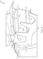
- FIG. 2 illustrates the pocket 38 with one of the blade mounts removed to show the gap 36.
- the pocket 38 may be defined by adjacent blade mounts 20, with each respective blade mount 20 defining a portion of the pocket 38.
- the gap 36 further includes a rotor relief hole 48 in the rotor disk 26.
- the rotor relief hole 48 is defined by and within the rotor disk 26.
- the rotor relief hole 48 has a rotor relief opening 50 in the fore surface 30.
- the rotor relief hole 48 may be present for similar reasons as the pocket 38.
- FIG. 1 In embodiments and as shown in FIG. 1 ,
- the rotor relief hole 48 is separate and spaced apart from the pocket 38 in the blade mount 20, i.e., the rotor relief hole 48 is exclusively defined by and within the rotor disk 26 with no internal channels within the blade mount 20 and the rotor disk 26 between the pocket 38 and the rotor relief hole 48.
- a pocket seal 52 is disposed in the pocket 38.
- the pocket seal 52 is at least disposed along the radially outward surface 46, thereby effectively sealing the gap 36 at the radially outward surface 46.
- the pocket seal 52 may fill the entire pocket 38.
- the pocket seal 52 extends to the fore opening 40.
- extending to the opening it is meant that the pocket seal 52 may be substantially flush with the fore surface 30 and terminates at the fore opening 40 or slightly outside of the pocket 38 at the fore opening 40.
- the fore opening 40 is located in the contact area where the fore plate edge 18 of the fore seal plate 14 meets the blade mount 20.
- the pocket seal 52 enables sealing engagement of the pocket seal 52 with the fore seal plate 14, for example, the fore plate edge 18.
- the fore opening 40 is aligned with the fore plate edge 18, i.e., the fore opening 40 at least partially overlaps with the fore plate edge 18, and the pocket seal 52 contacts the fore plate edge 18 to effectively seal the pocket 38.
- the pocket 38 further includes the aft opening 42 in the aft surface 32, and the pocket seal 52 further extends to the aft opening 42 to effectively seal the pocket 38 on the aft side 32 of the turbine wheel 12 as well.
- the pocket seal 52 is formed in the pocket 38 through at least one of the fore opening 40 or the aft opening 42.
- the pocket seal 52 may be formed by inserting a wire into the pocket 38, blowing a powdered metal into the pocket 38, spraying molten metal into the pocket, or the like.
- the pocket seal 52 may include metal, i.e., a material with properties characteristic of a metal such as malleability.
- the pocket seal 52 may be formed from any material that can conform to the radially outward surface 46 under centripetal force and heat while resisting breakdown.
- the pocket seal 52 is formed from L605, Haynes 188, or Hastelloy X.
- the cooling cavity 22 is defined on both the fore side and the aft side of the turbine wheel 12, with fluid communication between the fore side and the aft side facilitated through the rotor relief hole 48 and through portions of the pocket 38 that are not sealed with the pocket seal 52.
- the pocket seal 52 effectively seals the cooling cavity 22 from intrusion of hot gases into the cooling cavity 22, and further seals the cooling cavity 22 from excessive leakage of cooling gas out of the cooling cavity 22. Leakage of cooling gas from the cooling cavity 22 may reduce efficiency of the turbine engine 100.
- the turbine engine 200 is substantially similar to the turbine engine 100 of FIG. 2 .
- the rotor relief hole 248 is connected to the pocket 238 internally between the blade mount 20 and the rotor disk 26.
- the aft seal plate may be omitted with no gas flow from an internal cavity 222 formed between the fore seal plate 214 and the fore surface 230 of the turbine wheel 212 to the aft side of the turbine wheel 212.
- the pocket 238 is free from an aft opening in the aft surface 232.
- the pocket 238 may include only the fore opening 240 into the pocket 238 to enable insertion of the pocket seal 52 into the pocket 238, and a plug 254 may be disposed in the rotor relief opening 250.
- a finger 260 may extend from the fore seal plate 214 and contact the plug 254 to maintain the plug 254 in place.
- the pocket seal 252 further extends to the rotor relief hole 248, and the plug 254 may contact the pocket seal 252.
- An optional radial seal 53 may be provided, with the radial seal 53 seated between the fore seal plate 214 and the blade mounts 20, adjacent the fore plate edge 18 and abutting the pocket seal 52 to enhance sealing at the fore plate edge 18 when the radial seal 53 is present.
- an optional aft radial seal may be similarly situated as the radial seal 53.
- the turbine wheel 212 of this embodiment may be an uncooled turbine wheel, where the internal cavity 222 is uncooled and effectively provides an insulating buffer.
- a plate seal 356 covers the rotor relief opening (not shown in FIG. 4 ) and the fore opening 340 of the pocket 338.
- the plate seal 356 includes a ring that has projections 358, wherein each projection 358 covers a respective rotor relief opening and fore opening 340 of one gap 336 about a circumference of the turbine wheel 312.
- the plate seal 356 is seated in a recess (not shown) that is defined by the rotor disk 26 and blade mounts 20 in the fore surface 30 such that the plate seal 356, when installed, is substantially flush with the fore surface 30.
- the aft seal plate may be omitted and the turbine wheel 312 of this embodiment may be an uncooled turbine wheel, where the internal cavity 322 is uncooled and effectively provides an insulating buffer.
- a plate seal 456 covers the rotor relief opening 450 and the fore opening 440 of the pocket 438.
- the plate seal 456 only covers one rotor relief opening 450 and fore opening 440 pair, and a plurality of plates may be employed to cover each rotor relief opening 450 and fore opening pair 440.
- the plate seals 456 are seated in respective recesses 458 that are defined by the rotor disk 26 and blade mounts 20 in the fore surface 30 such that the plate seals 356, when installed, are substantially flush with the fore surface 30.
- the aft seal plate may be omitted and the turbine wheel 412 of this embodiment may be an uncooled turbine wheel, where the internal cavity 422 is uncooled and effectively provides an insulating buffer.
Landscapes
- Engineering & Computer Science (AREA)
- Mechanical Engineering (AREA)
- General Engineering & Computer Science (AREA)
- Turbine Rotor Nozzle Sealing (AREA)
Claims (9)
- Turbinenrad (12), umfassend:eine Rotorscheibe (26),eine Vielzahl von Turbinenschaufeln (24), wobei jede Turbinenschaufel über eine Schaufelhalterung (20) mit der Rotorscheibe wirkverbunden ist, wobei die Schaufelhalterung mit der Rotorscheibe verbunden ist, wobei die Schaufelhalterung und die Rotorscheibe eine vordere Fläche auf einer Hochdruckseite derselben und eine hintere Fläche auf einer Niederdruckseite derselben aufweisen, wobei die Schaufelhalterung eine Schaufelanbringungsfläche (34) umfasst, die sich zwischen der vorderen Fläche und der hinteren Fläche derselben erstreckt und dieselben verbindet, und wobei sich die Turbinenschaufel von der Schaufelanbringungsfläche erstreckt,dadurch gekennzeichnet, dass:ein Spalt (36) zwischen benachbarten Schaufelhalterungen definiert ist, der die Schaufelhalterungen trennt und sich in die Rotorscheibe erstreckt, und wobei der Spalt eine Tasche (38) umfasst, die durch benachbarte Schaufelhalterungen und in denselben definiert ist und eine vordere Öffnung in der vorderen Fläche aufweist,eine Rotorablassbohrung (48), die durch die Rotorscheibe und in derselben definiert ist und eine Rotorablassöffnung in der vorderen Fläche aufweist, undeine in der Tasche angeordnete Taschendichtung (52) .
- Turbinenrad nach Anspruch 1, wobei die Tasche eine nahe der Rotorscheibe gelegene, radial innere Fläche und eine entfernt von der Rotorscheibe gelegene, radial äußere Fläche aufweist und wobei die Taschendichtung entlang der radial äußeren Fläche angeordnet ist.
- Turbinenrad nach Anspruch 1, wobei die Tasche in der hinteren Fläche frei von einer Öffnung ist.
- Turbinenrad nach Anspruch 1, wobei sich die Taschendichtung zu der vorderen Öffnung erstreckt.
- Turbinenrad nach Anspruch 4, wobei die Tasche ferner eine hintere Öffnung in der hinteren Fläche umfasst und wobei sich die Taschendichtung ferner zu der hinteren Öffnung erstreckt.
- Turbinenrad nach Anspruch 1, wobei die Rotorablassbohrung innen zwischen der Schaufelhalterung und der Rotorscheibe mit der Tasche verbunden ist und wobei sich die Taschendichtung ferner zu der Rotorablassbohrung erstreckt.
- Turbinenmotor, umfassend:ein Turbinenrad nach Anspruch 1 undeine vordere Dichtungsplatte, die eine vordere Plattenkante aufweist, die um einen Umfang des Turbinenrads an den Schaufelhalterungen anliegt.
- Verfahren zur Herstellung eines Turbinenrads (12), wobei das Verfahren Folgendes umfasst:Bereitstellen einer Turbinenschaufel (24), die mit einer Schaufelhalterung (20) wirkverbunden ist, und eines Schaufelrings, der eine Vielzahl von Schaufelhalterungen umfasst, die eine vordere und eine hintere Fläche aufweisen,Verbinden des Schaufelrings mit einer Rotorscheibe (26), die eine Rotorablassbohrung definiert, wobei die Schaufelhalterungen und die Rotorscheibe aus verschiedenen Materialien ausgebildet sind, die unterschiedliche Wärmeausdehnungskoeffizienten aufweisen,Auskerben des Schaufelrings und der Rotorscheibe entlang einem Radius derselben, um dadurch einen Spalt zwischen benachbarten Schaufelhalterungen zu bilden, wobei der Spalt die Schaufelhalterungen trennt und sich in die Rotorscheibe erstreckt und wobei der Spalt eine im Voraus gebildete Tasche umfasst, die in und zwischen benachbarten Schaufelhalterungen definiert ist und eine vordere Öffnung in der vorderen Fläche der Schaufelhalterungen und optional eine hintere Öffnung in der hinteren Fläche der Schaufelhalterungen aufweist, undAusbilden einer Taschendichtung in der Tasche durch die vordere Öffnung und/oder die hintere Öffnung.
- Turbinenrad nach Anspruch 1, wobei die Rotorablassbohrung von der Tasche getrennt und beabstandet ist.
Applications Claiming Priority (1)
| Application Number | Priority Date | Filing Date | Title |
|---|---|---|---|
| US15/367,735 US10648354B2 (en) | 2016-12-02 | 2016-12-02 | Turbine wheels, turbine engines including the same, and methods of forming turbine wheels with improved seal plate sealing |
Publications (2)
| Publication Number | Publication Date |
|---|---|
| EP3330489A1 EP3330489A1 (de) | 2018-06-06 |
| EP3330489B1 true EP3330489B1 (de) | 2019-10-23 |
Family
ID=60413097
Family Applications (1)
| Application Number | Title | Priority Date | Filing Date |
|---|---|---|---|
| EP17202660.1A Active EP3330489B1 (de) | 2016-12-02 | 2017-11-21 | Turbinenräder, turbinenmotoren damit und verfahren zur herstellung von turbinenrädern mit verbesserter dichtungsplattenabdichtung |
Country Status (2)
| Country | Link |
|---|---|
| US (3) | US10648354B2 (de) |
| EP (1) | EP3330489B1 (de) |
Family Cites Families (34)
| Publication number | Priority date | Publication date | Assignee | Title |
|---|---|---|---|---|
| US2912223A (en) | 1955-03-17 | 1959-11-10 | Gen Electric | Turbine bucket vibration dampener and sealing assembly |
| US3728042A (en) | 1971-08-27 | 1973-04-17 | Westinghouse Electric Corp | Axial positioner and seal for cooled rotor blade |
| US3847506A (en) | 1973-11-29 | 1974-11-12 | Avco Corp | Turbomachine rotor |
| JP3462695B2 (ja) | 1997-03-12 | 2003-11-05 | 三菱重工業株式会社 | ガスタービン動翼シール板 |
| US6273683B1 (en) | 1999-02-05 | 2001-08-14 | Siemens Westinghouse Power Corporation | Turbine blade platform seal |
| GB0328952D0 (en) | 2003-12-12 | 2004-01-14 | Rolls Royce Plc | Nozzle guide vanes |
| JP2006214367A (ja) * | 2005-02-04 | 2006-08-17 | Mitsubishi Heavy Ind Ltd | 動翼体 |
| US7367123B2 (en) | 2005-05-12 | 2008-05-06 | General Electric Company | Coated bucket damper pin and related method |
| US7575416B2 (en) | 2006-05-18 | 2009-08-18 | United Technologies Corporation | Rotor assembly for a rotary machine |
| US7762780B2 (en) | 2007-01-25 | 2010-07-27 | Siemens Energy, Inc. | Blade assembly in a combustion turbo-machine providing reduced concentration of mechanical stress and a seal between adjacent assemblies |
| US9273563B2 (en) | 2007-12-28 | 2016-03-01 | United Technologies Corporation | Integrally bladed rotor with slotted outer rim |
| US9133720B2 (en) | 2007-12-28 | 2015-09-15 | United Technologies Corporation | Integrally bladed rotor with slotted outer rim |
| JP4939613B2 (ja) * | 2008-01-16 | 2012-05-30 | 三菱重工業株式会社 | タービン動翼 |
| US8573942B2 (en) | 2008-11-25 | 2013-11-05 | Alstom Technology Ltd. | Axial retention of a platform seal |
| US9840931B2 (en) | 2008-11-25 | 2017-12-12 | Ansaldo Energia Ip Uk Limited | Axial retention of a platform seal |
| US8393869B2 (en) | 2008-12-19 | 2013-03-12 | Solar Turbines Inc. | Turbine blade assembly including a damper |
| DE102009007468A1 (de) * | 2009-02-04 | 2010-08-19 | Mtu Aero Engines Gmbh | Integral beschaufelte Rotorscheibe für eine Turbine |
| US8322977B2 (en) | 2009-07-22 | 2012-12-04 | Siemens Energy, Inc. | Seal structure for preventing leakage of gases across a gap between two components in a turbine engine |
| US8540486B2 (en) | 2010-03-22 | 2013-09-24 | General Electric Company | Apparatus for cooling a bucket assembly |
| US8820754B2 (en) | 2010-06-11 | 2014-09-02 | Siemens Energy, Inc. | Turbine blade seal assembly |
| US20120045337A1 (en) * | 2010-08-20 | 2012-02-23 | Michael James Fedor | Turbine bucket assembly and methods for assembling same |
| US8790086B2 (en) | 2010-11-11 | 2014-07-29 | General Electric Company | Turbine blade assembly for retaining sealing and dampening elements |
| US8684695B2 (en) | 2011-01-04 | 2014-04-01 | General Electric Company | Damper coverplate and sealing arrangement for turbine bucket shank |
| US8905715B2 (en) | 2011-03-17 | 2014-12-09 | General Electric Company | Damper and seal pin arrangement for a turbine blade |
| DE102011100221B4 (de) | 2011-05-02 | 2017-03-09 | MTU Aero Engines AG | Integral beschaufelter Rotorgrundkörper, Verfahren und Strömungsmaschine |
| US9938831B2 (en) * | 2011-10-28 | 2018-04-10 | United Technologies Corporation | Spoked rotor for a gas turbine engine |
| US8967974B2 (en) | 2012-01-03 | 2015-03-03 | General Electric Company | Composite airfoil assembly |
| EP2762679A1 (de) | 2013-02-01 | 2014-08-06 | Siemens Aktiengesellschaft | Gasturbinen-Rotorschaufel und Gasturbinenrotor |
| US10458265B2 (en) | 2013-04-12 | 2019-10-29 | United Technologies Corporation | Integrally bladed rotor |
| US9777575B2 (en) * | 2014-01-20 | 2017-10-03 | Honeywell International Inc. | Turbine rotor assemblies with improved slot cavities |
| US9506365B2 (en) | 2014-04-21 | 2016-11-29 | Honeywell International Inc. | Gas turbine engine components having sealed stress relief slots and methods for the fabrication thereof |
| US10030530B2 (en) | 2014-07-31 | 2018-07-24 | United Technologies Corporation | Reversible blade rotor seal |
| US10006364B2 (en) | 2014-08-20 | 2018-06-26 | United Technologies Corporation | Gas turbine rotors |
| US10458264B2 (en) | 2015-05-05 | 2019-10-29 | United Technologies Corporation | Seal arrangement for turbine engine component |
-
2016
- 2016-12-02 US US15/367,735 patent/US10648354B2/en active Active
-
2017
- 2017-11-21 EP EP17202660.1A patent/EP3330489B1/de active Active
-
2019
- 2019-09-24 US US16/580,951 patent/US10851660B2/en active Active
-
2020
- 2020-09-08 US US17/014,547 patent/US11015472B2/en active Active
Non-Patent Citations (1)
| Title |
|---|
| None * |
Also Published As
| Publication number | Publication date |
|---|---|
| US10851660B2 (en) | 2020-12-01 |
| US20210003023A1 (en) | 2021-01-07 |
| EP3330489A1 (de) | 2018-06-06 |
| US20200141258A1 (en) | 2020-05-07 |
| US11015472B2 (en) | 2021-05-25 |
| US20180156054A1 (en) | 2018-06-07 |
| US10648354B2 (en) | 2020-05-12 |
Similar Documents
| Publication | Publication Date | Title |
|---|---|---|
| US11181006B2 (en) | Turbine tip shroud assembly with plural shroud segments having inter-segment seal arrangement | |
| EP3543468B1 (de) | Turbinenspitzendeckbandanordnung mit mehreren deckbandsegmenten mit zwischensegmentdichtungsanordnung | |
| EP2369138B1 (de) | Gasturbinenmotor mit nicht-axialsymmetrischer, oberflächenkonturierter Schaufelplattform | |
| JP4569950B2 (ja) | ガスタービンエンジンロータの先端隙間を制御するための方法及び装置 | |
| EP2971693B1 (de) | Scheibendichtungsanordnung für einen gasturbinenmotorrotor | |
| US20180372228A1 (en) | Hydrostatic non-contact seal with weight reduction pocket | |
| JP2008133829A (ja) | タービンエンジンにおける損失の削減を容易にする装置 | |
| JP2002357101A (ja) | タービンロータ | |
| EP3023594B1 (de) | Statoranordnung mit pad-schnittstelle für eine gasturbine | |
| EP2551468A1 (de) | Anordnung einer Schaufelspitzendichtung mit durchgangsverbundenen Hohlräumen und zugehöriges Betriebsverfahren | |
| EP3673153B1 (de) | Kranzdichtungsanordnung | |
| EP3047130B1 (de) | Gas turbinen dichtungsanordnung welche wabendichtungen mit keilprofil beinhaltet | |
| US9896946B2 (en) | Gas turbine engine rotor assembly and method of assembling the same | |
| US20200353577A1 (en) | Turbine wheels, turbine engines including the same, and methods of fabricating turbine wheels with improved bond line geometry | |
| EP3854995B1 (de) | Luftdichtungsanordnung | |
| US11015472B2 (en) | Turbine wheels, turbine engines including the same, and methods of forming turbine wheels with improved seal plate sealing | |
| EP2987953A2 (de) | Gasturbinenrotoren | |
| US12116897B2 (en) | Turbine stator assembly with a radial degree of freedom between a guide vane assembly and a sealing ring | |
| EP3192972B1 (de) | Durchflussaustauschablenkplatteneinsatz für eine gasturbinenmotorkomponente |
Legal Events
| Date | Code | Title | Description |
|---|---|---|---|
| PUAI | Public reference made under article 153(3) epc to a published international application that has entered the european phase |
Free format text: ORIGINAL CODE: 0009012 |
|
| STAA | Information on the status of an ep patent application or granted ep patent |
Free format text: STATUS: REQUEST FOR EXAMINATION WAS MADE |
|
| 17P | Request for examination filed |
Effective date: 20171121 |
|
| AK | Designated contracting states |
Kind code of ref document: A1 Designated state(s): AL AT BE BG CH CY CZ DE DK EE ES FI FR GB GR HR HU IE IS IT LI LT LU LV MC MK MT NL NO PL PT RO RS SE SI SK SM TR |
|
| AX | Request for extension of the european patent |
Extension state: BA ME |
|
| STAA | Information on the status of an ep patent application or granted ep patent |
Free format text: STATUS: EXAMINATION IS IN PROGRESS |
|
| 17Q | First examination report despatched |
Effective date: 20190128 |
|
| GRAP | Despatch of communication of intention to grant a patent |
Free format text: ORIGINAL CODE: EPIDOSNIGR1 |
|
| INTG | Intention to grant announced |
Effective date: 20190614 |
|
| STAA | Information on the status of an ep patent application or granted ep patent |
Free format text: STATUS: GRANT OF PATENT IS INTENDED |
|
| GRAS | Grant fee paid |
Free format text: ORIGINAL CODE: EPIDOSNIGR3 |
|
| GRAA | (expected) grant |
Free format text: ORIGINAL CODE: 0009210 |
|
| STAA | Information on the status of an ep patent application or granted ep patent |
Free format text: STATUS: THE PATENT HAS BEEN GRANTED |
|
| AK | Designated contracting states |
Kind code of ref document: B1 Designated state(s): AL AT BE BG CH CY CZ DE DK EE ES FI FR GB GR HR HU IE IS IT LI LT LU LV MC MK MT NL NO PL PT RO RS SE SI SK SM TR |
|
| REG | Reference to a national code |
Ref country code: GB Ref legal event code: FG4D |
|
| REG | Reference to a national code |
Ref country code: CH Ref legal event code: EP |
|
| REG | Reference to a national code |
Ref country code: IE Ref legal event code: FG4D |
|
| REG | Reference to a national code |
Ref country code: DE Ref legal event code: R096 Ref document number: 602017008032 Country of ref document: DE |
|
| REG | Reference to a national code |
Ref country code: AT Ref legal event code: REF Ref document number: 1193853 Country of ref document: AT Kind code of ref document: T Effective date: 20191115 |
|
| REG | Reference to a national code |
Ref country code: NL Ref legal event code: MP Effective date: 20191023 |
|
| REG | Reference to a national code |
Ref country code: LT Ref legal event code: MG4D |
|
| PG25 | Lapsed in a contracting state [announced via postgrant information from national office to epo] |
Ref country code: NL Free format text: LAPSE BECAUSE OF FAILURE TO SUBMIT A TRANSLATION OF THE DESCRIPTION OR TO PAY THE FEE WITHIN THE PRESCRIBED TIME-LIMIT Effective date: 20191023 Ref country code: LT Free format text: LAPSE BECAUSE OF FAILURE TO SUBMIT A TRANSLATION OF THE DESCRIPTION OR TO PAY THE FEE WITHIN THE PRESCRIBED TIME-LIMIT Effective date: 20191023 Ref country code: NO Free format text: LAPSE BECAUSE OF FAILURE TO SUBMIT A TRANSLATION OF THE DESCRIPTION OR TO PAY THE FEE WITHIN THE PRESCRIBED TIME-LIMIT Effective date: 20200123 Ref country code: GR Free format text: LAPSE BECAUSE OF FAILURE TO SUBMIT A TRANSLATION OF THE DESCRIPTION OR TO PAY THE FEE WITHIN THE PRESCRIBED TIME-LIMIT Effective date: 20200124 Ref country code: PL Free format text: LAPSE BECAUSE OF FAILURE TO SUBMIT A TRANSLATION OF THE DESCRIPTION OR TO PAY THE FEE WITHIN THE PRESCRIBED TIME-LIMIT Effective date: 20191023 Ref country code: SE Free format text: LAPSE BECAUSE OF FAILURE TO SUBMIT A TRANSLATION OF THE DESCRIPTION OR TO PAY THE FEE WITHIN THE PRESCRIBED TIME-LIMIT Effective date: 20191023 Ref country code: LV Free format text: LAPSE BECAUSE OF FAILURE TO SUBMIT A TRANSLATION OF THE DESCRIPTION OR TO PAY THE FEE WITHIN THE PRESCRIBED TIME-LIMIT Effective date: 20191023 Ref country code: FI Free format text: LAPSE BECAUSE OF FAILURE TO SUBMIT A TRANSLATION OF THE DESCRIPTION OR TO PAY THE FEE WITHIN THE PRESCRIBED TIME-LIMIT Effective date: 20191023 Ref country code: BG Free format text: LAPSE BECAUSE OF FAILURE TO SUBMIT A TRANSLATION OF THE DESCRIPTION OR TO PAY THE FEE WITHIN THE PRESCRIBED TIME-LIMIT Effective date: 20200123 Ref country code: PT Free format text: LAPSE BECAUSE OF FAILURE TO SUBMIT A TRANSLATION OF THE DESCRIPTION OR TO PAY THE FEE WITHIN THE PRESCRIBED TIME-LIMIT Effective date: 20200224 |
|
| PG25 | Lapsed in a contracting state [announced via postgrant information from national office to epo] |
Ref country code: IS Free format text: LAPSE BECAUSE OF FAILURE TO SUBMIT A TRANSLATION OF THE DESCRIPTION OR TO PAY THE FEE WITHIN THE PRESCRIBED TIME-LIMIT Effective date: 20200224 Ref country code: RS Free format text: LAPSE BECAUSE OF FAILURE TO SUBMIT A TRANSLATION OF THE DESCRIPTION OR TO PAY THE FEE WITHIN THE PRESCRIBED TIME-LIMIT Effective date: 20191023 Ref country code: HR Free format text: LAPSE BECAUSE OF FAILURE TO SUBMIT A TRANSLATION OF THE DESCRIPTION OR TO PAY THE FEE WITHIN THE PRESCRIBED TIME-LIMIT Effective date: 20191023 |
|
| PG25 | Lapsed in a contracting state [announced via postgrant information from national office to epo] |
Ref country code: AL Free format text: LAPSE BECAUSE OF FAILURE TO SUBMIT A TRANSLATION OF THE DESCRIPTION OR TO PAY THE FEE WITHIN THE PRESCRIBED TIME-LIMIT Effective date: 20191023 |
|
| REG | Reference to a national code |
Ref country code: DE Ref legal event code: R097 Ref document number: 602017008032 Country of ref document: DE |
|
| PG2D | Information on lapse in contracting state deleted |
Ref country code: IS |
|
| PG25 | Lapsed in a contracting state [announced via postgrant information from national office to epo] |
Ref country code: EE Free format text: LAPSE BECAUSE OF FAILURE TO SUBMIT A TRANSLATION OF THE DESCRIPTION OR TO PAY THE FEE WITHIN THE PRESCRIBED TIME-LIMIT Effective date: 20191023 Ref country code: DK Free format text: LAPSE BECAUSE OF FAILURE TO SUBMIT A TRANSLATION OF THE DESCRIPTION OR TO PAY THE FEE WITHIN THE PRESCRIBED TIME-LIMIT Effective date: 20191023 Ref country code: MC Free format text: LAPSE BECAUSE OF FAILURE TO SUBMIT A TRANSLATION OF THE DESCRIPTION OR TO PAY THE FEE WITHIN THE PRESCRIBED TIME-LIMIT Effective date: 20191023 Ref country code: ES Free format text: LAPSE BECAUSE OF FAILURE TO SUBMIT A TRANSLATION OF THE DESCRIPTION OR TO PAY THE FEE WITHIN THE PRESCRIBED TIME-LIMIT Effective date: 20191023 Ref country code: CZ Free format text: LAPSE BECAUSE OF FAILURE TO SUBMIT A TRANSLATION OF THE DESCRIPTION OR TO PAY THE FEE WITHIN THE PRESCRIBED TIME-LIMIT Effective date: 20191023 Ref country code: LU Free format text: LAPSE BECAUSE OF NON-PAYMENT OF DUE FEES Effective date: 20191121 Ref country code: RO Free format text: LAPSE BECAUSE OF FAILURE TO SUBMIT A TRANSLATION OF THE DESCRIPTION OR TO PAY THE FEE WITHIN THE PRESCRIBED TIME-LIMIT Effective date: 20191023 Ref country code: IS Free format text: LAPSE BECAUSE OF FAILURE TO SUBMIT A TRANSLATION OF THE DESCRIPTION OR TO PAY THE FEE WITHIN THE PRESCRIBED TIME-LIMIT Effective date: 20200223 |
|
| REG | Reference to a national code |
Ref country code: AT Ref legal event code: MK05 Ref document number: 1193853 Country of ref document: AT Kind code of ref document: T Effective date: 20191023 |
|
| REG | Reference to a national code |
Ref country code: BE Ref legal event code: MM Effective date: 20191130 |
|
| PLBE | No opposition filed within time limit |
Free format text: ORIGINAL CODE: 0009261 |
|
| STAA | Information on the status of an ep patent application or granted ep patent |
Free format text: STATUS: NO OPPOSITION FILED WITHIN TIME LIMIT |
|
| PG25 | Lapsed in a contracting state [announced via postgrant information from national office to epo] |
Ref country code: SM Free format text: LAPSE BECAUSE OF FAILURE TO SUBMIT A TRANSLATION OF THE DESCRIPTION OR TO PAY THE FEE WITHIN THE PRESCRIBED TIME-LIMIT Effective date: 20191023 Ref country code: SK Free format text: LAPSE BECAUSE OF FAILURE TO SUBMIT A TRANSLATION OF THE DESCRIPTION OR TO PAY THE FEE WITHIN THE PRESCRIBED TIME-LIMIT Effective date: 20191023 Ref country code: IT Free format text: LAPSE BECAUSE OF FAILURE TO SUBMIT A TRANSLATION OF THE DESCRIPTION OR TO PAY THE FEE WITHIN THE PRESCRIBED TIME-LIMIT Effective date: 20191023 |
|
| 26N | No opposition filed |
Effective date: 20200724 |
|
| PG25 | Lapsed in a contracting state [announced via postgrant information from national office to epo] |
Ref country code: FR Free format text: LAPSE BECAUSE OF NON-PAYMENT OF DUE FEES Effective date: 20191223 Ref country code: IE Free format text: LAPSE BECAUSE OF NON-PAYMENT OF DUE FEES Effective date: 20191121 |
|
| PG25 | Lapsed in a contracting state [announced via postgrant information from national office to epo] |
Ref country code: SI Free format text: LAPSE BECAUSE OF FAILURE TO SUBMIT A TRANSLATION OF THE DESCRIPTION OR TO PAY THE FEE WITHIN THE PRESCRIBED TIME-LIMIT Effective date: 20191023 Ref country code: BE Free format text: LAPSE BECAUSE OF NON-PAYMENT OF DUE FEES Effective date: 20191130 Ref country code: AT Free format text: LAPSE BECAUSE OF FAILURE TO SUBMIT A TRANSLATION OF THE DESCRIPTION OR TO PAY THE FEE WITHIN THE PRESCRIBED TIME-LIMIT Effective date: 20191023 |
|
| PG25 | Lapsed in a contracting state [announced via postgrant information from national office to epo] |
Ref country code: CY Free format text: LAPSE BECAUSE OF FAILURE TO SUBMIT A TRANSLATION OF THE DESCRIPTION OR TO PAY THE FEE WITHIN THE PRESCRIBED TIME-LIMIT Effective date: 20191023 |
|
| REG | Reference to a national code |
Ref country code: CH Ref legal event code: PL |
|
| PG25 | Lapsed in a contracting state [announced via postgrant information from national office to epo] |
Ref country code: HU Free format text: LAPSE BECAUSE OF FAILURE TO SUBMIT A TRANSLATION OF THE DESCRIPTION OR TO PAY THE FEE WITHIN THE PRESCRIBED TIME-LIMIT; INVALID AB INITIO Effective date: 20171121 Ref country code: MT Free format text: LAPSE BECAUSE OF FAILURE TO SUBMIT A TRANSLATION OF THE DESCRIPTION OR TO PAY THE FEE WITHIN THE PRESCRIBED TIME-LIMIT Effective date: 20191023 |
|
| PG25 | Lapsed in a contracting state [announced via postgrant information from national office to epo] |
Ref country code: LI Free format text: LAPSE BECAUSE OF NON-PAYMENT OF DUE FEES Effective date: 20201130 Ref country code: CH Free format text: LAPSE BECAUSE OF NON-PAYMENT OF DUE FEES Effective date: 20201130 |
|
| PG25 | Lapsed in a contracting state [announced via postgrant information from national office to epo] |
Ref country code: TR Free format text: LAPSE BECAUSE OF FAILURE TO SUBMIT A TRANSLATION OF THE DESCRIPTION OR TO PAY THE FEE WITHIN THE PRESCRIBED TIME-LIMIT Effective date: 20191023 |
|
| PG25 | Lapsed in a contracting state [announced via postgrant information from national office to epo] |
Ref country code: MK Free format text: LAPSE BECAUSE OF FAILURE TO SUBMIT A TRANSLATION OF THE DESCRIPTION OR TO PAY THE FEE WITHIN THE PRESCRIBED TIME-LIMIT Effective date: 20191023 |
|
| GBPC | Gb: european patent ceased through non-payment of renewal fee |
Effective date: 20211121 |
|
| GRAP | Despatch of communication of intention to grant a patent |
Free format text: ORIGINAL CODE: EPIDOSNIGR1 |
|
| PG25 | Lapsed in a contracting state [announced via postgrant information from national office to epo] |
Ref country code: GB Free format text: LAPSE BECAUSE OF NON-PAYMENT OF DUE FEES Effective date: 20211121 |
|
| P01 | Opt-out of the competence of the unified patent court (upc) registered |
Effective date: 20230525 |
|
| PGFP | Annual fee paid to national office [announced via postgrant information from national office to epo] |
Ref country code: DE Payment date: 20251126 Year of fee payment: 9 |