EP3330450B1 - Werkzeug und montageklammer mit verbesserten einstellmitteln und verfahren zur montage eines dachfensters in einer dachstruktur - Google Patents
Werkzeug und montageklammer mit verbesserten einstellmitteln und verfahren zur montage eines dachfensters in einer dachstruktur Download PDFInfo
- Publication number
- EP3330450B1 EP3330450B1 EP17203357.3A EP17203357A EP3330450B1 EP 3330450 B1 EP3330450 B1 EP 3330450B1 EP 17203357 A EP17203357 A EP 17203357A EP 3330450 B1 EP3330450 B1 EP 3330450B1
- Authority
- EP
- European Patent Office
- Prior art keywords
- base member
- leg
- stud
- window frame
- mounting bracket
- Prior art date
- Legal status (The legal status is an assumption and is not a legal conclusion. Google has not performed a legal analysis and makes no representation as to the accuracy of the status listed.)
- Active
Links
Images


Classifications
-
- E—FIXED CONSTRUCTIONS
- E04—BUILDING
- E04D—ROOF COVERINGS; SKY-LIGHTS; GUTTERS; ROOF-WORKING TOOLS
- E04D13/00—Special arrangements or devices in connection with roof coverings; Protection against birds; Roof drainage ; Sky-lights
- E04D13/03—Sky-lights; Domes; Ventilating sky-lights
- E04D13/0305—Supports or connecting means for sky-lights of flat or domed shape
- E04D13/031—Supports or connecting means for sky-lights of flat or domed shape characterised by a frame for connection to an inclined roof
-
- E—FIXED CONSTRUCTIONS
- E04—BUILDING
- E04F—FINISHING WORK ON BUILDINGS, e.g. STAIRS, FLOORS
- E04F21/00—Implements for finishing work on buildings
- E04F21/0007—Implements for finishing work on buildings for mounting doors, windows or frames; their fitting
- E04F21/0015—Implements for finishing work on buildings for mounting doors, windows or frames; their fitting for mounting frames
-
- E—FIXED CONSTRUCTIONS
- E06—DOORS, WINDOWS, SHUTTERS, OR ROLLER BLINDS IN GENERAL; LADDERS
- E06B—FIXED OR MOVABLE CLOSURES FOR OPENINGS IN BUILDINGS, VEHICLES, FENCES OR LIKE ENCLOSURES IN GENERAL, e.g. DOORS, WINDOWS, BLINDS, GATES
- E06B1/00—Border constructions of openings in walls, floors, or ceilings; Frames to be rigidly mounted in such openings
- E06B1/56—Fastening frames to the border of openings or to similar contiguous frames
- E06B1/60—Fastening frames to the border of openings or to similar contiguous frames by mechanical means, e.g. anchoring means
- E06B1/6015—Anchoring means
- E06B1/6023—Anchoring means completely hidden between the frame and the border of the opening, at least part of the means being previously fixed to the wall
- E06B1/603—Anchoring means completely hidden between the frame and the border of the opening, at least part of the means being previously fixed to the wall adjustable
Definitions
- the present invention relates to a mounting bracket for installation of a window frame in an inclined roof surface
- the mounting bracket comprises an angular bracket member having a first and a second leg connected integrally with each other, and a substantially plate-shaped base member having at least one opening for receiving locking means and being connected with an outer side wall of the window frame, the angular bracket member being connected to the base member in such a way that, the second leg protrudes outwards in relation to a plane perpendicular to the base member, in which locking means are provided for locking the first leg of the angular bracket member in relation to the base member in a locked condition.
- the invention furthermore relates to a method of mounting a roof window in a roof structure.
- EP 1 512 806 B1 it is known to mount a window frame in a roof using a mounting bracket comprising an angular bracket member and a base member, wherein the angular bracket member has a first leg that abuts against the base member and a second leg mounted to the roof, and the base member is mounted to the window frame.
- the first leg of the angular bracket member has an elongated slot, which provides the angular bracket member and the base member to be adjustably displaced vertically relative to each other.
- Applicant's patent no US 6,629,391 B1 discloses a mounting bracket comprising an angular bracket member having a first leg and a second leg integrally connected to each other.
- a substantially plate-shaped base member having an opening for receiving a fastening means and being connected to an outer side of the window frame.
- Adjusting means is provided for adjusting the position of the angular bracket member in a transverse direction perpendicular to the longitudinal direction of the window frame.
- Said mounting bracket comprises an angular bracket member, a base member and locking means.
- the locking means is comprised by a stud member having a head member and a screw thread member and an opening in the base member with screw threads for receiving the screw thread member.
- the adjustment means of the mounting bracket is provided by introducing a slot into the first leg of the angular bracket member.
- the screw thread member of the stud has dimensions smaller than the slot and is therefore accommodated by the slot, while the head member is dimensionally larger than the slot and cannot pass through the slot.
- the angular bracket member can be displaced to alternate positions around the screw thread member.
- the slot has two axes, a length axis and a height axis, where the angular bracket can be adjusted along both axes and any superposition of the axes.
- superposition of the two axes is meant that the position of the base member relative to the angular bracket member can be perceived as some displacement along the length axis and concurrently some displacement along the height axis.
- any superposition is meant that any displacement along either the length axis, the height axis or both is attainable, if accommodated by the dimensions of the slot.
- the base member may be attached to a window frame and the angular bracket member to a window frame, the adjustment of the two relative to each other results in a relative adjustment of window frame and sash.
- the stud is provided with a pattern, e.g. a hex pattern, in the end of the screw thread member, such that the tightening and untightening of the stud can occur by placing a hex key in the pattern and thereby engaging the stud.
- a pattern e.g. a hex pattern
- the mounting bracket may be provided with a fixation pin to enable mounting of the bracket in a window frame.
- the slot of the adjustment means may be shaped as a rectangle with rounded corners, a rectangle with right angle corners, a circle or any other suitable shape, allowing adjustment in more than one direction at the same time.
- a method of mounting a window frame in a roof window according to claim 1 is provided.
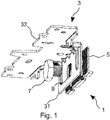
- each mounting bracket 1 comprises an angular bracket member 3, a base member 5 and locking means.
- the angular bracket member 3 comprises a first leg 31 integrally connected to a second leg 33 in a 90-degree angle.
- Adjusting means are provided for adjusting the angular bracket member 3 relative to the base member 5. As will be described in further detail below, the adjustment can take place along at least both axis of the adjusting means and any superposition of the axes.
- the adjusting means comprise a slot 9 formed in the first leg 31 of the angular bracket member 3.
- Said locking means comprises a stud 7 having a head member 71 and screw thread member 73.
- the base member 5 has an opening 53 with internal screw threads adapted for receiving said screw thread member 73 of the stud 7.
- the mounting bracket 1 comprises, the angular bracket member 3, the base member 5 and the stud 7.
- the stud 7 is aligned with the slot 9 of the first leg 31 on a second side edge 37 opposite a first side edge 35 of the first leg 31.
- On the first side edge 35 the first leg can engage with the first side edge 55 of the base member 5 through serrations formed on both side edges 35, 55.
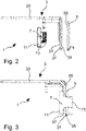
- Fig. 3 shows an embodiment of the invention in a locked condition, the head member 71 of said stud 7 abuts against the second side edge 37 of the first leg 31 of the angular bracket 3, and said screw thread member 73 of said stud 7 is received in the base member 5.
- the screw thread member 73 of the stud 7 is fully engaged with the screw threads of the opening 53 of the base member 5.
- the head member 71 of the stud 7 abuts against the second side edge 37 of the first leg 31, and the first side edge is interlocked with a first side edge 55 of the base member 5 through the serrations on both side edges 35, 55.
- Fig. 4 shows adjustment of the mounting bracket 1.
- the mounting bracket 1 is changed from the locked condition to the unlock condition by untightening the stud 7.
- Said adjustment means comprises the slot 9 in the first leg 31, where the dimensions of the slot 9 are substantially smaller than the dimensions of the head member 71 of the stud 7 and has dimensions substantially larger than said screw thread member 73.
- the screw thread member 73 is accommodated by the slot, while the head member cannot pass through the slot 9.
- the slot 9 has a length axis 11 and a height axis 13, where said stud 7 can be displaced along both axis 11, 13 and any superposition 15 of the two axes 11, 13.
- the superposition 15 of the two axes are changed and a new position of the angular bracket member relative to the base member is achieved.
- FIG. 5 shows the mounting bracket 1 mounted on an outer side of a window frame 17.
- the base member 5 is attached to the outer side of the window frame 17 and the angular bracket member 3 is interlocked with the base member 5 through the locking means comprising the stud 7 and the receiving means of the base member 5.
- An opening in the window frame allows a tool which in the embodiment shown is provided as a hex-key 18 to reach the stud 7 through the window frame.
- a pattern made in the end of the screw thread member 73 of the stud 7 is intended to cooperate with the tool, here a hexagon aperture, which allows the hex-key to engage with the stud 7 to tighten or untighten the locking means. Adjustment of the angular bracket member 3 relative to the base member 5 is therefore possible without uninstalling either window frame or sash or both.
- FIG. 6 shows a method to enable adjustment of the mounting bracket 1 through the window frame side member 101.
- a drill 102 By applying a drill 102 to inside of the window frame, as seen in Fig. 6a , a hole 103 is drilled in the window frame side member 101 at the position of the mounting bracket, as seen in Fig. 6b .
- the mounting bracket can then be adjusted by applying a hex-key 118 to the stud, as seen in Fig. 6c .
- the hole can be closed by inserting a cover plate in the hole 103.
- the cover plate may be made from a material resembling the window frame side member 101.
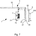
- FIG. 7 shows the mounting bracket 1, where the base member 5 has been provided with a fixation pin 105 for attaching the base member 5 to a window frame.
Landscapes
- Engineering & Computer Science (AREA)
- Architecture (AREA)
- Civil Engineering (AREA)
- Structural Engineering (AREA)
- Door And Window Frames Mounted To Openings (AREA)
- Connection Of Plates (AREA)
Claims (3)
- Verfahren zum Montieren eines Fensterrahmens in einem Dachfenster in einer Dachstruktur, wobei der Fensterrahmen eine Montagehalterung (1) umfasst, die ein winkelförmiges Halterungsglied (3) mit einem ersten (31) und einem zweiten Schenkel (33) umfasst, die integral miteinander verbunden sind, undein im Wesentlichen plattenförmiges Basisglied (5), das mindestens eine Öffnung (53) zur Aufnahme von Verriegelungsmitteln (7) hat und mit einer äußeren Seitenwand des Fensterrahmens (17) verbunden ist,wobei das winkelförmige Halterungsglied (3) so mit dem Basisglied (5) verbunden ist, dass der zweite Schenkel (33) bezüglich einer senkrecht zu dem Basisglied (5) verlaufenden Ebene nach außen ragt, wobeiVerriegelungsmittel vorgesehen sind, um den ersten Schenkel (31) des winkelförmigen Halterungsglieds (3) bezüglich des Basisglieds (5) in einem verriegelten Zustand zu verriegeln, wobei die Verriegelungsmittel einen Bolzen (7) umfassen, der ein Kopfglied (71) und ein Schraubengewindeglied (73) hat, um mit einer Öffnung in dem Basisglied (5) mit einem Schraubengewinde zur Aufnahme des Schraubengewindeglieds (73) zusammenzuwirken,wobei Verstellmittel vorgesehen sind, die einen geschlossenen Schlitz (9) umfassen, wobei der Schlitz (9) vordefinierte begrenzte Abmessungen hat, die ein Verstellen des winkelförmigen Halterungsglieds (3) bezüglich des Basisglieds (5) in einer parallel zu dem ersten Schenkel verlaufenden Ebene sowohl entlang einer Längenachse (11) als auch einer Höhenachse (13) der Verstellmittel und entlang einer etwaigen Überlagerung der beiden Achsen gestatten, wenn durch die Abmessungen des Schlitzes (9) gestattet, und umfassend die folgenden Schritte:Bereitstellen eines Dachfensters, das einen Fensterrahmen und einen Fensterflügel umfasst,Bohren eines Lochs (103) durch ein Fensterrahmenseitenglied (101),Bereitstellen der Montagehalterung (1),Anlegen des Kopfglieds (71) des Bolzens (7) an die zweite Seite des ersten Schenkels, so dass das Schraubengewindeglied (73) von dem Schlitz (9) aufgenommen wird,Montieren des Basisglieds der Montagehalterung (1) an dem Fensterrahmen und Montieren des winkelförmigen Halterungsglieds an dem Fensterrahmen,Anwenden eines zusammenwirkenden Werkzeugs mit einer Spitze, die zu einem Muster eines Kopfglieds (71) des Bolzens (7) passt,Schrauben des Schraubengewindeglieds (73) durch die Öffnung (53) des Basisglieds (5), wodurch entwederder Bolzen (7) gelockert wird, um Positionsverstellungen der Montagehalterung (1) durchzuführen, oderder Bolzen (7) angezogen wird, um die Montagehalterung (1) in Position zu verriegeln,wobei eine Abdeckplatte bereitgestellt wird, um das Loch (103) nach Anziehen des Bolzens (7) abzudecken.
- Montagehalterung (1) und zusammenwirkendes Werkzeug zur Verwendung in dem Verfahren von Anspruch 1, wobei die Montagehalterung (1) ein winkelförmiges Halterungsglied (3) mit einem ersten (31) und einem zweiten Schenkel (33) umfasst, die integral miteinander verbunden sind, und ein im Wesentlichen plattenförmiges Basisglied, das mindestens eine Öffnung zur Aufnahme von Verriegelungsmitteln hat und mit einer äußeren Seitenwand des Fensterrahmens (17) verbunden ist, wobei das winkelförmige Halterungsglied (3) so mit dem Basisglied (5) verbunden ist, dass der zweite Schenkel (33) bezüglich einer senkrecht zu dem Basisglied (5) verlaufenden Ebene nach außen ragt, wobei Verriegelungsmittel vorgesehen sind, um den ersten Schenkel (31) des winkelförmigen Halterungsglieds (3) bezüglich des Basisglieds (5) in einem verriegelten Zustand zu verriegeln,
wobei Verstellmittel zum Verstellen des winkelförmigen Halterungsglieds (3) bezüglich des Basisglieds (5) vorgesehen sind, wobei die Verstellmittel einen geschlossenen Schlitz (9) mit vordefinierten begrenzten Abmessungen umfassen, die ein Verstellen des winkelförmigen Halterungsglieds (3) bezüglich des Basisglieds (5) in einer parallel zu dem ersten Schenkel verlaufenden Ebene entlang einer Längenachse (11) und einer Höhenachse (13) der Verstellmittel und entlang einer etwaigen Überlagerung der Achsen gestatten, wobei die Verriegelungsmittel einen Bolzen (7) umfassen, der ein Kopfglied (71) und ein Schraubengewindeglied (73) hat, um mit einer Öffnung in dem Basisglied (5) mit einem Schraubengewinde zur Aufnahme des Schraubengewindeglieds (73) zusammenzuwirken, und wobei das Kopfglied (71) des Bolzens (7) mit Muster versehen ist, das dem zusammenwirkenden Werkzeugs entspricht. - Montagehalterung (1) und Werkzeug nach Anspruch 2, wobei das Muster eine seckseckige Öffnung ist und das Werkzeug ein Inbusschlüssel (18, 118) ist.
Applications Claiming Priority (1)
| Application Number | Priority Date | Filing Date | Title |
|---|---|---|---|
| DKPA201670963A DK179921B1 (en) | 2016-12-05 | 2016-12-05 | Mounting bracket with improved adjustment means and method of mounting a roof window in a roof structure |
Publications (2)
| Publication Number | Publication Date |
|---|---|
| EP3330450A1 EP3330450A1 (de) | 2018-06-06 |
| EP3330450B1 true EP3330450B1 (de) | 2022-11-09 |
Family
ID=60452484
Family Applications (1)
| Application Number | Title | Priority Date | Filing Date |
|---|---|---|---|
| EP17203357.3A Active EP3330450B1 (de) | 2016-12-05 | 2017-11-23 | Werkzeug und montageklammer mit verbesserten einstellmitteln und verfahren zur montage eines dachfensters in einer dachstruktur |
Country Status (4)
| Country | Link |
|---|---|
| EP (1) | EP3330450B1 (de) |
| CN (1) | CN108149857A (de) |
| DK (1) | DK179921B1 (de) |
| PL (1) | PL3330450T3 (de) |
Families Citing this family (3)
| Publication number | Priority date | Publication date | Assignee | Title |
|---|---|---|---|---|
| CN108824782B (zh) * | 2018-07-30 | 2024-07-23 | 阳泉森宝建材有限公司 | 一种瓷砖调整器 |
| DK181853B1 (en) * | 2022-03-31 | 2025-02-20 | Vkr Holding As | Roof window with a mounting bracket and method of installing the roof window |
| FR3140395B1 (fr) * | 2022-09-30 | 2024-11-08 | Plasti Process | Dispositif de fixation d’un dormant d’une menuiserie comprenant des moyens de maintien et un moyen de manœuvre desdits moyens de maintien |
Family Cites Families (5)
| Publication number | Priority date | Publication date | Assignee | Title |
|---|---|---|---|---|
| NL7404258A (en) * | 1974-03-28 | 1975-09-30 | Lips Aluminium Bv | Interior door mounting frame - has anchor plate on wall clamped between second plate and side of column |
| DE4412505C1 (de) * | 1994-04-12 | 1995-06-29 | Georg Nyhuis | Vorrichtung zur Befestigung von Fassadenelementen |
| US6629391B1 (en) * | 2000-07-06 | 2003-10-07 | Vkr Holding A/S | Window for installation in a roof and a mounting bracket for use in the installation of roof penetrating structures |
| EP1512806B1 (de) * | 2003-08-30 | 2010-07-28 | Roto Frank Ag | Montagewinkelvorrichtung für Dachfenster |
| US8333359B2 (en) * | 2009-07-31 | 2012-12-18 | Randy Gordon | Jamb mounting bracket and method of use |
-
2016
- 2016-12-05 DK DKPA201670963A patent/DK179921B1/en active IP Right Grant
-
2017
- 2017-11-23 EP EP17203357.3A patent/EP3330450B1/de active Active
- 2017-11-23 PL PL17203357.3T patent/PL3330450T3/pl unknown
- 2017-12-01 CN CN201711249822.3A patent/CN108149857A/zh active Pending
Also Published As
| Publication number | Publication date |
|---|---|
| EP3330450A1 (de) | 2018-06-06 |
| CN108149857A (zh) | 2018-06-12 |
| PL3330450T3 (pl) | 2023-03-13 |
| DK179921B1 (en) | 2019-10-08 |
| DK201670963A1 (en) | 2018-06-14 |
Similar Documents
| Publication | Publication Date | Title |
|---|---|---|
| US9567784B2 (en) | Hook latch fitted with a positioning device and a method for assembling such a latch | |
| EP3330450A1 (de) | Montageklammer mit verbesserten einstellmitteln und verfahren zur montage eines dachfensters in einer dachstruktur | |
| US6629391B1 (en) | Window for installation in a roof and a mounting bracket for use in the installation of roof penetrating structures | |
| US20110112536A1 (en) | Polyaxial bushing for locking plate | |
| US8439410B2 (en) | Prehung door jamb insert with security and adjustment features | |
| WO2011082228A1 (en) | Recessed mount with stowed clamps | |
| US8245448B2 (en) | Door plug | |
| US4667992A (en) | Security bar for inwardly swinging doors | |
| US8863358B2 (en) | Adjustable hinge | |
| US11549269B2 (en) | Standoff for mounting panel and method for mounting panels | |
| US12129696B2 (en) | Door lock device | |
| EP3608551A1 (de) | Klammeranker zur befestigung von schmiedewaren an ein hohlprofil eines fensters oder einer tür | |
| WO2019195724A1 (en) | Combined anchor, fastener and leveling assembly | |
| US20110175378A1 (en) | Adjustable door strike for latch and deadbolt | |
| EP3296482B1 (de) | Einbruchhemmender anschluss für gebäudeverkleidung | |
| US11940002B2 (en) | Adjustable potted insert | |
| KR102719870B1 (ko) | 볼트 고정용 와샤의 위치고정 지그장치, 및 그 지그장치를 이용한 볼트 체결방법 | |
| EP1327544B1 (de) | Vorrichtung und Verfahren zur Einstellung und Fixierung der Neigung der Laufführung eines Seitenfensters in einem Motorfahrzeug | |
| CA3090021C (en) | Adjustable potted insert | |
| KR200239981Y1 (ko) | 앵커 볼트의 체결구조 | |
| JP4443427B2 (ja) | 施錠装置 | |
| TWI700138B (zh) | 導引裝置 | |
| KR20110049174A (ko) | 도어용 하부 힌지 조립체 | |
| CA3281910A1 (en) | Fenestration unit with installation features and associated methods | |
| JP2023101225A (ja) | 胴縁固定構造 |
Legal Events
| Date | Code | Title | Description |
|---|---|---|---|
| PUAI | Public reference made under article 153(3) epc to a published international application that has entered the european phase |
Free format text: ORIGINAL CODE: 0009012 |
|
| STAA | Information on the status of an ep patent application or granted ep patent |
Free format text: STATUS: THE APPLICATION HAS BEEN PUBLISHED |
|
| AK | Designated contracting states |
Kind code of ref document: A1 Designated state(s): AL AT BE BG CH CY CZ DE DK EE ES FI FR GB GR HR HU IE IS IT LI LT LU LV MC MK MT NL NO PL PT RO RS SE SI SK SM TR |
|
| AX | Request for extension of the european patent |
Extension state: BA ME |
|
| STAA | Information on the status of an ep patent application or granted ep patent |
Free format text: STATUS: REQUEST FOR EXAMINATION WAS MADE |
|
| 17P | Request for examination filed |
Effective date: 20181206 |
|
| RBV | Designated contracting states (corrected) |
Designated state(s): AL AT BE BG CH CY CZ DE DK EE ES FI FR GB GR HR HU IE IS IT LI LT LU LV MC MK MT NL NO PL PT RO RS SE SI SK SM TR |
|
| STAA | Information on the status of an ep patent application or granted ep patent |
Free format text: STATUS: EXAMINATION IS IN PROGRESS |
|
| 17Q | First examination report despatched |
Effective date: 20200116 |
|
| GRAP | Despatch of communication of intention to grant a patent |
Free format text: ORIGINAL CODE: EPIDOSNIGR1 |
|
| STAA | Information on the status of an ep patent application or granted ep patent |
Free format text: STATUS: GRANT OF PATENT IS INTENDED |
|
| RIC1 | Information provided on ipc code assigned before grant |
Ipc: E06B 1/60 20060101ALN20220602BHEP Ipc: E04D 13/03 20060101AFI20220602BHEP |
|
| INTG | Intention to grant announced |
Effective date: 20220628 |
|
| GRAS | Grant fee paid |
Free format text: ORIGINAL CODE: EPIDOSNIGR3 |
|
| GRAA | (expected) grant |
Free format text: ORIGINAL CODE: 0009210 |
|
| STAA | Information on the status of an ep patent application or granted ep patent |
Free format text: STATUS: THE PATENT HAS BEEN GRANTED |
|
| AK | Designated contracting states |
Kind code of ref document: B1 Designated state(s): AL AT BE BG CH CY CZ DE DK EE ES FI FR GB GR HR HU IE IS IT LI LT LU LV MC MK MT NL NO PL PT RO RS SE SI SK SM TR |
|
| REG | Reference to a national code |
Ref country code: GB Ref legal event code: FG4D |
|
| REG | Reference to a national code |
Ref country code: CH Ref legal event code: EP Ref country code: AT Ref legal event code: REF Ref document number: 1530458 Country of ref document: AT Kind code of ref document: T Effective date: 20221115 |
|
| REG | Reference to a national code |
Ref country code: DE Ref legal event code: R096 Ref document number: 602017063480 Country of ref document: DE |
|
| REG | Reference to a national code |
Ref country code: IE Ref legal event code: FG4D |
|
| REG | Reference to a national code |
Ref country code: LT Ref legal event code: MG9D |
|
| REG | Reference to a national code |
Ref country code: NL Ref legal event code: MP Effective date: 20221109 |
|
| REG | Reference to a national code |
Ref country code: AT Ref legal event code: MK05 Ref document number: 1530458 Country of ref document: AT Kind code of ref document: T Effective date: 20221109 |
|
| PG25 | Lapsed in a contracting state [announced via postgrant information from national office to epo] |
Ref country code: SE Free format text: LAPSE BECAUSE OF FAILURE TO SUBMIT A TRANSLATION OF THE DESCRIPTION OR TO PAY THE FEE WITHIN THE PRESCRIBED TIME-LIMIT Effective date: 20221109 Ref country code: PT Free format text: LAPSE BECAUSE OF FAILURE TO SUBMIT A TRANSLATION OF THE DESCRIPTION OR TO PAY THE FEE WITHIN THE PRESCRIBED TIME-LIMIT Effective date: 20230309 Ref country code: NO Free format text: LAPSE BECAUSE OF FAILURE TO SUBMIT A TRANSLATION OF THE DESCRIPTION OR TO PAY THE FEE WITHIN THE PRESCRIBED TIME-LIMIT Effective date: 20230209 Ref country code: LT Free format text: LAPSE BECAUSE OF FAILURE TO SUBMIT A TRANSLATION OF THE DESCRIPTION OR TO PAY THE FEE WITHIN THE PRESCRIBED TIME-LIMIT Effective date: 20221109 Ref country code: FI Free format text: LAPSE BECAUSE OF FAILURE TO SUBMIT A TRANSLATION OF THE DESCRIPTION OR TO PAY THE FEE WITHIN THE PRESCRIBED TIME-LIMIT Effective date: 20221109 Ref country code: ES Free format text: LAPSE BECAUSE OF FAILURE TO SUBMIT A TRANSLATION OF THE DESCRIPTION OR TO PAY THE FEE WITHIN THE PRESCRIBED TIME-LIMIT Effective date: 20221109 Ref country code: AT Free format text: LAPSE BECAUSE OF FAILURE TO SUBMIT A TRANSLATION OF THE DESCRIPTION OR TO PAY THE FEE WITHIN THE PRESCRIBED TIME-LIMIT Effective date: 20221109 |
|
| PG25 | Lapsed in a contracting state [announced via postgrant information from national office to epo] |
Ref country code: RS Free format text: LAPSE BECAUSE OF FAILURE TO SUBMIT A TRANSLATION OF THE DESCRIPTION OR TO PAY THE FEE WITHIN THE PRESCRIBED TIME-LIMIT Effective date: 20221109 Ref country code: LV Free format text: LAPSE BECAUSE OF FAILURE TO SUBMIT A TRANSLATION OF THE DESCRIPTION OR TO PAY THE FEE WITHIN THE PRESCRIBED TIME-LIMIT Effective date: 20221109 Ref country code: IS Free format text: LAPSE BECAUSE OF FAILURE TO SUBMIT A TRANSLATION OF THE DESCRIPTION OR TO PAY THE FEE WITHIN THE PRESCRIBED TIME-LIMIT Effective date: 20230309 Ref country code: HR Free format text: LAPSE BECAUSE OF FAILURE TO SUBMIT A TRANSLATION OF THE DESCRIPTION OR TO PAY THE FEE WITHIN THE PRESCRIBED TIME-LIMIT Effective date: 20221109 Ref country code: GR Free format text: LAPSE BECAUSE OF FAILURE TO SUBMIT A TRANSLATION OF THE DESCRIPTION OR TO PAY THE FEE WITHIN THE PRESCRIBED TIME-LIMIT Effective date: 20230210 |
|
| PG25 | Lapsed in a contracting state [announced via postgrant information from national office to epo] |
Ref country code: NL Free format text: LAPSE BECAUSE OF FAILURE TO SUBMIT A TRANSLATION OF THE DESCRIPTION OR TO PAY THE FEE WITHIN THE PRESCRIBED TIME-LIMIT Effective date: 20221109 |
|
| REG | Reference to a national code |
Ref country code: CH Ref legal event code: PL |
|
| REG | Reference to a national code |
Ref country code: BE Ref legal event code: MM Effective date: 20221130 |
|
| PG25 | Lapsed in a contracting state [announced via postgrant information from national office to epo] |
Ref country code: SM Free format text: LAPSE BECAUSE OF FAILURE TO SUBMIT A TRANSLATION OF THE DESCRIPTION OR TO PAY THE FEE WITHIN THE PRESCRIBED TIME-LIMIT Effective date: 20221109 Ref country code: RO Free format text: LAPSE BECAUSE OF FAILURE TO SUBMIT A TRANSLATION OF THE DESCRIPTION OR TO PAY THE FEE WITHIN THE PRESCRIBED TIME-LIMIT Effective date: 20221109 Ref country code: LI Free format text: LAPSE BECAUSE OF NON-PAYMENT OF DUE FEES Effective date: 20221130 Ref country code: EE Free format text: LAPSE BECAUSE OF FAILURE TO SUBMIT A TRANSLATION OF THE DESCRIPTION OR TO PAY THE FEE WITHIN THE PRESCRIBED TIME-LIMIT Effective date: 20221109 Ref country code: DK Free format text: LAPSE BECAUSE OF FAILURE TO SUBMIT A TRANSLATION OF THE DESCRIPTION OR TO PAY THE FEE WITHIN THE PRESCRIBED TIME-LIMIT Effective date: 20221109 Ref country code: CZ Free format text: LAPSE BECAUSE OF FAILURE TO SUBMIT A TRANSLATION OF THE DESCRIPTION OR TO PAY THE FEE WITHIN THE PRESCRIBED TIME-LIMIT Effective date: 20221109 Ref country code: CH Free format text: LAPSE BECAUSE OF NON-PAYMENT OF DUE FEES Effective date: 20221130 |
|
| REG | Reference to a national code |
Ref country code: DE Ref legal event code: R097 Ref document number: 602017063480 Country of ref document: DE |
|
| PG25 | Lapsed in a contracting state [announced via postgrant information from national office to epo] |
Ref country code: SK Free format text: LAPSE BECAUSE OF FAILURE TO SUBMIT A TRANSLATION OF THE DESCRIPTION OR TO PAY THE FEE WITHIN THE PRESCRIBED TIME-LIMIT Effective date: 20221109 Ref country code: LU Free format text: LAPSE BECAUSE OF NON-PAYMENT OF DUE FEES Effective date: 20221123 Ref country code: AL Free format text: LAPSE BECAUSE OF FAILURE TO SUBMIT A TRANSLATION OF THE DESCRIPTION OR TO PAY THE FEE WITHIN THE PRESCRIBED TIME-LIMIT Effective date: 20221109 |
|
| PLBE | No opposition filed within time limit |
Free format text: ORIGINAL CODE: 0009261 |
|
| STAA | Information on the status of an ep patent application or granted ep patent |
Free format text: STATUS: NO OPPOSITION FILED WITHIN TIME LIMIT |
|
| 26N | No opposition filed |
Effective date: 20230810 |
|
| PG25 | Lapsed in a contracting state [announced via postgrant information from national office to epo] |
Ref country code: IE Free format text: LAPSE BECAUSE OF NON-PAYMENT OF DUE FEES Effective date: 20221123 |
|
| PG25 | Lapsed in a contracting state [announced via postgrant information from national office to epo] |
Ref country code: SI Free format text: LAPSE BECAUSE OF FAILURE TO SUBMIT A TRANSLATION OF THE DESCRIPTION OR TO PAY THE FEE WITHIN THE PRESCRIBED TIME-LIMIT Effective date: 20221109 Ref country code: BE Free format text: LAPSE BECAUSE OF NON-PAYMENT OF DUE FEES Effective date: 20221130 |
|
| PG25 | Lapsed in a contracting state [announced via postgrant information from national office to epo] |
Ref country code: HU Free format text: LAPSE BECAUSE OF FAILURE TO SUBMIT A TRANSLATION OF THE DESCRIPTION OR TO PAY THE FEE WITHIN THE PRESCRIBED TIME-LIMIT; INVALID AB INITIO Effective date: 20171123 |
|
| PG25 | Lapsed in a contracting state [announced via postgrant information from national office to epo] |
Ref country code: CY Free format text: LAPSE BECAUSE OF FAILURE TO SUBMIT A TRANSLATION OF THE DESCRIPTION OR TO PAY THE FEE WITHIN THE PRESCRIBED TIME-LIMIT Effective date: 20221109 |
|
| PG25 | Lapsed in a contracting state [announced via postgrant information from national office to epo] |
Ref country code: MK Free format text: LAPSE BECAUSE OF FAILURE TO SUBMIT A TRANSLATION OF THE DESCRIPTION OR TO PAY THE FEE WITHIN THE PRESCRIBED TIME-LIMIT Effective date: 20221109 Ref country code: IT Free format text: LAPSE BECAUSE OF FAILURE TO SUBMIT A TRANSLATION OF THE DESCRIPTION OR TO PAY THE FEE WITHIN THE PRESCRIBED TIME-LIMIT Effective date: 20221109 |
|
| PG25 | Lapsed in a contracting state [announced via postgrant information from national office to epo] |
Ref country code: MC Free format text: LAPSE BECAUSE OF FAILURE TO SUBMIT A TRANSLATION OF THE DESCRIPTION OR TO PAY THE FEE WITHIN THE PRESCRIBED TIME-LIMIT Effective date: 20221109 |
|
| PG25 | Lapsed in a contracting state [announced via postgrant information from national office to epo] |
Ref country code: TR Free format text: LAPSE BECAUSE OF FAILURE TO SUBMIT A TRANSLATION OF THE DESCRIPTION OR TO PAY THE FEE WITHIN THE PRESCRIBED TIME-LIMIT Effective date: 20221109 Ref country code: MC Free format text: LAPSE BECAUSE OF FAILURE TO SUBMIT A TRANSLATION OF THE DESCRIPTION OR TO PAY THE FEE WITHIN THE PRESCRIBED TIME-LIMIT Effective date: 20221109 |
|
| PG25 | Lapsed in a contracting state [announced via postgrant information from national office to epo] |
Ref country code: BG Free format text: LAPSE BECAUSE OF FAILURE TO SUBMIT A TRANSLATION OF THE DESCRIPTION OR TO PAY THE FEE WITHIN THE PRESCRIBED TIME-LIMIT Effective date: 20221109 |
|
| PG25 | Lapsed in a contracting state [announced via postgrant information from national office to epo] |
Ref country code: MT Free format text: LAPSE BECAUSE OF FAILURE TO SUBMIT A TRANSLATION OF THE DESCRIPTION OR TO PAY THE FEE WITHIN THE PRESCRIBED TIME-LIMIT Effective date: 20221109 |
|
| PGFP | Annual fee paid to national office [announced via postgrant information from national office to epo] |
Ref country code: DE Payment date: 20251007 Year of fee payment: 9 |
|
| PGFP | Annual fee paid to national office [announced via postgrant information from national office to epo] |
Ref country code: GB Payment date: 20251016 Year of fee payment: 9 |
|
| PGFP | Annual fee paid to national office [announced via postgrant information from national office to epo] |
Ref country code: FR Payment date: 20251008 Year of fee payment: 9 |
|
| PGFP | Annual fee paid to national office [announced via postgrant information from national office to epo] |
Ref country code: PL Payment date: 20251014 Year of fee payment: 9 |