EP3330185B1 - Aktuatorprüfung - Google Patents
Aktuatorprüfung Download PDFInfo
- Publication number
- EP3330185B1 EP3330185B1 EP17203484.5A EP17203484A EP3330185B1 EP 3330185 B1 EP3330185 B1 EP 3330185B1 EP 17203484 A EP17203484 A EP 17203484A EP 3330185 B1 EP3330185 B1 EP 3330185B1
- Authority
- EP
- European Patent Office
- Prior art keywords
- linear actuator
- test
- actuator
- force
- distance
- Prior art date
- Legal status (The legal status is an assumption and is not a legal conclusion. Google has not performed a legal analysis and makes no representation as to the accuracy of the status listed.)
- Active
Links
Images
Classifications
-
- G—PHYSICS
- G01—MEASURING; TESTING
- G01M—TESTING STATIC OR DYNAMIC BALANCE OF MACHINES OR STRUCTURES; TESTING OF STRUCTURES OR APPARATUS, NOT OTHERWISE PROVIDED FOR
- G01M13/00—Testing of machine parts
- G01M13/02—Gearings; Transmission mechanisms
-
- G—PHYSICS
- G01—MEASURING; TESTING
- G01M—TESTING STATIC OR DYNAMIC BALANCE OF MACHINES OR STRUCTURES; TESTING OF STRUCTURES OR APPARATUS, NOT OTHERWISE PROVIDED FOR
- G01M99/00—Subject matter not provided for in other groups of this subclass
- G01M99/008—Subject matter not provided for in other groups of this subclass by doing functionality tests
-
- F—MECHANICAL ENGINEERING; LIGHTING; HEATING; WEAPONS; BLASTING
- F15—FLUID-PRESSURE ACTUATORS; HYDRAULICS OR PNEUMATICS IN GENERAL
- F15B—SYSTEMS ACTING BY MEANS OF FLUIDS IN GENERAL; FLUID-PRESSURE ACTUATORS, e.g. SERVOMOTORS; DETAILS OF FLUID-PRESSURE SYSTEMS, NOT OTHERWISE PROVIDED FOR
- F15B19/00—Testing; Calibrating; Fault detection or monitoring; Simulation or modelling of fluid-pressure systems or apparatus not otherwise provided for
- F15B19/005—Fault detection or monitoring
-
- B—PERFORMING OPERATIONS; TRANSPORTING
- B64—AIRCRAFT; AVIATION; COSMONAUTICS
- B64C—AEROPLANES; HELICOPTERS
- B64C13/00—Control systems or transmitting systems for actuating flying-control surfaces, lift-increasing flaps, air brakes, or spoilers
- B64C13/24—Transmitting means
- B64C13/38—Transmitting means with power amplification
-
- B—PERFORMING OPERATIONS; TRANSPORTING
- B64—AIRCRAFT; AVIATION; COSMONAUTICS
- B64F—GROUND OR AIRCRAFT-CARRIER-DECK INSTALLATIONS SPECIALLY ADAPTED FOR USE IN CONNECTION WITH AIRCRAFT; DESIGNING, MANUFACTURING, ASSEMBLING, CLEANING, MAINTAINING OR REPAIRING AIRCRAFT, NOT OTHERWISE PROVIDED FOR; HANDLING, TRANSPORTING, TESTING OR INSPECTING AIRCRAFT COMPONENTS, NOT OTHERWISE PROVIDED FOR
- B64F5/00—Designing, manufacturing, assembling, cleaning, maintaining or repairing aircraft, not otherwise provided for; Handling, transporting, testing or inspecting aircraft components, not otherwise provided for
- B64F5/60—Testing or inspecting aircraft components or systems
-
- F—MECHANICAL ENGINEERING; LIGHTING; HEATING; WEAPONS; BLASTING
- F15—FLUID-PRESSURE ACTUATORS; HYDRAULICS OR PNEUMATICS IN GENERAL
- F15B—SYSTEMS ACTING BY MEANS OF FLUIDS IN GENERAL; FLUID-PRESSURE ACTUATORS, e.g. SERVOMOTORS; DETAILS OF FLUID-PRESSURE SYSTEMS, NOT OTHERWISE PROVIDED FOR
- F15B19/00—Testing; Calibrating; Fault detection or monitoring; Simulation or modelling of fluid-pressure systems or apparatus not otherwise provided for
-
- G—PHYSICS
- G01—MEASURING; TESTING
- G01M—TESTING STATIC OR DYNAMIC BALANCE OF MACHINES OR STRUCTURES; TESTING OF STRUCTURES OR APPARATUS, NOT OTHERWISE PROVIDED FOR
- G01M13/00—Testing of machine parts
-
- F—MECHANICAL ENGINEERING; LIGHTING; HEATING; WEAPONS; BLASTING
- F15—FLUID-PRESSURE ACTUATORS; HYDRAULICS OR PNEUMATICS IN GENERAL
- F15B—SYSTEMS ACTING BY MEANS OF FLUIDS IN GENERAL; FLUID-PRESSURE ACTUATORS, e.g. SERVOMOTORS; DETAILS OF FLUID-PRESSURE SYSTEMS, NOT OTHERWISE PROVIDED FOR
- F15B2211/00—Circuits for servomotor systems
- F15B2211/70—Output members, e.g. hydraulic motors or cylinders or control therefor
- F15B2211/705—Output members, e.g. hydraulic motors or cylinders or control therefor characterised by the type of output members or actuators
- F15B2211/7051—Linear output members
-
- F—MECHANICAL ENGINEERING; LIGHTING; HEATING; WEAPONS; BLASTING
- F15—FLUID-PRESSURE ACTUATORS; HYDRAULICS OR PNEUMATICS IN GENERAL
- F15B—SYSTEMS ACTING BY MEANS OF FLUIDS IN GENERAL; FLUID-PRESSURE ACTUATORS, e.g. SERVOMOTORS; DETAILS OF FLUID-PRESSURE SYSTEMS, NOT OTHERWISE PROVIDED FOR
- F15B2211/00—Circuits for servomotor systems
- F15B2211/80—Other types of control related to particular problems or conditions
- F15B2211/855—Testing of fluid pressure systems
Definitions
- the present invention relates to an apparatus for in-situ testing of a linear actuator; and a method of testing a linear actuator in-situ.
- Aircraft spoilers are typically actuated by linear actuators. When an aircraft is cruising, the airflow over the wing exerts a suction force on the spoilers, which (if not resisted) would cause the spoilers to lift away from the upper surface of the wing. This would disrupt the aerodynamic profile of the wing, and would consequently reduce the fuel efficiency of the aircraft.
- the spoiler actuators are therefore arranged to resist this suction force and hold the spoilers in a fully retracted configuration whilst the aircraft is cruising.
- a spoiler actuator may become less effective at holding the spoiler down against the aerodynamic suction force (e.g. because they are in need of maintenance or replacement). This may not affect the actuators ability to deploy and position the spoiler when deployed, so it may not be noticed by flight or ground crew. However; it can negatively impact the fuel efficiency of the aircraft, as described above, and so it is desirable to detect when a spoiler actuator has become less effective at holding the spoiler in the fully retracted position.
- CN 105298988 describes a device for measuring leakage in a hydraulic cylinder, which has a loading hydraulic cylinder that is installed with a testing hydraulic cylinder to measure an amount of displacement of a piston using a displacement sensor.
- a first aspect of the present invention provides an apparatus for in-situ testing of a linear actuator which is configured to exert an actuation force in an actuation direction by movement of a first part of the linear actuator relative to a second part of the linear actuator.
- the apparatus comprises a test device, a test actuator and a measurement device.
- the test device comprises a first surface configured to contact the first part of the linear actuator during operation of the apparatus, and a second surface configured to contact the second part of the linear actuator during operation of the apparatus.
- the second surface is moveable relative to the first surface to alter a distance between the first surface and the second surface.
- the test actuator is configured to exert a test force in a direction opposite to the actuation direction when the apparatus is in use to test the linear actuator, the test force being to drive movement of the second surface away from the first surface.
- the measurement device is for detecting a change in the distance between the first surface and the second surface.
- the linear actuator comprises an extending arm
- the test device is configured to enclose a cross-section of the extending arm during operation of the apparatus to test the linear actuator.
- the test device comprises a load reaction component and a force generation component, and the first surface is comprised in the load reaction component and the second surface is comprised in the force generation component.
- the load reaction component is configured to react a maximum actuation force exertable by the linear actuator.
- the force generation component comprises one or more extendible members connected to the test actuator.
- the one or more extendible members may be in contact with the load reaction component such that loads can be transmitted from the force generation component to the load reaction component via the one or more extendible members.
- the one or more extendible members may be configured such that extension of the one or more extendible members increases the distance between the first surface and the second surface.
- the test actuator may be configured to drive extension of the one or more extendible members.
- the test actuator is configured to exert the test force according to at least one predetermined parameter.
- the at least one predetermined parameter includes one or more of: a magnitude of the test force; a direction of the test force; a time period during which the test force is continuously exerted.
- the test actuator comprises a hydraulic actuator.
- the configuration of the first surface is arranged to match the configuration of a surface on the first part contacted by the first surface during operation of the actuator.
- the configuration of the second surface is arranged to match the configuration of a surface on the second part contacted by the second surface during operation of the actuator.
- the measurement device is configured to measure a parameter relating to a distance between the first surface and the second surface.
- the measurement device is configured to detect whether the measured parameter exceeds a predetermined threshold.
- the test actuator is configured to exert the test force continuously for a time period and the measurement device is configured to continuously measure the parameter during the time period.
- the measurement device is further configured to determine a time at which the measured parameter exceeds the predetermined threshold.
- the test actuator is configured to exert the test force continuously for a predetermined time period, and the measurement device is configured to measure the parameter at the end of the predetermined time period.
- the parameter is any one of: distance between the first surface and the second surface; distance between a first selected point on the test device and a second selected point on the test device; distance between a selected point on the first part of the linear actuator and a selected point on the second part of the linear actuator; degree of extension of the one or more extendible members; position of a selected point on the linear actuator; position of a selected point on the test device; position of a component of the test actuator.
- a second aspect of the present invention provides the apparatus as described above in combination with a linear actuator.
- the linear actuator comprises a first part moveably connected to a second part, and is configured to exert an actuation force in an actuation direction by movement of the first part relative to the second part.
- the actuation force is to reduce the distance between the first part of the linear actuator and the second part of the linear actuator, such that the actuation force compresses the test device.
- the linear actuator is configured to actuate a flight control surface of an aircraft.
- One of the first and second parts of the linear actuator may be connected to a fixed structure of an aircraft, and the other of the first and second parts of the linear actuator may be connected to the flight control surface.
- a third aspect of the present invention provides an aircraft comprising the apparatus in combination with a linear actuator according to the second aspect.
- a fourth aspect of the present invention provides a method of testing of a linear actuator in-situ, wherein the linear actuator is configured to exert an actuation force in an actuation direction by movement of a first part of the linear actuator relative to a second part of the linear actuator.
- the method comprises:
- the method further comprises determining whether a detected change meets a predefined criterion.
- the predefined criterion comprises one of: a minimum distance change during a predetermined time period; and a maximum time to reach a predetermined distance change.
- the examples described herein relate to apparatus for in-situ testing of a linear actuator, in particular a linear actuator which is configured to exert an actuation force in an actuation direction by movement of a first part of the linear actuator relative to a second part of the linear actuator.
- the term "in-situ" is intended to indicate that the linear actuator is in an operational location during the testing, such that the actuator being tested is connected to two relatively moveable components of a further apparatus (e.g. an aircraft) and is able to cause the relative movement of those components during the testing.
- the linear actuator is an aircraft flight-control surface actuator, which the linear actuator is tested "in-situ"
- a first part of the linear actuator may be connected to a fixed structure of the aircraft and a second part of the linear actuator may be connected to the flight-control surface during the testing.
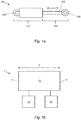
- FIG. 1a shows an example linear actuator 100 which may be tested by an example apparatus according to the present invention.
- the linear actuator 100 comprises a first part 101 which is moveably connected to a second part 102.
- the first part 101 comprises a first mounting feature 104 for connecting the actuator to, e.g., a fixed structure capable of reacting the loads generated by operation of the actuator 100.
- the second part 102 comprises an extendible arm 103 which can extend and retract in the direction shown by the block arrow, and a second mounting feature 105. If the first mounting feature 104 is attached to a fixed structure, the second mounting feature 105 will be mounted to a moveable structure, movement of which is to be actuated by the linear actuator 100.
- the first part 101 may comprise or be connected to a drive mechanism (not shown) such as a hydraulic cylinder, which is arranged to drive extension of the extendible arm 103.
- a drive mechanism such as a hydraulic cylinder, which is arranged to drive extension of the extendible arm 103.
- the linear actuator 101 may include a safety mode to by-pass the hydraulic operation of the actuator, even when experiencing a load acting to extend or retract the arm.
- the linear actuator 101 may comprise a state detection mechanism to detect a current state of extension of the extendible arm 103 (which is equivalent to a current relative position of the first and second mounting features 104, 105, and thus a current relative position of the structures to which the first and second mounting features 104, 105 are mounted).
- the linear actuator may be any type of linear actuator which is configured to exert an actuation force in an actuation direction by movement of a first part of the linear actuator relative to a second part of the linear actuator.
- the linear actuator 100 may be configured to exert a force in the range 10 ton to 20 ton.
- the linear actuator may be configured to exert a force of at least 15 ton.
- the linear actuator may be configured to actuate a flight control surface of an aircraft.
- Figure 1b shows a generalized example of an apparatus 1 for in-situ testing of a linear actuator, e.g. the linear actuator 100 of Figure 1a .
- the example apparatus 1 comprise a test device 10, a test actuator 13, and a measurement device 14.
- the test device 10 comprises a first surface 11 which is configured to contact the first part 101 of the linear actuator 100 during operation of the apparatus 1, and a second surface 12 configured to contact the second part 102 of the linear actuator during operation of the apparatus 1.
- the second surface 12 is moveable relative to the first surface 11 to alter a distance D between the first surface 11 and the second surface 12.
- Relative movement of the first and second surfaces 11, 12 may be enabled, for example, by the test device comprising two parts connected by one or more extending arms, or by the test device having a telescopic construction.
- the test device 10 may have any suitable construction which permits relative movement of the first and second surfaces 11, 12.
- the configuration of the first surface 11 may be arranged to match the configuration of a surface on the first part 101 of the actuator 100 contacted by the first surface 11 during operation of the apparatus 1.
- the first surface 11 may include features such as recesses and/or protrusions which cooperate with corresponding protrusions and/or recesses on a surface of the first part 101 of the actuator 100, such that there is continuous contact between the first surface 11 and the first part 101 of the actuator across the whole area of the first surface 11. Such continuous contact may advantageously enable the loads generated by the apparatus 1 to be passed to the first part 101 of the actuator 100 without risk of damaging the first part 101.
- the configuration of the second surface 12 may be arranged to match the configuration of a surface on the second part 102 of the actuator 100 contacted by the second surface 102 during operation of the actuator 100.
- the test actuator 13 is configured to exert a test force in a direction opposite to the actuation direction of the linear actuator 100 when the apparatus 1 is in use to test the linear actuator 100.
- the test actuator 13 may be configured to exert a test force in the range 1 ton to 10 ton.
- the test actuator 13 may be configured to exert a test force in the range 5 ton to 7 ton.
- the test force is to drive movement of the second surface 12 away from the first surface 11.
- the test actuator is configured to exert the force according to at least one predetermined parameter.
- the at least one predetermined parameter can include one or more of: a magnitude of the test force; a direction of the test force; a time period during which the test force is continuously exerted.
- a predetermined magnitude of the test force may be, for example, 5 ton.
- the predetermined magnitude may be determined based on the nature of the actuator to be tested. For example, the predetermined magnitude may be determined to be similar to or greater than a load expected to be experienced by the linear actuator to be tested during normal operation of that linear actuator.
- An aircraft spoiler actuator may typically experience suction loads of up to 5 ton, so a test force for testing such an actuator may have a magnitude of 5 ton or more.
- a predetermined time period during which the test force is continuously exerted may be in the range 5 minutes to 30 minutes.
- a predetermined time period during which the test force is continuously exerted may be at least 15 minutes.
- the predetermined time period may be determined based on the nature of the actuator to be tested. The predetermined time period may be determined such that if, during operation of the apparatus to test the linear actuator 100, the distance between the first and second surfaces of the test device changes during the predetermined time period, the operational effectiveness of the linear actuator 5 is deemed to be unacceptable, whereas if a distance change were to occurs after the predetermined time period has elapsed (assuming the test force continued to be exerted), the operational effectiveness of the linear actuator 100 would be deemed to be acceptable.
- the test actuator 13 may be partly or fully integrated with the test device 10.
- the test actuator 13 may comprise any suitable type of linear actuator known in the art, such as a hydraulic actuator.
- the measurement device 14 is for detecting a change in the distance between the first surface 11 and the second surface 12.
- the measurement device 14 may be configured to detect such a change, or may be configured to enable an operator of the apparatus 1 to detect such a change (e.g. by displaying information which enables the operator to detect such a change).
- the measurement device 14 may be configured to detect such a change by measuring a parameter relating to a distance between the first surface 11 and the second surface 12. In some such examples the measurement device 14 detects whether the measured parameter exceeds a predetermined threshold. If the test actuator 13 is configured to exert the test force continuously for a time period, the measurement device may be configured to continuously measure the parameter during the time period, and to determine a time at which the measured parameter exceeds the predetermined threshold. If the test actuator 13 is configured to exert the test force continuously for a predetermined time period, the measurement device may be configured to measure the parameter at the end of the predetermined time period.
- the measured parameter may be any one of:
- the measurement device 14 may detect a change in the distance between the first surface 11 and the second surface 12 by detecting a change in the measured parameter. For example, the measurement device 14 may be configured to compare a first measured value of the measured parameter (e.g. obtained at a first time) with a second measured value of the measured parameter (e.g. obtained at a second, later time). If the second measured value is different to the first measured value, or differs by more than a predetermined threshold amount, then the measurement device 14 may be configured to determine that a change in the measured parameter has occurred. The measurement device 14 may be configured to register a positive detection of a change in the distance between the first surface 11 and the second surface 12 if it determines that a change in the measured parameter has occurred.
- the measurement device 14 is partly or fully integrated with the test device 10. In some examples the measurement device 14 is partly or fully integrated with the test actuator 13.
- the measurement device 14 may comprise a state detection mechanism of the test actuator 13, which is configured to detect an extension state of the test actuator 13.
- the measurement device 14 may comprise any suitable distance or position measuring system, which may be configured to measure relative distance or position of parts of the test actuator 13, parts of the test device 10, and/or parts of the linear actuator 100 that is being tested.
- the measurement device 14 may be relatively complex, for example including a controller configured to receive and process measured values.
- the measurement device 14 may be extremely simple.
- a simple measurement device 14 could comprise, for example, a scale (e.g. a ruler) arranged adjacent to the test device 10 to enable an operator to visually determine the distance between the first and second surfaces 11, 12.
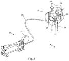
- FIG. 2 shows a particular example of an apparatus 2 according to the invention.
- the apparatus 2 comprises a test device 20, connected to a test actuator 23 and a measurement device 24.
- the test device 20 comprises a first surface 21 which is configured to contact the first part 101 of the linear actuator 100 being tested, during operation of the apparatus 2, and a second surface 22 configured to contact the second part 102 of the linear actuator during operation of the apparatus 2.
- the second surface 22 is moveable relative to the first surface 21 to alter a distance between the first surface 21 and the second surface 22.
- the test device 20, test actuator 23 and measurement device 24 may have any or all of the features of the corresponding components of the apparatus 1 described above.
- the test device 20 comprises two separable components: a load reaction component 3b and a force generation component 3a.
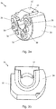
- Figure 3a shows the force generation component 3a in isolation
- Figure 3b shows the load reaction component 3b in isolation.
- the first surface 21 is comprised in the load reaction component 3b and the second surface 22 is comprised in the force generation component 3a.
- the force generation component 21 and the load reaction component 22 are configured to be arranged on the linear actuator 100 such that they abut each other, and such that the force generation component 21 may exert a force on the load reaction component 22 to drive the first and second surfaces 21 and 22 apart.
- the particular example apparatus 2 is configured to test a linear actuator which comprises an extending arm (such as the example linear actuator 100).
- the test device 20 is configured to enclose a cross-section of the extending arm during operation of the apparatus 1 to test the linear actuator.
- the test device 20 when in an operational configuration (as shown in Figure 6 ), has a bore 26 which is shaped to receive the extending arm of the linear actuator to be tested.
- the shape and size of the bore 26 may match the cross-sectional shape and size of the extending arm.
- the force generating component 3a comprises a main part 33, which is approximately U-shaped such that it can be slotted on to the extending arm of the actuator, and a clamp part 32 which is attached to the main part 33 when the main part 33 is in place on the extending arm, to hold the force generating component 3a in place on the extending arm.
- the clamp part includes holes 34 (only one is visible), which enable the clamp part 32 to be fixed to the main part 33 by bolts (screws) 39 (shown in Figure 2 ).
- the load reaction component 3b comprises a main part 38 and a clamp part 37.
- the bore 26 is formed partly by the main part of each component 3a, 3b, and partly by the clamp part of each component 3a, 3b.
- each component 3a, 3b may be configured such that attaching the clamp part to the main part has the effect of fixing the component in place on the extending arm (e.g. due to friction between the component and the extending arm), such that relative movement of the component and the extending arm is prevented.
- the load reaction component 3b is configured to react a maximum actuation force exertable by the linear actuator.
- the load reaction component 3b may thereby function as a safety collar, to prevent the actuator (that is, the actuator which is being tested) from fully retracting during the testing process.
- the load reaction component 3b may be configured to contact one or more selected regions on the second part 105 of the actuator 100.
- the second surface 22 may be configured to contact one or more selected regions on the second part 105 of the actuator 100.
- the selected regions may be selected to prevent or reduce the risk of damage occurring to the second part 105 of the actuator due to a load exerted on it by the test device 20.
- the load generation component 3a comprises one or more extendible members 36, which are connected to the test actuator 23 such that the test actuator 23 can drive extension of the one or more extendible members 36.
- the extendible members 36 comprise three extendible rods arranged to extend from a surface of the main part 33 of the load generation component 3a which is opposite to the first surface 21 and which abuts the load reaction component 3b during operation of the apparatus 2.
- the extendible members 36 are in contact with the load reaction component 3b such that loads may be transmitted from the load generation component 3a to the load reaction component 3b via the extendible members 36.
- extension of the extendible members 36 increases the distance between the first surface 21 and the second surface 22.
- the load generation component 3a may further comprise one or more load transfer features for transferring a load to the load generation component 3a from the load reaction component 3b.
- the load generation component 3a comprises three load transfer features 35 in the form of button interfaces.
- any other suitable type of load transfer feature could alternatively be used.
- the load generation component 3a further comprises an optional rotation prevention mechanism in the form of a locking pin 27 (which in the particular example comprises a ball lock pin) and a lanyard 28.
- the locking pin 27 prevents rotation (relative to an actuator on which the load generation component 3a is arranged) of the force generation component item 3a and the lanyard 28 secures the locking pin 27.
- any other suitable mechanism for preventing rotation of the load generation component 3a could be used.
- the test actuator 23 is configured to drive extension of the one or more extendible members 36.
- the test actuator 23 is a hand-operated hydraulic actuator, which is connected to the extendible members 36 by a hydraulic-fluid-filled tube 25.
- the measurement device 24 of the apparatus 2 is comprised in the test actuator 23, in the form of a pressure gauge integrated with the hydraulic actuator. The pressure value indicated by the pressure gauge correlates with the degree of extension of the extendible members 36, and therefore with the distance between the first and second surfaces 21, 22 of the test device 20.
- an operator of the apparatus 20 may therefore detect a change in the distance between the first and second surfaces 21, 22 by observing the pressure values indicated by the pressure gauge (with a drop in the hydraulic pressure indicating an increase in the distance between the first and second surfaces 21, 22).
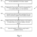
- Figure 4 is a flow chart that implements an example of a method 4 of testing of a linear actuator in-situ. Although the method 4 is described primarily with reference to the particular example apparatus 2, the method 4 may be performed using any apparatus according to the invention and the apparatus components referred to may have any of the features described above in relation to the example apparatus 1 or the example apparatus 2.
- the method 4 may be used to test any linear actuator which is configured to exert an actuation force in an actuation direction by movement of a first part of the linear actuator relative to a second part of the linear actuator.
- the method can be performed with the actuator in its normal operating environment.
- the actuator being tested is an aircraft flight control surface actuator
- the method 4 can be performed in the environment of the aircraft wing, with the actuator remaining connected to the flight control surface and to the wing structure.
- a test device of the apparatus is provided on a linear actuator.
- the test device is provided on the linear actuator such that, in an activated configuration of the linear actuator, the first surface of the test device contacts the first part of the linear actuator and the second surface of the test device contacts the second part of the linear actuator.
- the linear actuator may be put into a maintenance mode before the test device is provided on the linear actuator, e.g. by inserting a maintenance key into the linear actuator.
- the linear actuator may be manually extended such that it is not in a fully retracted configuration before the test device is provided on the linear actuator.
- the linear actuator may be manually retracted as far as possible when the test device has been provided on the linear actuator.
- providing the test device 20 on a linear actuator comprises mounting the load reaction component 3b on the linear actuator by placing the main part 38 of the load reaction component 3b around the extending arm, sliding the main part 38 along the extending arm until the second surface 22 abuts a corresponding surface on the second part of the actuator (such sliding may not be necessary if the main part 38 can be placed in abutment with the second part 52 straight away), and then fixing the clamping part 37 to the main part 38 to fix the load reaction component 3b in place on the extending arm such that relative movement between the load reaction component 3b and the second part of the actuator is prevented.
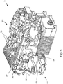
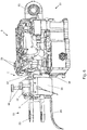
- Figures 5 and 6 show an example linear actuator 5 during a process of providing the test device 20 on the linear actuator 5.
- the linear actuator 5 is for actuating an aircraft spoiler.
- the linear actuator 5 comprises a first part 51, a second part 52, and an extending arm 54 which may have any of the features of the corresponding components of the actuator 100 described above.
- the first part 51 comprises a first mounting feature 53
- the second part 52 comprises a second mounting feature 55 (visible in Figure 6 ).
- the linear actuator 5 as shown in Figure 5 is in a maintenance mode and has been manually put in a partially extended configuration.
- the load reaction component 3b has been mounted on the extending arm 54 of the linear actuator 5, but the force generation component 3a has not yet been mounted on the linear actuator 5.
- the configuration of the load reaction component 3b enables it to fit between the various structures of the second part 52 of the actuator 5, so as to contact a selected structure of the second part 52 that is suitable for reacting the loads generated by the apparatus 2 during a testing process.
- providing the test device 20 on a linear actuator 5 further comprises mounting the force generation component 3a on the linear actuator 5.
- the force generation component 3a may be mounted on the linear actuator 5 after the load reaction component 3b has been mounted on the linear actuator 5.
- the force generation component 3a can be mounted on the linear actuator 5 by placing the main part 33 of the force generating component 3a around the extending arm 54, sliding the main part 33 along the extending arm 54 until the first surface 21 abuts a corresponding surface on the first part 51 of the actuator 5 (such sliding may not be necessary if the main part 33 can be placed in abutment with the first part 51 straight away), and then fixing the clamping part 32 to the main part 33 to fix the force generating component 3a in place on the extending arm 54 such that relative movement between the force generating component 3a and the first part 51 of the actuator 5 is prevented.
- the linear actuator 5 is manually retracted until the force generating component 3a abuts the load reaction component 3b.
- Figure 6 shows the linear actuator 5 after the force generating component 3a has been mounted on the linear actuator, but before the linear actuator 5 has been manually retracted to bring the force generating component 3a into abutment with the load reaction component 3b.
- the linear actuator is operated to exert the actuation force on the test device.
- the actuation force is to reduce the distance between the first part of the linear actuator and the second part of the linear actuator, such that the actuation force compresses the test device.
- Operating the linear actuator to exert the actuation force on the test device may comprise activating a locking mechanism of the linear actuator (that is, a mechanism to hold the linear actuator in a selected state of extension).
- the linear actuator may be changed from the maintenance mode to an operational mode in order to perform block 402, e.g. by removing the maintenance key.
- the linear actuator 5 is a hydraulic actuator and operating the linear actuator 5 to exert the actuation force comprises pressurizing a hydraulic circuit of the linear actuator 5.
- the actuation force exerted by the example linear actuator 5 is 15 ton.
- the linear actuator 5 has an anti-extension locking mechanism, so this mechanism is activated and the hydraulic circuit is depressurized.
- the test device is operated to exert a predetermined test force in a direction opposite to the actuation direction.
- the test force is to increase the distance between the first surface and the second surface of the test device.
- the test force may have any or all of the features described above in relation to the apparatus 1 or the apparatus 2.
- Operating the test device to exert a predetermined test force may comprise activating or operating a test actuator connected to or comprised in the test device.
- the predetermined test force may have a predetermined magnitude and/or direction.
- Operating the test device to exert a predetermined test force may comprise operating the test device to continuously exert the test force for a predetermined time period.
- operating the test device 20 to exert a predetermined test force comprises manually pressurizing a hydraulic circuit comprising the test actuator 23 and the extendible members 36.
- the hydraulic circuit is pressurized to a suitable pressure such that the extendible members exert a test force of 5 ton on the reaction component 3b.
- the test force acts to increase the distance between the first surface 21 and the second surface 22 of the test device 20, and thereby to increase the distance between the first and second parts 51, 52 of the linear actuator 5.
- the hydraulic circuit is maintained in a pressurized state for a predetermined time period of 15 minutes, such that the test force is exerted continuously during the predetermined time period.
- a change in the distance between the first surface and the second surface of the test device is detected.
- Detecting a change in the distance between the first surface and the second surface may be performed in any of the manners described above in relation to the example apparatus 1 or the example apparatus 2.
- detecting a change in the distance between the first and second surfaces may comprise measuring a parameter relating to the distance between the first and second surfaces.
- a parameter relating to the distance between the first and second surfaces may be monitored over a time period.
- Block 404 may be performed at least partly automatically, e.g. by a controller comprised in the apparatus. Alternatively, block 404 may be performed manually, by an operator of the apparatus.
- a change in the distance between the first and second surfaces 21, 22 of the test device 20 is detected by an operator of the apparatus 2 monitoring the pressure in the hydraulic circuit (using the pressure gauge 24 comprised in the test actuator 23) during the time period for which the hydraulic circuit is maintained in a pressurized state.
- a drop in the pressure in the hydraulic circuit indicates an increase in the distance between the first and second surfaces 21, 22 of the test device 20, and therefore an increase in the distance between the first and second parts 51, 52 of the linear actuator 5. If any such distance increase occurs during the time period for which the test force is continuously exerted, it indicates that the linear actuator 5 (in particular, a locking mechanism of the linear actuator 5) is not operating at full effectiveness.
- the method 4 may optionally comprise a further block 405, in which it is determined whether a detected distance change meets a predefined criterion.
- the predefined criterion may be defined such that if a detected change meets the predefined criterion, the operational effectiveness of the linear actuator is unacceptable, and if the detected change does not meet the predefined criterion, the operational effectiveness of the linear actuator is acceptable.
- the predefined criterion may comprise, for example, one or more of: a threshold (e.g. minimum or maximum) time taken for a detected distance change to occur, a threshold (e.g. minimum or maximum) magnitude of a detected distance change; a threshold (e.g.
- Block 405 may, in some examples, be performed automatically (e.g. by a controller of the apparatus). In other examples block 405 may be performed manually by an operator of the apparatus.
- determining whether a detected distance change meets a predefined criterion comprises an operator of the apparatus 2 determining whether a change in the hydraulic circuit pressure has occurred before a threshold maximum time has elapsed, and if such a change has occurred, determining whether a corresponding distance change is greater than or equal to a threshold minimum distance change.
- the threshold maximum time in that example, is equal to the duration of the test period.
- the threshold minimum distance change in the particular example, is 2 mm. Other threshold values may be used in other applications. In general, threshold values will be selected in dependence on the nature of the actuator being tested.
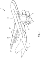
- Figure 7 shows a schematic top view of an example of an aircraft 7 according to the invention, which comprises a fuselage 71 and a pair of wings 72.
- Each wing 72 is provided with multiple flight control surfaces, including a plurality of spoilers 73.
- Each of the spoilers 73 is actuated by a linear actuator (not visible), as are various ones of the other flight control surfaces.
- Each linear actuator may have any or all of the features of the linear actuators 100, 5, described above.
- the aircraft 7 further comprises an apparatus (not visible) for in-situ testing of the linear actuators.
- the apparatus may have any or all of the features of the apparatus 1, 2, described above.
- a test device of the apparatus is mounted on one of the linear actuators such that in an activated configuration of the linear actuator a first surface of the test device contacts a first part of the linear actuator and a second surface of the test device, which is moveable relative to the second surface of the test device in the actuation direction, contacts a second part of the linear actuator which is moveable relative to the first part.
Landscapes
- Engineering & Computer Science (AREA)
- Physics & Mathematics (AREA)
- General Physics & Mathematics (AREA)
- Aviation & Aerospace Engineering (AREA)
- Fluid Mechanics (AREA)
- Mechanical Engineering (AREA)
- General Engineering & Computer Science (AREA)
- Manufacturing & Machinery (AREA)
- Transportation (AREA)
- Automation & Control Theory (AREA)
- Investigating Strength Of Materials By Application Of Mechanical Stress (AREA)
- Testing Of Devices, Machine Parts, Or Other Structures Thereof (AREA)
Claims (14)
- Apparat (1, 2) zum Prüfen eines linearen Aktuators (100) vor Ort, der eingerichtet ist, eine Betätigungskraft durch Bewegung eines ersten Teils (101) des linearen Aktuators relativ zu einem zweiten Teil (102) des linearen Aktuators in eine Betätigungsrichtung auszuüben, wobei die Vorrichtung Folgendes umfasst:eine Prüfvorrichtung (10, 20), umfassend eine erste Oberfläche (11, 21), die eingerichtet ist, das erste Teil des linearen Aktuators während des Betriebs des Apparates zu kontaktieren, und eine zweite Oberfläche (12, 22), die eingerichtet ist, das zweite Teil des linearen Aktuators während des Betriebs des Apparates zu kontaktieren, wobei die zweite Oberfläche relativ zu der ersten Oberfläche beweglich ist, um eine Entfernung zwischen der ersten Oberfläche und der zweiten Oberfläche zu verändern;einen Prüfaktuator (13, 23), der eingerichtet ist, eine Prüfkraft in eine Richtung auszuüben, die der Betätigungsrichtung entgegengesetzt ist, wenn der Apparat in Betrieb ist, um den linearen Aktuator zu prüfen, wobei die Prüfkraft dazu dient, eine Bewegung der zweiten Oberfläche weg von der ersten Oberfläche anzutreiben; undeine Messvorrichtung (14, 24) zum Detektieren einer Veränderung der Entfernung zwischen der ersten Oberfläche und der zweiten Oberfläche.
- Apparat (1) nach Anspruch 1, wobei der lineare Aktuator (100) einen ausziehbaren Arm (103) umfasst und wobei die Prüfvorrichtung (10) eingerichtet ist, einen Querschnitt des ausziehbaren Arms während eines Betriebs des Apparates zum Prüfen des linearen Aktuators zu umschließen.
- Apparat (1, 2) nach Anspruch 1 oder 2, wobei die Prüfvorrichtung (10, 20) eine Lastreaktionskomponente (3b) und eine Krafterzeugungskomponente (3a) umfasst und wobei die erste Oberfläche (11, 21) in der Lastreaktionskomponente enthalten ist und die zweite Oberfläche (12, 22) in der Krafterzeugungskomponente enthalten ist und wobei gegebenenfalls die Lastreaktionskomponente eingerichtet ist, auf eine maximale Betätigungskraft zu reagieren, die durch den linearen Aktuator (100) ausgeübt werden kann.
- Apparat (1, 2) nach Anspruch 3, wobei die Krafterzeugungskomponente (3a) ein oder mehrere ausziehbare Glieder (36) umfasst, die mit dem Prüfaktuator (13, 23) verbunden sind, wobei das eine oder die mehreren ausziehbaren Glieder derartig mit der Lastreaktionskomponente (3b) in Kontakt stehen, dass Lasten aus der Krafterzeugungskomponente über das eine oder die mehreren ausziehbaren Glieder an die Lastreaktionskomponente übertragen werden können, und derartig eingerichtet sind, dass Ausziehen des einen oder der mehreren ausziehbaren Glieder die Entfernung zwischen der ersten Oberfläche (11, 21) und der zweiten Oberfläche (12, 22) erhöht, und wobei der Prüfaktuator eingerichtet ist, ein Ausziehen des einen oder der mehreren ausziehbaren Glieder anzutreiben.
- Apparat (1, 2) nach einem der vorhergehenden Ansprüche, wobei der Prüfaktuator (13, 23) eingerichtet ist, die Prüfkraft gemäß mindestens einem vorgegebenen Parameter auszuüben, wobei der mindestens eine vorgegebene Parameter ein oder mehrere Elemente der folgenden umfasst:eine Größenordnung der Prüfkraft;eine Richtung der Prüfkraft;eine Zeitspanne, während der die Prüfkraft kontinuierlich ausgeübt wird.
- Apparat (1, 2) nach einem der vorhergehenden Ansprüche, wobei die Messvorrichtung (14, 24) eingerichtet ist, einen Parameter zu messen, der eine Entfernung zwischen der ersten Oberfläche (11, 21) und der zweiten Oberfläche (12, 22) betrifft, und gegebenenfalls eingerichtet ist, zu detektieren, ob der gemessene Parameter eine vorbestimmte Schwelle überschreitet.
- Apparat (1, 2) nach Anspruch 6, wobei der Prüfaktuator (13, 23) eingerichtet ist, die Prüfkraft kontinuierlich für eine Zeitspanne auszuüben und entweder:die Messvorrichtung (14, 24) eingerichtet ist, den Parameter während der Zeitspanne kontinuierlich zu messen, und wobei die Messvorrichtung weiterhin eingerichtet ist, eine Zeit zu bestimmen, bei welcher der gemessene Parameter die vorbestimmte Schwelle überschreitet; oderdie Messvorrichtung eingerichtet ist, den Parameter am Ende der vorgegebenen Zeitspanne zu messen.
- Apparat (1, 2) nach Anspruch 6 oder 7, wobei der Parameter einer der folgenden ist:Entfernung zwischen der ersten Oberfläche (11, 21) und der zweiten Oberfläche (12, 22);Entfernung zwischen einem ersten ausgewählten Punkt auf der Prüfvorrichtung (10, 20) und einem zweiten ausgewählten Punkt auf der Prüfvorrichtung;Entfernung zwischen einem ausgewählten Punkt auf dem ersten Teil (101) des linearen Aktuators und einem ausgewählten Punkt auf dem zweiten Teil (102) des linearen Aktuators;Grad des Ausziehens des einen oder der mehreren ausziehbaren Glieder (36);Position eines ausgewählten Punkts auf dem linearen Aktuator;Position eines ausgewählten Punkts auf der Prüfvorrichtung;Position einer Komponente des Prüfaktuators.
- Apparat (1, 2) nach einem der Ansprüche 1 bis 8 in Verbindung mit einem linearen Aktuator (100);
wobei der lineare Aktuator ein erstes Teil (101) umfasst, das mit einem zweiten Teil (102) beweglich verbunden ist, und eingerichtet ist, durch Bewegung des ersten Teils relativ zu dem zweiten Teil eine Betätigungskraft in eine Betätigungsrichtung auszuüben; und
wobei der Apparat zum Prüfen des linearen Aktuators vor Ort dient. - Apparat (1, 2) und linearer Aktuator (100) nach Anspruch 9, wobei die Betätigungskraft dazu dient, die Entfernung zwischen dem ersten Teil (101) des linearen Aktuators und dem zweiten Teil (102) des linearen Aktuators zu reduzieren, so dass die Betätigungskraft die Prüfvorrichtung (10, 20) komprimiert.
- Apparat (1, 2) und linearer Aktuator (100) nach Anspruch 9 oder 10, wobei der lineare Aktuator eingerichtet ist, eine Flugleitfläche (73) eines Flugzeugs (7) zu betätigen, und wobei das erste (101) oder das zweite (102) Teil des linearen Aktuators mit einer festen Struktur eines Flugzeugs verbunden ist und das andere des ersten oder des zweiten Teils des linearen Aktuators mit der Flugleitfläche verbunden ist.
- Flugzeug (7), umfassend den Apparat (1, 2) und den linearen Aktuator (100) nach einem der Ansprüche 9 bis 11.
- Verfahren (4) zum Prüfen eines linearen Aktuators vor Ort, wobei der lineare Aktuator eingerichtet ist, eine Betätigungskraft durch Bewegung eines ersten Teils des linearen Aktuators relativ zu einem zweiten Teil des linearen Aktuators in eine Betätigungsrichtung auszuüben, das Verfahren Folgendes umfassend:Bereitstellen (401) einer Prüfvorrichtung auf dem linearen Aktuator, so dass in einer aktivierten Konfiguration des linearen Aktuators eine erste Oberfläche der Prüfvorrichtung das erste Teil des linearen Aktuators kontaktiert und eine zweite Oberfläche der Prüfvorrichtung das zweite Teil des linearen Aktuators kontaktiert;Betreiben (402) des linearen Aktuators, um die Betätigungskraft auf die Prüfvorrichtung auszuüben;Betreiben (403) der Prüfvorrichtung, um eine vorgegebene Prüfkraft in eine Richtung anzuwenden, die der Betätigungsrichtung entgegengesetzt ist, wobei die Prüfkraft dazu dient, die Entfernung zwischen der ersten Oberfläche und der zweiten Oberfläche zu erhöhen; undDetektieren (404) einer Veränderung der Entfernung zwischen der ersten Oberfläche und der zweiten Oberfläche.
- Verfahren (4) nach Anspruch 13, weiterhin umfassend Bestimmen (405), ob eine detektierte Veränderung ein vordefiniertes Kriterium erfüllt, wobei das vordefinierte Kriterium eines der folgenden umfasst:eine minimale Entfernungsveränderung während einer vorgegebenen Zeitspanne; undeine maximale Zeit, um eine vorgegebene Entfernungsveränderung zu erreichen.
Applications Claiming Priority (1)
| Application Number | Priority Date | Filing Date | Title |
|---|---|---|---|
| GB1620529.6A GB2557273A (en) | 2016-12-02 | 2016-12-02 | Actuator testing |
Publications (2)
| Publication Number | Publication Date |
|---|---|
| EP3330185A1 EP3330185A1 (de) | 2018-06-06 |
| EP3330185B1 true EP3330185B1 (de) | 2019-10-02 |
Family
ID=58159541
Family Applications (1)
| Application Number | Title | Priority Date | Filing Date |
|---|---|---|---|
| EP17203484.5A Active EP3330185B1 (de) | 2016-12-02 | 2017-11-24 | Aktuatorprüfung |
Country Status (5)
| Country | Link |
|---|---|
| US (1) | US10481047B2 (de) |
| EP (1) | EP3330185B1 (de) |
| CN (1) | CN108168876B (de) |
| ES (1) | ES2762111T3 (de) |
| GB (1) | GB2557273A (de) |
Families Citing this family (2)
| Publication number | Priority date | Publication date | Assignee | Title |
|---|---|---|---|---|
| FI130012B (en) | 2018-08-29 | 2022-12-30 | Ponsse Oyj | Determination of a condition of a structural part in a working machine |
| CN115072002A (zh) * | 2022-08-02 | 2022-09-20 | 哈尔滨理工大学 | 多功能扰流板试验台架 |
Family Cites Families (16)
| Publication number | Priority date | Publication date | Assignee | Title |
|---|---|---|---|---|
| US3229510A (en) * | 1962-11-23 | 1966-01-18 | Lockheed Aircraft Corp | Testing apparatus for ball screws and ball-driven actuators |
| US6578425B2 (en) * | 2001-05-29 | 2003-06-17 | Honeywell Inc. | Apparatus and method for verifying the dynamic stiffness capability of hydraulic servo actuators |
| DE102005018593A1 (de) * | 2005-04-21 | 2006-10-26 | Siemens Ag | Vorrichtung zum Prüfen eines Aktors |
| US7607611B2 (en) * | 2005-05-11 | 2009-10-27 | Honeywell International Inc. | Flight control surface actuation system with redundantly configured and lockable actuator assemblies |
| US20060255207A1 (en) * | 2005-05-11 | 2006-11-16 | Honeywell International, Inc. | Flight control surface actuation system with redundantly configured actuator assemblies |
| US7641145B2 (en) * | 2006-11-21 | 2010-01-05 | Eaton Corporation | Apparatus for moving a control surface |
| US8080772B2 (en) * | 2007-11-02 | 2011-12-20 | Honeywell International Inc. | Modular, harnessless electromechanical actuation system assembly |
| FR2966124B1 (fr) * | 2010-10-18 | 2013-08-09 | Sagem Defense Securite | Systeme de deplacement motorise d'un element mobile, procede de pilotage d'un tel systeme et procede de test d'un tel systeme |
| US9086125B2 (en) * | 2013-03-15 | 2015-07-21 | Moog Inc. | Rotary actuator |
| ES2920755T3 (es) * | 2013-06-21 | 2022-08-09 | Massachusetts Materials Tech Llc | Aparato de ensayo de rayado y métodos de uso del mismo |
| JP6011875B2 (ja) * | 2013-07-08 | 2016-10-19 | Smc株式会社 | アクチュエータの異常検出システム |
| CN103499454B (zh) * | 2013-09-03 | 2016-02-24 | 北京摩诘创新科技股份有限公司 | 电动缸性能测试装置 |
| CN205036952U (zh) * | 2013-11-25 | 2016-02-17 | 费希尔控制国际公司 | 使用电子阀致动器诊断阀的装置 |
| NO20140477A1 (no) * | 2014-04-11 | 2015-10-12 | Mera As | System og fremgangsmåte for statusovervåking av et hydraulikksystem på stedet |
| CN105298988B (zh) * | 2015-11-13 | 2018-08-21 | 湖南省产商品质量监督检验研究院 | 液压缸内泄漏测试装置及方法 |
| CN105927617B (zh) * | 2016-06-12 | 2017-12-12 | 广州飞机维修工程有限公司 | 一种飞机大型液压作动筒通用测试平台 |
-
2016
- 2016-12-02 GB GB1620529.6A patent/GB2557273A/en not_active Withdrawn
-
2017
- 2017-11-24 ES ES17203484T patent/ES2762111T3/es active Active
- 2017-11-24 EP EP17203484.5A patent/EP3330185B1/de active Active
- 2017-11-29 US US15/825,747 patent/US10481047B2/en active Active
- 2017-12-04 CN CN201711261154.6A patent/CN108168876B/zh active Active
Non-Patent Citations (1)
| Title |
|---|
| None * |
Also Published As
| Publication number | Publication date |
|---|---|
| EP3330185A1 (de) | 2018-06-06 |
| ES2762111T3 (es) | 2020-05-22 |
| GB2557273A (en) | 2018-06-20 |
| GB201620529D0 (en) | 2017-01-18 |
| US20180156696A1 (en) | 2018-06-07 |
| CN108168876A (zh) | 2018-06-15 |
| US10481047B2 (en) | 2019-11-19 |
| CN108168876B (zh) | 2021-05-18 |
Similar Documents
| Publication | Publication Date | Title |
|---|---|---|
| EP1917188B1 (de) | Landebelastungsüberwachungsvorrichtung für flugzeugfahrwerk | |
| US7983854B2 (en) | Method and apparatus for monitoring a structure | |
| EP3609781B1 (de) | Flugzeugeinfahrverriegelung | |
| EP3404395B1 (de) | Testverfahren und testvorrichtung für flugstellglied-prüfvorrichtung | |
| US11345487B2 (en) | Method for testing operation of an arresting unit for locking a foldable wing tip portion in an extended position | |
| CA2743250C (en) | Load indicator | |
| CA2919342C (en) | Check device for flight actuator primary load path failure detection device | |
| US8702034B2 (en) | Test device for the detection of the recovery effort by a secondary flight ordering actuator, and associated test method | |
| EP3575221A1 (de) | System zur erkennung der integrität eines verriegelungssystems eines fahrgestells im eingefahrenen zustand | |
| US10481047B2 (en) | Apparatus and method for testing a linear acuator | |
| WO2015153731A1 (en) | System and method for health monitoring of hydraulic systems | |
| EP3037347B1 (de) | Verfahren zur Ermittlung eines Zustands einer Komponente in einem Hochauftriebssystem eines Flugzeugs | |
| DK201200737A (en) | Electronic combined load weak link | |
| CN103068675B (zh) | 用于飞行器起落架的销轴承装置 | |
| KR101680090B1 (ko) | 복합재료 구조물의 접촉부 피로시험 평가 방법 | |
| CN111846277A (zh) | 配装有用于检测其减震器触底的装置的飞行器起落架 | |
| EP3339165B1 (de) | Flügelvorflügelaktuatortrennungserkennung | |
| EP3081481B1 (de) | Prüfvorrichtung für eine vorrichtung zur fehlererkennung des primären lastpfades eines flugaktuators | |
| EP3162500A1 (de) | Verfahren zum herstellen einer aktuatoranordnungskomponente und verfahren zur überprüfung einer oberflächenbeschichtung | |
| GB2490282A (en) | Load indicator | |
| GB2490283A (en) | Load indicator |
Legal Events
| Date | Code | Title | Description |
|---|---|---|---|
| PUAI | Public reference made under article 153(3) epc to a published international application that has entered the european phase |
Free format text: ORIGINAL CODE: 0009012 |
|
| STAA | Information on the status of an ep patent application or granted ep patent |
Free format text: STATUS: THE APPLICATION HAS BEEN PUBLISHED |
|
| AK | Designated contracting states |
Kind code of ref document: A1 Designated state(s): AL AT BE BG CH CY CZ DE DK EE ES FI FR GB GR HR HU IE IS IT LI LT LU LV MC MK MT NL NO PL PT RO RS SE SI SK SM TR |
|
| AX | Request for extension of the european patent |
Extension state: BA ME |
|
| STAA | Information on the status of an ep patent application or granted ep patent |
Free format text: STATUS: REQUEST FOR EXAMINATION WAS MADE |
|
| 17P | Request for examination filed |
Effective date: 20181024 |
|
| RBV | Designated contracting states (corrected) |
Designated state(s): AL AT BE BG CH CY CZ DE DK EE ES FI FR GB GR HR HU IE IS IT LI LT LU LV MC MK MT NL NO PL PT RO RS SE SI SK SM TR |
|
| GRAP | Despatch of communication of intention to grant a patent |
Free format text: ORIGINAL CODE: EPIDOSNIGR1 |
|
| STAA | Information on the status of an ep patent application or granted ep patent |
Free format text: STATUS: GRANT OF PATENT IS INTENDED |
|
| INTG | Intention to grant announced |
Effective date: 20190510 |
|
| GRAS | Grant fee paid |
Free format text: ORIGINAL CODE: EPIDOSNIGR3 |
|
| GRAA | (expected) grant |
Free format text: ORIGINAL CODE: 0009210 |
|
| STAA | Information on the status of an ep patent application or granted ep patent |
Free format text: STATUS: THE PATENT HAS BEEN GRANTED |
|
| AK | Designated contracting states |
Kind code of ref document: B1 Designated state(s): AL AT BE BG CH CY CZ DE DK EE ES FI FR GB GR HR HU IE IS IT LI LT LU LV MC MK MT NL NO PL PT RO RS SE SI SK SM TR |
|
| REG | Reference to a national code |
Ref country code: GB Ref legal event code: FG4D |
|
| REG | Reference to a national code |
Ref country code: CH Ref legal event code: EP Ref country code: AT Ref legal event code: REF Ref document number: 1185913 Country of ref document: AT Kind code of ref document: T Effective date: 20191015 |
|
| REG | Reference to a national code |
Ref country code: DE Ref legal event code: R096 Ref document number: 602017007464 Country of ref document: DE |
|
| REG | Reference to a national code |
Ref country code: IE Ref legal event code: FG4D |
|
| REG | Reference to a national code |
Ref country code: NL Ref legal event code: MP Effective date: 20191002 |
|
| REG | Reference to a national code |
Ref country code: LT Ref legal event code: MG4D |
|
| REG | Reference to a national code |
Ref country code: AT Ref legal event code: MK05 Ref document number: 1185913 Country of ref document: AT Kind code of ref document: T Effective date: 20191002 |
|
| PG25 | Lapsed in a contracting state [announced via postgrant information from national office to epo] |
Ref country code: LV Free format text: LAPSE BECAUSE OF FAILURE TO SUBMIT A TRANSLATION OF THE DESCRIPTION OR TO PAY THE FEE WITHIN THE PRESCRIBED TIME-LIMIT Effective date: 20191002 Ref country code: AT Free format text: LAPSE BECAUSE OF FAILURE TO SUBMIT A TRANSLATION OF THE DESCRIPTION OR TO PAY THE FEE WITHIN THE PRESCRIBED TIME-LIMIT Effective date: 20191002 Ref country code: PL Free format text: LAPSE BECAUSE OF FAILURE TO SUBMIT A TRANSLATION OF THE DESCRIPTION OR TO PAY THE FEE WITHIN THE PRESCRIBED TIME-LIMIT Effective date: 20191002 Ref country code: NL Free format text: LAPSE BECAUSE OF FAILURE TO SUBMIT A TRANSLATION OF THE DESCRIPTION OR TO PAY THE FEE WITHIN THE PRESCRIBED TIME-LIMIT Effective date: 20191002 Ref country code: LT Free format text: LAPSE BECAUSE OF FAILURE TO SUBMIT A TRANSLATION OF THE DESCRIPTION OR TO PAY THE FEE WITHIN THE PRESCRIBED TIME-LIMIT Effective date: 20191002 Ref country code: GR Free format text: LAPSE BECAUSE OF FAILURE TO SUBMIT A TRANSLATION OF THE DESCRIPTION OR TO PAY THE FEE WITHIN THE PRESCRIBED TIME-LIMIT Effective date: 20200103 Ref country code: NO Free format text: LAPSE BECAUSE OF FAILURE TO SUBMIT A TRANSLATION OF THE DESCRIPTION OR TO PAY THE FEE WITHIN THE PRESCRIBED TIME-LIMIT Effective date: 20200102 Ref country code: SE Free format text: LAPSE BECAUSE OF FAILURE TO SUBMIT A TRANSLATION OF THE DESCRIPTION OR TO PAY THE FEE WITHIN THE PRESCRIBED TIME-LIMIT Effective date: 20191002 Ref country code: PT Free format text: LAPSE BECAUSE OF FAILURE TO SUBMIT A TRANSLATION OF THE DESCRIPTION OR TO PAY THE FEE WITHIN THE PRESCRIBED TIME-LIMIT Effective date: 20200203 Ref country code: FI Free format text: LAPSE BECAUSE OF FAILURE TO SUBMIT A TRANSLATION OF THE DESCRIPTION OR TO PAY THE FEE WITHIN THE PRESCRIBED TIME-LIMIT Effective date: 20191002 Ref country code: BG Free format text: LAPSE BECAUSE OF FAILURE TO SUBMIT A TRANSLATION OF THE DESCRIPTION OR TO PAY THE FEE WITHIN THE PRESCRIBED TIME-LIMIT Effective date: 20200102 |
|
| REG | Reference to a national code |
Ref country code: ES Ref legal event code: FG2A Ref document number: 2762111 Country of ref document: ES Kind code of ref document: T3 Effective date: 20200522 |
|
| PG25 | Lapsed in a contracting state [announced via postgrant information from national office to epo] |
Ref country code: RS Free format text: LAPSE BECAUSE OF FAILURE TO SUBMIT A TRANSLATION OF THE DESCRIPTION OR TO PAY THE FEE WITHIN THE PRESCRIBED TIME-LIMIT Effective date: 20191002 Ref country code: CZ Free format text: LAPSE BECAUSE OF FAILURE TO SUBMIT A TRANSLATION OF THE DESCRIPTION OR TO PAY THE FEE WITHIN THE PRESCRIBED TIME-LIMIT Effective date: 20191002 Ref country code: IS Free format text: LAPSE BECAUSE OF FAILURE TO SUBMIT A TRANSLATION OF THE DESCRIPTION OR TO PAY THE FEE WITHIN THE PRESCRIBED TIME-LIMIT Effective date: 20200224 Ref country code: HR Free format text: LAPSE BECAUSE OF FAILURE TO SUBMIT A TRANSLATION OF THE DESCRIPTION OR TO PAY THE FEE WITHIN THE PRESCRIBED TIME-LIMIT Effective date: 20191002 |
|
| PG25 | Lapsed in a contracting state [announced via postgrant information from national office to epo] |
Ref country code: AL Free format text: LAPSE BECAUSE OF FAILURE TO SUBMIT A TRANSLATION OF THE DESCRIPTION OR TO PAY THE FEE WITHIN THE PRESCRIBED TIME-LIMIT Effective date: 20191002 |
|
| REG | Reference to a national code |
Ref country code: DE Ref legal event code: R097 Ref document number: 602017007464 Country of ref document: DE |
|
| PG2D | Information on lapse in contracting state deleted |
Ref country code: IS |
|
| PG25 | Lapsed in a contracting state [announced via postgrant information from national office to epo] |
Ref country code: MC Free format text: LAPSE BECAUSE OF FAILURE TO SUBMIT A TRANSLATION OF THE DESCRIPTION OR TO PAY THE FEE WITHIN THE PRESCRIBED TIME-LIMIT Effective date: 20191002 Ref country code: DK Free format text: LAPSE BECAUSE OF FAILURE TO SUBMIT A TRANSLATION OF THE DESCRIPTION OR TO PAY THE FEE WITHIN THE PRESCRIBED TIME-LIMIT Effective date: 20191002 Ref country code: EE Free format text: LAPSE BECAUSE OF FAILURE TO SUBMIT A TRANSLATION OF THE DESCRIPTION OR TO PAY THE FEE WITHIN THE PRESCRIBED TIME-LIMIT Effective date: 20191002 Ref country code: RO Free format text: LAPSE BECAUSE OF FAILURE TO SUBMIT A TRANSLATION OF THE DESCRIPTION OR TO PAY THE FEE WITHIN THE PRESCRIBED TIME-LIMIT Effective date: 20191002 Ref country code: LU Free format text: LAPSE BECAUSE OF NON-PAYMENT OF DUE FEES Effective date: 20191124 Ref country code: IS Free format text: LAPSE BECAUSE OF FAILURE TO SUBMIT A TRANSLATION OF THE DESCRIPTION OR TO PAY THE FEE WITHIN THE PRESCRIBED TIME-LIMIT Effective date: 20200202 |
|
| PLBE | No opposition filed within time limit |
Free format text: ORIGINAL CODE: 0009261 |
|
| STAA | Information on the status of an ep patent application or granted ep patent |
Free format text: STATUS: NO OPPOSITION FILED WITHIN TIME LIMIT |
|
| REG | Reference to a national code |
Ref country code: BE Ref legal event code: MM Effective date: 20191130 |
|
| PG25 | Lapsed in a contracting state [announced via postgrant information from national office to epo] |
Ref country code: SM Free format text: LAPSE BECAUSE OF FAILURE TO SUBMIT A TRANSLATION OF THE DESCRIPTION OR TO PAY THE FEE WITHIN THE PRESCRIBED TIME-LIMIT Effective date: 20191002 Ref country code: IT Free format text: LAPSE BECAUSE OF FAILURE TO SUBMIT A TRANSLATION OF THE DESCRIPTION OR TO PAY THE FEE WITHIN THE PRESCRIBED TIME-LIMIT Effective date: 20191002 Ref country code: SK Free format text: LAPSE BECAUSE OF FAILURE TO SUBMIT A TRANSLATION OF THE DESCRIPTION OR TO PAY THE FEE WITHIN THE PRESCRIBED TIME-LIMIT Effective date: 20191002 |
|
| 26N | No opposition filed |
Effective date: 20200703 |
|
| PG25 | Lapsed in a contracting state [announced via postgrant information from national office to epo] |
Ref country code: IE Free format text: LAPSE BECAUSE OF NON-PAYMENT OF DUE FEES Effective date: 20191124 |
|
| PG25 | Lapsed in a contracting state [announced via postgrant information from national office to epo] |
Ref country code: SI Free format text: LAPSE BECAUSE OF FAILURE TO SUBMIT A TRANSLATION OF THE DESCRIPTION OR TO PAY THE FEE WITHIN THE PRESCRIBED TIME-LIMIT Effective date: 20191002 Ref country code: BE Free format text: LAPSE BECAUSE OF NON-PAYMENT OF DUE FEES Effective date: 20191130 |
|
| PG25 | Lapsed in a contracting state [announced via postgrant information from national office to epo] |
Ref country code: CY Free format text: LAPSE BECAUSE OF FAILURE TO SUBMIT A TRANSLATION OF THE DESCRIPTION OR TO PAY THE FEE WITHIN THE PRESCRIBED TIME-LIMIT Effective date: 20191002 |
|
| REG | Reference to a national code |
Ref country code: CH Ref legal event code: PL |
|
| PG25 | Lapsed in a contracting state [announced via postgrant information from national office to epo] |
Ref country code: MT Free format text: LAPSE BECAUSE OF FAILURE TO SUBMIT A TRANSLATION OF THE DESCRIPTION OR TO PAY THE FEE WITHIN THE PRESCRIBED TIME-LIMIT Effective date: 20191002 Ref country code: HU Free format text: LAPSE BECAUSE OF FAILURE TO SUBMIT A TRANSLATION OF THE DESCRIPTION OR TO PAY THE FEE WITHIN THE PRESCRIBED TIME-LIMIT; INVALID AB INITIO Effective date: 20171124 |
|
| PG25 | Lapsed in a contracting state [announced via postgrant information from national office to epo] |
Ref country code: CH Free format text: LAPSE BECAUSE OF NON-PAYMENT OF DUE FEES Effective date: 20201130 Ref country code: LI Free format text: LAPSE BECAUSE OF NON-PAYMENT OF DUE FEES Effective date: 20201130 |
|
| PG25 | Lapsed in a contracting state [announced via postgrant information from national office to epo] |
Ref country code: TR Free format text: LAPSE BECAUSE OF FAILURE TO SUBMIT A TRANSLATION OF THE DESCRIPTION OR TO PAY THE FEE WITHIN THE PRESCRIBED TIME-LIMIT Effective date: 20191002 |
|
| PG25 | Lapsed in a contracting state [announced via postgrant information from national office to epo] |
Ref country code: MK Free format text: LAPSE BECAUSE OF FAILURE TO SUBMIT A TRANSLATION OF THE DESCRIPTION OR TO PAY THE FEE WITHIN THE PRESCRIBED TIME-LIMIT Effective date: 20191002 |
|
| PGFP | Annual fee paid to national office [announced via postgrant information from national office to epo] |
Ref country code: ES Payment date: 20240129 Year of fee payment: 7 |
|
| REG | Reference to a national code |
Ref country code: ES Ref legal event code: FD2A Effective date: 20260107 |
|
| PGFP | Annual fee paid to national office [announced via postgrant information from national office to epo] |
Ref country code: DE Payment date: 20251119 Year of fee payment: 9 |
|
| PGFP | Annual fee paid to national office [announced via postgrant information from national office to epo] |
Ref country code: GB Payment date: 20251121 Year of fee payment: 9 |
|
| PGFP | Annual fee paid to national office [announced via postgrant information from national office to epo] |
Ref country code: FR Payment date: 20251126 Year of fee payment: 9 |
|
| PG25 | Lapsed in a contracting state [announced via postgrant information from national office to epo] |
Ref country code: ES Free format text: LAPSE BECAUSE OF NON-PAYMENT OF DUE FEES Effective date: 20241125 |