EP3330140B1 - Système régénératif pneumatique hybride - Google Patents
Système régénératif pneumatique hybride Download PDFInfo
- Publication number
- EP3330140B1 EP3330140B1 EP17001919.4A EP17001919A EP3330140B1 EP 3330140 B1 EP3330140 B1 EP 3330140B1 EP 17001919 A EP17001919 A EP 17001919A EP 3330140 B1 EP3330140 B1 EP 3330140B1
- Authority
- EP
- European Patent Office
- Prior art keywords
- pneumatic
- air
- variable
- regenerative system
- motorized vehicle
- Prior art date
- Legal status (The legal status is an assumption and is not a legal conclusion. Google has not performed a legal analysis and makes no representation as to the accuracy of the status listed.)
- Active
Links
- 230000001172 regenerating effect Effects 0.000 title claims description 66
- 238000012546 transfer Methods 0.000 claims description 58
- 230000007246 mechanism Effects 0.000 claims description 38
- 239000012530 fluid Substances 0.000 claims description 10
- 230000005540 biological transmission Effects 0.000 claims description 7
- 238000004891 communication Methods 0.000 claims description 5
- 230000008878 coupling Effects 0.000 claims description 2
- 238000010168 coupling process Methods 0.000 claims description 2
- 238000005859 coupling reaction Methods 0.000 claims description 2
- 239000003570 air Substances 0.000 description 151
- 230000001133 acceleration Effects 0.000 description 25
- 238000006073 displacement reaction Methods 0.000 description 7
- 238000002485 combustion reaction Methods 0.000 description 6
- 230000033001 locomotion Effects 0.000 description 5
- 230000006835 compression Effects 0.000 description 4
- 238000007906 compression Methods 0.000 description 4
- 238000004146 energy storage Methods 0.000 description 4
- 230000004913 activation Effects 0.000 description 3
- 230000006870 function Effects 0.000 description 3
- ATUOYWHBWRKTHZ-UHFFFAOYSA-N Propane Chemical compound CCC ATUOYWHBWRKTHZ-UHFFFAOYSA-N 0.000 description 2
- 238000013459 approach Methods 0.000 description 2
- 230000003416 augmentation Effects 0.000 description 2
- 230000001276 controlling effect Effects 0.000 description 2
- 238000010586 diagram Methods 0.000 description 2
- 239000000446 fuel Substances 0.000 description 2
- 238000005259 measurement Methods 0.000 description 2
- 238000000034 method Methods 0.000 description 2
- 238000011084 recovery Methods 0.000 description 2
- 230000009467 reduction Effects 0.000 description 2
- 230000001105 regulatory effect Effects 0.000 description 2
- OKTJSMMVPCPJKN-UHFFFAOYSA-N Carbon Chemical compound [C] OKTJSMMVPCPJKN-UHFFFAOYSA-N 0.000 description 1
- 230000003213 activating effect Effects 0.000 description 1
- 230000004075 alteration Effects 0.000 description 1
- 239000012080 ambient air Substances 0.000 description 1
- 230000000740 bleeding effect Effects 0.000 description 1
- 238000009530 blood pressure measurement Methods 0.000 description 1
- 238000009529 body temperature measurement Methods 0.000 description 1
- 229910052799 carbon Inorganic materials 0.000 description 1
- 238000010276 construction Methods 0.000 description 1
- 230000006735 deficit Effects 0.000 description 1
- 230000000881 depressing effect Effects 0.000 description 1
- 239000002283 diesel fuel Substances 0.000 description 1
- 238000005516 engineering process Methods 0.000 description 1
- 230000007613 environmental effect Effects 0.000 description 1
- 238000001914 filtration Methods 0.000 description 1
- 239000002803 fossil fuel Substances 0.000 description 1
- 239000003502 gasoline Substances 0.000 description 1
- 238000010438 heat treatment Methods 0.000 description 1
- 238000012423 maintenance Methods 0.000 description 1
- 238000012986 modification Methods 0.000 description 1
- 230000004048 modification Effects 0.000 description 1
- 239000013618 particulate matter Substances 0.000 description 1
- 238000012545 processing Methods 0.000 description 1
- 239000001294 propane Substances 0.000 description 1
- 238000004064 recycling Methods 0.000 description 1
- 239000013589 supplement Substances 0.000 description 1
Images


Classifications
-
- B—PERFORMING OPERATIONS; TRANSPORTING
- B60—VEHICLES IN GENERAL
- B60T—VEHICLE BRAKE CONTROL SYSTEMS OR PARTS THEREOF; BRAKE CONTROL SYSTEMS OR PARTS THEREOF, IN GENERAL; ARRANGEMENT OF BRAKING ELEMENTS ON VEHICLES IN GENERAL; PORTABLE DEVICES FOR PREVENTING UNWANTED MOVEMENT OF VEHICLES; VEHICLE MODIFICATIONS TO FACILITATE COOLING OF BRAKES
- B60T1/00—Arrangements of braking elements, i.e. of those parts where braking effect occurs specially for vehicles
- B60T1/02—Arrangements of braking elements, i.e. of those parts where braking effect occurs specially for vehicles acting by retarding wheels
- B60T1/10—Arrangements of braking elements, i.e. of those parts where braking effect occurs specially for vehicles acting by retarding wheels by utilising wheel movement for accumulating energy, e.g. driving air compressors
-
- F—MECHANICAL ENGINEERING; LIGHTING; HEATING; WEAPONS; BLASTING
- F15—FLUID-PRESSURE ACTUATORS; HYDRAULICS OR PNEUMATICS IN GENERAL
- F15B—SYSTEMS ACTING BY MEANS OF FLUIDS IN GENERAL; FLUID-PRESSURE ACTUATORS, e.g. SERVOMOTORS; DETAILS OF FLUID-PRESSURE SYSTEMS, NOT OTHERWISE PROVIDED FOR
- F15B21/00—Common features of fluid actuator systems; Fluid-pressure actuator systems or details thereof, not covered by any other group of this subclass
- F15B21/14—Energy-recuperation means
-
- B—PERFORMING OPERATIONS; TRANSPORTING
- B60—VEHICLES IN GENERAL
- B60K—ARRANGEMENT OR MOUNTING OF PROPULSION UNITS OR OF TRANSMISSIONS IN VEHICLES; ARRANGEMENT OR MOUNTING OF PLURAL DIVERSE PRIME-MOVERS IN VEHICLES; AUXILIARY DRIVES FOR VEHICLES; INSTRUMENTATION OR DASHBOARDS FOR VEHICLES; ARRANGEMENTS IN CONNECTION WITH COOLING, AIR INTAKE, GAS EXHAUST OR FUEL SUPPLY OF PROPULSION UNITS IN VEHICLES
- B60K6/00—Arrangement or mounting of plural diverse prime-movers for mutual or common propulsion, e.g. hybrid propulsion systems comprising electric motors and internal combustion engines ; Control systems therefor, i.e. systems controlling two or more prime movers, or controlling one of these prime movers and any of the transmission, drive or drive units Informative references: mechanical gearings with secondary electric drive F16H3/72; arrangements for handling mechanical energy structurally associated with the dynamo-electric machine H02K7/00; machines comprising structurally interrelated motor and generator parts H02K51/00; dynamo-electric machines not otherwise provided for in H02K see H02K99/00
- B60K6/08—Prime-movers comprising combustion engines and mechanical or fluid energy storing means
- B60K6/12—Prime-movers comprising combustion engines and mechanical or fluid energy storing means by means of a chargeable fluidic accumulator
-
- B—PERFORMING OPERATIONS; TRANSPORTING
- B60—VEHICLES IN GENERAL
- B60T—VEHICLE BRAKE CONTROL SYSTEMS OR PARTS THEREOF; BRAKE CONTROL SYSTEMS OR PARTS THEREOF, IN GENERAL; ARRANGEMENT OF BRAKING ELEMENTS ON VEHICLES IN GENERAL; PORTABLE DEVICES FOR PREVENTING UNWANTED MOVEMENT OF VEHICLES; VEHICLE MODIFICATIONS TO FACILITATE COOLING OF BRAKES
- B60T1/00—Arrangements of braking elements, i.e. of those parts where braking effect occurs specially for vehicles
- B60T1/02—Arrangements of braking elements, i.e. of those parts where braking effect occurs specially for vehicles acting by retarding wheels
- B60T1/08—Arrangements of braking elements, i.e. of those parts where braking effect occurs specially for vehicles acting by retarding wheels using fluid or powdered medium
- B60T1/093—Arrangements of braking elements, i.e. of those parts where braking effect occurs specially for vehicles acting by retarding wheels using fluid or powdered medium in hydrostatic, i.e. positive displacement, retarders
-
- F—MECHANICAL ENGINEERING; LIGHTING; HEATING; WEAPONS; BLASTING
- F04—POSITIVE - DISPLACEMENT MACHINES FOR LIQUIDS; PUMPS FOR LIQUIDS OR ELASTIC FLUIDS
- F04C—ROTARY-PISTON, OR OSCILLATING-PISTON, POSITIVE-DISPLACEMENT MACHINES FOR LIQUIDS; ROTARY-PISTON, OR OSCILLATING-PISTON, POSITIVE-DISPLACEMENT PUMPS
- F04C18/00—Rotary-piston pumps specially adapted for elastic fluids
- F04C18/08—Rotary-piston pumps specially adapted for elastic fluids of intermeshing-engagement type, i.e. with engagement of co-operating members similar to that of toothed gearing
- F04C18/12—Rotary-piston pumps specially adapted for elastic fluids of intermeshing-engagement type, i.e. with engagement of co-operating members similar to that of toothed gearing of other than internal-axis type
- F04C18/14—Rotary-piston pumps specially adapted for elastic fluids of intermeshing-engagement type, i.e. with engagement of co-operating members similar to that of toothed gearing of other than internal-axis type with toothed rotary pistons
- F04C18/16—Rotary-piston pumps specially adapted for elastic fluids of intermeshing-engagement type, i.e. with engagement of co-operating members similar to that of toothed gearing of other than internal-axis type with toothed rotary pistons with helical teeth, e.g. chevron-shaped, screw type
-
- F—MECHANICAL ENGINEERING; LIGHTING; HEATING; WEAPONS; BLASTING
- F15—FLUID-PRESSURE ACTUATORS; HYDRAULICS OR PNEUMATICS IN GENERAL
- F15B—SYSTEMS ACTING BY MEANS OF FLUIDS IN GENERAL; FLUID-PRESSURE ACTUATORS, e.g. SERVOMOTORS; DETAILS OF FLUID-PRESSURE SYSTEMS, NOT OTHERWISE PROVIDED FOR
- F15B1/00—Installations or systems with accumulators; Supply reservoir or sump assemblies
- F15B1/02—Installations or systems with accumulators
- F15B1/027—Installations or systems with accumulators having accumulator charging devices
-
- F—MECHANICAL ENGINEERING; LIGHTING; HEATING; WEAPONS; BLASTING
- F15—FLUID-PRESSURE ACTUATORS; HYDRAULICS OR PNEUMATICS IN GENERAL
- F15B—SYSTEMS ACTING BY MEANS OF FLUIDS IN GENERAL; FLUID-PRESSURE ACTUATORS, e.g. SERVOMOTORS; DETAILS OF FLUID-PRESSURE SYSTEMS, NOT OTHERWISE PROVIDED FOR
- F15B11/00—Servomotor systems without provision for follow-up action; Circuits therefor
- F15B11/06—Servomotor systems without provision for follow-up action; Circuits therefor involving features specific to the use of a compressible medium, e.g. air, steam
- F15B11/064—Servomotor systems without provision for follow-up action; Circuits therefor involving features specific to the use of a compressible medium, e.g. air, steam with devices for saving the compressible medium
-
- F—MECHANICAL ENGINEERING; LIGHTING; HEATING; WEAPONS; BLASTING
- F15—FLUID-PRESSURE ACTUATORS; HYDRAULICS OR PNEUMATICS IN GENERAL
- F15B—SYSTEMS ACTING BY MEANS OF FLUIDS IN GENERAL; FLUID-PRESSURE ACTUATORS, e.g. SERVOMOTORS; DETAILS OF FLUID-PRESSURE SYSTEMS, NOT OTHERWISE PROVIDED FOR
- F15B11/00—Servomotor systems without provision for follow-up action; Circuits therefor
- F15B11/08—Servomotor systems without provision for follow-up action; Circuits therefor with only one servomotor
-
- F—MECHANICAL ENGINEERING; LIGHTING; HEATING; WEAPONS; BLASTING
- F15—FLUID-PRESSURE ACTUATORS; HYDRAULICS OR PNEUMATICS IN GENERAL
- F15B—SYSTEMS ACTING BY MEANS OF FLUIDS IN GENERAL; FLUID-PRESSURE ACTUATORS, e.g. SERVOMOTORS; DETAILS OF FLUID-PRESSURE SYSTEMS, NOT OTHERWISE PROVIDED FOR
- F15B2211/00—Circuits for servomotor systems
- F15B2211/70—Output members, e.g. hydraulic motors or cylinders or control therefor
- F15B2211/705—Output members, e.g. hydraulic motors or cylinders or control therefor characterised by the type of output members or actuators
- F15B2211/7058—Rotary output members
Definitions
- the present invention relates to pneumatic-based regenerative systems. More specifically, the present invention relates to a pneumatic-based regenerative system equipped with a variable compression booster compressor, where the variable compression booster compressor configured to modulate the braking torque provided by the pneumatic-based regenerative system.
- Regenerative vehicle power augmentation systems are typically applied to the start/stop cycles of vehicles to improve the overall fuel efficiency of the vehicle.
- a regenerative vehicle power augmentation system captures braking energy, which is otherwise released as heat into the environment, during a braking event of the vehicle, where the captured braking energy is then stored. The stored energy is later used to supplement engine power to assist in acceleration.
- hybrid electric vehicles have achieved commercial success in consumer automotive markets.
- This type of vehicle can improve overall energy efficiency by recapturing energy used by the vehicle's braking system, which is typically released to the environment as wasted energy for conventional (i.e., non-hybrid) vehicles.
- the captured energy is stored as electrical energy in batteries, which can be released to the drive system at appropriate times to reduce the load on the internal combustion engine of the vehicle.
- Certain types of hybrid electric vehicles can achieve economy improvements of 30% or more.
- hybrid electric vehicles have gained popularity for consumer vehicles (e.g., sedans, minivans, SUVs, etc.), such vehicles are limited in their ability to provide desirable fuel economies for larger and heavier vehicles, such as military vehicles, large package transport vehicles, and even railway vehicles.
- the high life-cycle cost associated with required battery replacements (and the resulting carbon footprint associated with disposing or recycling used batteries) as well as the larger and heavier battery that is required for larger and heavier vehicles makes a hybrid electric system undesirable for such larger vehicles.
- the limits in power delivery of battery systems also render the hybrid electric technology undesirable for use with vehicles that are larger and heavier in relation to typical consumer vehicles.
- Vehicles equipped with hybrid hydraulic systems have also been utilized for motorized vehicles, in which a compressed gas is used to pump hydraulic fluid into a hydraulic motor to provide assistance to the combustion engine of the vehicle.
- a compressed gas is used to pump hydraulic fluid into a hydraulic motor to provide assistance to the combustion engine of the vehicle.
- hydraulic fluid leakage there are environmental concerns with such systems, such as hydraulic fluid leakage, as well as economic costs associated with the additional weight and maintenance associated with such systems.
- the finite working volume of incompressible hydraulic fluid limits the speed of the drive circuit (due to viscous losses and heating), and limits the endurance and operating temperature of the system.
- a hybrid pneumatic regenerative system for a motorized vehicle comprises a pneumatic device configured to both draw air from the environment and compress the air for storage, and later, expand the stored high pressure air and release it into the environment.
- the pneumatic device of the present invention is operable as an air compressor and as a pneumatic (air) motor.
- the pneumatic device draws air from the environment, compresses the air, and directs pressurized air to an accumulator during a braking operation of the vehicle, where the pressurized air is stored at a suitable elevated pressure (i.e., a pressure that is above the ambient air pressure or air pressure of the surrounding environment) until it is used.
- the pneumatic device When operating as a pneumatic motor, the pneumatic device draws the pressurized air stored within the accumulator, where it is expanded and used as a working fluid for driving/operating the pneumatic motor.
- the pneumatic device is coupled with a drive shaft of the motorized vehicle to facilitate rotation of the drive shaft to propel the motorized vehicle.
- a main drive mechanism is also coupled to the drive shaft, and the pneumatic device is operable in combination with the main drive mechanism to reduce the energy requirements of the drive mechanism during acceleration of the motorized vehicle.
- the hybrid pneumatic regenerative system of the present invention further includes a variable booster device coupled to the pneumatic device.
- the variable booster device is configured to modulate the braking torque provided by the hybrid pneumatic regenerative system by altering the density of the air entering the pneumatic device prior to the pneumatic device processing the air and delivering the air to the accumulator.
- the hybrid pneumatic regenerative system of the present invention can be utilized with any types, makes and models of motorized vehicles including, without limitation, conventional automobiles (e.g., sedans, SUVs, pick-up trucks, etc.), as well as larger types of vehicles (e.g., heavy duty trucks, military, shipping and other types of industrial vehicles).
- the motorized vehicles include a main drive system (e.g., an internal combustion engine) to power, accelerate and propel the vehicle as well as a braking system to decelerate or stop the vehicle.
- the motorized vehicles are typically types having at least four wheels with at least one front axle and at least one rear axle.
- the present invention is not limited to such types of vehicles, but instead can be implemented for use with any type of vehicle (e.g., a two wheeled vehicle, a three wheeled vehicle, a six wheeled vehicle, etc.) that includes a main drive system as well as a suitable braking system.
- a main drive system such as internal combustion engines, electric motors, etc.
- braking systems e.g., disk braking systems, or any other suitable types of braking systems
- the present invention can be implemented with any such conventional types and/or other types of systems.
- FIG. 1 illustrates a motorized vehicle 100, and more specifically, a front-loading refuse truck, equipped with the hybrid pneumatic regenerative system 200.
- the motorized vehicle 100 includes a plurality of axles 120(1), 120(2), 120(3).
- Each of the axles 120(1)-120(3) includes a pair of wheels 110(1), 110(2), 110(3), respectively.
- the pairs of wheels 110(1)-110(3) are coupled to the ends of each of the plurality of axles 120(1)-120(3), where the each of the pairs of wheels 110(1)-110(3) are configured to support the motorized vehicle 100 on a support surface.
- Figs. 1 illustrates a motorized vehicle 100, and more specifically, a front-loading refuse truck, equipped with the hybrid pneumatic regenerative system 200.
- the motorized vehicle 100 includes a plurality of axles 120(1), 120(2), 120(3).
- Each of the axles 120(1)-120(3) includes a pair of wheels 110(1), 110(2), 110(3), respectively.
- the pairs of wheels 110(1)-110(3)
- the motorized vehicle 100 includes a drive mechanism 130 (e.g., an internal combustion engine) that is operatively coupled a drive shaft 140, which includes a first portion 142 and a second portion 144.
- the drive shaft 140 mechanically couples the drive mechanism 130 to at least one of the axles 120(2) via a gearing mechanism 150 (e.g., a differential).
- the drive mechanism 130 is configured to drive rotation of the at least one axle 120(2) via the drive shaft 140, which, in turn, rotates the pair of wheels 110(2) to propel the motorized vehicle 100 along a support surface.
- Fig. 1 further illustrates a hybrid pneumatic regenerative system 200 mechanically coupled to the second axle 120(2) of the motorized vehicle 100.
- the hybrid pneumatic regenerative system 200 is configured to operate both during a braking event/operation and an acceleration event/operation of the motorized vehicle 100.
- the hybrid pneumatic regenerative system 200 performs two main functions, absorbing the braking energy of the axle 120(2) via the pneumatic device 210, and storing the absorbed braking energy into an energy storage assembly/accumulator 220.
- the hybrid pneumatic regenerative system 200 performs two main functions, releasing the previously absorbed braking energy from the energy storage assembly/accumulator 220, and applying the previously absorbed braking energy to the axle 120(2) via the pneumatic device 210 to drive rotation of the axle 120(2).
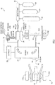
- Fig. 2 illustrates the components of a first embodiment of the hybrid pneumatic regenerative system 200 during a braking event of the motorized vehicle 100
- Fig. 3 illustrates the components of the first embodiment of the hybrid pneumatic regenerative system 200 during an acceleration event of the motorized vehicle 100.
- the hybrid pneumatic regenerative system 200 includes, a pneumatic device 210 and an accumulator 220, a transfer case 230, an electronic control unit (ECU) or controller 240, and a variable boosting device 250.
- the transfer case 230 is coupled to the drive shaft 140. More specifically, the transfer case 230 is disposed between the first portion 142 of the drive shaft 140 and the second portion 144 of the drive shaft 140. The first portion 142 of the drive shaft 140 is coupled to the second portion 144 of the drive shaft 140 within the transfer case 230, such that rotational energy of the first portion 142 of the drive shaft 140 is conveyed to the second portion 144 of the drive shaft 140 during operation of the drive mechanism 130.
- the transfer case 230 includes any suitable number of gears, rotary shafts, etc. that facilitate transfer of rotational and kinetic energy from one rotating shaft or drive member to another, particularly when the shafts/drive members are not aligned coaxially or even in parallel with one another.
- the transfer case 230 is operatively coupled to the gear mechanism 150 of the axle 120(2).
- the transfer case 230 is indirectly coupled to the pair of wheels 110(2) of the axle 120(2).
- the transfer case 230 may contain a continuously variable transmission (CVT).
- the transfer case 230 is also operatively coupled to the pneumatic device 210 and the variable boosting device 250.
- the pneumatic device 210 is a multi-staged pneumatic device that can operate as either a compressor or a pneumatic motor (e.g., a four stage pneumatic device) depending on whether or not the pneumatic device 210 is operating during a braking event or an acceleration event of the motorized vehicle 100.
- the pneumatic device 210 and the variable booster device 250 are in fluid communication. More specifically, air that enters the variable booster device 250 from the environment surrounding the motorized vehicle 100 is eventually delivered to the pneumatic device 210.
- transfer case 230 is mechanically coupled to the axle 120(2) of the motorized vehicle 100, rotation of the pair of wheels 110(2), and thus the axle 120(2), impart motion onto the transfer case 230.
- Motion imparted onto the transfer case 230 by rotation of the axle 120(2) is transferred by the transfer case 230 to both the pneumatic device 210 and the variable booster device 250.
- motion imparted onto the transfer case 230 by rotation of the axle 120(2) causes the transfer case 230 to drive operation of the pneumatic device 210 and the variable booster device 250.
- Figs. 2 and 3 further illustrate that the accumulator, or energy storage apparatus, 220 is coupled to the pneumatic device 210, such that the accumulator 220 is in fluid communication with the pneumatic device 210.
- the accumulator 220 includes three tanks 222, 224, 226.
- the first tank 222 is the largest of the tanks 222, 224, 226, the third tank 226 is the smallest of the tanks 222, 224, 226, and the second tank 224 is smaller than the first tank 222 but larger than the third tank 226.
- the first tank 222 is capable of storing a larger volume of air than the other tanks 224, 226.
- the storage tanks 222, 224, 226 are capable of storing air up to 8,000 psig (about 55.16 MPa) or even greater.
- Other embodiments of the accumulator 220 may contain any number of air storage tanks.
- controller 240 of the hybrid pneumatic regenerative device 200 is logically coupled to at least the transfer case 230 and the variable booster device 250.
- the controller 240 is configured to adjust/control the CVT transmission of the transfer case 230.
- the controller 240 is configured to control the variable booster device 250 and to what amount the variable booster device 250 pressurizes the incoming air.
- the controller 240 is also logically connected with the brake and accelerator actuators of the motorized vehicle 100, such that the controller 240 is capable of determining the braking force or torque requested by the operator for the motorized vehicle 100.
- the controller 240 may also configured to calculate the velocity of the motorized vehicle 100, the rotational speed of the axle 120(2), and the current volume/pressure of the air stored within any of the tanks 222, 224, 226 of the accumulator 220.
- the controller 240 actuates the transfer case 230 to selectively engage with at least the second portion 144 of the drive shaft 140 to receive the power transmitted from the rotation of the axle 120(2).
- the transfer case 230 receives the power from the rotating axle 120(2), motion is imparted onto the inner components of the transfer case 230, such as the CVT transmission.
- the transfer case 230 translates the received power to both the pneumatic device 210 and the variable booster device 250 to operate both the pneumatic device 210 and the variable booster device 250.
- the power translated from the transfer case 230 to the pneumatic device 210 causes the pneumatic device 210 to operate as a compressor and draw air from the environment surrounding the motorized vehicle 100 through variable booster device 250 and into the pneumatic device 210.
- the variable booster device 250 compresses the incoming air to a first pressure state before the air travels into the pneumatic device 210, where it is then further compressed to a second pressure state and stored at a high pressure in the accumulator 220.
- pressurized air refers to air that is at a pressure which is greater than the pressure of air in the ambient or surrounding environment for the motorized vehicle 100.
- variable booster device 250 can be altered to pressurize the air to a desired higher pressure at the first pressure state prior to the air being further compressed by the pneumatic device 210.
- the controller 240 is logically connected to the transfer case 230 and is configured to manage and regulate the CVT of the transfer case 230 to keep both the pneumatic device 210 and the variable booster device 250 operating at an optimal speed.
- the controller 240 calculates the total braking capacity of the hybrid pneumatic drive system 200, activates the hybrid pneumatic drive system 200, and diverts any excess braking energy (not capable of being absorbed by the pneumatic device 210) to a conventional brake system of the motorized vehicle 100.
- the controller 240 Upon activation of the hybrid pneumatic regenerative system 200, the controller 240 further regulates the CVT of the transfer case 230 based on the rotational speed of the axle 120(2) and the calculated braking force to cause the pneumatic device 210 to absorb the kinetic energy of the motorized vehicle 100.
- the pneumatic device 210 draws air from the environment surrounding the motorized vehicle 100 in through the variable booster device 250 and compresses the air.
- the controller 240 regulates the CVT of the transfer case 230 to maintain both the pneumatic device 210 and the variable booster device 250 at as close to optimal speed as possible to dispose the compressed air into the accumulator 220 until the maximum pressure of each of the air tanks 222, 224, 226 of the accumulator 220 is reached.
- the controller 240 also regulates the variable booster device 250 to control the degree and amount of air which the variable booster device 250 pre-pressurizes prior to the air entering the pneumatic device 210.
- the controller 240 can further serve to slow the rotational speed of the axle 120(2) and the wheels 110(2) by regulating and altering the CVT based on the operational loads of the pneumatic device 210 and the calculated braking force magnitude of the motorized vehicle 100.
- the controller 240 in performing this function, may also take into consideration the current pressure of the tanks 222, 224, 226 of the accumulator 220 relative to the maximum pressure of the tanks 222, 224, 226 of the accumulator 220, as well as the current speed or velocity of the motorized vehicle 100.
- the speed or velocity of the motorized vehicle 100 is reduced.
- the conventional brake system e.g., a disk brake system
- the hybrid pneumatic regenerative mechanism 200 utilizes the stored pressurized air disposed within the tanks 222, 224, 226 of the accumulator 220 to operate, or put to work, the pneumatic device 210 to drive rotation of the axle 120(2) via the transfer case 230.
- the pneumatic device 210 operates as an air motor, where the pneumatic device 210 draws in and expands the pressurized air from the accumulator 220 to impart rotation onto the axle 120(2) via the transfer case 230.
- a signal is sent to the controller 240 that is translated to a torque command.
- the pneumatic device 210 is activated via the opening of the tanks 222, 224, 226 of the accumulator 220.
- the pressurized air is transferred from the accumulator 220 to the pneumatic device 210 prior to the start of each cycle of the pneumatic device 210.
- the pneumatic device 210 expands the pressurized air and delivers power to rotate the axle 120(2) via the transfer case 230.
- the pressurized air may be discharged by the pneumatic device 210 to the environment surrounding the motorized vehicle 100.
- the pneumatic device 210 may discharge the air to the environment without the air traveling back through the variable booster device 250. In other embodiments, however, the pneumatic device 210 may discharge the air to the environment, where the air travels back through the variable booster device 250 prior to being discharged to the environment.
- the controller 240 regulates and alters the CVT of the transfer case 230 to enable the power output by the pneumatic device 210 to rotate the axle 120(2) with the optimal rotational speed.
- the drive mechanism 130 may be configured to supply the torque deficit to the axle 120(2).
- the device mechanism 130 and the pneumatic device 210 may be configured to supply power in parallel, or simultaneously, to rotate the axle 120(3).
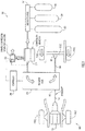
- FIG. 4 illustrated is a detailed schematic diagram of a second exemplary embodiment of a hybrid pneumatic regenerative system 300 in accordance with the present invention.
- the hybrid pneumatic regenerative system 300 may be equipped on the motorized vehicle 100 illustrated in Fig. 1 , where the hybrid pneumatic regenerative system 300 is mechanically coupled to the second axle 120(2) on the motorized vehicle 100 and the pair of wheels 110(2).
- This second embodiment of the hybrid pneumatic regenerative system 300 is shown connected to the drive shaft 140, between the first portion 142 of the drive shaft 140 and the second portion 144 of the drive shaft 140, via the transfer case 302.
- the drive mechanism 130 is connected via the first portion 142 of the drive shaft 140 and transfer case 302 to the second portion 144 of the drive shaft 140.
- the drive mechanism 130 can be an internal combustion engine of any conventional or other suitable type that utilizes a fossil fuel source (e.g., gasoline, diesel fuel, propane, etc.) to power the drive mechanism 130, where the drive mechanism 130 works in any conventional or other suitable manner to rotate the drive shaft 140.
- the drive mechanism 130 can be of any other suitable type (e.g., an electric powered motor) that provides drive power to the drive shaft 140.
- the first portion 142 of the drive shaft 140 from the drive mechanism 130 is coupled to the second portion 144 of the drive shaft 140 within the transfer case 302, such that rotational energy of the first portion 142 of the drive shaft 140 is conveyed to the second portion 144 of the drive shaft 140 during operation of the drive mechanism 130.
- the transfer case 302 includes any suitable number of gears, rotary shafts, etc. that facilitate transfer of rotational and kinetic energy from one rotating shaft or drive member to another, particularly when the shafts/drive members are not aligned coaxially or even in parallel with one another.
- the second portion 144 of the drive shaft 140 couples the transfer case 302 of the pneumatic regenerative system 300 to the axle 120(2) via the gearing mechanism 150 (e.g., differential).
- the pneumatic regenerative system 300 is ultimately coupled to the pair of wheels 110(2) of the motorized vehicle 100.
- Rotation of the drive shaft 140 provides power and rotational energy to the axle 120(2) and the wheels 110(2) to propel the motorized vehicle 100.
- the motorized vehicle 100 can be of any suitable make, model or type, where the motorized vehicle 100 can be propelled utilizing any suitable number of wheels and/or any suitable number of power drive mechanisms that transfer drive power from the drive shaft 140 to one or more wheels or pairs of wheels.
- FIG. 4 is shown as providing power to one pair of wheels 110(2) (e.g., one set of rear wheels of the motorized vehicle 100), it is noted that power can provided to any of the wheels 110(1), 110(2), 110(3) of the motorized vehicle 100 (e.g., front wheel drive, rear wheel drive, all wheel drive, etc.)
- the drive system and a pair of drive wheels 110(2) are schematically shown for the motorized vehicle 100 of Fig. 1 .
- the system is connected to a lower carriage portion or chassis of the motorized vehicle 100.
- the drive system can be connected to the vehicle chassis in a similar manner as a conventional or other type of drive system for a motorized vehicle 100 (e.g., via suitable mounts for components to the chassis).
- the motorized vehicle 100 may include a conventional or main braking system (e.g., disk brakes) that is implemented on any selected number of wheels (e.g., one, two or more) of the motorized vehicle 100 to decelerate or stop the motorized vehicle 100.
- the main braking system is not shown in Figs. 1 or 4 for ease of reference.
- the hybrid pneumatic regenerative system 300 of the present invention includes an air compressor 304 that is coupled with the drive shaft 140 via the transfer case 302, an electromechanical clutch 306, and a continuously variable transmission (CVT) 308.
- the clutch 306, via an electrical actuating mechanism (e.g., a solenoid), is provided to selectively engage and disengage a drive shaft of the compressor 304 connected with the CVT 308 and with the second portion 144 of the drive shaft 140 within the transfer case 302.
- the CVT 308 converts the power of the second portion 144 of the drive shaft 140 to an appropriate drive power for the air compressor 304 (e.g., via suitable gearing mechanisms within the CVT 308).
- variable booster device 316 is coupled to the conduit 310, at a location downstream from the air compressor 304, to compresses the incoming air to a first pressurized state before the air travels into the air compressor 304, where the amount the air is pressurized by the variable booster device 316 can be varied.
- variable booster device 316 is also mechanically coupled to the CVT 308 so that the CVT 308 converts the power of the second portion 144 of the drive shaft 140 to an appropriate drive power for the variable booster device 316 (e.g., via suitable gearing mechanisms within the CVT 308).
- Both the intake screen 312 and air filter 314 provide a suitable filtration of the intake air (e.g., removing particulate matter of selected dimensions from the air) prior to the intake air entering the variable booster device 316 and the compressor 304.
- the hybrid pneumatic regenerative system 300 further includes an accumulator 318 comprising a high pressure tank that receives pressurized air from the compressor 304, via a pressurized air conduit 320.
- a check valve 322 is provided within the air conduit 320 to prevent any backflow of air from the air conduit 320 back to the compressor 304.
- a pressure regulator can be provided within the air conduit 320 to control the pressure and flow of air prior to entry within the accumulator 318.
- the accumulator 318 may also include a relief valve 324 that controls the pressure within the accumulator 318 (e.g., by releasing pressurized air from the accumulator 318 to the external environment when the pressure within the accumulator 318 exceeds an upper limit value).
- the accumulator 318 is depicted in Fig. 4 as a single tank, it is noted that the accumulator 318 can alternatively comprise a plurality of tanks arranged in parallel or in series within the pneumatic regenerative system 300, as depicted for the embodiment illustrated in Figs. 2 and 3 .
- the accumulator 318 is designed to accommodate and store the pressurized air received from the air compressor 304.
- pressurized air refers to air that is at a pressure which is greater than the pressure of air in the ambient or surrounding environment for the motorized vehicle 100.
- the accumulator 318 can store pressurized air at pressures of at least about 500 psig (about 3.447 MPa) or greater for use in operation of the pneumatic regenerative system 300.
- the compressor 304 can provide pressurized air to the accumulator 318, with the accumulator 318 storing pressurized air at pressures as large as about 6,000 psig (about 41.37 MPa) to about 8,000 psig (about 55.16 MPa) or even greater.
- Another pressurized air conduit 326 connects an outlet of the accumulator 318 with an inlet of a pneumatic motor 328. Disposed within the air conduit 326 is an electromechanical valve 330 that is electrically controlled (e.g., via a solenoid actuator) to control the flow of pressurized air from the accumulator 318 to the pneumatic motor 328. A pressure regulator 332 is also provided within the air conduit 326 to control the pressure and flow of pressurized air to the pneumatic motor 328.
- the pneumatic motor 328 receives the pressurized air from the accumulator 318 and allows the air to expand to generate mechanical energy, which rotates an output shaft of the motor 328.
- the output shaft of the pneumatic motor 328 is coupled, via a one-way or sprag clutch 334, to a suitable connection within the transfer case 302 that is also coupled with the second portion 144 of the drive shaft 140.
- the sprag clutch 334 frictionally engages with the connection within the transfer case 302 when the output shaft of the motor 328 rotates in one direction, and the sprag clutch 334 disengages or free wheels with the connection in the transfer case 302 when the output shaft of the motor 328 is stationary.
- the pneumatic motor 328 delivers rotary drive power to the second portion 144 of the drive shaft 140 by expansion of pressurized air received from the accumulator 318.
- the expanded air exits the motor 328 via an exhaust conduit 336 and muffler 338.
- An ECU or controller 340 is provided to control operation of the pneumatic regenerative system 300 by controlling the electromechanical clutch 306 (which couples the compressor 304 to the second portion 144 of the drive shaft 140, via the transfer case 302) and the electromechanical valve 330 (which provides pressurized air flow from the accumulator 318 to the inlet of the pneumatic motor 328).
- the controller 340 is coupled with the clutch 306 and the valve 330, as well as one or more sensors provided within the accumulator 318 and/or at other locations within the pneumatic regenerative system 300.
- one or more pressure sensors as well as any other types of sensors (e.g., temperature sensors) are provided to measure the pressure and/or amount of pressurized air that is stored within the accumulator 318 and/or flowing through the air conduit 326 at any given time.
- a pressure sensor 342 is provided in the air conduit 326 proximate the outlet of the accumulator 318.
- the pneumatic regenerative system 300 can include any other pressure and/or other types of sensors at other locations (e.g., to measure pressure and/or temperature within the accumulator 318).
- the controller 340 is also coupled with the pressure regulator 332 so as to control operation of the regulator 332 in order to further control the pressure and flow of air to the pneumatic motor 338.
- the controller 340 is coupled with the variable booster device 316 so as to control the degree or amount in which the variable booster device 316 pressurizes the air prior to the air entering the compressor 304.
- the controller 340 is coupled with the sensor(s) (represented by sensor 342), regulator 332, clutch 306, valve 330, and variable booster device 316 via any suitable wireless or hardwire connection.
- the controller 340 is coupled (via a wireless or hardwire connection) with the accelerator and brake actuators of the motorized vehicle 100 (represented generally as box 344 in Fig. 1 ).
- One or more suitable position and/or any other types of displacement sensors are connected with the accelerator and brake actuators and coupled with the controller 340 to provide the controller 340 with an indication of the amount of braking force or the acceleration force required during operation (e.g., the braking or acceleration force can be determined as proportionate to the amount or degree of displacement of the brake or acceleration actuator that is pressed by the operator of the motorized vehicle 100).
- the controller 340 includes a processor with suitable logic that facilitates control of the hybrid pneumatic regenerative system 300 based upon the braking and power requirements of the motorized vehicle 100 during operation.
- the controller 340 can also include a memory module to store data acquired from the sensors and/or any other types of information, including control algorithms to be implemented by the processor during operation of the motorized vehicle 100.
- the detailed schematic diagram of the second exemplary embodiment of the hybrid pneumatic regenerative system 300 illustrated in Fig. 4 may be implemented on the motorized vehicle 100 illustrated in Fig. 1 .
- the accumulator 318 of system 300 may be empty or filled to some level (e.g., partially filled or filled to capacity) with pressurized air (e.g., the accumulator 318 may contain some amount of pressurized air that was accumulated during a previous use of the motorized vehicle 100).
- Operation of the pneumatic regenerative system 300 is initiated when an operator starts an ignition for the motorized vehicle 100 to initiate operation of the drive mechanism 130.
- the motorized vehicle 100 proceeds to travel at a selected velocity.
- the controller 340 of the system 300 determines whether to "charge” the accumulator 318 with pressurized air.
- a braking command is initiated by the operator of the motorized vehicle 100 by actuating the brake actuator of the motorized vehicle 100 (shown generally as box 344 in Fig. 4 ).
- the controller 340 which is in communication with the brake actuator sensors, receives the braking command and determines the magnitude of the brake force required (e.g., based upon the amount or degree of displacement of the brake actuator by the operator).
- the controller 340 next determines the brake force capacity that can be provided the system 300.
- the compressor 304 and the variable booster device 316 are activated, by coupling the electromechanical clutch 306 with the second portion 144 of the drive shaft 140 via the transfer case 302, at least some of the rotational power of the second portion 144 of the drive shaft 140 is transferred as kinetic energy, through the connected transfer case 302, clutch 306, and CVT 308, to operate the compressor 304 and the variable booster device 316.
- the transfer of kinetic energy by the transfer case 302, clutch 306, and CVT 308 of the system 300 results in a "drag" on the second portion 144 of the drive shaft 140, which, in turn, imparts that "drag" onto the axle 120(2).
- the controller 340 determines, based upon the amount of pressurized air that is already in the accumulator 318 (e.g., by measuring the pressure and/or any other conditions within the accumulator 318 and/or the conduit 326 via the sensors 342 disposed at such locations) and thus to what extent the compressor 304 and the variable booster device 316 need to operate, the magnitude of the brake force capacity (e.g., the amount of "drag” that can be applied to the second portion 144 of the drive shaft 144) that results from operation of the compressor 304 and the variable booster device 316.
- the magnitude of the brake force capacity e.g., the amount of "drag” that can be applied to the second portion 144 of the drive shaft 14
- the remaining or excess braking force that is required to achieve the required braking force is provided by the main braking system (e.g., a disk brake system) for the motorized vehicle 100.
- the main braking system e.g., a disk brake system
- Control of the amount of force applied by the main braking system can be achieved in any number of conventional or other ways (e.g., for a hydraulic braking system, by controlling the pressure of the hydraulic portion that applies a force to the mechanical/frictional portion of the braking system).
- control logic of the controller 340 may allow operation of the compressor 304 only to the extent that a maximum pressure (P max ) is achieved within the accumulator 318. Operation of the compressor 304 and the variable booster are initiated and maintained during a braking cycle of operation of the motorized vehicle 100 (i.e., based upon a brake command by the operator depressing the brake actuator of the vehicle 100) only to the extent that the measured pressure within the accumulator 318 is no greater than the maximum pressure (P meas ⁇ P max ). In another exemplary embodiment, the controller 340 may continuously operate the compressor 304 and the variable booster device 316 to supply pressurized air to the accumulator 318 during the braking operation.
- the pressure within the accumulator 318 can be controlled so as to not exceed the maximum pressure (P max ) by bleeding air from the accumulator 318 (e.g., via the relieve valve 324) or from each air conduit 326 (e.g., via an electromechanical valve 330 disposed along the air conduit 326 that can be selectively controlled by the controller 340 to bleed air from the system 300 when the pressure approaches P max ).
- the controller 340 After determining the brake force capacity of the pneumatic regenerative system 300, the controller 340 initiates a braking operation for the axle 120(2) of the motorized vehicle 100 by activating the air compressor 304 and variable booster device 316. In particular, the controller 340 activates the clutch 306 so as to couple the drive shaft of the compressor 304 and the variable booster device 316, via the CVT 308, clutch 306 and transfer case 302, with the second portion 144 of the drive shaft 140. The main braking system is also actuated, as necessary (e.g., when it is determined that the required braking force exceeds the braking capacity of pneumatic regenerative system 300).
- the kinetic energy from the rotation of the axle 120(2) and the second portion 144 of the drive shaft 140 is transferred from the transfer case 302 and via the clutch 306 and CVT 308 to the drive shafts of the compressor 304 and the variable booster device 316. This results in pressurized air being supplied to the accumulator 318 and also a deceleration or reduction in velocity of the axle 120(2) of the motorized vehicle 100.
- the controller 340 determines whether a sufficient brake force has been applied to the axle 120(2) of the motorized vehicle 100 as a result of actuation of the compressor 304 and the variable booster device 316 and/or the main braking system of the vehicle 100.
- the axle 120(2) may be separately evaluated to determine if the sufficient brake force has been applied. If the required brake force has been fully applied for the axle 120(2), the compressor 304 and the variable booster device 316 (if still operating) are deactivated along with the main braking system, as necessary, and the braking operation ends.
- the air compressor 304 and the variable booster device 316 are deactivated by decoupling the associated clutch 306 with the second portion 144 of the drive shaft 140.
- the controller 340 monitors the pressure within the accumulator 318. If the pressure within the accumulator 318 is less than the maximum allowed pressure (P meas ⁇ P max ), the controller 340 re-activates or maintains activation of the compressor 304 and the variable booster device 316. If the measured pressure within the accumulator 318 is not less than the maximum allowed pressure, the air compressor 304 and the variable booster device 316 are deactivated. In an alternative embodiment, as noted above, the air compressor 304 can continue to operate during the entire braking operation, where the controller 340 monitors the pressure within the accumulator 318 and bleeds the accumulator 318 as necessary (e.g., when P meas approaches P max ).
- the controller 340 may deactivate the variable booster device 316 prior to deactivating the compressor 304, where the controller 340 may deactivate the variable booster device 316 based on the brake force already applied to the axle 120(2), the total brake force requested, and the pressure within accumulator 318.
- the motorized vehicle 100 is equipped with the hybrid pneumatic regenerative system 300, the energy that would otherwise be lost from decelerating axle 120(2) of the motorized vehicle 100 is recaptured to some extent by the system 300, which pressurizes air and stores the pressurized air within the accumulator 318 for later use during an acceleration event of the motorized vehicle 100.
- the displacement sensor(s) associated with the accelerator actuator provides the command to the controller 340 of the system 300, where the degree of acceleration to be applied by the system 300 is determined by the controller 340 based upon the sensor measurements.
- the controller 340 determines the magnitude of the acceleration force required for the axle 120(2) based upon the displacement sensor information.
- the controller 340 also determines the capacity of the acceleration force that can be provided by the system 300 based upon the known amount of pressurized air within the accumulator 318 (e.g., based upon pressure measurements and any other types of sensor measurements, such as temperature measurements, measured within the accumulator 318 and/or within the air conduit 326).
- the controller 340 activates at least one of the pneumatic motor 328 and the drive mechanism 130 based upon the acceleration force requirements. For example, if it is determined that the pneumatic motor 328 of the system 300 can contribute to the acceleration requirements based upon the amount of pressurized air within the accumulator 318, then the pneumatic motor 328 is activated to drive rotation of the axle 120(2), even in conjunction with the drive mechanism 130 (as explained below in detail). However, if it is determined that there is an insufficient amount of pressurized air necessary to operate the pneumatic motor 328 to meet at least a portion of the acceleration requirements, only the drive mechanism 130 is activated to meet the acceleration requirements.
- the controller 340 activates the pneumatic motor 328 by opening the electromechanical valve 330 to force pressurized air from the accumulator 318 through the air conduit 326 and to the inlet of the pneumatic motor 328.
- the pressure of the air is also regulated by the regulator 332, which is selectively controlled by the controller 340.
- the pressurized air flows through the air conduit 326 to the inlet of the pneumatic motor 328, where it expands within the motor 328 and causes the drive shaft of the motor 328 to rotate.
- the one way or sprag clutch 334 connected with the rotating drive shaft of the pneumatic motor 328 couples, via the transfer case 302, with the second portion 144 of the drive shaft 140, delivering accelerating power to the axle 120(2).
- the expanded air exits the pneumatic motor 328 through the exhaust conduit 336 and muffler 338, where it is vented to the environment surrounding the motorized vehicle 100.
- both the pneumatic motor 328 and the drive mechanism 130 can operate in parallel to provide power to the drive shaft 140 of the vehicle 100.
- both the pneumatic motor 328 and drive mechanism 130 can operate together, where the pneumatic motor 328 ceases operation when the pressurized air supply from the accumulator 318 is sufficiently depleted.
- the system 300 can be designed to operate in series, where the pneumatic motor 328 can be activated first and operated until its energy is depleted or exhausted (i.e., the pressurized air is sufficiently depleted within the accumulator 318), followed by activation of the drive mechanism 130.
- the controller 340 deactivates the pneumatic motor 328 (by closing the associated electromechanical valve 330) when it is determined that the pressurized air supply is sufficiently depleted (e.g., when a measured pressure within the accumulator 318, P meas , is below a minimum or threshold value) and/or when the required acceleration force has been applied to the axle 120(2).
- the system 300 facilitates "charging" of the accumulator 318 with pressurized air during a braking event of the motorized vehicle 100, so as to capture some of the braking energy from the axle 120(2), with subsequent use of the captured energy during an acceleration event of the motorized vehicle 100.
- a continuous cycle of braking and acceleration events when utilizing the motorized vehicle 100 results in a reduction of the energy requirements for the drive mechanism 130 of the motorized vehicle 100.
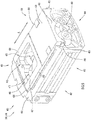
- variable booster device 250, 316 illustrated is an example embodiment of the variable booster device 250, 316 that may be utilized in the first exemplary embodiment of the pneumatic regenerative system 200 and the second exemplary embodiment of the pneumatic regenerative system 300 in accordance with the present invention.
- the variable booster device 250, 316 includes a main body or housing 400 and a sliding plate 420.
- the main body 400 of the variable booster device 250, 316 is substantially rectangular with a top side 401 and an opposite bottom side 402.
- the main body 400 further includes a front end 404, and opposite rear end 405, a first side 406, and a second side 407 opposite the first side 406.
- the top side 401 of the main body 400 includes an opening 410, which provides access to the interior cavity 412 of the main body 400.
- the top side 401 further includes two grooves 414, 416.
- the first groove 414 (not labeled) is disposed on the top side 401 proximate to the first side 406.
- the second groove 416 is disposed on the top side 401 proximate to the second side 407. Both the first groove 414 and the second groove 416 extend through the top side 401 from the front end 404 to a point proximate the rear end 405.
- the plate 420 Slidably disposed on the top side 401, and configured to at least partially cover the opening 410, is a plate 420.
- the plate 420 includes a front end 422 and an opposite rear end 424.
- the plate 420 further includes first and second sides 430, 432, which span between the front end 422 and the rear end 424.
- an aperture 425 is disposed in the rear end 424 and through the plate 420.
- the aperture 425 is disposed in the plate 420 such that the aperture 425 is equidistant from the first side 430 and the second side 432, such that the plate 420 includes a first extension 426 and a second extension 427 that extend along the sides of the aperture 425 proximate to the rear end 424 of the plate 420. Because the plate 420 covers the top side 401 of the main body 400, the opening 410 on the top side 401 of the main body 400 and the aperture 425 of the plate 420 collectively define the outlet 440 of the variable booster device 250, 316.
- the first rail 431 is configured to be slidably received by the first groove 414 of the top side 401 of the main body 400
- the second rail 433 is configured to be slidably received by the second groove 416 of the top side 401 of the main body 400.
- the plate 420 is configured to slide along the top side 401 of the main body 400 along longitudinal plane A, where the rails 431, 433 slide within the grooves 414, 416, respectively.
- sliding the plate 420 along the longitudinal plane A moves the plate 420 with respect to the main body 400 of the variable booster device 250, 316, such that the exposed portion of the opening 410 of the top side 401 of the main body 400 varies.
- sliding the plate 420 along the longitudinal plane A alters the size of the outlet 440 of the variable booster device 250, 316.
- Fig. 5 further illustrates an inlet port 450 disposed on the front end 404 of the main body 400 of the variable booster device 250, 316.
- the inlet port 450 is in fluid communication with the interior cavity 412 and the outlet 440 of the variable booster device 250, 316, such that gas (e.g., air) is configured to travel through the inlet port 450 and into the interior cavity 412 of the main body 400
- gas e.g., air
- the variable booster device 250, 316 is a rotary-screw compressor.
- Rotary-screw compressors are a type of gas compressor that utilizes two meshing helical screw rotors 460, 470 to compress the gas (e.g., air).
- the first screw rotor 460 and the second screw rotor 470 are disposed within the interior cavity 412 of the main body 400 of the variable booster device 250, 316.
- the air enters the variable booster device 250, 316 at the inlet port 450 on the front end 404 of the main body 400 of the variable booster device 250, 316, and moves through the variable booster device 250, 316 along the threads 462, 472 as the screws 460, 470 rotate.
- the first screw rotor 460 includes a plurality of threads 462.
- the first screw rotor 460 is configured to rotate about axis B in a first direction.
- the second screw rotor 470 includes a plurality of threads 472.
- the second screw rotor 470 is configured to rotate about axis C in a second direction, where the second direction is opposite of the first direction.
- the first screw rotor 460 may rotate about axis B in a counterclockwise direction, while the second screw rotor 470 may rotate about axis C in a clockwise direction.
- the threads 462 of the first screw rotor 460 are intermeshed with the threads 472 of the second screw rotor 470.
- the meshing threads 462, 472 of the screw rotors 460, 470 force the gas (e.g., air) through the main body 400 while simultaneously compressing the gas (e.g., air) between the threads 462, 472 and the screw rotors 460, 470.
- the gas e.g., air
- the gas is moved from the inlet port 450 to the outlet 440, where the gas (e.g., air) exits the variable booster device 250, 316 through the outlet 440 formed by the opening 410 on the top side 401 of the main body 400 and the aperture 425 of the sliding plate 420.
- the intermeshed threads 462, 472 compress the gas (e.g., air) that enters through the inlet port 450 until the gas (e.g., air) reaches the outlet 440.
- the gas e.g., air
- the main body 400 of the variable booster device 250, 316 further includes a drive shaft 480 extending from the rear end 405 of the main body 400.
- the drive shaft 480 may be mechanically coupled to one or more of the screw rotors 460, 470 such that rotation of the drive shaft 480 induces rotation of the screw rotors 460, 470.
- the drive shaft 480 may also be operatively coupled to the CVT of the transfer case 230, 302, where rotation of the axle 120(2) of the motorized vehicle 100 induces rotation of the drive shaft 480, and subsequently the screw rotors 460, 470, when the CVT of the transfer case 230, 302 is selectively engaged with the drive shaft 480.
- Figs. 7A and 7B further illustrate the variable booster device 250, 316, where the sliding plate 420 is in the first configuration D ( Fig. 7A ) and the second configuration E ( Fig. 7B ).
- the sliding plate 420 In the first configuration D, the sliding plate 420 is fully retracted, where the front end 422 of the plate 420 extends forward from the front end 404 of the main body 400, while the rear end 424 of the plate 420 is spaced forward from the rear end 405 of the main body 400.
- the sliding plate is fully extended, where the front end 422 of the plate 420 is disposed rearward of the front end 404 of the main body 400, while the rear end 424 of the plate 420 is spaced proximate to the rear end 405 of the main body 400.
- the rear end 424 of the plate 420 is spaced farthest from the rear end 405 of the main body 400 in the first configuration D.
- the plate 420 may be disposed in any number of intermediary configurations between the first configuration D and the second configuration E.
- the plate 420 slides along longitudinal plane A between the first configuration D and the second configuration E.
- the positioning of the sliding plate 420 with respect to the main body 400 locates the aperture 425 over the opening 410 of the main body 400, such that a large portion of the opening 410 of the main body 400 is revealed/exposed.
- the positioning of the sliding plate 420 with respect to the main body locates the aperture 425 over the opening 410 of the main body 400, such that a smaller portion of the opening 410 of the main body 400 is revealed/exposed.
- the outlet 440 which is collectively defined by the overlapping of aperture 425 of the sliding plate 420 with the opening 410 of the main body 400, is larger when the sliding plate 420 is in the first configuration D than when the sliding plate 420 is in the second configuration E.
- the aperture 425 which defines the forward most portion of the outlet 440, is disposed closer to the front end 404 of the main body 400 when the plate 420 is in the first configuration D than when the plate is in the second configuration E.
- gas e.g., air
- gas that enters the variable booster device 250, 316 through the inlet port 450 on the front end 404 of the main body 400 travels a shorter distance within the interior cavity 412 of the main body 400 to reach the outlet 440 when the plate 420 is in the first configuration D than when the plate 420 is in the second configuration E.
- the gas e.g., air
- the gas is compressed more (i.e., the gas is pressurized to a higher pressure) by the screw rotors 460, 470 than when the sliding plate 420 is in the first configuration D.
- the amount that the gas (e.g., air) is compressed increases.
- the gas e.g., air
- the gas is compressed a first amount when the sliding plate 420 is in the first configuration D, and is compressed a second amount when the sliding plate 420 is in the second configuration E, where the second amount is greater than the first amount.
- variable booster device 250, 316 is coupled to the pneumatic device 210 or the air compressor 304, where the variable booster device 250, 316 pressurized the gas (e.g., air) to a first pressurized state prior to the gas (e.g., air) being further pressurized by the pneumatic device 210 or the air compressor 304.
- gas e.g., air
- variable booster device 250, 316 the more the gas (e.g., air) is compressed/pressurized prior by the variable booster device 250, 316, the greater the amount of braking energy that can be stored within the accumulator 220, 318.
- the sliding plate 420 may be positioned in the first configuration D, the second configuration E, or any of the number of intermediary configurations based on the desired braking torque of the operator of the motorized vehicle 100.
- the variable booster device 250, 316 can modulate the braking torque of the motorized vehicle by changing the density of the air (i.e., varying the pressure and amount of the air processed which is proportional to wheel braking torque) delivered to the subsequent stages of compression.
- the movement of the sliding plate 420 along the longitudinal plane A, and/or the variation of the speed of screws 460 470 by shaft 480 coupled to the CVT of the transfer case 230 provides an alteration of the braking torque, and may be either manually controlled by the operator of the motorized vehicle 100 or automatically controlled by the controller 240, 340 to alter the braking performance of the motorized vehicle 100 for ride comfort and/or maximum power recovery. If the positioning of the sliding plate 420 is configured to be automatically controlled by the controller 240, 340, then the controller 240, 340 may selectively adjust the positioning of the sliding plate 420 based on the magnitude of brake force requested, the amount of pressure disposed within the accumulator 220, 318, and the motorized vehicle speed (including the rotational speed of the axle 120(2).
- the hybrid pneumatic regenerative systems and corresponding methods described above can be utilized with any types, makes or models of motorized vehicles, including on-road vehicles, off-road vehicles, commercial automobiles typically utilized by private consumers, medium to heavy duty military and/or commercial vehicles including, without limitation, medium duty trucks (e.g., refuse trucks, shipping trucks, etc.), buses (e.g., shuttle buses, public transit buses, etc.), construction equipment (e.g., loader, equipment handlers and transporters, etc.), and vehicles with stationary power take-off (PTO) requirements (e.g., utility boom trucks).
- medium duty trucks e.g., refuse trucks, shipping trucks, etc.
- buses e.g., shuttle buses, public transit buses, etc.
- construction equipment e.g., loader, equipment handlers and transporters, etc.
- PTO stationary power take-off
- the system of the present invention does not require an electric battery or hydraulic fluid, which can significantly increase the weight of the vehicle, particularly for medium to heavy duty vehicles.
- the pneumatic drive portion of the system of the present invention is an open system in that the "working fluid" (i.e., air) is obtained (drawn in) from the surrounding environment in which the motorized vehicle is operated and is further exhausted after being used.
Landscapes
- Engineering & Computer Science (AREA)
- Mechanical Engineering (AREA)
- General Engineering & Computer Science (AREA)
- Transportation (AREA)
- Physics & Mathematics (AREA)
- Fluid Mechanics (AREA)
- Chemical & Material Sciences (AREA)
- Combustion & Propulsion (AREA)
- Analytical Chemistry (AREA)
- Arrangement Or Mounting Of Propulsion Units For Vehicles (AREA)
- Regulating Braking Force (AREA)
- Electric Propulsion And Braking For Vehicles (AREA)
Claims (10)
- Système pneumatique régénératif (200, 300) pour un véhicule motorisé (100), comprenant un dispositif de suralimentation variable (250, 316) étant fluidiquement couplé avec un dispositif pneumatique (210) du système pneumatique régénératif (200, 300) et étant utilisable pour mettre sous pression de l'air à un premier état de pression lors d'un événement de freinage du véhicule motorisé (100), le dispositif pneumatique (210) utilisable comme un compresseur d'air lors de l'événement de freinage, où le dispositif pneumatique (210) reçoit l'air du dispositif de suralimentation variable (250, 316) à un premier état de pression et comprime l'air à un deuxième état de pression, le dispositif de suralimentation variable (250, 316) comprenant :un corps principal (400) ayant une entrée (450), une sortie (440), et une cavité intérieure (412), l'entrée (450) et la sortie (440) sont en communication de fluide avec la cavité intérieure (412) ; etun mécanisme de sortie variable (420) couplé au corps principal (400) et recouvrant la sortie (440), le mécanisme de sortie variable (420) étant reconfigurable entre une première configuration, où la sortie (440) est d'une première taille, et une deuxième configuration, où la sortie (440) est d'une deuxième taille, la deuxième taille étant plus petite que la première taille.
- Système pneumatique régénératif (200, 300) selon la revendication 1, dans lequel le dispositif de suralimentation variable (250, 316) est configuré pour comprimer l'air d'une première quantité lorsque le mécanisme de sortie variable (420) est dans la première configuration et comprimer l'air d'une deuxième quantité lorsque le mécanisme de sortie variable (420) est dans la deuxième configuration, la deuxième quantité étant supérieure à la première quantité.
- Système pneumatique régénératif (200, 300) selon la revendication 1, comprenant en outre :un premier rotor à vis hélicoïdale (460, 470) disposé dans la cavité intérieure (412) ; etun deuxième rotor à vis hélicoïdale (460, 470) disposé dans la cavité intérieure (412), dans lequel les première et deuxième vis hélicoïdales sont engrenées l'une avec l'autre.
- Système pneumatique régénératif (200, 300) selon la revendication 3, dans lequel le premier rotor à vis hélicoïdale (460, 470) tourne dans un premier sens autour d'un premier axe longitudinal du premier rotor à vis hélicoïdale (460, 470), et le deuxième rotor à vis hélicoïdale (460, 470) tourne dans un deuxième sens autour d'un deuxième axe longitudinal du deuxième rotor à vis hélicoïdale (460, 470), le deuxième sens étant opposé au premier sens, où la rotation du premier rotor à vis hélicoïdale (460, 470) et du deuxième rotor à vis hélicoïdale (460, 470) comprime l'air dans la cavité intérieure (412) du corps principal (400) du dispositif de suralimentation variable (250, 316).
- Système pneumatique régénératif (200, 300) selon la revendication 3, dans lequel le système pneumatique régénératif (200, 300) est mécaniquement couplé à un essieu (120(2)) du véhicule motorisé (100), le système pneumatique régénératif (200, 300) comprend en outre :
une boîte de transfert (230, 302) couplant le dispositif de suralimentation variable (250, 316) et le dispositif pneumatique (210) à l'essieu (120(2)) du véhicule motorisé (100). - Système pneumatique régénératif (200, 300) selon la revendication 5, dans lequel la boîte de transfert inclut une transmission à variation continue (308).
- Système pneumatique régénératif (200, 300) selon la revendication 6, dans lequel la rotation de l'essieu (120(2)) fait fonctionner le dispositif pneumatique (210) et entraîne la rotation du premier rotor à vis hélicoïdale (460, 470) et du deuxième rotor à vis hélicoïdale (460, 470) du dispositif de suralimentation variable (250, 316) par l'intermédiaire de la transmission à variation continue.
- Système pneumatique régénératif (200, 300) selon la revendication 7, dans lequel le système pneumatique régénératif (200, 300) comprend en outre :
un contrôleur (240, 340) couplé à la boîte de transfert, au dispositif de suralimentation variable (250, 316), et au dispositif pneumatique (210), le contrôleur commandant automatiquement la transmission à variation continue pour optimiser un fonctionnement du moteur pneumatique et une vitesse de rotation du premier rotor à vis hélicoïdale (460, 470) et du deuxième rotor à vis hélicoïdale (460, 470) du dispositif de suralimentation variable (250, 316) lors de l'événement de freinage du véhicule motorisé (100). - Système pneumatique régénératif (200, 300) selon la revendication 8, dans lequel le contrôleur est en outre configuré pour :
modifier automatiquement la configuration du mécanisme de sortie variable (420) du dispositif de suralimentation variable (250, 316) lors de l'événement de freinage du véhicule motorisé (100). - Système pneumatique régénératif (200, 300) selon la revendication 1, dans lequel le mécanisme de sortie variable (420) comprend une plaque couplée coulissante au corps principal (400).
Applications Claiming Priority (1)
| Application Number | Priority Date | Filing Date | Title |
|---|---|---|---|
| US15/367,980 US10012247B2 (en) | 2016-12-02 | 2016-12-02 | Variable booster for hybrid pneumatic regenerative system |
Publications (2)
| Publication Number | Publication Date |
|---|---|
| EP3330140A1 EP3330140A1 (fr) | 2018-06-06 |
| EP3330140B1 true EP3330140B1 (fr) | 2020-01-15 |
Family
ID=60480130
Family Applications (1)
| Application Number | Title | Priority Date | Filing Date |
|---|---|---|---|
| EP17001919.4A Active EP3330140B1 (fr) | 2016-12-02 | 2017-11-23 | Système régénératif pneumatique hybride |
Country Status (3)
| Country | Link |
|---|---|
| US (1) | US10012247B2 (fr) |
| EP (1) | EP3330140B1 (fr) |
| SG (1) | SG10201707960UA (fr) |
Families Citing this family (4)
| Publication number | Priority date | Publication date | Assignee | Title |
|---|---|---|---|---|
| US11312258B2 (en) * | 2020-09-30 | 2022-04-26 | Juan Saborit | Electric generator motor system |
| SE2100104A1 (en) * | 2021-06-22 | 2022-12-23 | Ameneh Masoumi | Power motor |
| FR3126026B1 (fr) * | 2021-08-05 | 2024-01-12 | Mac 3 | Compresseur d’air à entraînement hydraulique |
| CN114151328B (zh) * | 2021-12-31 | 2024-04-30 | 富奥汽车零部件股份有限公司 | 一种缓速装置 |
Family Cites Families (46)
| Publication number | Priority date | Publication date | Assignee | Title |
|---|---|---|---|---|
| US2544606A (en) | 1948-05-13 | 1951-03-06 | Mallory Marion | Engine and auxiliary fluid power system for vehicles |
| US3151806A (en) | 1962-09-24 | 1964-10-06 | Joseph E Whitfield | Screw type compressor having variable volume and adjustable compression |
| US3379008A (en) | 1966-05-05 | 1968-04-23 | Carl A. Manganaro | Fluid pressure system for operating a vehicle drive |
| US3513929A (en) | 1967-08-25 | 1970-05-26 | Exxon Research Engineering Co | Low-polluting engine and drive system |
| US3612202A (en) | 1969-06-02 | 1971-10-12 | Sundstrand Corp | Hydrostatic wheel assist |
| US3704760A (en) | 1971-06-22 | 1972-12-05 | Oscar Kogyo Kk | Electropneumatic propelling system for vehicles |
| BE788564A (fr) * | 1971-11-05 | 1973-01-02 | Gardner Denver Co | Compresseur a vis |
| US3826096A (en) | 1972-09-12 | 1974-07-30 | L Hrusch | Fluid power drive system |
| GB1517156A (en) | 1974-06-21 | 1978-07-12 | Svenska Rotor Maskiner Ab | Screw compressor including means for varying the capacity thereof |
| US3936239A (en) | 1974-07-26 | 1976-02-03 | Dunham-Bush, Inc. | Undercompression and overcompression free helical screw rotary compressor |
| CA986727A (en) | 1975-03-21 | 1976-04-06 | Ernst Eggmann | Hybrid motor unit with energy storage |
| US4132283A (en) | 1976-08-08 | 1979-01-02 | Mccurry Jere L | System to supplement engine power |
| US4123910A (en) | 1976-10-29 | 1978-11-07 | Ellison Sr Charles W | Air drive assist |
| WO1980000237A1 (fr) | 1978-07-20 | 1980-02-21 | Purification Sciences Inc | Systeme de freinage et de recuperation de l'energie cinetique d'un vehicule |
| US4230075A (en) * | 1978-12-26 | 1980-10-28 | Purification Sciences Inc. | Internal combustion engine |
| US4355508A (en) | 1980-05-02 | 1982-10-26 | U.S. Foam Mfg. Co., Inc. | Air power motor |
| SE430709B (sv) | 1982-04-30 | 1983-12-05 | Sullair Tech Ab | Skruvkompressor med anordning for reglering av inre kompressionen skruvkompressor med anordning for reglering av inre kompressionen |
| US4798053A (en) | 1986-12-10 | 1989-01-17 | Chang Jimmy C K | Kinetic energy reclaiming system for vehicle |
| IT1272684B (it) | 1993-09-27 | 1997-06-26 | Gianluigi Reis | Sistema di ricupero energia dissipata, durante la sua marcia, da un veicolo a motore a combustione interna |
| US5460239A (en) | 1994-03-02 | 1995-10-24 | Jensen; Maurice W. | Air compressor based vehicle drive system |
| US5724811A (en) | 1995-10-24 | 1998-03-10 | Gibby; Dale | Optimized gas-based transmission |
| DE19604134B4 (de) | 1996-02-06 | 2004-11-11 | Robert Bosch Gmbh | Verfahren und Vorrichtung zur Steuerung der Bremsanlage von Kraftfahrzeugen mit elektrischem Antrieb |
| US5847470A (en) | 1996-10-31 | 1998-12-08 | Mitchell; Herman Roosevelt | Auxiliary motor drive system |
| US6044924A (en) | 1996-11-04 | 2000-04-04 | Adli; Manoucher | Hot compressed gas powered vehicle |
| US5984432A (en) | 1997-03-14 | 1999-11-16 | Toyota Jidosha Kabushiki Kaisha | Pressure control apparatus including seating valve controlled by electric current incremented upon valve opening depending upon pressure difference across the valve |
| NZ500627A (en) | 1997-04-18 | 2001-01-26 | Transp Energy Systems Pty Ltd | Hybrid propulsion system for road vehicles with three drive units coupled to power-splitting transmission |
| JP3502768B2 (ja) | 1998-06-30 | 2004-03-02 | 日産ディーゼル工業株式会社 | 車両のブレーキシステム |
| US6311797B1 (en) | 1998-11-12 | 2001-11-06 | Larry J. Hubbard | Self contained compressed air system |
| US6508324B1 (en) | 2001-07-26 | 2003-01-21 | Albert Conley, Jr. | Regenerative pneumatic propulsion apparatus |
| US7147078B2 (en) | 2004-07-01 | 2006-12-12 | Ford Global Technologies, Llc | Charging a fluid accumulator while operating a hybrid vehicle powertrain including an engine and a pump/motor |
| US7147239B2 (en) | 2004-07-01 | 2006-12-12 | Ford Global Technologies, Llc | Wheel creep control of hydraulic hybrid vehicle using regenerative braking |
| ATE483599T1 (de) | 2004-11-22 | 2010-10-15 | Bosch Rexroth Corp | Hydroelektrisches hybridantriebssystem für ein kraftfahrzeug |
| US20060225941A1 (en) | 2005-04-11 | 2006-10-12 | Cole William J | Compressed air powered vehicle |
| US20070163819A1 (en) | 2006-01-18 | 2007-07-19 | Timothy Gerard Richter | Hybrid drive system and method of installing same |
| US7461626B2 (en) | 2006-12-21 | 2008-12-09 | Ford Global Technologies, Llc | Powertrain including a rotary IC engine and a continuously variable planetary gear unit |
| US8297198B2 (en) | 2007-05-29 | 2012-10-30 | The United States Of America, As Represented By The Administrator Of The U.S. Environmental Protection Agency | Hydraulic-electric regenerative energy storage system |
| US8013567B2 (en) | 2007-06-04 | 2011-09-06 | Windsor Michael E | Portable power and utility system |
| US7828091B2 (en) | 2007-12-12 | 2010-11-09 | Wedderburn Jr Cosburn Henry | Air electric vehicle |
| DE102008005428A1 (de) | 2008-01-22 | 2009-07-23 | Knorr-Bremse Systeme für Nutzfahrzeuge GmbH | Kompressor und Verfahren zur Steuerung eines Kompressors zur Druckluftversorgung eines Nutzfahrzeugs |
| US8561747B2 (en) | 2008-04-26 | 2013-10-22 | Timothy Domes | Pneumatic mechanical power source |
| US8540180B2 (en) | 2009-03-06 | 2013-09-24 | Marc F. SOBAS | Apparatus and method for distribution of a floor covering |
| US7997371B2 (en) | 2009-03-17 | 2011-08-16 | Vasyl Khymych | Airflow power installations |
| US8403091B2 (en) | 2009-04-22 | 2013-03-26 | Amit Prakash | Pneumatic-IC engine based power management system for automobiles and the like |
| BR112012021958A2 (pt) | 2010-03-02 | 2016-06-07 | Int Truck Intellectual Prop Co | característica de reajuste do sistema de freio regenerativo e calibragem adaptativa para veículos elétricos e híbridos |
| JP5892399B2 (ja) | 2011-11-28 | 2016-03-23 | ボルボ トラック コーポレイション | 自動車両の圧縮空気生成システムを制御する方法、圧縮空気生成システム及び係るシステムを有する自動車両 |
| CN105539390B (zh) | 2016-02-29 | 2019-01-25 | 河南师范大学 | 一种车辆下坡能量收集与利用装置 |
-
2016
- 2016-12-02 US US15/367,980 patent/US10012247B2/en active Active
-
2017
- 2017-09-27 SG SG10201707960UA patent/SG10201707960UA/en unknown
- 2017-11-23 EP EP17001919.4A patent/EP3330140B1/fr active Active
Non-Patent Citations (1)
| Title |
|---|
| None * |
Also Published As
| Publication number | Publication date |
|---|---|
| US20180156250A1 (en) | 2018-06-07 |
| EP3330140A1 (fr) | 2018-06-06 |
| US10012247B2 (en) | 2018-07-03 |
| SG10201707960UA (en) | 2018-07-30 |
Similar Documents
| Publication | Publication Date | Title |
|---|---|---|
| EP3330140B1 (fr) | Système régénératif pneumatique hybride | |
| JP6226390B2 (ja) | 油圧式回生装置 | |
| JP5600323B2 (ja) | 車両の車台として蓄圧器を有するハイブリッド油圧駆動システム | |
| US7669414B2 (en) | Hydraulic energy recovery system with dual-powered auxiliary hydraulics | |
| US8567544B2 (en) | Compressed gas container as frame of vehicle | |
| US9855835B1 (en) | Pneumatic-based drive power for motorized vehicles | |
| CN103946462B (zh) | 用于能量回收的系统和方法 | |
| GB2456841A (en) | Supercharger air hybrid vehicle | |
| US20020074175A1 (en) | Hybrid vehicle and energy storage system and method | |
| EP2969619A1 (fr) | Système hydraulique hybride | |
| JP5512288B2 (ja) | ハイブリッド車両補助装備のエネルギー管理 | |
| US20110023509A1 (en) | Air conditioning system for vehicles using compressed air power source that recovers energy from vehicle braking | |
| EP3330141B1 (fr) | Système régénératif pneumatique hybride pour véhicules ferroviaires | |
| US20160297408A1 (en) | Regenerative brake method and system | |
| IT201900008931A1 (it) | Sistema idraulico attivo rigenerativo per un veicolo e metodo per coordinare un flusso di potenza tra il motore e le ruote del veicolo | |
| Parman et al. | Design and analysis of hydraulic in a heavy commercial vehicle by recovering energy during braking | |
| JP2016175493A (ja) | ハイブリッド車両及びその制御方法 | |
| WO2014165360A1 (fr) | Procédé et système de freinage à récupération d'énergie |
Legal Events
| Date | Code | Title | Description |
|---|---|---|---|
| PUAI | Public reference made under article 153(3) epc to a published international application that has entered the european phase |
Free format text: ORIGINAL CODE: 0009012 |
|
| STAA | Information on the status of an ep patent application or granted ep patent |
Free format text: STATUS: REQUEST FOR EXAMINATION WAS MADE |
|
| 17P | Request for examination filed |
Effective date: 20171123 |
|
| AK | Designated contracting states |
Kind code of ref document: A1 Designated state(s): AL AT BE BG CH CY CZ DE DK EE ES FI FR GB GR HR HU IE IS IT LI LT LU LV MC MK MT NL NO PL PT RO RS SE SI SK SM TR |
|
| AX | Request for extension of the european patent |
Extension state: BA ME |
|
| RIC1 | Information provided on ipc code assigned before grant |
Ipc: B60T 1/10 20060101AFI20190717BHEP |
|
| GRAP | Despatch of communication of intention to grant a patent |
Free format text: ORIGINAL CODE: EPIDOSNIGR1 |
|
| STAA | Information on the status of an ep patent application or granted ep patent |
Free format text: STATUS: GRANT OF PATENT IS INTENDED |
|
| INTG | Intention to grant announced |
Effective date: 20191002 |
|
| GRAS | Grant fee paid |
Free format text: ORIGINAL CODE: EPIDOSNIGR3 |
|
| GRAA | (expected) grant |
Free format text: ORIGINAL CODE: 0009210 |
|
| STAA | Information on the status of an ep patent application or granted ep patent |
Free format text: STATUS: THE PATENT HAS BEEN GRANTED |
|
| AK | Designated contracting states |
Kind code of ref document: B1 Designated state(s): AL AT BE BG CH CY CZ DE DK EE ES FI FR GB GR HR HU IE IS IT LI LT LU LV MC MK MT NL NO PL PT RO RS SE SI SK SM TR |
|
| REG | Reference to a national code |
Ref country code: CH Ref legal event code: EP Ref country code: GB Ref legal event code: FG4D |
|
| REG | Reference to a national code |
Ref country code: IE Ref legal event code: FG4D |
|
| REG | Reference to a national code |
Ref country code: DE Ref legal event code: R096 Ref document number: 602017010794 Country of ref document: DE |
|
| REG | Reference to a national code |
Ref country code: AT Ref legal event code: REF Ref document number: 1224901 Country of ref document: AT Kind code of ref document: T Effective date: 20200215 |
|
| REG | Reference to a national code |
Ref country code: NL Ref legal event code: MP Effective date: 20200115 |
|
| REG | Reference to a national code |
Ref country code: LT Ref legal event code: MG4D |
|
| PG25 | Lapsed in a contracting state [announced via postgrant information from national office to epo] |
Ref country code: NL Free format text: LAPSE BECAUSE OF FAILURE TO SUBMIT A TRANSLATION OF THE DESCRIPTION OR TO PAY THE FEE WITHIN THE PRESCRIBED TIME-LIMIT Effective date: 20200115 Ref country code: PT Free format text: LAPSE BECAUSE OF FAILURE TO SUBMIT A TRANSLATION OF THE DESCRIPTION OR TO PAY THE FEE WITHIN THE PRESCRIBED TIME-LIMIT Effective date: 20200607 Ref country code: NO Free format text: LAPSE BECAUSE OF FAILURE TO SUBMIT A TRANSLATION OF THE DESCRIPTION OR TO PAY THE FEE WITHIN THE PRESCRIBED TIME-LIMIT Effective date: 20200415 Ref country code: FI Free format text: LAPSE BECAUSE OF FAILURE TO SUBMIT A TRANSLATION OF THE DESCRIPTION OR TO PAY THE FEE WITHIN THE PRESCRIBED TIME-LIMIT Effective date: 20200115 Ref country code: RS Free format text: LAPSE BECAUSE OF FAILURE TO SUBMIT A TRANSLATION OF THE DESCRIPTION OR TO PAY THE FEE WITHIN THE PRESCRIBED TIME-LIMIT Effective date: 20200115 |
|
| PG25 | Lapsed in a contracting state [announced via postgrant information from national office to epo] |
Ref country code: LV Free format text: LAPSE BECAUSE OF FAILURE TO SUBMIT A TRANSLATION OF THE DESCRIPTION OR TO PAY THE FEE WITHIN THE PRESCRIBED TIME-LIMIT Effective date: 20200115 Ref country code: SE Free format text: LAPSE BECAUSE OF FAILURE TO SUBMIT A TRANSLATION OF THE DESCRIPTION OR TO PAY THE FEE WITHIN THE PRESCRIBED TIME-LIMIT Effective date: 20200115 Ref country code: HR Free format text: LAPSE BECAUSE OF FAILURE TO SUBMIT A TRANSLATION OF THE DESCRIPTION OR TO PAY THE FEE WITHIN THE PRESCRIBED TIME-LIMIT Effective date: 20200115 Ref country code: GR Free format text: LAPSE BECAUSE OF FAILURE TO SUBMIT A TRANSLATION OF THE DESCRIPTION OR TO PAY THE FEE WITHIN THE PRESCRIBED TIME-LIMIT Effective date: 20200416 Ref country code: IS Free format text: LAPSE BECAUSE OF FAILURE TO SUBMIT A TRANSLATION OF THE DESCRIPTION OR TO PAY THE FEE WITHIN THE PRESCRIBED TIME-LIMIT Effective date: 20200515 Ref country code: BG Free format text: LAPSE BECAUSE OF FAILURE TO SUBMIT A TRANSLATION OF THE DESCRIPTION OR TO PAY THE FEE WITHIN THE PRESCRIBED TIME-LIMIT Effective date: 20200415 |
|
| REG | Reference to a national code |
Ref country code: DE Ref legal event code: R097 Ref document number: 602017010794 Country of ref document: DE |
|
| PG25 | Lapsed in a contracting state [announced via postgrant information from national office to epo] |
Ref country code: SM Free format text: LAPSE BECAUSE OF FAILURE TO SUBMIT A TRANSLATION OF THE DESCRIPTION OR TO PAY THE FEE WITHIN THE PRESCRIBED TIME-LIMIT Effective date: 20200115 Ref country code: EE Free format text: LAPSE BECAUSE OF FAILURE TO SUBMIT A TRANSLATION OF THE DESCRIPTION OR TO PAY THE FEE WITHIN THE PRESCRIBED TIME-LIMIT Effective date: 20200115 Ref country code: LT Free format text: LAPSE BECAUSE OF FAILURE TO SUBMIT A TRANSLATION OF THE DESCRIPTION OR TO PAY THE FEE WITHIN THE PRESCRIBED TIME-LIMIT Effective date: 20200115 Ref country code: DK Free format text: LAPSE BECAUSE OF FAILURE TO SUBMIT A TRANSLATION OF THE DESCRIPTION OR TO PAY THE FEE WITHIN THE PRESCRIBED TIME-LIMIT Effective date: 20200115 Ref country code: RO Free format text: LAPSE BECAUSE OF FAILURE TO SUBMIT A TRANSLATION OF THE DESCRIPTION OR TO PAY THE FEE WITHIN THE PRESCRIBED TIME-LIMIT Effective date: 20200115 Ref country code: CZ Free format text: LAPSE BECAUSE OF FAILURE TO SUBMIT A TRANSLATION OF THE DESCRIPTION OR TO PAY THE FEE WITHIN THE PRESCRIBED TIME-LIMIT Effective date: 20200115 Ref country code: ES Free format text: LAPSE BECAUSE OF FAILURE TO SUBMIT A TRANSLATION OF THE DESCRIPTION OR TO PAY THE FEE WITHIN THE PRESCRIBED TIME-LIMIT Effective date: 20200115 Ref country code: SK Free format text: LAPSE BECAUSE OF FAILURE TO SUBMIT A TRANSLATION OF THE DESCRIPTION OR TO PAY THE FEE WITHIN THE PRESCRIBED TIME-LIMIT Effective date: 20200115 |
|
| REG | Reference to a national code |
Ref country code: AT Ref legal event code: MK05 Ref document number: 1224901 Country of ref document: AT Kind code of ref document: T Effective date: 20200115 |
|
| PLBE | No opposition filed within time limit |
Free format text: ORIGINAL CODE: 0009261 |
|
| STAA | Information on the status of an ep patent application or granted ep patent |
Free format text: STATUS: NO OPPOSITION FILED WITHIN TIME LIMIT |
|
| 26N | No opposition filed |
Effective date: 20201016 |
|
| PG25 | Lapsed in a contracting state [announced via postgrant information from national office to epo] |
Ref country code: AT Free format text: LAPSE BECAUSE OF FAILURE TO SUBMIT A TRANSLATION OF THE DESCRIPTION OR TO PAY THE FEE WITHIN THE PRESCRIBED TIME-LIMIT Effective date: 20200115 Ref country code: IT Free format text: LAPSE BECAUSE OF FAILURE TO SUBMIT A TRANSLATION OF THE DESCRIPTION OR TO PAY THE FEE WITHIN THE PRESCRIBED TIME-LIMIT Effective date: 20200115 |
|
| PG25 | Lapsed in a contracting state [announced via postgrant information from national office to epo] |
Ref country code: PL Free format text: LAPSE BECAUSE OF FAILURE TO SUBMIT A TRANSLATION OF THE DESCRIPTION OR TO PAY THE FEE WITHIN THE PRESCRIBED TIME-LIMIT Effective date: 20200115 Ref country code: SI Free format text: LAPSE BECAUSE OF FAILURE TO SUBMIT A TRANSLATION OF THE DESCRIPTION OR TO PAY THE FEE WITHIN THE PRESCRIBED TIME-LIMIT Effective date: 20200115 |
|
| PG25 | Lapsed in a contracting state [announced via postgrant information from national office to epo] |
Ref country code: MC Free format text: LAPSE BECAUSE OF FAILURE TO SUBMIT A TRANSLATION OF THE DESCRIPTION OR TO PAY THE FEE WITHIN THE PRESCRIBED TIME-LIMIT Effective date: 20200115 |
|
| REG | Reference to a national code |
Ref country code: CH Ref legal event code: PL |
|
| PG25 | Lapsed in a contracting state [announced via postgrant information from national office to epo] |
Ref country code: LU Free format text: LAPSE BECAUSE OF NON-PAYMENT OF DUE FEES Effective date: 20201123 |
|
| REG | Reference to a national code |
Ref country code: BE Ref legal event code: MM Effective date: 20201130 |
|
| PG25 | Lapsed in a contracting state [announced via postgrant information from national office to epo] |
Ref country code: CH Free format text: LAPSE BECAUSE OF NON-PAYMENT OF DUE FEES Effective date: 20201130 Ref country code: LI Free format text: LAPSE BECAUSE OF NON-PAYMENT OF DUE FEES Effective date: 20201130 |
|
| PG25 | Lapsed in a contracting state [announced via postgrant information from national office to epo] |
Ref country code: IE Free format text: LAPSE BECAUSE OF NON-PAYMENT OF DUE FEES Effective date: 20201123 Ref country code: FR Free format text: LAPSE BECAUSE OF NON-PAYMENT OF DUE FEES Effective date: 20201130 |
|
| PG25 | Lapsed in a contracting state [announced via postgrant information from national office to epo] |
Ref country code: TR Free format text: LAPSE BECAUSE OF FAILURE TO SUBMIT A TRANSLATION OF THE DESCRIPTION OR TO PAY THE FEE WITHIN THE PRESCRIBED TIME-LIMIT Effective date: 20200115 Ref country code: MT Free format text: LAPSE BECAUSE OF FAILURE TO SUBMIT A TRANSLATION OF THE DESCRIPTION OR TO PAY THE FEE WITHIN THE PRESCRIBED TIME-LIMIT Effective date: 20200115 Ref country code: CY Free format text: LAPSE BECAUSE OF FAILURE TO SUBMIT A TRANSLATION OF THE DESCRIPTION OR TO PAY THE FEE WITHIN THE PRESCRIBED TIME-LIMIT Effective date: 20200115 |
|
| PG25 | Lapsed in a contracting state [announced via postgrant information from national office to epo] |
Ref country code: MK Free format text: LAPSE BECAUSE OF FAILURE TO SUBMIT A TRANSLATION OF THE DESCRIPTION OR TO PAY THE FEE WITHIN THE PRESCRIBED TIME-LIMIT Effective date: 20200115 Ref country code: AL Free format text: LAPSE BECAUSE OF FAILURE TO SUBMIT A TRANSLATION OF THE DESCRIPTION OR TO PAY THE FEE WITHIN THE PRESCRIBED TIME-LIMIT Effective date: 20200115 |
|
| PG25 | Lapsed in a contracting state [announced via postgrant information from national office to epo] |
Ref country code: BE Free format text: LAPSE BECAUSE OF NON-PAYMENT OF DUE FEES Effective date: 20201130 |
|
| P01 | Opt-out of the competence of the unified patent court (upc) registered |
Effective date: 20230530 |
|
| PGFP | Annual fee paid to national office [announced via postgrant information from national office to epo] |
Ref country code: GB Payment date: 20231127 Year of fee payment: 7 |
|
| PGFP | Annual fee paid to national office [announced via postgrant information from national office to epo] |
Ref country code: DE Payment date: 20231129 Year of fee payment: 7 |