EP3329747B1 - Electrode arrangement and plasma-treatment apparatus for surface-treating a body - Google Patents
Electrode arrangement and plasma-treatment apparatus for surface-treating a body Download PDFInfo
- Publication number
- EP3329747B1 EP3329747B1 EP16732268.4A EP16732268A EP3329747B1 EP 3329747 B1 EP3329747 B1 EP 3329747B1 EP 16732268 A EP16732268 A EP 16732268A EP 3329747 B1 EP3329747 B1 EP 3329747B1
- Authority
- EP
- European Patent Office
- Prior art keywords
- electrode
- high voltage
- shaped
- electrode bodies
- electrode arrangement
- Prior art date
- Legal status (The legal status is an assumption and is not a legal conclusion. Google has not performed a legal analysis and makes no representation as to the accuracy of the status listed.)
- Active
Links
Images

Classifications
-
- H—ELECTRICITY
- H05—ELECTRIC TECHNIQUES NOT OTHERWISE PROVIDED FOR
- H05H—PLASMA TECHNIQUE; PRODUCTION OF ACCELERATED ELECTRICALLY-CHARGED PARTICLES OR OF NEUTRONS; PRODUCTION OR ACCELERATION OF NEUTRAL MOLECULAR OR ATOMIC BEAMS
- H05H1/00—Generating plasma; Handling plasma
- H05H1/24—Generating plasma
- H05H1/2406—Generating plasma using dielectric barrier discharges, i.e. with a dielectric interposed between the electrodes
-
- A—HUMAN NECESSITIES
- A61—MEDICAL OR VETERINARY SCIENCE; HYGIENE
- A61L—METHODS OR APPARATUS FOR STERILISING MATERIALS OR OBJECTS IN GENERAL; DISINFECTION, STERILISATION OR DEODORISATION OF AIR; CHEMICAL ASPECTS OF BANDAGES, DRESSINGS, ABSORBENT PADS OR SURGICAL ARTICLES; MATERIALS FOR BANDAGES, DRESSINGS, ABSORBENT PADS OR SURGICAL ARTICLES
- A61L2/00—Methods or apparatus for disinfecting or sterilising materials or objects other than foodstuffs or contact lenses; Accessories therefor
- A61L2/0005—Methods or apparatus for disinfecting or sterilising materials or objects other than foodstuffs or contact lenses; Accessories therefor for pharmaceuticals, biologicals or living parts
-
- A—HUMAN NECESSITIES
- A61—MEDICAL OR VETERINARY SCIENCE; HYGIENE
- A61L—METHODS OR APPARATUS FOR STERILISING MATERIALS OR OBJECTS IN GENERAL; DISINFECTION, STERILISATION OR DEODORISATION OF AIR; CHEMICAL ASPECTS OF BANDAGES, DRESSINGS, ABSORBENT PADS OR SURGICAL ARTICLES; MATERIALS FOR BANDAGES, DRESSINGS, ABSORBENT PADS OR SURGICAL ARTICLES
- A61L2/00—Methods or apparatus for disinfecting or sterilising materials or objects other than foodstuffs or contact lenses; Accessories therefor
- A61L2/02—Methods or apparatus for disinfecting or sterilising materials or objects other than foodstuffs or contact lenses; Accessories therefor using physical phenomena
- A61L2/14—Plasma, i.e. ionised gases
-
- H—ELECTRICITY
- H05—ELECTRIC TECHNIQUES NOT OTHERWISE PROVIDED FOR
- H05H—PLASMA TECHNIQUE; PRODUCTION OF ACCELERATED ELECTRICALLY-CHARGED PARTICLES OR OF NEUTRONS; PRODUCTION OR ACCELERATION OF NEUTRAL MOLECULAR OR ATOMIC BEAMS
- H05H1/00—Generating plasma; Handling plasma
- H05H1/24—Generating plasma
- H05H1/2406—Generating plasma using dielectric barrier discharges, i.e. with a dielectric interposed between the electrodes
- H05H1/2418—Generating plasma using dielectric barrier discharges, i.e. with a dielectric interposed between the electrodes the electrodes being embedded in the dielectric
-
- A—HUMAN NECESSITIES
- A61—MEDICAL OR VETERINARY SCIENCE; HYGIENE
- A61L—METHODS OR APPARATUS FOR STERILISING MATERIALS OR OBJECTS IN GENERAL; DISINFECTION, STERILISATION OR DEODORISATION OF AIR; CHEMICAL ASPECTS OF BANDAGES, DRESSINGS, ABSORBENT PADS OR SURGICAL ARTICLES; MATERIALS FOR BANDAGES, DRESSINGS, ABSORBENT PADS OR SURGICAL ARTICLES
- A61L2202/00—Aspects relating to methods or apparatus for disinfecting or sterilising materials or objects
- A61L2202/10—Apparatus features
- A61L2202/11—Apparatus for generating biocidal substances, e.g. vaporisers, UV lamps
Definitions
- the invention relates to an electrode arrangement for surface treatment of a body with a physical plasma, which has the features of the preamble of independent claim 1, and to a plasma treatment device with an alternating high voltage generator and such an electrode arrangement.
- the treatment of a surface with a physical plasma can take place for various reasons.
- the respective surface can be physically activated for the purpose of better adhesion of a subsequent coating, or germs or pests on the surface can be killed.
- the body, the surface of which is being treated can be of very different nature. In particular, it can be a lifeless or a living body.
- the present invention does not relate to a plasma treatment with any physical plasma, but to a plasma treatment with a so-called cold plasma, the gas temperature of which remains below 100 ° C. and preferably in the vicinity of the ambient temperature, so that the effects of the plasma are at least far predominantly non-thermal Are nature.
- the gas discharge In order to generate a cold plasma by means of a gas discharge, the gas discharge must be hindered dielectrically in order to limit the current flowing through the gas discharge.
- a dielectric barrier for dielectrically hindering the gas discharge can either be arranged in front of an electrode adjoining the discharge path, to which an alternating high voltage causing the gas discharge is applied, or between the electrode and an alternating high voltage generator generating the alternating high voltage.
- An electrode arrangement with the features of the preamble of independent claim 1 and a corresponding plasma treatment device are from FIG DE 10 2011 050 631 A1 known.
- Several elongated electrode bodies made of metal are individually capacitively coupled to an output of an alternating high voltage source.
- the elongated electrode bodies run parallel to one another with their main directions of extent, and they lie in one plane in such a way that their distal ends are arranged on a line with a continuous course. If an alternating high voltage is applied to the electrode bodies with the alternating high voltage source, electrical charges can be generated with respect to a grounded object, which in particular emanate from the distal ends of the electrode bodies.
- a second row of elongated electrode bodies can also be provided, which is connected to the other connection of the alternating high voltage source, so that the alternating high voltage source produces the alternating high voltage between the two rows of electrode bodies arranged in a V-shape.
- An electrode arrangement with the features of the preamble of claim 1 and a corresponding plasma treatment device are also from DE 10 2009 045 498 D1 known.
- the known electrode arrangements and the known plasma treatment devices are not suitable for rapid, large-area surface treatment of a body.
- an electrode arrangement for dielectrically impeded plasma treatment of an irregularly three-dimensionally shaped surface of an electrically conductive body used as a counter electrode is known.
- the electrode arrangement has a flat electrode and a dielectric which is designed to be arranged at a defined distance from the surface to be treated in order to form a cold plasma.
- the dielectric is formed by a flexible flat material which is provided with a structure on its side facing the surface to be treated in order to form air guiding areas when the dielectric rests on the surface to be treated.
- the flat electrode is flexible and attached to the dielectric in such a way that a layer of the dielectric shields the electrode from the surface to be treated. Due to the contact areas of the dielectric on the surface to be treated, essential parts of the surface are not treated with this known electrode arrangement.
- a plasma treatment device for treating surfaces with a plasma generated by means of an electrode via a solid dielectric through a dielectrically impeded gas discharge.
- the solid dielectric has a flexible active surface that is directly adjacent to the plasma during treatment.
- the dielectric can be formed by flexible hollow fibers in which the electrode is arranged.
- the hollow fibers are arranged parallel to the surface to be treated, in particular in combination with support elements in the form of fibers which form a fabric-like element with the hollow fibers.
- an electrosurgical device is known with two electrodes made of electrically conductive material and bent in opposite directions in a U-shape. An alternating high voltage generated by an alternating high voltage source is applied between the two electrodes.
- a plasma treatment device for treating the human body, which is designed in the form of a pen, a first electrode being provided in a pen part and the pen part being grounded in the region of the electrode.
- the first electrode is bent over in an arc at the tip of the pen part, so that its distal end extends back into the pen part.
- the electrode is covered with a dielectric.
- An alternating high voltage generated by an alternating high voltage source with respect to earth is applied to the electrode.
- a second, ring-shaped electrode at ground potential can be placed on a skin surface around an area to be treated with the plasma treatment device.
- a generator for generating active species which comprises dielectrically coated small-caliber electrodes.
- dielectrically coated electrode wires protrude, which are connected to different high voltage connections of an alternating high voltage source, and between which an alternating high voltage generated by the alternating high voltage source is applied.
- dielectrically impeded discharges are produced between the electrode wires in the gas flowing through the generator.
- the device comprises a metal housing serving as a grounded electrode in the area of the exiting plasma, in which a high-frequency generator, a high-frequency resonance coil with a closed ferrite core suitable for the high-frequency, an insulating body serving as a gas nozzle and a high-voltage electrode mounted in the insulating body are arranged in such a way that process gas flows through the high-voltage electrode.
- the device is designed as a portable hand-held device and comprises a plasma nozzle for generating a plasma jet, which comprises a nozzle opening and at least one electrode and counter-electrode pair arranged upstream of the nozzle opening, the effective electrode surfaces of which each have a dielectric coating.
- the electrode and the counterelectrode define between them a working space in which a working gas can be at least partially ionized by means of a dielectric hindered gas discharge.
- the device in the hand-held device comprises a high-voltage generator which is electrically connected to the electrode and counter-electron pair, a conveying means which generates a gas flow of the working gas from a working gas source into the working space and through the nozzle opening, the working gas source being the ambient air, and a network-independent energy source for supplying the high-voltage generator and the conveyor.
- the invention is based on the object of providing an electrode arrangement and a plasma treatment device equipped with such an electrode arrangement, which enable rapid, large-area surface treatment with little manufacturing effort.
- the object of the invention is achieved by an electrode arrangement with the features of independent claim 1 and a plasma treatment device with the features of the independent claim 14.
- Preferred embodiments of the electrode arrangement and the plasma treatment device are defined in the dependent patent claims.
- the invention relates to an electrode arrangement for surface treatment of a body with a physical plasma, which has a high voltage connection for connection to an output of an alternating high voltage source generating an alternating high voltage and a plurality of linear electrode bodies connected to the high voltage connection.
- the electrode bodies are jointly connected to the high-voltage connection in such a way that the same alternating high voltage is applied to all electrode bodies, and they are sheathed with a dielectric and / or individually capacitively coupled to the high-voltage connection.
- the electrode bodies are linear to the extent that they each extend essentially along a line which, however, is not a straight line. According to the invention, the electrode bodies rather each comprise an arcuate region in which the respective linear electrode body changes its direction by at least 90 °.
- a treatment space adjoining the electrode bodies, into which a body is to be introduced for a surface treatment with the physical plasma, is located at least partially between these arcuate areas of the electrode bodies. If an alternating high voltage with respect to earth or ground is applied to the high-voltage connection and thus to the electrode bodies and if the body intended for the surface treatment is earthed or has a sufficiently large electrical capacity, gas discharges form between the arcuate areas of the electrode body and the body to be treated.
- the discharge paths are distributed along the arcuate areas of the linear electrode bodies because the largest electrical fields that occur in the area of the smallest surface curvature radii of the electrode bodies are distributed over the arcuate areas and not, for example, at a free tip of the electrode body pointing towards the body to be treated are focused.
- the smallest surface radii of curvature facing the body to be treated are those of the surface of the cross section of the linear electrode body, which is preferably constant over the arcuate area of each electrode body. Due to the distribution of the discharge paths along the arcuate electrode bodies, a physical plasma generated with the electrode arrangement according to the invention by dielectrically impeded gas discharge is present over a large area over the surface of the body to be treated. This way, this surface is completely treated quickly.
- the electrode bodies can in particular have an outer surface with a rounded or circular cross section, the surface radius of curvature of which is at least substantially the same over the circumference of the respective electrode body.
- the electrode bodies can also have an outer surface, for example with a star-shaped cross-section, in order to specifically induce field peaks of the electrical field with respect to a body to be treated at the tips of the spikes of the star, which are nevertheless distributed along the linear electrode bodies.
- a curvature with which the respective linear electrode body changes its direction in the arcuate area can in principle be constant, but it can also vary.
- the radius of curvature of this curvature is typically between 3 mm and 300 mm. Often it is between 5 mm and 200 mm. This radius of curvature is in any case significantly larger than the smallest radius of curvature of the surface area, which preferably remains constant over the arcuate region of the respective linear electrode body.
- This smallest surface radius of curvature is typically in a range between 0.3 mm and 30 mm. Usually it is between 0.5 mm and 5 mm.
- the difference between the radius of curvature of the arcuate region and the smallest radius of curvature of the surface of the linear electrode body is at least a factor of 3, often a factor of 5 or 10 or even more.
- the respective linear electrode body can change its direction in the arcuate region by significantly more than 90 °, in particular by about 180 °, i.e. by about 180 °. H. at least 150 ° or more.
- the electrode body is thus increasingly loop-shaped or loop-shaped. In particular, it can extend from and to a base made of an electrically insulating material. This means that the electrode bodies do not have any free ends, but rather end on both sides in the respective base made of the electrically insulating material, in which they can also be connected to a high-voltage connection. Any field concentration at free distal ends of the electrode bodies and an associated only punctiform formation of a gas discharge starting from the distal ends of the electrode bodies is thus avoided.
- the treatment room in which a surface treatment with the electrode arrangement according to the invention takes place, can be at least partially located between two planes in which two adjacent electrode bodies extend with their arcuate areas.
- This treatment room can, for. B. relative to a sheet-shaped body with the electrode assembly to treat the two opposite surfaces of the sheet-shaped body with the physical plasma.
- leaves of a plant infected by parasites or microorganisms can be treated with the physical plasma in order to kill these parasites or microorganisms.
- the treatment space can also extend at least partially between two groups of electrode bodies, the arcuate areas of which are opposite one another with radii of curvature directed opposite one another.
- all electrode bodies ie. H. the electrode bodies of both groups are connected to a common high-voltage connection and that the gas discharges are accordingly not caused between the two groups of electrode bodies, but rather in relation to a body introduced into the treatment room.
- the arcuate areas of the electrode bodies of each group can run in planes parallel to one another. This brings about a uniform and dense distribution of the electrode bodies and the gas discharges caused thereby.
- the electrode bodies can touch either within a group or across the two groups, without this affecting the function of the electrode arrangement, because the same alternating high voltage is applied to all electrode bodies.
- the electrode bodies can be deformable against restoring forces.
- the electrode bodies delimiting the treatment room can be pushed apart so far that it fits into the treatment room.
- the electrode bodies are therefore in the immediate vicinity of the surface of the body to be treated.
- the deformability of the electrode bodies can be given against elastic forces and / or gravitational forces, so that the electrode bodies automatically deform back when, for example, the treated body is removed from the treatment room.
- the electrode bodies can be arranged in a housing partially enclosing the treatment room.
- the body to be treated can be brought into the treatment room through a remaining opening in the housing.
- the housing in which the electrode bodies are arranged can be earthed for safety reasons.
- a plasma treatment device with an alternating high voltage generator which generates an alternating high voltage with respect to earth at an output, has an electrode arrangement according to the invention connected to the output of the alternating high voltage generator.
- the alternating high voltage generator can generate alternating high voltages between approximately 5 kV and 50 kV, in particular between 5 kV and 30 kV.
- the alternating high voltage generator can generate the alternating high voltage with a frequency between approximately 100 kHz and approximately 3 MHz or between 150 kHz and approximately 1 MHz or between 200 kHz and 600 kHz. These frequencies of the alternating high voltage ensure increased operational reliability of the device according to the invention, because due to the skin effect, if parts of the device to which this alternating high voltage is applied accidentally touch the resulting electric current only the surface of the device Body of the person being touched and does not penetrate deeply into the underlying tissue. Endangering the user of the device according to the invention can thus be excluded.
- the alternating high voltage can be clocked in order to limit the thermal input into the object to be treated and also into the body of a person coming into contact with the alternating high voltage.
- a pulsing of the alternating high voltage is to be understood as an interruption of the alternating high voltage after each group of high voltage pulses of alternating polarity.
- Such a group can e.g. B. comprise a few to a few tens of high voltage pulses of alternating polarity. Due to the pulsing of the alternating high voltage, despite the frequency of the alternating high voltage greater than 100 kHz, an average pulse repetition frequency of the high voltage pulses can be set, in particular in the range from 3 kHz to 50 kHz.
- an electrical power of the gas discharge caused by the alternating high voltage can be reduced to a desired value, in particular a desired value per unit area the surface of the treated object.
- This surface power density can be between 0.1 and 10 W / cm 2 .
- the total output power of the alternating high voltage generator can be in a typical range from 5 W to 500 W.
- the group repetition frequency of the groups of high-voltage pulses can be in a range beyond the frequencies that can be heard by humans, i. H. be at least 16 kHz so that the operation of the device does not cause noise at the repetition frequency.
- the group repetition rate can also be significantly higher than the limit of the audible range; H. be at least 20 kHz or at least 30 kHz, so that it is not associated with any vibration excitations that can be perceived by humans.
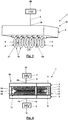
- the plasma treatment device 1 shown comprises an electrode arrangement 18 with two arc-shaped electrode bodies 2, each of which begins and ends in a base 3 made of electrically insulating material and initially in two planes running parallel to one another in a straight line away from the base 3, then over a 180 ° arc and last straight back to the base 3 extend.
- the cross section of the two electrode bodies 2, each sheathed with a dielectric 4, is circular here.
- a radius of curvature 20 with which the electrode bodies 2 change their direction in their arcuate regions 10 is here about five times as large as their smallest surface radius of curvature 21 due to their circular cross section.
- the electrode bodies 2 have this minimum surface radius of curvature 21 over their entire extensions from and to the base 3.
- the electrode bodies 2 in a closed housing 5 of a hand-held device are connected together via a high-voltage connection 19 to an output 6 of an alternating high-voltage generator 7, which is supplied with energy from an accumulator 8.
- the alternating high voltage generator 7 generates an alternating high voltage present at the output 6 with respect to its electrical ground.
- the alternating high voltage applied to the electrode body 2 causes gas discharges across the surface of the body, which lead to a surface treatment of the body lead with a physical plasma that arises as a result of the gas discharges.
- the gas discharges are distributed over the entire length of the electrode bodies 2 outside of the base 3 because they have their smallest surface curvature radius 21 over their entire length, which determines the maximum electric field with respect to the body to be treated.
- the plasma treatment device 1 is a plurality, ie more than two electrode bodies 2 are arranged next to one another in planes running parallel to one another, each beginning and ending in the same base 3 and being connected to the same output 6 of the alternating high voltage generator 7 via the same high voltage connection 19.
- the treatment space 9 extends between the electrode bodies 2 and up to their arcuate areas 10.
- Two bodies 11 are illustrated, the surfaces 12 of which are treated with a physical plasma in their areas opposite the electrode bodies 2 as a result of gas discharges 13 forming there.
- FIG. 11 shows a modification of the plasma treatment device 1 according to FIG Fig. 2 .
- the electrode bodies 2 are each loop-shaped or loop-shaped, they consist entirely of their arcuate regions 10 and change their directions over 360 ° over these with a constant radius of curvature 20.
- the treatment space 9 extends in front of the electrode bodies 2 and between the electrode bodies 2.
- the plasma treatment device 1 shown has two groups 14 and 15 of electrode bodies 2, each of which is mounted at the end in a base 3.
- the electrode bodies 2 of the two groups 14 and 15 are opposite one another with their arcuate regions 10, the electrode bodies 2 of the two groups, as in FIG Fig. 4 shown, can also lie against one another or can even engage in one another.
- the treatment space of the plasma treatment device 1 between the electrode bodies 2 also accommodates larger bodies for surface treatment in that the electrode bodies 2, including their sheathing with the dielectric 4, are designed to be deformable against restoring forces. For example, a hand to be disinfected can be pushed through a side opening 17 into a partially open housing 16 in which the two groups 14 and 15 of the electrode bodies 2 are arranged.
- an alternating high voltage is applied via the high voltage connections 19, namely the same to all electrode bodies 2, so that a resulting gas discharge is not caused between the electrode bodies 2, but between the surface of the body to be treated and the opposite or adjacent electrode bodies 2.
- the representation in Fig. 4 is therefore not to be understood as meaning that two alternating high voltage generators 7 generate independent alternating high voltages with respect to earth at their outputs 6.
- the dense distribution of the electrode bodies 2 adjacent to the respective body and the smallest surface curvature radii of the electrode bodies 2, which remain constant over the longitudinal extensions of the linear electrode bodies 2, ensure a large-area distribution of the discharge paths that form between the respective body and the electrode bodies 2. A rapid, full-area surface treatment of the body 2 with the physical plasma generated by the gas discharge thus takes place.
Description
Die Erfindung bezieht sich auf eine Elektrodenanordnung für eine Oberflächenbehandlung eines Körpers mit einem physikalischen Plasma, die die Merkmale des Oberbegriffs des unabhängigen Patentanspruchs 1 aufweist, sowie auf eine Plasmabehandlungsvorrichtung mit einem Wechselhochspannungsgenerator und einer solchen Elektrodenanordnung.The invention relates to an electrode arrangement for surface treatment of a body with a physical plasma, which has the features of the preamble of
Die Behandlung einer Oberfläche mit einem physikalischen Plasma kann aus unterschiedlichen Gründen erfolgen. Die jeweilige Oberfläche kann zum Zwecke einer besseren Haftung einer anschließenden Beschichtung physikalisch aktiviert werden, oder Keime oder Schädlinge an der Oberfläche können abgetötet werden. Entsprechend kann der Körper, dessen Oberfläche behandelt wird, ganz unterschiedlicher Natur sein. Es kann sich insbesondere um einen leblosen oder einen lebenden Körper handeln.The treatment of a surface with a physical plasma can take place for various reasons. The respective surface can be physically activated for the purpose of better adhesion of a subsequent coating, or germs or pests on the surface can be killed. Accordingly, the body, the surface of which is being treated, can be of very different nature. In particular, it can be a lifeless or a living body.
Die vorliegende Erfindung bezieht sich nicht auf eine Plasmabehandlung mit jeglichem physikalischen Plasma, sondern auf eine Plasmabehandlung mit einem sogenannten kalten Plasma, dessen Gastemperatur unter 100 °C und vorzugsweise in der Nähe der Umgebungstemperatur bleibt, so dass die Effekte des Plasmas zumindest weit überwiegend nicht thermischer Natur sind. Um ein kaltes Plasma durch eine Gasentladung zu erzeugen, ist die Gasentladung dielektrisch zu behindern, um den durch die Gasentladung fließenden Strom zu begrenzen. Eine dielektrische Barriere zur dielektrischen Behinderung der Gasentladung kann entweder vor einer an die Entladungsstrecke angrenzenden Elektrode, an der eine die Gasentladung hervorrufende Wechselhochspannung anliegt, oder auch zwischen der Elektrode und einem die Wechselhochspannung erzeugenden Wechselhochspannungsgenerator angeordnet werden.The present invention does not relate to a plasma treatment with any physical plasma, but to a plasma treatment with a so-called cold plasma, the gas temperature of which remains below 100 ° C. and preferably in the vicinity of the ambient temperature, so that the effects of the plasma are at least far predominantly non-thermal Are nature. In order to generate a cold plasma by means of a gas discharge, the gas discharge must be hindered dielectrically in order to limit the current flowing through the gas discharge. A dielectric barrier for dielectrically hindering the gas discharge can either be arranged in front of an electrode adjoining the discharge path, to which an alternating high voltage causing the gas discharge is applied, or between the electrode and an alternating high voltage generator generating the alternating high voltage.
Eine Elektrodenanordnung mit den Merkmalen des Oberbegriffs des unabhängigen Patentanspruchs 1 und eine entsprechende Plasmabehandlungsvorrichtung sind aus der
Eine Elektrodenanordnung mit den Merkmalen des Obergriffs des Anspruchs 1 und eine entsprechende Plasmabehandlungsvorrichtung sind auch aus der
Für eine schnelle großflächige Oberflächenbehandlung eines Körpers sind die bekannten Elektrodenanordnungen und die bekannten Plasmabehandlungsvorrichtungen nicht geeignet. Aus der
Aus der
Aus der
Aus der
Aus der
Aus der
Aus der
Aus der
Der Erfindung liegt die Aufgabe zugrunde, eine Elektrodenanordnung und eine mit einer solchen Elektrodenanordnung ausgestattete Plasmabehandlungsvorrichtung aufzuzeigen, die bei geringem Herstellungsaufwand eine schnelle großflächige Oberflächenbehandlung ermöglichen.The invention is based on the object of providing an electrode arrangement and a plasma treatment device equipped with such an electrode arrangement, which enable rapid, large-area surface treatment with little manufacturing effort.
Die Aufgabe der Erfindung wird durch eine Elektrodenanordnung mit den Merkmalen des unabhängigen Patentanspruchs 1 und eine Plasmabehandlungsvorrichtung mit den Merkmalen des nebengeordneten Patentanspruchs 14 gelöst. Bevorzugte Ausführungsformen der Elektrodenanordnung und der Plasmabehandlungsvorrichtung sind in den abhängigen Patentansprüchen definiert.The object of the invention is achieved by an electrode arrangement with the features of
Die Erfindung betrifft eine Elektrodenanordnung für eine Oberflächenbehandlung eines Körpers mit einem physikalischen Plasma, die einen Hochspannungsanschluss zum Anschließen an einen Ausgang einer eine Wechselhochspannung erzeugenden Wechselhochspannungsquelle und mehrere an den Hochspannungsanschluss angeschlossene linienförmige Elektrodenkörper aufweist. Die Elektrodenkörper sind derart gemeinsam an den Hochspannungsanschluss angeschlossen, dass an allen Elektrodenkörpern dieselbe Wechselhochspannung anliegt, und sie sind mit einem Dielektrikum ummantelt und/oder einzeln kapazitiv an den Hochspannungsanschluss gekoppelt. Die Elektrodenkörper sind insofern linienförmig als dass sie sich jeweils im Wesentlichen längs einer Linie erstrecken, bei der es sich aber um keine Gerade handelt. Erfindungsgemäß umfassen die Elektrodenkörper vielmehr jeweils einen bogenförmigen Bereich, in dem der jeweilige linienförmige Elektrodenkörper seine Richtung um mindestens 90° ändert. Ein an die Elektrodenkörper angrenzender Behandlungsraum, in den ein Körper für eine Oberflächenbehandlung mit dem physikalischen Plasma einzubringen ist, befindet sich zumindest teilweise zwischen diesen bogenförmigen Bereichen der Elektrodenkörper. Wenn an dem Hochspannungsanschluss und damit an den Elektrodenkörpern eine Wechselhochspannung gegenüber Erde oder Masse anliegt und wenn der für die Oberflächenbehandlung vorgesehene Körper geerdet ist oder eine ausreichend große elektrische Kapazität aufweist, bilden sich zwischen den bogenförmigen Bereichen der Elektrodenkörper und dem zu behandelnden Körper Gasentladungen aus. Die Entladungsstrecken verteilen sich dabei längs der bogenförmigen Bereiche der linienförmigen Elektrodenkörper, weil die größten elektrischen Felder, die im Bereich der kleinsten Oberflächenkrümmungsradien der Elektrodenkörper auftreten, über die bogenförmigen Bereiche verteilt und nicht etwa an einer zu dem jeweiligen zu behandelnden Körper weisenden freien Spitze der Elektrodenkörper konzentriert sind. Die dem zu behandelnden Körper zugekehrten kleinsten Oberflächenkrümmungsradien sind diejenigen der Oberfläche des Querschnitts der linienförmigen Elektrodenkörper, der über den bogenförmigen Bereich jedes Elektrodenkörpers vorzugsweise konstant ist. Durch die Verteilung der Entladungsstrecken längs der bogenförmigen Elektrodenkörper liegt ein mit der erfindungsgemäßen Elektrodenanordnung durch dielektrisch behinderte Gasentladung erzeugtes physikalisches Plasma großflächig über der Oberfläche des zu behandelnden Körpers vor. So wird diese Oberfläche schnell vollständig behandelt.The invention relates to an electrode arrangement for surface treatment of a body with a physical plasma, which has a high voltage connection for connection to an output of an alternating high voltage source generating an alternating high voltage and a plurality of linear electrode bodies connected to the high voltage connection. The electrode bodies are jointly connected to the high-voltage connection in such a way that the same alternating high voltage is applied to all electrode bodies, and they are sheathed with a dielectric and / or individually capacitively coupled to the high-voltage connection. The electrode bodies are linear to the extent that they each extend essentially along a line which, however, is not a straight line. According to the invention, the electrode bodies rather each comprise an arcuate region in which the respective linear electrode body changes its direction by at least 90 °. A treatment space adjoining the electrode bodies, into which a body is to be introduced for a surface treatment with the physical plasma, is located at least partially between these arcuate areas of the electrode bodies. If an alternating high voltage with respect to earth or ground is applied to the high-voltage connection and thus to the electrode bodies and if the body intended for the surface treatment is earthed or has a sufficiently large electrical capacity, gas discharges form between the arcuate areas of the electrode body and the body to be treated. The discharge paths are distributed along the arcuate areas of the linear electrode bodies because the largest electrical fields that occur in the area of the smallest surface curvature radii of the electrode bodies are distributed over the arcuate areas and not, for example, at a free tip of the electrode body pointing towards the body to be treated are focused. The smallest surface radii of curvature facing the body to be treated are those of the surface of the cross section of the linear electrode body, which is preferably constant over the arcuate area of each electrode body. Due to the distribution of the discharge paths along the arcuate electrode bodies, a physical plasma generated with the electrode arrangement according to the invention by dielectrically impeded gas discharge is present over a large area over the surface of the body to be treated. This way, this surface is completely treated quickly.
Die Elektrodenkörper können in ihren bogenförmigen Bereichen insbesondere eine äußere Oberfläche mit einem abgerundeten oder kreisrunden Querschnitt aufweisen, dessen Oberflächenkrümmungsradius über den Umfang des jeweiligen Elektrodenkörpers zumindest im Wesentlichen gleich ist. Grundsätzlich können die Elektrodenkörper aber auch eine äußere Oberfläche beispielsweise mit einem sternförmigen Querschnitt aufweisen, um an den Spitzen von Zacken des Sterns gezielt Feldspitzen des elektrischen Felds gegenüber einem zu behandelnden Körper hervorzurufen, die aber dennoch längs der linienförmigen Elektrodenkörper verteilt sind.In their arcuate regions, the electrode bodies can in particular have an outer surface with a rounded or circular cross section, the surface radius of curvature of which is at least substantially the same over the circumference of the respective electrode body. In principle, however, the electrode bodies can also have an outer surface, for example with a star-shaped cross-section, in order to specifically induce field peaks of the electrical field with respect to a body to be treated at the tips of the spikes of the star, which are nevertheless distributed along the linear electrode bodies.
Eine Krümmung, mit der der jeweilige linienförmige Elektrodenkörper in dem bogenförmigen Bereich seine Richtung ändert, kann grundsätzlich konstant sein, sie kann aber auch variieren. Typischerweise liegt der Krümmungsradius dieser Krümmung zwischen 3 mm und 300 mm. Oftmals liegt er zwischen 5 mm und 200 mm. Dieser Krümmungsradius ist in jedem Fall deutlich größer als der vorzugsweise über den bogenförmigen Bereich des jeweiligen linienförmigen Elektrodenkörpers gleichbleibende kleinste Oberflächenflächenkrümmungsradius. Dieser kleinste Oberflächenkrümmungsradius liegt typischerweise in einem Bereich zwischen 0,3 mm und 30 mm. In der Regel beträgt er zwischen 0,5 mm und 5 mm. Der Unterschied zwischen dem Krümmungsradius des bogenförmigen Bereichs und dem kleinsten Oberflächenkrümmungsradius des linienförmigen Elektrodenkörpers beträgt mindestens einen Faktor 3, häufig einen Faktor 5 oder 10 oder noch mehr.A curvature with which the respective linear electrode body changes its direction in the arcuate area can in principle be constant, but it can also vary. The radius of curvature of this curvature is typically between 3 mm and 300 mm. Often it is between 5 mm and 200 mm. This radius of curvature is in any case significantly larger than the smallest radius of curvature of the surface area, which preferably remains constant over the arcuate region of the respective linear electrode body. This smallest surface radius of curvature is typically in a range between 0.3 mm and 30 mm. Usually it is between 0.5 mm and 5 mm. The difference between the radius of curvature of the arcuate region and the smallest radius of curvature of the surface of the linear electrode body is at least a factor of 3, often a factor of 5 or 10 or even more.
Der jeweilige linienförmige Elektrodenkörper kann in dem bogenförmigen Bereich seine Richtung um deutlich mehr als 90° ändern, insbesondere um etwa 180°, d. h. mindestens 150° oder noch mehr. Der Elektrodenkörper wird damit zunehmend schleifen- oder schlaufenförmig. Insbesondere kann er sich dabei von und bis zu einem Sockel aus einem elektrisch isolierenden Material erstrecken. Das heißt, die Elektrodenkörper weisen keine freien Enden auf, sondern enden beidseitig in dem jeweiligen Sockel aus dem elektrisch isolierenden Material, in dem sie auch an Hochspannungsanschluss angeschlossen sein können. Jede Feldkonzentration an freien distalen Enden der Elektrodenkörper und eine damit verbundene nur punktuelle Ausbildung einer Gasentladung ausgehend von den distalen Enden der Elektrodenkörper wird damit vermieden.The respective linear electrode body can change its direction in the arcuate region by significantly more than 90 °, in particular by about 180 °, i.e. by about 180 °. H. at least 150 ° or more. The electrode body is thus increasingly loop-shaped or loop-shaped. In particular, it can extend from and to a base made of an electrically insulating material. This means that the electrode bodies do not have any free ends, but rather end on both sides in the respective base made of the electrically insulating material, in which they can also be connected to a high-voltage connection. Any field concentration at free distal ends of the electrode bodies and an associated only punctiform formation of a gas discharge starting from the distal ends of the electrode bodies is thus avoided.
Der Behandlungsraum, in dem eine Oberflächenbehandlung mit der erfindungsgemäßen Elektrodenanordnung erfolgt, kann sich zumindest teilweise zwischen zwei Ebenen befinden, in denen sich zwei einander benachbarte Elektrodenkörper mit ihren bogenförmigen Bereichen erstrecken. Dieser Behandlungsraum kann z. B. gegenüber einem blattförmigen Körper mit der Elektrodenanordnung verschoben werden, um die beiden einander gegenüberliegenden Oberflächen des blattförmigen Körpers mit dem physikalischen Plasma zu behandeln. So können beispielsweise von Parasiten oder Mikroorganismen befallene Blätter einer Pflanze mit dem physikalischen Plasma behandelt werden, um diese Parasiten bzw. Mikroorganismen abzutöten.The treatment room, in which a surface treatment with the electrode arrangement according to the invention takes place, can be at least partially located between two planes in which two adjacent electrode bodies extend with their arcuate areas. This treatment room can, for. B. relative to a sheet-shaped body with the electrode assembly to treat the two opposite surfaces of the sheet-shaped body with the physical plasma. For example, leaves of a plant infected by parasites or microorganisms can be treated with the physical plasma in order to kill these parasites or microorganisms.
Der Behandlungsraum kann sich zumindest teilweise auch zwischen zwei Gruppen der Elektrodenkörper erstrecken, deren bogenförmige Bereiche sich mit einander entgegen gerichteten Krümmungsradien gegenüberliegen. Auch in diesem Fall ist es bei der erfindungsgemäßen Elektrodenanordnung so, dass alle Elektrodenkörper, d. h. die Elektrodenkörper beider Gruppen, an einen gemeinsamen Hochspannungsanschluss angeschlossen sind und dass die Gasentladungen dementsprechend nicht zwischen den beiden Gruppen von Elektrodenkörpern, sondern gegenüber einem in dem Behandlungsraum eingebrachten Körper hervorgerufen werden.The treatment space can also extend at least partially between two groups of electrode bodies, the arcuate areas of which are opposite one another with radii of curvature directed opposite one another. In this case, too, with the electrode arrangement according to the invention, all electrode bodies, ie. H. the electrode bodies of both groups are connected to a common high-voltage connection and that the gas discharges are accordingly not caused between the two groups of electrode bodies, but rather in relation to a body introduced into the treatment room.
Die bogenförmigen Bereiche der Elektrodenkörper jeder Gruppe können in zueinander parallelen Ebenen verlaufen. Hiermit wird eine gleichmäßige und dichte Verteilung der Elektrodenkörper und der damit hervorgerufenen Gasentladungen bewirkt. Die Elektrodenkörper können sich dabei sowohl innerhalb einer Gruppe oder auch über die beiden Gruppen hinweg berühren, ohne dass dies der Funktion der Elektrodenanordnung einen Abbruch tut, weil an allen Elektrodenkörpern dieselbe Wechselhochspannung anliegt.The arcuate areas of the electrode bodies of each group can run in planes parallel to one another. This brings about a uniform and dense distribution of the electrode bodies and the gas discharges caused thereby. The electrode bodies can touch either within a group or across the two groups, without this affecting the function of the electrode arrangement, because the same alternating high voltage is applied to all electrode bodies.
Zumindest in ihren bogenförmigen Bereichen, d. h. auch insgesamt, können die Elektrodenkörper gegen Rückstellkräfte verformbar sein. So kann ein zu behandelnder Körper, wenn er in den Behandlungsraum eingebracht wird, die den Behandlungsraum begrenzenden Elektrodenkörper so weit auseinanderschieben, dass er in den Behandlungsraum passt. Die Elektrodenkörper befinden sich damit in der unmittelbaren Nähe der Oberfläche des zu behandelnden Körpers.At least in their arcuate areas, i. H. also overall, the electrode bodies can be deformable against restoring forces. Thus, when a body to be treated is introduced into the treatment room, the electrode bodies delimiting the treatment room can be pushed apart so far that it fits into the treatment room. The electrode bodies are therefore in the immediate vicinity of the surface of the body to be treated.
Die Verformbarkeit der Elektrodenkörper kann gegen elastische Kräfte und/oder Gravitationskräfte gegeben sein, so dass sich die Elektrodenkörper selbsttätig zurückverformen, wenn beispielsweise der behandelte Körper wieder aus dem Behandlungsraum entfernt wird.The deformability of the electrode bodies can be given against elastic forces and / or gravitational forces, so that the electrode bodies automatically deform back when, for example, the treated body is removed from the treatment room.
Die Elektrodenkörper können in einem den Behandlungsraum teilweise umschließenden Gehäuse angeordnet sein. Durch eine verbleibende Öffnung des Gehäuses kann der jeweils zu behandelnde Körper in den Behandlungsraum eingebracht werden. Das Gehäuse, in dem die Elektrodenkörper angeordnet sind, kann aus Sicherheitsgründen geerdet sein.The electrode bodies can be arranged in a housing partially enclosing the treatment room. The body to be treated can be brought into the treatment room through a remaining opening in the housing. The housing in which the electrode bodies are arranged can be earthed for safety reasons.
Eine erfindungsgemäße Plasmabehandlungsvorrichtung mit einem Wechselhochspannungsgenerator, der an einem Ausgang eine Wechselhochspannung gegenüber Erde erzeugt, weist eine an den Ausgang des Wechselhochspannungsgenerators angeschlossene erfindungsgemäße Elektrodenanordnung auf.A plasma treatment device according to the invention with an alternating high voltage generator which generates an alternating high voltage with respect to earth at an output, has an electrode arrangement according to the invention connected to the output of the alternating high voltage generator.
Der Wechselhochspannungsgenerator kann Wechselhochspannungen zwischen etwa 5 kV und 50 kV, insbesondere zwischen 5 kV und 30 kV erzeugen.The alternating high voltage generator can generate alternating high voltages between approximately 5 kV and 50 kV, in particular between 5 kV and 30 kV.
In diesen und anderen Ausführungsformen der erfindungsgemäßen Vorrichtung kann der Wechselhochspannungsgenerator die Wechselhochspannung mit einer Frequenz zwischen etwa 100 kHz und etwa 3 MHz oder zwischen 150 kHz und etwa 1 MHz oder zwischen 200 kHz und 600 kHz erzeugen. Durch diese Frequenzen der Wechselhochspannung wird eine erhöhte Betriebssicherheit der erfindungsgemäßen Vorrichtung gewährleistet, da auf Grund des Skineffektes bei einer versehentlichen Berührung von Teilen der Vorrichtung, an denen diese Wechselhochspannung anliegt, der resultierende elektrische Strom lediglich die Oberfläche des Körpers der berührenden Person entlang fließt und nicht tief in darunter liegendes Gewebe eindringt. Eine Gefährdung des Benutzers der erfindungsgemäßen Vorrichtung kann so ausgeschlossen werden.In these and other embodiments of the device according to the invention, the alternating high voltage generator can generate the alternating high voltage with a frequency between approximately 100 kHz and approximately 3 MHz or between 150 kHz and approximately 1 MHz or between 200 kHz and 600 kHz. These frequencies of the alternating high voltage ensure increased operational reliability of the device according to the invention, because due to the skin effect, if parts of the device to which this alternating high voltage is applied accidentally touch the resulting electric current only the surface of the device Body of the person being touched and does not penetrate deeply into the underlying tissue. Endangering the user of the device according to the invention can thus be excluded.
Zusätzlich kann die Wechselhochspannung getaktet werden, um den thermischen Eintrag in das zu behandelnde Objekt und auch in den Körper einer mit der Wechselhochspannung in Berührung kommenden Person zu begrenzen. Dabei ist unter einer Taktung der Wechselhochspannung eine Unterbrechung der Wechselhochspannung nach jeweils einer Gruppe von Hochspannungspulsen wechselnder Polarität zu verstehen. Eine solche Gruppe kann z. B. einige bis einige zehn Hochspannungspulse wechselnder Polarität umfassen. Durch die Taktung der Wechselhochspannung kann trotz der Frequenz der Wechselhochspannung größer 100 kHz eine mittlere Pulswiederholungsfrequenz der Hochspannungspulse insbesondere in dem Bereich von 3 kHz bis 50 kHz eingestellt werden.In addition, the alternating high voltage can be clocked in order to limit the thermal input into the object to be treated and also into the body of a person coming into contact with the alternating high voltage. A pulsing of the alternating high voltage is to be understood as an interruption of the alternating high voltage after each group of high voltage pulses of alternating polarity. Such a group can e.g. B. comprise a few to a few tens of high voltage pulses of alternating polarity. Due to the pulsing of the alternating high voltage, despite the frequency of the alternating high voltage greater than 100 kHz, an average pulse repetition frequency of the high voltage pulses can be set, in particular in the range from 3 kHz to 50 kHz.
Bei Taktung der Wechselhochspannung kann durch Variation der Anzahl der Hochspannungspulse in jeder Gruppe und/oder einer Gruppenfolgefrequenz, mit der die einzelnen Gruppen der Hochspannungspulse aufeinander folgen, eine elektrische Leistung der durch die Wechselhochspannung hervorgerufenen Gasentladung auf einen gewünschten Wert, insbesondere einen gewünschten Wert pro Flächeneinheit der Oberfläche des behandelten Objekts, eingestellt werden. Diese Flächenleistungsdichte kann zwischen 0,1 bis 10 W/cm2 liegen.When the alternating high voltage is pulsed, by varying the number of high voltage pulses in each group and / or a group repetition frequency with which the individual groups of high voltage pulses follow one another, an electrical power of the gas discharge caused by the alternating high voltage can be reduced to a desired value, in particular a desired value per unit area the surface of the treated object. This surface power density can be between 0.1 and 10 W / cm 2 .
Die Gesamtausgangsleistung des Wechselhochspannungsgenerator kann in einem typischen Bereich von 5 W bis 500 W liegen.The total output power of the alternating high voltage generator can be in a typical range from 5 W to 500 W.
Die Gruppenfolgefrequenz der Gruppen der Hochspannungspulse kann in einem Bereich jenseits der vom Menschen hörbaren Frequenzen liegen, d. h. mindestens 16 kHz betragen, so dass der Betrieb der Vorrichtung keine Geräusche mit der Wiederholungsfrequenz verursacht. Die Gruppenfolgefrequenz kann auch deutlich höher als die Grenze des hörbaren Bereichs liegen, d. h. mindestens 20 kHz oder mindestens 30 kHz betragen, so dass mit ihr keinerlei vom Menschen wahrnehmbare Schwingungsanregungen verbunden sind.The group repetition frequency of the groups of high-voltage pulses can be in a range beyond the frequencies that can be heard by humans, i. H. be at least 16 kHz so that the operation of the device does not cause noise at the repetition frequency. The group repetition rate can also be significantly higher than the limit of the audible range; H. be at least 20 kHz or at least 30 kHz, so that it is not associated with any vibration excitations that can be perceived by humans.
Vorteilhafte Weiterbildungen der Erfindung ergeben sich aus den Patentansprüchen, der Beschreibung und den Zeichnungen. Die in der Beschreibung genannten Vorteile von Merkmalen und von Kombinationen mehrerer Merkmale sind lediglich beispielhaft und können alternativ oder kumulativ zur Wirkung kommen, ohne dass die Vorteile zwingend von erfindungsgemäßen Ausführungsformen erzielt werden müssen. Ohne dass hierdurch der Gegenstand der beigefügten Patentansprüche verändert wird, gilt hinsichtlich des Offenbarungsgehalts der ursprünglichen Anmeldungsunterlagen und des Patents Folgendes: weitere Merkmale sind den Zeichnungen - insbesondere den dargestellten Geometrien und den relativen Abmessungen mehrerer Bauteile zueinander sowie deren relativer Anordnung und Wirkverbindung - zu entnehmen. Die Kombination von Merkmalen unterschiedlicher Ausführungsformen der Erfindung oder von Merkmalen unterschiedlicher Patentansprüche ist ebenfalls abweichend von den gewählten Rückbeziehungen der Patentansprüche möglich und wird hiermit angeregt. Dies betrifft auch solche Merkmale, die in separaten Zeichnungen dargestellt sind oder bei deren Beschreibung genannt werden. Diese Merkmale können auch mit Merkmalen unterschiedlicher Patentansprüche kombiniert werden. Ebenso können in den Patentansprüchen aufgeführte Merkmale für weitere Ausführungsformen der Erfindung entfallen.Advantageous further developments of the invention emerge from the patent claims, the description and the drawings. The advantages of features and of combinations of several features mentioned in the description are merely exemplary and can be alternative or come into effect cumulatively without the advantages necessarily having to be achieved by embodiments according to the invention. Without changing the subject matter of the attached claims, the following applies to the disclosure content of the original application documents and the patent: Further features can be found in the drawings - in particular the illustrated geometries and the relative dimensions of several components to one another and their relative arrangement and operative connection. The combination of features of different embodiments of the invention or of features of different patent claims is also possible, deviating from the selected back-references of the patent claims, and is hereby suggested. This also applies to features that are shown in separate drawings or mentioned in their description. These features can also be combined with features of different patent claims. Features listed in the claims for further embodiments of the invention can also be omitted.
Die in den Patentansprüchen und der Beschreibung genannten Merkmale sind bezüglich ihrer Anzahl so zu verstehen, dass genau diese Anzahl oder eine größere Anzahl als die genannte Anzahl vorhanden ist, ohne dass es einer expliziten Verwendung des Adverbs "mindestens" bedarf. Wenn also beispielsweise von einem Element die Rede ist, ist dies so zu verstehen, dass genau ein Element, zwei Elemente oder mehr Elemente vorhanden sind. Die in den Patentansprüchen angeführten Elemente können durch andere Elemente ergänzt werden oder die einzigen Elemente sein, aus denen das jeweilige Erzeugnis besteht.The number of features mentioned in the claims and the description are to be understood in such a way that precisely this number or a greater number than the stated number is present without the need for the explicit use of the adverb "at least". For example, if an element is mentioned, it is to be understood that there is exactly one element, two elements or more elements. The elements listed in the patent claims can be supplemented by other elements or be the only elements that make up the respective product.
Die in den Patentansprüchen enthaltenen Bezugszeichen stellen keine Beschränkung des Umfangs der durch die Patentansprüche geschützten Gegenstände dar. Sie dienen lediglich dem Zweck, die Patentansprüche leichter verständlich zu machen.The reference signs contained in the claims do not represent a restriction of the scope of the subject matter protected by the claims. They only serve the purpose of making the claims easier to understand.
Im Folgenden wird die Erfindung anhand in den Figuren dargestellter bevorzugter Ausführungsbeispiele weiter erläutert und beschrieben.
- Fig. 1
- zeigt eine als Handgerät ausgebildete erfindungsgemäße Plasmabehandlungsvorrichtung mit zwei Elektrodenkörpern.
- Fig. 2
- zeigt eine Ausführungsform einer erfindungsgemäßen Plasmabehandlungsvorrichtung mit einer Vielzahl von nebeneinander angeordneten bogenförmigen Elektrodenkörpern.
- Fig. 3
- zeigt eine Ausführungsform der erfindungsgemäßen Plasmabehandlungsvorrichtung mit einer Vielzahl von nebeneinander angeordneten schlaufenförmigen Elektrodenkörpern; und
- Fig. 4
- zeigt eine Ausführungsform der erfindungsgemäßen Plasmabehandlungsvorrichtung mit zwei einander gegenüberliegenden Gruppen von bogenförmigen Elektrodenkörpern.
- Fig. 1
- shows a plasma treatment device according to the invention, designed as a hand-held device, with two electrode bodies.
- Fig. 2
- shows an embodiment of a plasma treatment device according to the invention with a plurality of arc-shaped electrode bodies arranged next to one another.
- Fig. 3
- shows an embodiment of the plasma treatment device according to the invention with a plurality of loop-shaped electrode bodies arranged next to one another; and
- Fig. 4
- shows an embodiment of the plasma treatment device according to the invention with two opposing groups of arcuate electrode bodies.
Die in
Bei der Ausführungsform der Plasmabehandlungsvorrichtung 1 gemäß
Die in
- 11
- PlasmabehandlungsvorrichtungPlasma treatment device
- 22
- ElektrodenkörperElectrode body
- 33
- Sockelbase
- 44th
- Dielektrikumdielectric
- 55
- Gehäusecasing
- 66th
- Ausgangoutput
- 77th
- WechselhochspannungsgeneratorAC high voltage generator
- 88th
- Akkumulatoraccumulator
- 99
- BehandlungsraumTreatment room
- 1010
- bogenförmiger Bereicharcuate area
- 1111
- Körperbody
- 1212
- Oberflächesurface
- 1313
- GasentladungGas discharge
- 1414th
- Gruppegroup
- 1515th
- Gruppegroup
- 1616
- Gehäusecasing
- 1717th
- Öffnungopening
- 1818th
- ElektrodenanordnungElectrode arrangement
- 1919th
- HochspannungsanschlussHigh voltage connection
- 2020th
- KrümmungsradiusRadius of curvature
- 2121st
- OberflächenkrümmungsradiusSurface radius of curvature
Claims (15)
- Electrode arrangement (18) for a surface treatment of a body (11) with a physical plasma, comprising:- a high voltage connection (19) for connecting to an output (6) of an alternating high voltage source generating an alternating high voltage;- several line-shaped electrode bodies (2) which are together connected to the alternating high voltage connection (19) in such a way that the same alternating high voltage is present at all electrode bodies (2), and which are covered by a dielectric (4) and/or individually capacitively coupled to the high voltage connection (19); and- a treatment space (9) adjoining the electrode bodies (2), in which the body (11) can be introduced for the surface treatment with the physical plasma;
characterised in that each of the electrode bodies (2) includes an arch-shaped area (20) in which the respective line-shaped electrode body (2) changes its direction by at least 90°, wherein the treatment space (9) is at least partially located between the arch-shaped areas (10) of the electrode bodies (2). - Electrode arrangement (18) of claim 1, characterised in that a radius of curvature (10) at which the respective line-shaped electrode body (2) changes its direction in the arch-shaped area (10) is between 3 mm and 300 mm or between 5 mm and 200 mm.
- Electrode arrangement (18) of claim 1 or 2, characterised in that the respective line-shaped electrode body (2) has a constant smallest radius of surface curvature (21) between 0.3 mm and 30 mm or between 0.5 mm and 5 mm in the arch-shaped area (10).
- Electrode arrangement (18) of any of the preceding claims, characterised in that the electrode bodies (2) have an outer surface with a rounded or circular cross section in the arch-shaped area (10).
- Electrode arrangement (18) of any of the preceding claims, characterised in that the respective line-shaped electrode body (2) changes its direction by at least 150° in the arch-shaped area (10).
- Electrode arrangement (18) of any of the preceding claims, characterised in that the respective line-shaped electrode body (2) extends from and up to a socket (3) made of an electrically isolating material.
- Electrode arrangement (18) of any of the preceding claims, characterised in that the treatment space (9) is at least partially located between two planes in which two neighbouring electrode bodies (2) extend with their arch-shaped areas (10).
- Electrode arrangement (18) of any of the preceding claims, characterised in that the treatment space (9) at least partially extends between two groups (14, 15) of the electrode bodies (2), whose arch-shaped areas (10) are opposite to each other with opposing radiuses of curvature.
- Electrode arrangement (18) of claim 8, characterised in that the arch-shaped areas (10) of the electrode bodies (2) of each group (14, 15) run in planes which are parallel to each other.
- Electrode arrangement (18) of any of the preceding claims, characterised in that the electrode bodies (2) are deformable in the arch-shaped areas (10).
- Electrode arrangement (18) of any of the preceding claims, characterised in that the electrode bodies (2) are deformable against elastic forces and/or gravitational forces.
- Electrode arrangement (18) of any of the preceding claims, characterised in that the electrode bodies (2) are arranged in a housing (16) partially enclosing the treatment space (9).
- Electrode arrangement (18) of claim 12, characterised in that the housing (16) is grounded.
- Plasma treatment apparatus (1) comprising an alternative high voltage generator (7) generating an alternative high voltage with regard to ground or earth at an output (6), and an electrode arrangement (18) of any of the preceding claims which is connected to the output (16) of the alternating high voltage generator (7).
- Plasma treatment apparatus (1) of claim 14, characterised in that the alternating high voltage generator (7) generates an alternative high voltage of 5 kV to 30 kV in form of high voltage pulse pairs having a pulse repetition frequency of 3 kHz to 50 kHz and an electric power of 5 W to 500 W.
Applications Claiming Priority (2)
| Application Number | Priority Date | Filing Date | Title |
|---|---|---|---|
| DE102015112200.6A DE102015112200A1 (en) | 2015-07-27 | 2015-07-27 | Electrode assembly and plasma treatment device for a surface treatment of a body |
| PCT/EP2016/064440 WO2017016761A1 (en) | 2015-07-27 | 2016-06-22 | Electrode arrangement and plasma-treatment apparatus for surface-treating a body |
Publications (2)
| Publication Number | Publication Date |
|---|---|
| EP3329747A1 EP3329747A1 (en) | 2018-06-06 |
| EP3329747B1 true EP3329747B1 (en) | 2020-09-23 |
Family
ID=56235806
Family Applications (1)
| Application Number | Title | Priority Date | Filing Date |
|---|---|---|---|
| EP16732268.4A Active EP3329747B1 (en) | 2015-07-27 | 2016-06-22 | Electrode arrangement and plasma-treatment apparatus for surface-treating a body |
Country Status (4)
| Country | Link |
|---|---|
| EP (1) | EP3329747B1 (en) |
| CN (1) | CN107926106B (en) |
| DE (1) | DE102015112200A1 (en) |
| WO (1) | WO2017016761A1 (en) |
Families Citing this family (5)
| Publication number | Priority date | Publication date | Assignee | Title |
|---|---|---|---|---|
| DE102018126492A1 (en) * | 2018-10-24 | 2020-04-30 | Cinogy Gmbh | Plasma treatment device |
| DE102018126489A1 (en) * | 2018-10-24 | 2020-04-30 | Cinogy Gmbh | Plasma treatment device with brush head |
| DE102019101063B4 (en) * | 2019-01-16 | 2021-02-25 | Cinogy Gmbh | Plasma treatment arrangement and method for adapting the size of a support surface of the plasma treatment arrangement to the size of the surface to be treated |
| DE102019107321A1 (en) * | 2019-03-21 | 2020-09-24 | Relyon Plasma Gmbh | Device for generating a plasma and method for plasma treatment of a surface |
| DE102019128538B3 (en) * | 2019-10-22 | 2021-02-04 | Hochschule für Angewandte Wissenschaft und Kunst - Hildesheim/Holzminden/Göttingen | Apparatus for forming physical plasma on a surface of an object |
Family Cites Families (19)
| Publication number | Priority date | Publication date | Assignee | Title |
|---|---|---|---|---|
| JPH0734389B2 (en) * | 1990-10-17 | 1995-04-12 | 住友精密工業株式会社 | Coated fine wire type active species generator |
| US6494881B1 (en) * | 1997-09-30 | 2002-12-17 | Scimed Life Systems, Inc. | Apparatus and method for electrode-surgical tissue removal having a selectively insulated electrode |
| US6887440B2 (en) * | 2000-11-16 | 2005-05-03 | Delphi Technologies, Inc. | Edge-connected non-thermal plasma exhaust after-treatment device |
| US6800256B2 (en) * | 2000-12-18 | 2004-10-05 | Delphi Technologies, Inc. | Scaleable inter-digitized tine non-thermal plasma reactor |
| US20050067934A1 (en) * | 2003-09-26 | 2005-03-31 | Ishikawajima-Harima Heavy Industries Co., Ltd. | Discharge apparatus, plasma processing method and solar cell |
| DE102007030915A1 (en) | 2007-07-03 | 2009-01-22 | Cinogy Gmbh | Device for the treatment of surfaces with a plasma generated by means of an electrode via a solid dielectric by a dielectrically impeded gas discharge |
| US20100275950A1 (en) * | 2007-12-10 | 2010-11-04 | Helmut Mack | Method and device for the treatment of surfaces |
| GB0906091D0 (en) * | 2009-04-07 | 2009-05-20 | Snowball Malcolm R | None invasive disinfector |
| DE102009028190A1 (en) * | 2009-08-03 | 2011-02-10 | Leibniz-Institut für Plasmaforschung und Technologie e.V. | Cold plasma beam producing device i.e. plasma hand-held device, for microplasma treatment of materials for e.g. cosmetic purpose, has high frequency-generator, coil, body and high voltage-electrode integrally arranged in metal housing |
| DE102009045498B4 (en) * | 2009-10-08 | 2015-12-24 | Hochschule für angewandte Wissenschaft und Kunst Fachhochschule Hildesheim/Holzminden/Göttingen | Method and apparatus for killing parasites and their preforms on filamentous material |
| DE102009060627B4 (en) | 2009-12-24 | 2014-06-05 | Cinogy Gmbh | Electrode arrangement for a dielectrically impeded plasma treatment |
| US8979838B2 (en) * | 2010-05-24 | 2015-03-17 | Arthrocare Corporation | Symmetric switching electrode method and related system |
| GB201107692D0 (en) * | 2011-05-09 | 2011-06-22 | Snowball Malcolm R | Sterilisation of packed articles |
| DE102011050631A1 (en) | 2011-05-25 | 2012-11-29 | Hochschule für Angewandte Wissenschaft und Kunst - Hildesheim/Holzminden/Göttingen | Devices for generating electrical discharges of low energy, in particular for combating hairless lice |
| DE102011105713B4 (en) * | 2011-06-23 | 2014-06-05 | Cinogy Gmbh | Electrode arrangement for a dielectrically impeded gas discharge |
| DE102012103362A1 (en) * | 2012-04-18 | 2013-10-24 | Chen Xiaobo | Pin-shaped plasma treatment apparatus for e.g. sterilization of skin or mucous membrane portion of human body, has electrode provided in pin part grounded in region of electrode, and another electrode provided on surface |
| CN103889138B (en) * | 2012-12-24 | 2016-06-29 | 中国科学院微电子研究所 | Plasma discharge apparatus |
| DE102013000440B4 (en) * | 2013-01-15 | 2014-07-24 | Cinogy Gmbh | Plasma treatment device with a rotatably mounted in a handle housing role |
| JP2015116811A (en) * | 2013-11-15 | 2015-06-25 | 株式会社リコー | Device for reforming object to be treated, printer, printing system, and method for manufacturing printed matter |
-
2015
- 2015-07-27 DE DE102015112200.6A patent/DE102015112200A1/en not_active Withdrawn
-
2016
- 2016-06-22 EP EP16732268.4A patent/EP3329747B1/en active Active
- 2016-06-22 CN CN201680044416.0A patent/CN107926106B/en active Active
- 2016-06-22 WO PCT/EP2016/064440 patent/WO2017016761A1/en active Application Filing
Non-Patent Citations (1)
| Title |
|---|
| None * |
Also Published As
| Publication number | Publication date |
|---|---|
| CN107926106B (en) | 2020-11-27 |
| DE102015112200A1 (en) | 2017-02-02 |
| WO2017016761A1 (en) | 2017-02-02 |
| EP3329747A1 (en) | 2018-06-06 |
| CN107926106A (en) | 2018-04-17 |
Similar Documents
| Publication | Publication Date | Title |
|---|---|---|
| EP3329747B1 (en) | Electrode arrangement and plasma-treatment apparatus for surface-treating a body | |
| EP2163143B1 (en) | Device for the treatment of surfaces with a plasma generated by an electrode over a solid dielectric via a dielectric barrier gas discharge | |
| EP3171676B1 (en) | Plasma generating device, plasma generating system and method of generating plasma | |
| DE102008045830A1 (en) | A method of treating a living cell containing biological material | |
| DE102015101391B4 (en) | Plasma generating device, plasma generating system, plasma generating method and surface disinfection method | |
| DE102009047220A1 (en) | Apparatus and method for generating a pulsed anisothermic atmospheric pressure plasma | |
| WO2011015538A1 (en) | Device for generating a non-thermal atmospheric pressure plasma | |
| EP2890318B1 (en) | Apparatus for treating biological tissue using a low-pressure plasma | |
| DE102009028190A1 (en) | Cold plasma beam producing device i.e. plasma hand-held device, for microplasma treatment of materials for e.g. cosmetic purpose, has high frequency-generator, coil, body and high voltage-electrode integrally arranged in metal housing | |
| EP3373787B1 (en) | Method and device for the drying and plasma-assisted disinfection of hands | |
| DE102009045498B4 (en) | Method and apparatus for killing parasites and their preforms on filamentous material | |
| DE102017118652A1 (en) | Plasma generator module and its use | |
| EP2713807B1 (en) | Device for producing electrical discharges of low energy, in particular in order to fight hair lice | |
| DE102014213967A1 (en) | Apparatus for the Hydophilization of Dental Implants | |
| DE202018106346U1 (en) | Plasma treatment device | |
| DE102016205821B4 (en) | Plasma source for wound treatment | |
| DE102019128538B3 (en) | Apparatus for forming physical plasma on a surface of an object | |
| DE102021128964B3 (en) | Process and device for generating plasmas with increased pulse energy by means of dielectrically impeded electrical discharges | |
| DE102007024027B4 (en) | Method and device for the combined treatment of a surface with a plasma and with electromagnetic radiation and their application | |
| EP3435746A1 (en) | Electrode for treating surfaces | |
| WO2017037223A1 (en) | Device for generating a plasma jet and method for surface treatment |
Legal Events
| Date | Code | Title | Description |
|---|---|---|---|
| STAA | Information on the status of an ep patent application or granted ep patent |
Free format text: STATUS: THE INTERNATIONAL PUBLICATION HAS BEEN MADE |
|
| PUAI | Public reference made under article 153(3) epc to a published international application that has entered the european phase |
Free format text: ORIGINAL CODE: 0009012 |
|
| STAA | Information on the status of an ep patent application or granted ep patent |
Free format text: STATUS: REQUEST FOR EXAMINATION WAS MADE |
|
| 17P | Request for examination filed |
Effective date: 20180131 |
|
| AK | Designated contracting states |
Kind code of ref document: A1 Designated state(s): AL AT BE BG CH CY CZ DE DK EE ES FI FR GB GR HR HU IE IS IT LI LT LU LV MC MK MT NL NO PL PT RO RS SE SI SK SM TR |
|
| AX | Request for extension of the european patent |
Extension state: BA ME |
|
| RIN1 | Information on inventor provided before grant (corrected) |
Inventor name: KOEHLER, ROBERT Inventor name: WIENEKE, STEPHAN Inventor name: VIOEL, WOLFGANG Inventor name: TEN BOSCH, LARS |
|
| DAV | Request for validation of the european patent (deleted) | ||
| DAX | Request for extension of the european patent (deleted) | ||
| RIN1 | Information on inventor provided before grant (corrected) |
Inventor name: VIOEL, WOLFGANG Inventor name: TEN BOSCH, LARS Inventor name: KOEHLER, ROBERT Inventor name: WIENEKE, STEPHAN |
|
| GRAP | Despatch of communication of intention to grant a patent |
Free format text: ORIGINAL CODE: EPIDOSNIGR1 |
|
| STAA | Information on the status of an ep patent application or granted ep patent |
Free format text: STATUS: GRANT OF PATENT IS INTENDED |
|
| INTG | Intention to grant announced |
Effective date: 20200513 |
|
| GRAS | Grant fee paid |
Free format text: ORIGINAL CODE: EPIDOSNIGR3 |
|
| GRAA | (expected) grant |
Free format text: ORIGINAL CODE: 0009210 |
|
| STAA | Information on the status of an ep patent application or granted ep patent |
Free format text: STATUS: THE PATENT HAS BEEN GRANTED |
|
| AK | Designated contracting states |
Kind code of ref document: B1 Designated state(s): AL AT BE BG CH CY CZ DE DK EE ES FI FR GB GR HR HU IE IS IT LI LT LU LV MC MK MT NL NO PL PT RO RS SE SI SK SM TR |
|
| REG | Reference to a national code |
Ref country code: GB Ref legal event code: FG4D Free format text: NOT ENGLISH |
|
| REG | Reference to a national code |
Ref country code: CH Ref legal event code: EP |
|
| REG | Reference to a national code |
Ref country code: DE Ref legal event code: R096 Ref document number: 502016011262 Country of ref document: DE |
|
| REG | Reference to a national code |
Ref country code: IE Ref legal event code: FG4D Free format text: LANGUAGE OF EP DOCUMENT: GERMAN |
|
| REG | Reference to a national code |
Ref country code: AT Ref legal event code: REF Ref document number: 1317759 Country of ref document: AT Kind code of ref document: T Effective date: 20201015 |
|
| PG25 | Lapsed in a contracting state [announced via postgrant information from national office to epo] |
Ref country code: FI Free format text: LAPSE BECAUSE OF FAILURE TO SUBMIT A TRANSLATION OF THE DESCRIPTION OR TO PAY THE FEE WITHIN THE PRESCRIBED TIME-LIMIT Effective date: 20200923 Ref country code: HR Free format text: LAPSE BECAUSE OF FAILURE TO SUBMIT A TRANSLATION OF THE DESCRIPTION OR TO PAY THE FEE WITHIN THE PRESCRIBED TIME-LIMIT Effective date: 20200923 Ref country code: SE Free format text: LAPSE BECAUSE OF FAILURE TO SUBMIT A TRANSLATION OF THE DESCRIPTION OR TO PAY THE FEE WITHIN THE PRESCRIBED TIME-LIMIT Effective date: 20200923 Ref country code: NO Free format text: LAPSE BECAUSE OF FAILURE TO SUBMIT A TRANSLATION OF THE DESCRIPTION OR TO PAY THE FEE WITHIN THE PRESCRIBED TIME-LIMIT Effective date: 20201223 Ref country code: GR Free format text: LAPSE BECAUSE OF FAILURE TO SUBMIT A TRANSLATION OF THE DESCRIPTION OR TO PAY THE FEE WITHIN THE PRESCRIBED TIME-LIMIT Effective date: 20201224 Ref country code: BG Free format text: LAPSE BECAUSE OF FAILURE TO SUBMIT A TRANSLATION OF THE DESCRIPTION OR TO PAY THE FEE WITHIN THE PRESCRIBED TIME-LIMIT Effective date: 20201223 |
|
| PG25 | Lapsed in a contracting state [announced via postgrant information from national office to epo] |
Ref country code: RS Free format text: LAPSE BECAUSE OF FAILURE TO SUBMIT A TRANSLATION OF THE DESCRIPTION OR TO PAY THE FEE WITHIN THE PRESCRIBED TIME-LIMIT Effective date: 20200923 Ref country code: LV Free format text: LAPSE BECAUSE OF FAILURE TO SUBMIT A TRANSLATION OF THE DESCRIPTION OR TO PAY THE FEE WITHIN THE PRESCRIBED TIME-LIMIT Effective date: 20200923 |
|
| REG | Reference to a national code |
Ref country code: NL Ref legal event code: MP Effective date: 20200923 |
|
| REG | Reference to a national code |
Ref country code: LT Ref legal event code: MG4D |
|
| PG25 | Lapsed in a contracting state [announced via postgrant information from national office to epo] |
Ref country code: EE Free format text: LAPSE BECAUSE OF FAILURE TO SUBMIT A TRANSLATION OF THE DESCRIPTION OR TO PAY THE FEE WITHIN THE PRESCRIBED TIME-LIMIT Effective date: 20200923 Ref country code: CZ Free format text: LAPSE BECAUSE OF FAILURE TO SUBMIT A TRANSLATION OF THE DESCRIPTION OR TO PAY THE FEE WITHIN THE PRESCRIBED TIME-LIMIT Effective date: 20200923 Ref country code: RO Free format text: LAPSE BECAUSE OF FAILURE TO SUBMIT A TRANSLATION OF THE DESCRIPTION OR TO PAY THE FEE WITHIN THE PRESCRIBED TIME-LIMIT Effective date: 20200923 Ref country code: SM Free format text: LAPSE BECAUSE OF FAILURE TO SUBMIT A TRANSLATION OF THE DESCRIPTION OR TO PAY THE FEE WITHIN THE PRESCRIBED TIME-LIMIT Effective date: 20200923 Ref country code: PT Free format text: LAPSE BECAUSE OF FAILURE TO SUBMIT A TRANSLATION OF THE DESCRIPTION OR TO PAY THE FEE WITHIN THE PRESCRIBED TIME-LIMIT Effective date: 20210125 Ref country code: LT Free format text: LAPSE BECAUSE OF FAILURE TO SUBMIT A TRANSLATION OF THE DESCRIPTION OR TO PAY THE FEE WITHIN THE PRESCRIBED TIME-LIMIT Effective date: 20200923 |
|
| PG25 | Lapsed in a contracting state [announced via postgrant information from national office to epo] |
Ref country code: ES Free format text: LAPSE BECAUSE OF FAILURE TO SUBMIT A TRANSLATION OF THE DESCRIPTION OR TO PAY THE FEE WITHIN THE PRESCRIBED TIME-LIMIT Effective date: 20200923 Ref country code: AL Free format text: LAPSE BECAUSE OF FAILURE TO SUBMIT A TRANSLATION OF THE DESCRIPTION OR TO PAY THE FEE WITHIN THE PRESCRIBED TIME-LIMIT Effective date: 20200923 Ref country code: PL Free format text: LAPSE BECAUSE OF FAILURE TO SUBMIT A TRANSLATION OF THE DESCRIPTION OR TO PAY THE FEE WITHIN THE PRESCRIBED TIME-LIMIT Effective date: 20200923 Ref country code: IS Free format text: LAPSE BECAUSE OF FAILURE TO SUBMIT A TRANSLATION OF THE DESCRIPTION OR TO PAY THE FEE WITHIN THE PRESCRIBED TIME-LIMIT Effective date: 20210123 |
|
| REG | Reference to a national code |
Ref country code: DE Ref legal event code: R097 Ref document number: 502016011262 Country of ref document: DE |
|
| PG25 | Lapsed in a contracting state [announced via postgrant information from national office to epo] |
Ref country code: SK Free format text: LAPSE BECAUSE OF FAILURE TO SUBMIT A TRANSLATION OF THE DESCRIPTION OR TO PAY THE FEE WITHIN THE PRESCRIBED TIME-LIMIT Effective date: 20200923 |
|
| PLBE | No opposition filed within time limit |
Free format text: ORIGINAL CODE: 0009261 |
|
| STAA | Information on the status of an ep patent application or granted ep patent |
Free format text: STATUS: NO OPPOSITION FILED WITHIN TIME LIMIT |
|
| PG25 | Lapsed in a contracting state [announced via postgrant information from national office to epo] |
Ref country code: SI Free format text: LAPSE BECAUSE OF FAILURE TO SUBMIT A TRANSLATION OF THE DESCRIPTION OR TO PAY THE FEE WITHIN THE PRESCRIBED TIME-LIMIT Effective date: 20200923 Ref country code: DK Free format text: LAPSE BECAUSE OF FAILURE TO SUBMIT A TRANSLATION OF THE DESCRIPTION OR TO PAY THE FEE WITHIN THE PRESCRIBED TIME-LIMIT Effective date: 20200923 |
|
| 26N | No opposition filed |
Effective date: 20210624 |
|
| PG25 | Lapsed in a contracting state [announced via postgrant information from national office to epo] |
Ref country code: IT Free format text: LAPSE BECAUSE OF FAILURE TO SUBMIT A TRANSLATION OF THE DESCRIPTION OR TO PAY THE FEE WITHIN THE PRESCRIBED TIME-LIMIT Effective date: 20200923 |
|
| PG25 | Lapsed in a contracting state [announced via postgrant information from national office to epo] |
Ref country code: MC Free format text: LAPSE BECAUSE OF FAILURE TO SUBMIT A TRANSLATION OF THE DESCRIPTION OR TO PAY THE FEE WITHIN THE PRESCRIBED TIME-LIMIT Effective date: 20200923 |
|
| REG | Reference to a national code |
Ref country code: CH Ref legal event code: PL |
|
| REG | Reference to a national code |
Ref country code: BE Ref legal event code: MM Effective date: 20210630 |
|
| PG25 | Lapsed in a contracting state [announced via postgrant information from national office to epo] |
Ref country code: LU Free format text: LAPSE BECAUSE OF NON-PAYMENT OF DUE FEES Effective date: 20210622 |
|
| PG25 | Lapsed in a contracting state [announced via postgrant information from national office to epo] |
Ref country code: LI Free format text: LAPSE BECAUSE OF NON-PAYMENT OF DUE FEES Effective date: 20210630 Ref country code: IE Free format text: LAPSE BECAUSE OF NON-PAYMENT OF DUE FEES Effective date: 20210622 Ref country code: CH Free format text: LAPSE BECAUSE OF NON-PAYMENT OF DUE FEES Effective date: 20210630 |
|
| PG25 | Lapsed in a contracting state [announced via postgrant information from national office to epo] |
Ref country code: BE Free format text: LAPSE BECAUSE OF NON-PAYMENT OF DUE FEES Effective date: 20210630 |
|
| REG | Reference to a national code |
Ref country code: AT Ref legal event code: MM01 Ref document number: 1317759 Country of ref document: AT Kind code of ref document: T Effective date: 20210622 |
|
| PG25 | Lapsed in a contracting state [announced via postgrant information from national office to epo] |
Ref country code: AT Free format text: LAPSE BECAUSE OF NON-PAYMENT OF DUE FEES Effective date: 20210622 |
|
| PG25 | Lapsed in a contracting state [announced via postgrant information from national office to epo] |
Ref country code: NL Free format text: LAPSE BECAUSE OF NON-PAYMENT OF DUE FEES Effective date: 20200923 Ref country code: CY Free format text: LAPSE BECAUSE OF FAILURE TO SUBMIT A TRANSLATION OF THE DESCRIPTION OR TO PAY THE FEE WITHIN THE PRESCRIBED TIME-LIMIT Effective date: 20200923 |
|
| P01 | Opt-out of the competence of the unified patent court (upc) registered |
Effective date: 20230528 |
|
| PG25 | Lapsed in a contracting state [announced via postgrant information from national office to epo] |
Ref country code: HU Free format text: LAPSE BECAUSE OF FAILURE TO SUBMIT A TRANSLATION OF THE DESCRIPTION OR TO PAY THE FEE WITHIN THE PRESCRIBED TIME-LIMIT; INVALID AB INITIO Effective date: 20160622 |
|
| PGFP | Annual fee paid to national office [announced via postgrant information from national office to epo] |
Ref country code: FR Payment date: 20230620 Year of fee payment: 8 Ref country code: DE Payment date: 20230324 Year of fee payment: 8 |
|
| PGFP | Annual fee paid to national office [announced via postgrant information from national office to epo] |
Ref country code: GB Payment date: 20230622 Year of fee payment: 8 |