EP3329279B1 - Procédés de décodage pour essais en multiplexage et dispositifs fluidiques, kits et supports solides associés - Google Patents
Procédés de décodage pour essais en multiplexage et dispositifs fluidiques, kits et supports solides associés Download PDFInfo
- Publication number
- EP3329279B1 EP3329279B1 EP16858484.5A EP16858484A EP3329279B1 EP 3329279 B1 EP3329279 B1 EP 3329279B1 EP 16858484 A EP16858484 A EP 16858484A EP 3329279 B1 EP3329279 B1 EP 3329279B1
- Authority
- EP
- European Patent Office
- Prior art keywords
- encoding
- solid supports
- bead
- signal
- solid
- Prior art date
- Legal status (The legal status is an assumption and is not a legal conclusion. Google has not performed a legal analysis and makes no representation as to the accuracy of the status listed.)
- Active
Links
- 239000007787 solid Substances 0.000 title claims description 310
- 238000000034 method Methods 0.000 title claims description 81
- 238000003556 assay Methods 0.000 title claims description 65
- 230000008859 change Effects 0.000 claims description 157
- 239000000126 substance Substances 0.000 claims description 92
- 238000005259 measurement Methods 0.000 claims description 53
- 238000004458 analytical method Methods 0.000 claims description 36
- 230000005284 excitation Effects 0.000 claims description 30
- 230000003287 optical effect Effects 0.000 claims description 30
- 150000001875 compounds Chemical class 0.000 claims description 24
- 238000004891 communication Methods 0.000 claims description 18
- 238000010438 heat treatment Methods 0.000 claims description 8
- 238000001816 cooling Methods 0.000 claims description 4
- 239000011324 bead Substances 0.000 description 404
- 239000003795 chemical substances by application Substances 0.000 description 179
- 239000000975 dye Substances 0.000 description 111
- 239000000523 sample Substances 0.000 description 68
- 238000006243 chemical reaction Methods 0.000 description 60
- 235000019239 indanthrene blue RS Nutrition 0.000 description 59
- UHOKSCJSTAHBSO-UHFFFAOYSA-N indanthrone blue Chemical compound C1=CC=C2C(=O)C3=CC=C4NC5=C6C(=O)C7=CC=CC=C7C(=O)C6=CC=C5NC4=C3C(=O)C2=C1 UHOKSCJSTAHBSO-UHFFFAOYSA-N 0.000 description 59
- 238000001514 detection method Methods 0.000 description 50
- 230000014759 maintenance of location Effects 0.000 description 34
- 239000000758 substrate Substances 0.000 description 34
- 239000002096 quantum dot Substances 0.000 description 33
- 239000000203 mixture Substances 0.000 description 32
- 239000002609 medium Substances 0.000 description 30
- 239000003153 chemical reaction reagent Substances 0.000 description 25
- 238000003199 nucleic acid amplification method Methods 0.000 description 23
- 108010004729 Phycoerythrin Proteins 0.000 description 22
- 108091006047 fluorescent proteins Proteins 0.000 description 22
- 102000034287 fluorescent proteins Human genes 0.000 description 22
- 230000003321 amplification Effects 0.000 description 21
- 230000005291 magnetic effect Effects 0.000 description 19
- 238000004061 bleaching Methods 0.000 description 18
- 238000003752 polymerase chain reaction Methods 0.000 description 18
- 102000004169 proteins and genes Human genes 0.000 description 18
- 108020004414 DNA Proteins 0.000 description 17
- 239000004005 microsphere Substances 0.000 description 17
- 108090000623 proteins and genes Proteins 0.000 description 17
- 150000007523 nucleic acids Chemical class 0.000 description 16
- 239000012491 analyte Substances 0.000 description 15
- 239000012530 fluid Substances 0.000 description 15
- 230000004044 response Effects 0.000 description 15
- 230000003595 spectral effect Effects 0.000 description 15
- 108020004707 nucleic acids Proteins 0.000 description 14
- 102000039446 nucleic acids Human genes 0.000 description 14
- 238000013459 approach Methods 0.000 description 11
- 238000003491 array Methods 0.000 description 11
- 238000003384 imaging method Methods 0.000 description 11
- 238000002965 ELISA Methods 0.000 description 10
- 238000007792 addition Methods 0.000 description 10
- 230000027455 binding Effects 0.000 description 10
- 238000007789 sealing Methods 0.000 description 10
- 238000011068 loading method Methods 0.000 description 9
- 239000000463 material Substances 0.000 description 9
- 239000002773 nucleotide Substances 0.000 description 9
- 125000003729 nucleotide group Chemical group 0.000 description 9
- 238000003753 real-time PCR Methods 0.000 description 9
- 239000000243 solution Substances 0.000 description 9
- 108091034117 Oligonucleotide Proteins 0.000 description 8
- XUIMIQQOPSSXEZ-UHFFFAOYSA-N Silicon Chemical compound [Si] XUIMIQQOPSSXEZ-UHFFFAOYSA-N 0.000 description 8
- 229960002685 biotin Drugs 0.000 description 8
- 239000011616 biotin Substances 0.000 description 8
- 238000005516 engineering process Methods 0.000 description 8
- 238000010348 incorporation Methods 0.000 description 8
- 239000003921 oil Substances 0.000 description 8
- 230000000171 quenching effect Effects 0.000 description 8
- 239000000872 buffer Substances 0.000 description 7
- 239000002245 particle Substances 0.000 description 7
- 238000010791 quenching Methods 0.000 description 7
- 239000010703 silicon Substances 0.000 description 7
- 229910052710 silicon Inorganic materials 0.000 description 7
- 125000006850 spacer group Chemical group 0.000 description 7
- YBJHBAHKTGYVGT-ZKWXMUAHSA-N (+)-Biotin Chemical compound N1C(=O)N[C@@H]2[C@H](CCCCC(=O)O)SC[C@@H]21 YBJHBAHKTGYVGT-ZKWXMUAHSA-N 0.000 description 6
- 238000000149 argon plasma sintering Methods 0.000 description 6
- 238000009826 distribution Methods 0.000 description 6
- 239000007850 fluorescent dye Substances 0.000 description 6
- 238000009396 hybridization Methods 0.000 description 6
- 239000002105 nanoparticle Substances 0.000 description 6
- 238000003757 reverse transcription PCR Methods 0.000 description 6
- 230000003068 static effect Effects 0.000 description 6
- 108020005187 Oligonucleotide Probes Proteins 0.000 description 5
- 108010090804 Streptavidin Proteins 0.000 description 5
- JLCPHMBAVCMARE-UHFFFAOYSA-N [3-[[3-[[3-[[3-[[3-[[3-[[3-[[3-[[3-[[3-[[3-[[5-(2-amino-6-oxo-1H-purin-9-yl)-3-[[3-[[3-[[3-[[3-[[3-[[5-(2-amino-6-oxo-1H-purin-9-yl)-3-[[5-(2-amino-6-oxo-1H-purin-9-yl)-3-hydroxyoxolan-2-yl]methoxy-hydroxyphosphoryl]oxyoxolan-2-yl]methoxy-hydroxyphosphoryl]oxy-5-(5-methyl-2,4-dioxopyrimidin-1-yl)oxolan-2-yl]methoxy-hydroxyphosphoryl]oxy-5-(6-aminopurin-9-yl)oxolan-2-yl]methoxy-hydroxyphosphoryl]oxy-5-(6-aminopurin-9-yl)oxolan-2-yl]methoxy-hydroxyphosphoryl]oxy-5-(6-aminopurin-9-yl)oxolan-2-yl]methoxy-hydroxyphosphoryl]oxy-5-(6-aminopurin-9-yl)oxolan-2-yl]methoxy-hydroxyphosphoryl]oxyoxolan-2-yl]methoxy-hydroxyphosphoryl]oxy-5-(5-methyl-2,4-dioxopyrimidin-1-yl)oxolan-2-yl]methoxy-hydroxyphosphoryl]oxy-5-(4-amino-2-oxopyrimidin-1-yl)oxolan-2-yl]methoxy-hydroxyphosphoryl]oxy-5-(5-methyl-2,4-dioxopyrimidin-1-yl)oxolan-2-yl]methoxy-hydroxyphosphoryl]oxy-5-(5-methyl-2,4-dioxopyrimidin-1-yl)oxolan-2-yl]methoxy-hydroxyphosphoryl]oxy-5-(6-aminopurin-9-yl)oxolan-2-yl]methoxy-hydroxyphosphoryl]oxy-5-(6-aminopurin-9-yl)oxolan-2-yl]methoxy-hydroxyphosphoryl]oxy-5-(4-amino-2-oxopyrimidin-1-yl)oxolan-2-yl]methoxy-hydroxyphosphoryl]oxy-5-(4-amino-2-oxopyrimidin-1-yl)oxolan-2-yl]methoxy-hydroxyphosphoryl]oxy-5-(4-amino-2-oxopyrimidin-1-yl)oxolan-2-yl]methoxy-hydroxyphosphoryl]oxy-5-(6-aminopurin-9-yl)oxolan-2-yl]methoxy-hydroxyphosphoryl]oxy-5-(4-amino-2-oxopyrimidin-1-yl)oxolan-2-yl]methyl [5-(6-aminopurin-9-yl)-2-(hydroxymethyl)oxolan-3-yl] hydrogen phosphate Polymers Cc1cn(C2CC(OP(O)(=O)OCC3OC(CC3OP(O)(=O)OCC3OC(CC3O)n3cnc4c3nc(N)[nH]c4=O)n3cnc4c3nc(N)[nH]c4=O)C(COP(O)(=O)OC3CC(OC3COP(O)(=O)OC3CC(OC3COP(O)(=O)OC3CC(OC3COP(O)(=O)OC3CC(OC3COP(O)(=O)OC3CC(OC3COP(O)(=O)OC3CC(OC3COP(O)(=O)OC3CC(OC3COP(O)(=O)OC3CC(OC3COP(O)(=O)OC3CC(OC3COP(O)(=O)OC3CC(OC3COP(O)(=O)OC3CC(OC3COP(O)(=O)OC3CC(OC3COP(O)(=O)OC3CC(OC3COP(O)(=O)OC3CC(OC3COP(O)(=O)OC3CC(OC3COP(O)(=O)OC3CC(OC3COP(O)(=O)OC3CC(OC3CO)n3cnc4c(N)ncnc34)n3ccc(N)nc3=O)n3cnc4c(N)ncnc34)n3ccc(N)nc3=O)n3ccc(N)nc3=O)n3ccc(N)nc3=O)n3cnc4c(N)ncnc34)n3cnc4c(N)ncnc34)n3cc(C)c(=O)[nH]c3=O)n3cc(C)c(=O)[nH]c3=O)n3ccc(N)nc3=O)n3cc(C)c(=O)[nH]c3=O)n3cnc4c3nc(N)[nH]c4=O)n3cnc4c(N)ncnc34)n3cnc4c(N)ncnc34)n3cnc4c(N)ncnc34)n3cnc4c(N)ncnc34)O2)c(=O)[nH]c1=O JLCPHMBAVCMARE-UHFFFAOYSA-N 0.000 description 5
- 238000002835 absorbance Methods 0.000 description 5
- 230000008901 benefit Effects 0.000 description 5
- 238000004166 bioassay Methods 0.000 description 5
- 239000003086 colorant Substances 0.000 description 5
- 238000000684 flow cytometry Methods 0.000 description 5
- 239000011521 glass Substances 0.000 description 5
- 238000002372 labelling Methods 0.000 description 5
- 239000002751 oligonucleotide probe Substances 0.000 description 5
- 229920002120 photoresistant polymer Polymers 0.000 description 5
- 230000002035 prolonged effect Effects 0.000 description 5
- 238000011002 quantification Methods 0.000 description 5
- 230000002829 reductive effect Effects 0.000 description 5
- 239000002904 solvent Substances 0.000 description 5
- 235000012431 wafers Nutrition 0.000 description 5
- 108091032973 (ribonucleotides)n+m Proteins 0.000 description 4
- 108090000790 Enzymes Proteins 0.000 description 4
- 102000004190 Enzymes Human genes 0.000 description 4
- 238000007397 LAMP assay Methods 0.000 description 4
- IMNFDUFMRHMDMM-UHFFFAOYSA-N N-Heptane Chemical compound CCCCCCC IMNFDUFMRHMDMM-UHFFFAOYSA-N 0.000 description 4
- 239000012472 biological sample Substances 0.000 description 4
- 230000002209 hydrophobic effect Effects 0.000 description 4
- 238000003018 immunoassay Methods 0.000 description 4
- 238000004020 luminiscence type Methods 0.000 description 4
- 239000012528 membrane Substances 0.000 description 4
- 230000004048 modification Effects 0.000 description 4
- 230000035772 mutation Effects 0.000 description 4
- BASFCYQUMIYNBI-UHFFFAOYSA-N platinum Chemical compound [Pt] BASFCYQUMIYNBI-UHFFFAOYSA-N 0.000 description 4
- -1 primers Chemical class 0.000 description 4
- 239000000047 product Substances 0.000 description 4
- 230000002285 radioactive effect Effects 0.000 description 4
- 238000012360 testing method Methods 0.000 description 4
- VYZAMTAEIAYCRO-UHFFFAOYSA-N Chromium Chemical compound [Cr] VYZAMTAEIAYCRO-UHFFFAOYSA-N 0.000 description 3
- 108091092584 GDNA Proteins 0.000 description 3
- 229920001213 Polysorbate 20 Polymers 0.000 description 3
- VYPSYNLAJGMNEJ-UHFFFAOYSA-N Silicium dioxide Chemical compound O=[Si]=O VYPSYNLAJGMNEJ-UHFFFAOYSA-N 0.000 description 3
- 235000020958 biotin Nutrition 0.000 description 3
- 229910052804 chromium Inorganic materials 0.000 description 3
- 239000011651 chromium Substances 0.000 description 3
- 230000000295 complement effect Effects 0.000 description 3
- 230000003247 decreasing effect Effects 0.000 description 3
- 238000004925 denaturation Methods 0.000 description 3
- 230000036425 denaturation Effects 0.000 description 3
- 230000007613 environmental effect Effects 0.000 description 3
- 238000002474 experimental method Methods 0.000 description 3
- 230000006870 function Effects 0.000 description 3
- 238000005286 illumination Methods 0.000 description 3
- 238000009830 intercalation Methods 0.000 description 3
- 238000004519 manufacturing process Methods 0.000 description 3
- 239000003550 marker Substances 0.000 description 3
- 238000002493 microarray Methods 0.000 description 3
- 239000011325 microbead Substances 0.000 description 3
- 238000012986 modification Methods 0.000 description 3
- 230000005298 paramagnetic effect Effects 0.000 description 3
- 229920000642 polymer Polymers 0.000 description 3
- 239000000256 polyoxyethylene sorbitan monolaurate Substances 0.000 description 3
- 235000010486 polyoxyethylene sorbitan monolaurate Nutrition 0.000 description 3
- 230000008569 process Effects 0.000 description 3
- 108090000765 processed proteins & peptides Proteins 0.000 description 3
- 230000008961 swelling Effects 0.000 description 3
- 108091023037 Aptamer Proteins 0.000 description 2
- 102000053602 DNA Human genes 0.000 description 2
- LFQSCWFLJHTTHZ-UHFFFAOYSA-N Ethanol Chemical compound CCO LFQSCWFLJHTTHZ-UHFFFAOYSA-N 0.000 description 2
- 108010043121 Green Fluorescent Proteins Proteins 0.000 description 2
- 102000004144 Green Fluorescent Proteins Human genes 0.000 description 2
- TWRXJAOTZQYOKJ-UHFFFAOYSA-L Magnesium chloride Chemical compound [Mg+2].[Cl-].[Cl-] TWRXJAOTZQYOKJ-UHFFFAOYSA-L 0.000 description 2
- 108091028043 Nucleic acid sequence Proteins 0.000 description 2
- 108010029987 Salivary Proteins and Peptides Proteins 0.000 description 2
- 102000001848 Salivary Proteins and Peptides Human genes 0.000 description 2
- 230000004913 activation Effects 0.000 description 2
- 230000015572 biosynthetic process Effects 0.000 description 2
- 210000004369 blood Anatomy 0.000 description 2
- 239000008280 blood Substances 0.000 description 2
- 210000004027 cell Anatomy 0.000 description 2
- 239000007795 chemical reaction product Substances 0.000 description 2
- 238000003776 cleavage reaction Methods 0.000 description 2
- 239000002299 complementary DNA Substances 0.000 description 2
- 238000000708 deep reactive-ion etching Methods 0.000 description 2
- 238000013461 design Methods 0.000 description 2
- 238000010586 diagram Methods 0.000 description 2
- 230000004069 differentiation Effects 0.000 description 2
- 238000007847 digital PCR Methods 0.000 description 2
- 201000010099 disease Diseases 0.000 description 2
- 208000037265 diseases, disorders, signs and symptoms Diseases 0.000 description 2
- 238000005530 etching Methods 0.000 description 2
- 230000007717 exclusion Effects 0.000 description 2
- GNBHRKFJIUUOQI-UHFFFAOYSA-N fluorescein Chemical compound O1C(=O)C2=CC=CC=C2C21C1=CC=C(O)C=C1OC1=CC(O)=CC=C21 GNBHRKFJIUUOQI-UHFFFAOYSA-N 0.000 description 2
- 239000005090 green fluorescent protein Substances 0.000 description 2
- 230000003993 interaction Effects 0.000 description 2
- 150000002500 ions Chemical class 0.000 description 2
- 239000003446 ligand Substances 0.000 description 2
- 230000000670 limiting effect Effects 0.000 description 2
- 239000007788 liquid Substances 0.000 description 2
- 229910052751 metal Inorganic materials 0.000 description 2
- 239000002184 metal Substances 0.000 description 2
- 238000010606 normalization Methods 0.000 description 2
- 238000005457 optimization Methods 0.000 description 2
- 230000000704 physical effect Effects 0.000 description 2
- 229920003023 plastic Polymers 0.000 description 2
- 239000004033 plastic Substances 0.000 description 2
- 229910052697 platinum Inorganic materials 0.000 description 2
- 229920001296 polysiloxane Polymers 0.000 description 2
- 238000007639 printing Methods 0.000 description 2
- 102000004196 processed proteins & peptides Human genes 0.000 description 2
- 239000011546 protein dye Substances 0.000 description 2
- 238000011084 recovery Methods 0.000 description 2
- 230000009467 reduction Effects 0.000 description 2
- 208000023504 respiratory system disease Diseases 0.000 description 2
- 230000000717 retained effect Effects 0.000 description 2
- 238000005096 rolling process Methods 0.000 description 2
- 230000007017 scission Effects 0.000 description 2
- 239000004065 semiconductor Substances 0.000 description 2
- 235000012239 silicon dioxide Nutrition 0.000 description 2
- 238000004557 single molecule detection Methods 0.000 description 2
- 150000003384 small molecules Chemical class 0.000 description 2
- RCHUVCPBWWSUMC-UHFFFAOYSA-N trichloro(octyl)silane Chemical compound CCCCCCCC[Si](Cl)(Cl)Cl RCHUVCPBWWSUMC-UHFFFAOYSA-N 0.000 description 2
- LENZDBCJOHFCAS-UHFFFAOYSA-N tris Chemical compound OCC(N)(CO)CO LENZDBCJOHFCAS-UHFFFAOYSA-N 0.000 description 2
- XLYOFNOQVPJJNP-UHFFFAOYSA-N water Substances O XLYOFNOQVPJJNP-UHFFFAOYSA-N 0.000 description 2
- YBNMDCCMCLUHBL-UHFFFAOYSA-N (2,5-dioxopyrrolidin-1-yl) 4-pyren-1-ylbutanoate Chemical compound C=1C=C(C2=C34)C=CC3=CC=CC4=CC=C2C=1CCCC(=O)ON1C(=O)CCC1=O YBNMDCCMCLUHBL-UHFFFAOYSA-N 0.000 description 1
- 239000012118 Alexa Fluor 750 Substances 0.000 description 1
- PNEYBMLMFCGWSK-UHFFFAOYSA-N Alumina Chemical class [O-2].[O-2].[O-2].[Al+3].[Al+3] PNEYBMLMFCGWSK-UHFFFAOYSA-N 0.000 description 1
- 241001522301 Apogonichthyoides nigripinnis Species 0.000 description 1
- 101001007348 Arachis hypogaea Galactose-binding lectin Proteins 0.000 description 1
- 108010017384 Blood Proteins Proteins 0.000 description 1
- 102000004506 Blood Proteins Human genes 0.000 description 1
- 108091003079 Bovine Serum Albumin Proteins 0.000 description 1
- 239000004215 Carbon black (E152) Substances 0.000 description 1
- 229910004613 CdTe Inorganic materials 0.000 description 1
- 230000004544 DNA amplification Effects 0.000 description 1
- 108010014303 DNA-directed DNA polymerase Proteins 0.000 description 1
- 102000016928 DNA-directed DNA polymerase Human genes 0.000 description 1
- 208000005176 Hepatitis C Diseases 0.000 description 1
- 108020004711 Nucleic Acid Probes Proteins 0.000 description 1
- 108091005461 Nucleic proteins Proteins 0.000 description 1
- 241000283283 Orcinus orca Species 0.000 description 1
- 238000012408 PCR amplification Methods 0.000 description 1
- OAICVXFJPJFONN-UHFFFAOYSA-N Phosphorus Chemical compound [P] OAICVXFJPJFONN-UHFFFAOYSA-N 0.000 description 1
- 239000004952 Polyamide Substances 0.000 description 1
- 238000011529 RT qPCR Methods 0.000 description 1
- BUGBHKTXTAQXES-UHFFFAOYSA-N Selenium Chemical compound [Se] BUGBHKTXTAQXES-UHFFFAOYSA-N 0.000 description 1
- 241000194019 Streptococcus mutans Species 0.000 description 1
- NINIDFKCEFEMDL-UHFFFAOYSA-N Sulfur Chemical compound [S] NINIDFKCEFEMDL-UHFFFAOYSA-N 0.000 description 1
- 108010006785 Taq Polymerase Proteins 0.000 description 1
- 239000007983 Tris buffer Substances 0.000 description 1
- HCHKCACWOHOZIP-UHFFFAOYSA-N Zinc Chemical compound [Zn] HCHKCACWOHOZIP-UHFFFAOYSA-N 0.000 description 1
- 238000010521 absorption reaction Methods 0.000 description 1
- 239000002253 acid Substances 0.000 description 1
- 108010004469 allophycocyanin Proteins 0.000 description 1
- 230000004075 alteration Effects 0.000 description 1
- 150000001413 amino acids Chemical class 0.000 description 1
- 239000007864 aqueous solution Substances 0.000 description 1
- QVGXLLKOCUKJST-UHFFFAOYSA-N atomic oxygen Chemical compound [O] QVGXLLKOCUKJST-UHFFFAOYSA-N 0.000 description 1
- 230000001580 bacterial effect Effects 0.000 description 1
- 230000009286 beneficial effect Effects 0.000 description 1
- 235000013361 beverage Nutrition 0.000 description 1
- 239000012867 bioactive agent Substances 0.000 description 1
- 238000010256 biochemical assay Methods 0.000 description 1
- 239000000090 biomarker Substances 0.000 description 1
- 229940098773 bovine serum albumin Drugs 0.000 description 1
- 229910052793 cadmium Inorganic materials 0.000 description 1
- BDOSMKKIYDKNTQ-UHFFFAOYSA-N cadmium atom Chemical compound [Cd] BDOSMKKIYDKNTQ-UHFFFAOYSA-N 0.000 description 1
- UHYPYGJEEGLRJD-UHFFFAOYSA-N cadmium(2+);selenium(2-) Chemical compound [Se-2].[Cd+2] UHYPYGJEEGLRJD-UHFFFAOYSA-N 0.000 description 1
- 239000003054 catalyst Substances 0.000 description 1
- 230000010261 cell growth Effects 0.000 description 1
- 210000000170 cell membrane Anatomy 0.000 description 1
- 239000013626 chemical specie Substances 0.000 description 1
- 230000009918 complex formation Effects 0.000 description 1
- 238000004590 computer program Methods 0.000 description 1
- 230000001143 conditioned effect Effects 0.000 description 1
- 238000010276 construction Methods 0.000 description 1
- 238000007796 conventional method Methods 0.000 description 1
- 238000004132 cross linking Methods 0.000 description 1
- 238000004163 cytometry Methods 0.000 description 1
- 230000009849 deactivation Effects 0.000 description 1
- 239000005547 deoxyribonucleotide Substances 0.000 description 1
- 238000011161 development Methods 0.000 description 1
- 239000000104 diagnostic biomarker Substances 0.000 description 1
- 238000002405 diagnostic procedure Methods 0.000 description 1
- 238000010790 dilution Methods 0.000 description 1
- 239000012895 dilution Substances 0.000 description 1
- 239000000539 dimer Substances 0.000 description 1
- 239000004205 dimethyl polysiloxane Substances 0.000 description 1
- 235000013870 dimethyl polysiloxane Nutrition 0.000 description 1
- 230000003292 diminished effect Effects 0.000 description 1
- 230000003467 diminishing effect Effects 0.000 description 1
- 238000004090 dissolution Methods 0.000 description 1
- 238000007876 drug discovery Methods 0.000 description 1
- 230000000694 effects Effects 0.000 description 1
- 238000004049 embossing Methods 0.000 description 1
- 238000005538 encapsulation Methods 0.000 description 1
- 230000002255 enzymatic effect Effects 0.000 description 1
- 230000005281 excited state Effects 0.000 description 1
- 230000001747 exhibiting effect Effects 0.000 description 1
- 230000005294 ferromagnetic effect Effects 0.000 description 1
- 238000011049 filling Methods 0.000 description 1
- 238000000799 fluorescence microscopy Methods 0.000 description 1
- NBVXSUQYWXRMNV-UHFFFAOYSA-N fluoromethane Chemical compound FC NBVXSUQYWXRMNV-UHFFFAOYSA-N 0.000 description 1
- 235000013305 food Nutrition 0.000 description 1
- 125000000524 functional group Chemical group 0.000 description 1
- 238000007306 functionalization reaction Methods 0.000 description 1
- 230000014509 gene expression Effects 0.000 description 1
- 238000012239 gene modification Methods 0.000 description 1
- 238000010353 genetic engineering Methods 0.000 description 1
- 238000003205 genotyping method Methods 0.000 description 1
- 239000008187 granular material Substances 0.000 description 1
- 239000001963 growth medium Substances 0.000 description 1
- 238000003505 heat denaturation Methods 0.000 description 1
- 229930195733 hydrocarbon Natural products 0.000 description 1
- 150000002430 hydrocarbons Chemical class 0.000 description 1
- 238000010166 immunofluorescence Methods 0.000 description 1
- 238000007901 in situ hybridization Methods 0.000 description 1
- 229910052738 indium Inorganic materials 0.000 description 1
- APFVFJFRJDLVQX-UHFFFAOYSA-N indium atom Chemical compound [In] APFVFJFRJDLVQX-UHFFFAOYSA-N 0.000 description 1
- 239000004615 ingredient Substances 0.000 description 1
- 230000000977 initiatory effect Effects 0.000 description 1
- 229910052500 inorganic mineral Inorganic materials 0.000 description 1
- 238000007689 inspection Methods 0.000 description 1
- 230000001788 irregular Effects 0.000 description 1
- 230000002427 irreversible effect Effects 0.000 description 1
- 238000002955 isolation Methods 0.000 description 1
- 238000011901 isothermal amplification Methods 0.000 description 1
- 230000000155 isotopic effect Effects 0.000 description 1
- 239000006101 laboratory sample Substances 0.000 description 1
- 239000011133 lead Substances 0.000 description 1
- 239000012160 loading buffer Substances 0.000 description 1
- 229920002521 macromolecule Polymers 0.000 description 1
- 229910001629 magnesium chloride Inorganic materials 0.000 description 1
- 238000013507 mapping Methods 0.000 description 1
- 239000011159 matrix material Substances 0.000 description 1
- 230000007246 mechanism Effects 0.000 description 1
- 239000002207 metabolite Substances 0.000 description 1
- 239000002923 metal particle Substances 0.000 description 1
- 238000003801 milling Methods 0.000 description 1
- 239000011707 mineral Substances 0.000 description 1
- 238000002156 mixing Methods 0.000 description 1
- 238000012544 monitoring process Methods 0.000 description 1
- 238000011512 multiplexed immunoassay Methods 0.000 description 1
- UPSFMJHZUCSEHU-JYGUBCOQSA-N n-[(2s,3r,4r,5s,6r)-2-[(2r,3s,4r,5r,6s)-5-acetamido-4-hydroxy-2-(hydroxymethyl)-6-(4-methyl-2-oxochromen-7-yl)oxyoxan-3-yl]oxy-4,5-dihydroxy-6-(hydroxymethyl)oxan-3-yl]acetamide Chemical group CC(=O)N[C@@H]1[C@@H](O)[C@H](O)[C@@H](CO)O[C@H]1O[C@H]1[C@H](O)[C@@H](NC(C)=O)[C@H](OC=2C=C3OC(=O)C=C(C)C3=CC=2)O[C@@H]1CO UPSFMJHZUCSEHU-JYGUBCOQSA-N 0.000 description 1
- 239000002090 nanochannel Substances 0.000 description 1
- 239000002120 nanofilm Substances 0.000 description 1
- 239000002086 nanomaterial Substances 0.000 description 1
- VOFUROIFQGPCGE-UHFFFAOYSA-N nile red Chemical compound C1=CC=C2C3=NC4=CC=C(N(CC)CC)C=C4OC3=CC(=O)C2=C1 VOFUROIFQGPCGE-UHFFFAOYSA-N 0.000 description 1
- 230000009871 nonspecific binding Effects 0.000 description 1
- 238000007899 nucleic acid hybridization Methods 0.000 description 1
- 239000002853 nucleic acid probe Substances 0.000 description 1
- CXQXSVUQTKDNFP-UHFFFAOYSA-N octamethyltrisiloxane Chemical compound C[Si](C)(C)O[Si](C)(C)O[Si](C)(C)C CXQXSVUQTKDNFP-UHFFFAOYSA-N 0.000 description 1
- 239000003960 organic solvent Substances 0.000 description 1
- 229910052760 oxygen Inorganic materials 0.000 description 1
- 239000001301 oxygen Substances 0.000 description 1
- SOQBVABWOPYFQZ-UHFFFAOYSA-N oxygen(2-);titanium(4+) Chemical class [O-2].[O-2].[Ti+4] SOQBVABWOPYFQZ-UHFFFAOYSA-N 0.000 description 1
- RVTZCBVAJQQJTK-UHFFFAOYSA-N oxygen(2-);zirconium(4+) Chemical class [O-2].[O-2].[Zr+4] RVTZCBVAJQQJTK-UHFFFAOYSA-N 0.000 description 1
- 229910052698 phosphorus Inorganic materials 0.000 description 1
- 239000011574 phosphorus Substances 0.000 description 1
- 230000002186 photoactivation Effects 0.000 description 1
- 238000000206 photolithography Methods 0.000 description 1
- 238000004987 plasma desorption mass spectroscopy Methods 0.000 description 1
- 230000010287 polarization Effects 0.000 description 1
- 229920000435 poly(dimethylsiloxane) Polymers 0.000 description 1
- 229920003229 poly(methyl methacrylate) Polymers 0.000 description 1
- 229920003223 poly(pyromellitimide-1,4-diphenyl ether) Polymers 0.000 description 1
- 229920002647 polyamide Polymers 0.000 description 1
- 239000004926 polymethyl methacrylate Substances 0.000 description 1
- 108091033319 polynucleotide Proteins 0.000 description 1
- 102000040430 polynucleotide Human genes 0.000 description 1
- 229920001343 polytetrafluoroethylene Polymers 0.000 description 1
- 239000004810 polytetrafluoroethylene Substances 0.000 description 1
- 238000004445 quantitative analysis Methods 0.000 description 1
- 238000003762 quantitative reverse transcription PCR Methods 0.000 description 1
- 238000006862 quantum yield reaction Methods 0.000 description 1
- 239000010453 quartz Substances 0.000 description 1
- 230000005258 radioactive decay Effects 0.000 description 1
- 229910052761 rare earth metal Inorganic materials 0.000 description 1
- 150000002910 rare earth metals Chemical class 0.000 description 1
- 239000011541 reaction mixture Substances 0.000 description 1
- 230000010076 replication Effects 0.000 description 1
- 230000027756 respiratory electron transport chain Effects 0.000 description 1
- 230000006903 response to temperature Effects 0.000 description 1
- 108091008146 restriction endonucleases Proteins 0.000 description 1
- 238000010839 reverse transcription Methods 0.000 description 1
- 230000002441 reversible effect Effects 0.000 description 1
- 210000003296 saliva Anatomy 0.000 description 1
- 150000003839 salts Chemical class 0.000 description 1
- 229910052711 selenium Inorganic materials 0.000 description 1
- 239000011669 selenium Substances 0.000 description 1
- 238000000926 separation method Methods 0.000 description 1
- 210000002966 serum Anatomy 0.000 description 1
- 230000011664 signaling Effects 0.000 description 1
- 239000000377 silicon dioxide Substances 0.000 description 1
- 239000002689 soil Substances 0.000 description 1
- 239000007790 solid phase Substances 0.000 description 1
- 238000010186 staining Methods 0.000 description 1
- 230000001954 sterilising effect Effects 0.000 description 1
- 239000011550 stock solution Substances 0.000 description 1
- 125000001424 substituent group Chemical group 0.000 description 1
- COIVODZMVVUETJ-UHFFFAOYSA-N sulforhodamine 101 Chemical compound OS(=O)(=O)C1=CC(S([O-])(=O)=O)=CC=C1C1=C(C=C2C3=C4CCCN3CCC2)C4=[O+]C2=C1C=C1CCCN3CCCC2=C13 COIVODZMVVUETJ-UHFFFAOYSA-N 0.000 description 1
- 229910052717 sulfur Inorganic materials 0.000 description 1
- 239000011593 sulfur Substances 0.000 description 1
- 238000003786 synthesis reaction Methods 0.000 description 1
- 229910052714 tellurium Inorganic materials 0.000 description 1
- PORWMNRCUJJQNO-UHFFFAOYSA-N tellurium atom Chemical compound [Te] PORWMNRCUJJQNO-UHFFFAOYSA-N 0.000 description 1
- ABZLKHKQJHEPAX-UHFFFAOYSA-N tetramethylrhodamine Chemical compound C=12C=CC(N(C)C)=CC2=[O+]C2=CC(N(C)C)=CC=C2C=1C1=CC=CC=C1C([O-])=O ABZLKHKQJHEPAX-UHFFFAOYSA-N 0.000 description 1
- MPLHNVLQVRSVEE-UHFFFAOYSA-N texas red Chemical compound [O-]S(=O)(=O)C1=CC(S(Cl)(=O)=O)=CC=C1C(C1=CC=2CCCN3CCCC(C=23)=C1O1)=C2C1=C(CCC1)C3=[N+]1CCCC3=C2 MPLHNVLQVRSVEE-UHFFFAOYSA-N 0.000 description 1
- 230000036962 time dependent Effects 0.000 description 1
- OGIDPMRJRNCKJF-UHFFFAOYSA-N titanium oxide Inorganic materials [Ti]=O OGIDPMRJRNCKJF-UHFFFAOYSA-N 0.000 description 1
- 238000013518 transcription Methods 0.000 description 1
- 230000035897 transcription Effects 0.000 description 1
- 238000012546 transfer Methods 0.000 description 1
- 238000002834 transmittance Methods 0.000 description 1
- 125000005409 triarylsulfonium group Chemical group 0.000 description 1
- 239000001226 triphosphate Substances 0.000 description 1
- 235000011178 triphosphate Nutrition 0.000 description 1
- 239000003656 tris buffered saline Substances 0.000 description 1
- 238000011144 upstream manufacturing Methods 0.000 description 1
- 210000002700 urine Anatomy 0.000 description 1
- 230000003612 virological effect Effects 0.000 description 1
- 238000012800 visualization Methods 0.000 description 1
- 238000005406 washing Methods 0.000 description 1
- 239000001993 wax Substances 0.000 description 1
- 229910052725 zinc Inorganic materials 0.000 description 1
- 239000011701 zinc Substances 0.000 description 1
- 229910001928 zirconium oxide Inorganic materials 0.000 description 1
Images


Classifications
-
- G—PHYSICS
- G01—MEASURING; TESTING
- G01N—INVESTIGATING OR ANALYSING MATERIALS BY DETERMINING THEIR CHEMICAL OR PHYSICAL PROPERTIES
- G01N33/00—Investigating or analysing materials by specific methods not covered by groups G01N1/00 - G01N31/00
- G01N33/48—Biological material, e.g. blood, urine; Haemocytometers
- G01N33/50—Chemical analysis of biological material, e.g. blood, urine; Testing involving biospecific ligand binding methods; Immunological testing
- G01N33/53—Immunoassay; Biospecific binding assay; Materials therefor
- G01N33/543—Immunoassay; Biospecific binding assay; Materials therefor with an insoluble carrier for immobilising immunochemicals
- G01N33/54313—Immunoassay; Biospecific binding assay; Materials therefor with an insoluble carrier for immobilising immunochemicals the carrier being characterised by its particulate form
-
- G—PHYSICS
- G01—MEASURING; TESTING
- G01N—INVESTIGATING OR ANALYSING MATERIALS BY DETERMINING THEIR CHEMICAL OR PHYSICAL PROPERTIES
- G01N33/00—Investigating or analysing materials by specific methods not covered by groups G01N1/00 - G01N31/00
- G01N33/48—Biological material, e.g. blood, urine; Haemocytometers
- G01N33/50—Chemical analysis of biological material, e.g. blood, urine; Testing involving biospecific ligand binding methods; Immunological testing
- G01N33/53—Immunoassay; Biospecific binding assay; Materials therefor
- G01N33/536—Immunoassay; Biospecific binding assay; Materials therefor with immune complex formed in liquid phase
- G01N33/542—Immunoassay; Biospecific binding assay; Materials therefor with immune complex formed in liquid phase with steric inhibition or signal modification, e.g. fluorescent quenching
Definitions
- the present invention relates to the analysis of samples and may be particularly suitable for analyses carried out using fluidic devices.
- Typical multiplexed bead-based diagnostic methods encode various types of affinity beads with different combinations of dyes at different intensity levels. See, Manesse et al., Dynamic microbead arrays for biosensing applications. Lab Chip 2013, 13, 2153-2160 ; and Nie et al., Multiplexed Salivary Protein Profiling for Patients with Respiratory Diseases Using Fiber-Optic Bundles and Fluorescent Antibody-Based Microarrays. Anal. Chem. (Washington, DC, U. S.) 2013, 85, 9272-9280 .
- Beads can be decoded by acquiring an image at appropriate excitation/emission wavelengths for each of the encoding dyes used. See, Rissin et al., Multiplexed single molecule immunoassays. Lab Chip 2013, 13, 2902-2911 . Beads are then assigned to a population based on pre-established fluorescence emission intensity thresholds. See, e.g., Nie et al., Multiplexed Salivary Protein Profiling for Patients with Respiratory Diseases Using Fiber-Optic Bundles and Fluorescent Antibody-Based Microarrays, Anal. Chem. (Washington, DC, U. S.) 2013, 85, 9272-9280 .
- Embodiments of the invention provide decoding measurements of encoded devices, which can provide for additional levels of multiplexing believed to be unattainable by conventional encoding methods.
- the invention is defined as a method in claim 1 and as a system in claim 17.
- embodiments of the present application provide methods that employ a time domain to obtain a plurality of decoding measurements taken at different time periods to distinguish and/or identify (decode) different populations.
- the decoding measurements can be based on encoding agents (e.g., dyes), such as, for example, encoding agents with similar spectral properties.
- the encoding agents can have similar spectral properties such that they may be indistinguishable in a first image (e.g., before a defined event), and can include one that is stable (e.g., produces the same fluorescence intensity at different points in time both before and after a defined event) and one that is physically and/or chemically changed in response to a defined event (e.g., exhibits an increase or decrease in fluorescence intensity at different points in time after the defined event compared to the fluorescence intensity before the defined event and/or is selectively activated).
- the encoding agents can include stable, partially stable, relatively stable and unstable agents.
- Some or all of the encoding agents can include similar spectral properties such that they may be indistinguishable in a first image and the unstable encoding agent can generate a reduced or an increased fluorescence intensity due to a physical and/or chemical change, which may be caused by exposure to a defined event (e.g., a thermal, optical, chemical, magnetic, and/or electrochemical event).
- a defined event e.g., a thermal, optical, chemical, magnetic, and/or electrochemical event.
- Decoding measurements can be taken at different points in time, including before, during, and/or after a defined event that causes a physical and/or chemical change associated with a respective solid support (which may be all or a portion thereof), which can cause the encoding signal for the respective solid support (which may be all or a portion thereof) to change (e.g., the luminescence intensity generated by the respective solid substrate (which may be all or a portion thereof) with at least one encoding agent may change).
- luminescence intensity may be measured, which may include fluorescence and/or phosphorescence intensity.
- decoding measurements of a solid support include detecting a change in magnetic behavior, pH, light scattering, physical size, shape, refractive index, solubility, light absorbance and/or emission intensity or maxima wavelengths shifts, conductivity, dielectric constant, viscosity, and radioactive decay events, and combinations of the above.
- solid supports such as, but not limited to, beads
- an encoding agent e.g., dye or dyes
- the encoding agents may have similar spectral properties (e.g., similar initial spectral properties), but different stabilities.
- the methods of the present invention can allow different populations of solid supports to be resolved.
- to identify at least two different populations at least two different encoding agents may be used.
- one encoding agent e.g.
- the same dye and/or active moiety may be used to identify at least two different populations, but for at least one of the populations the encoding agent, in response to a defined event, provides a different encoding signal than the other such that the population can be identified, which may, for example, be that the encoding agent includes an element that is not present in the other and that is selectively activated or changed in response to the defined event.
- the encoding agents for two different populations may include the same dye, but may be attached to a solid support differently and one attachment method may include a bond that is disrupted by a defined event, which changes the fluorescence intensity of the encoding agent or of the solid support.
- Solid supports used in the present invention can yield many more distinct encoding states than can be achieved with static, single time-point measurements.
- Methods of the present invention can identify increased populations with additional encoding signals provided by a physical and/or chemical change associated with the solid support, which can cause the encoding signal for a respective solid support and/or portion thereof to change over time, typically based on a defined event, such as, for example, the defined event causing a change in a chemical and/or physical property of an encoding agent and/or solid substrate.
- a defined event such as, for example, the defined event causing a change in a chemical and/or physical property of an encoding agent and/or solid substrate.
- the increased multiplexing capabilities may not require additional filter sets or other costly optical equipment, which can provide a low cost, relatively simple analytical platform.
- photostability and/or thermal stability may be particularly suitable parameters to exploit to identify multiplexed beads.
- First and second encoding signals of a respective solid support can be obtained and analyzed to identify different populations.
- the first encoding signal can be based on and/or obtained from a first image with different solid supports in different locations.
- the second encoding signal can be based on and/or obtained from a second image with the different solid supports in the corresponding (same) locations.
- the first encoding signal can be based on and/or obtained from a first image with encoded molecular recognition elements in different locations on and/or in a sample on a solid support
- the second encoding signal can be based on and/or obtained from a second image with the different encoded molecular recognition elements in the corresponding (same) locations.
- the actual number of different encoding signals in the first and second images can be the same.
- the encoding signal of respective solid support(s) can change over time (e.g., shift from one level into another, such as high to low or vice versa), which can increase the number of detectable encoding states.
- an analysis system can be configured to detect the same number of defined intensity levels between the first and second images, such as, for example, three (3) intensity levels (low, med, high).
- additional populations can be defined based on populations that remained the same and populations that changed (1. initial low intensity and stayed at low intensity, 2. initial medium intensity and bleached to low intensity, 3. initial medium intensity and stayed at medium intensity, 4. initial high intensity and bleached to low intensity, 5. initial high intensity and bleached to medium intensity, 6. initial high intensity and stayed at high intensity).
- an analysis system can be configured to detect all of 1-6 above, plus 7. initial low intensity that increased to medium intensity, 8. initial low intensity that increased to high intensity, 9. initial medium intensity that increased to high intensity. That is, 9 populations from only 3 intensity levels. If a second dye set (e.g., encoding agent) is used, one can yield 81 populations.
- a second dye set e.g., encoding agent
- encoding signals can be employed including physical and/or chemical changes of a solid substrate as will be discussed further below.
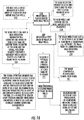
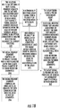
- Embodiments of the method include: detecting a first encoding signal and a second encoding signal for solid supports in a plurality of solid supports (e.g., a multiplexing bead set); comparing the first encoding signal and the second encoding signal for a respective solid support in the plurality of solid supports, wherein the second encoding signal for the respective solid support is detected during or after at least one chemical and/or physical change associated with the solid support and the first and second encoding signals for the respective solid support are different; and decoding the plurality of solid supports based at least in part on the comparison of the first and second encoding signals.
- a plurality of solid supports e.g., a multiplexing bead set
- Embodiments of the method further may include providing a plurality of molecular recognition elements (such as, e.g., antibodies, aptamers, and/or nucleic acid probes), at least some of the plurality of molecular recognition elements including one or more encoding agents; binding at least a portion of the plurality of molecular recognition elements to at least a portion of a sample on the solid support; detecting a first encoding signal and a second encoding signal for molecular recognition elements in the plurality of molecular recognition elements; comparing the first encoding signal and the second encoding signal for a respective molecular recognition element in the plurality of molecular recognition elements, wherein the second encoding signal for the respective molecular recognition element is detected during or after at least one chemical and/or physical change associated with the molecular recognition element and the first and second encoding signals for the respective molecular recognition element are different; and decoding the plurality of molecular recognition elements based at least in part on the comparison of the first and second
- the solid support may be a microscope slide holding a biological sample such as, e.g., a tissue section.
- the solid support may be a glass, silicon, or plastic slide holding arrays of proteins and/or nucleic acids involved in a direct or sandwich type of assay.
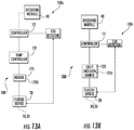
- An assay decoding system may include a circuit comprising at least one processor; a fluidic analysis chip comprising a plurality of solid supports (e.g., a multiplexing bead set); and a source in communication with the plurality of solid supports, wherein the circuit activates the source to cause at least one detectable physical and/or chemical change associated with at least some of the plurality of solid supports and compares first and second encoding signals for a respective solid support in the plurality of solid supports to decode different populations of solid supports in the plurality of solid supports.
- a circuit comprising at least one processor; a fluidic analysis chip comprising a plurality of solid supports (e.g., a multiplexing bead set); and a source in communication with the plurality of solid supports, wherein the circuit activates the source to cause at least one detectable physical and/or chemical change associated with at least some of the plurality of solid supports and compares first and second encoding signals for a respective solid support in the plurality of solid supports to decode different populations of
- the source may include at least one of a thermal source or a light source in communication with the plurality of solid supports, wherein the circuit activates the at least one of the thermal source or the light source to cause at least one detectable physical and/or chemical change associated with at least some of the plurality of solid supports.
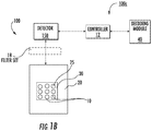
- the system may include a controller, a detector in communication with the controller, an image processor with a module configured to identify signal present in signal detection segments of reaction wells of a device holding the reaction wells at different points in time for a single sample, and a dynamic decoding module.
- the reaction wells can have at least one bead retention segment.
- the module can be configured to identify a positive assay signal after a reaction and later before and after at least one defined event.
- the module can be configured to carry out multiplexed bead decoding based on identified positive assay signals after a reaction event and before and after a defined event.
- Centerlines of bead wells holding respective beads can be spaced apart at a distance of between 0.2 and 1000 ⁇ m.
- the system may include a plurality of solid supports (e.g., a multiplexing bead set) including a first population of solid supports including at least one encoding agent at a first concentration and/or ratio; and a second population of solid supports including the at least one encoding agent at a second concentration and/or ratio and at least one additional encoding agent, wherein a fluorescence excitation and emission wavelength for the at least one encoding agent and the at least one additional encoding agent overlap, and wherein the first and second concentrations of the at least one encoding agent are different and the different concentrations and/or ratios of the at least one encoding agent on respective solid supports in the first and second populations provide a plurality of encoding states.
- a plurality of solid supports e.g., a multiplexing bead set
- the system further may include a plurality of encoded molecular recognition elements, wherein the plurality of encoded molecular recognition elements includes a first population of molecular recognition elements including at least one encoding agent at a first concentration and/or ratio; and a second population of molecular recognition elements comprising the at least one encoding agent at a second concentration and/or ratio and at least one additional encoding agent, wherein a fluorescence excitation and emission wavelength for the at least one encoding agent and the at least one additional encoding agent overlap, and wherein the first and second concentrations of the at least one encoding agent are different and the different concentrations and/or ratios of the at least one encoding agent on respective molecular recognition elements in the first and second populations provide a plurality of encoding states.
- an encoded molecular recognition element includes two or more (e.g., 2, 3, 4, or more) encoding agents.
- the present disclosure also envisages a kit comprising a plurality of solid supports as described herein.
- phrases such as “between X and Y” and “between about X and Y” should be interpreted to include X and Y.
- phrases such as “between about X and Y” mean “between about X and about Y.”
- phrases such as “from about X to Y” mean “from about X to about Y.”
- spatially relative terms such as “under,” “below,” “lower,” “over,” “upper” and the like, may be used herein for ease of description to describe one element or feature's relationship to another element(s) or feature(s) as illustrated in the figures. It will be understood that the spatially relative terms are intended to encompass different orientations of the device in use or operation in addition to the orientation depicted in the figures. For example, if the device in the figures is inverted, elements described as “under” or “beneath” other elements or features would then be oriented “over” the other elements or features.
- the exemplary term “under” can encompass both an orientation of "over” and “under.”
- the device may be otherwise oriented (rotated 90 degrees or at other orientations) and the spatially relative descriptors used herein interpreted accordingly.
- the terms “upwardly,” “downwardly,” “vertical,” “horizontal” and the like are used herein for the purpose of explanation only unless specifically indicated otherwise.
- microchip and “microfluidic chip” are used interchangeably and refer to a substantially planar, thin device.
- the microfluidic chip can be rigid, semi-rigid or flexible.
- the term “thin” refers to a thickness dimension that is 10 mm or less such as between 10 mm and 0.1 mm, and can be about 3 mm, about 2.5 mm, about 2 mm, about 1. 5 mm, about 1 mm, or about 0.5 mm.
- the microchip typically has a width and length that is less than about 6 inches, more typically between about 1 inch and 6 inches.
- the microchip can have a width dimension that is less than a length dimension.
- the microfluidic chip can have a width dimension that is about 2.13 inches (54 mm) and a length dimension that is about 3.4 inches (85.5 mm), in some embodiments.
- the microchip can include micro-sized and/or nano-sized fluidic channels.
- primary dimension refers to a width and/or depth dimension of a fluidic channel.
- micro-sized and “microfluidic” with respect to a fluidic channel refer to a fluid flow channel that has sub-millimeter or smaller size width and/or depth (e.g., the term includes micrometer and nanometer size channels) and includes channels with at least a segment having a width and/or depth in a size range of hundreds of microns or less, typically less than 900 microns and greater than 1 nm.
- a fluidic channel or portion thereof may include a nanochannel having a primary dimension between 1 nm and about 900 nm, more typically between about 10 nm and 500 nm.
- a channel of bead wells of a bead well array can have sidewalls and a floor formed into one or more substrates to have an open top surface and a closed bottom surface with the sidewalls extending therebetween.
- One or more spacers, top substrates, membranes or covers may be used.
- the top substrate, membrane or cover can seal, cover or otherwise close the upper surface of a fluidic channel(s) and/or array of reaction wells.
- the term "about” refers to parameters that can vary between +/- 20% or less, such as, e.g., +/-10% or 5%.
- solid support includes one or more of an object such as, e.g., a microbead, chip, plate, slide, pin, plate well, bead, microsphere, nanoparticle, microwell or other member that may be used to provide a probe and/or primer and/or that may be coupled to or labeled with an encoding agent (such as, e.g., a fluorescent compound, a chemiluminescent compound, a radioactive element, and/or an enzyme) and/or a dynamic element.
- an encoding agent and/or a dynamic element may be directly or indirectly attached to a solid support, such as, for example, by covalent attachment, noncovalent attachment, and/or physical incorporation.
- a solid support may be a printed array on a solid surface. In some embodiments, a solid support may be a microsphere. In some embodiments, a solid support may be a solid surface on which a sample, such as, e.g., a chemical and/or biological component (e.g., a tissue sample), is provided and a molecular recognition element comprising one or more encoding agent(s) may be attached to a portion of the sample.
- the molecular recognition element may comprise or may be an antibody, aptamer, DNA hybridization probe, oligonucleotide, peptide, protein, and/or combinations thereof.
- a solid support may comprise a labile reagent and/or support bond, each of which may allow for cleavage from the solid support.
- one or more encoding agents may be attached to a solid support (e.g., a bead or microsphere) to provide an encoded solid support (e.g., an encoded bead or encoded microsphere).
- one or more encoding agents may be attached to a molecular recognition element (e.g., an antibody) to provide an encoded molecular recognition element (e.g., an encoded antibody).
- an encoded molecular recognition element may be attached to a particle and/or may attach to a particle, such as, for example, a nanoparticle.
- an encoded molecular recognition element may attach to a solid surface on which a sample is provided due to the binding affinity of the encoded molecular recognition element to an element in and/or on the sample on the solid surface.
- an encoding agent may not be attached to a solid support until an assay is begun or complete or unless the encoded molecular recognition element binds to an element on and/or in a sample on a solid support. Accordingly, methods of the present invention may include providing or binding one or more encoding agents onto a solid support.
- methods of the present invention comprise providing a plurality of encoded molecular recognition elements and binding at least a portion of the encoded molecular recognition elements to a sample on a solid support.
- methods of the present invention may be used in fluorescence microscopy applications including, for example, immunofluorescence mapping of tissues, cells, and/or receptors and/or fluorescence in situ hybridization (FISH).
- beads refers to solid phase members such as particles, granules or microspheres, typically magnetic microspheres, that can be porous, superficially porous, or nonporous of material(s) such as, e.g., polymers, plastics, glass, silicon dioxide, metal or semimetal oxides (including but not limited to aluminum oxides, titanium oxides, zirconium oxides or other oxides), quantum dots, metal particles, and/or the like, which may be appropriate for use in the reaction wells.
- a multiplexing bead set may be provided comprising a plurality of beads (e.g., microspheres) that are uniquely encoded to distinguish one population of beads from another.
- circuit refers to an entirely hardware embodiment or an embodiment combining software and hardware.
- the analyte in a sample can be any analyte of interest from a sample including, for example, various mixtures including synthetic and/or biological macromolecules, nanoparticles, small molecules, DNA, nucleic acids/polynucleic acids, peptides, proteins and/or the like.
- the analyte can be one or more analyte molecules.
- the sample or analyte of a sample can include one or more polar metabolites such as, e.g., amino acids and/or charged molecules, peptides, and/or proteins.
- the sample and/or analyte may also or alternatively include molecules extracted from biofluids, blood, serum, urine, dried blood, cell growth media, lysed cells, beverages and/or food.
- the sample may also or alternatively include environmental samples such as water, air and/or soil.
- oligonucleotide refers to a nucleic acid sequence of at least about five nucleotides to about 500 nucleotides (e.g., 5, 6, 7, 8, 9, 10, 12, 15, 18, 20, 21, 22, 25, 30, 35, 40, 45, 50, 55, 60, 65, 70, 75, 80, 85, 90, 100, 125, 150, 175, 200, 250, 300, 350, 400, 450 or 500 nucleotides).
- an oligonucleotide can be from about 15 nucleotides to about 50 nucleotides, or about 20 nucleotides to about 25 nucleotides, which can be used, for example, as a primer in a polymerase chain reaction (PCR) amplification assay and/or as a probe in a hybridization assay or in a microarray.
- Oligonucleotides to be used in this invention can be natural or synthetic, e.g., DNA, RNA, PNA, LNA, modified backbones, etc., or any combination thereof as are well known in the art.
- Probes and primers can comprise oligonucleotides (including naturally occurring oligonucleotides such as DNA and synthetic and/or modified oligonucleotides) of any suitable length, but are typically from 5, 6, or 8 nucleotides in length up to 40, 50 or 60 nucleotides in length, or more.
- oligonucleotides including naturally occurring oligonucleotides such as DNA and synthetic and/or modified oligonucleotides of any suitable length, but are typically from 5, 6, or 8 nucleotides in length up to 40, 50 or 60 nucleotides in length, or more.
- Probes and/or primers may be immobilized on or coupled to a solid support such as, e.g., a bead, chip, pin, or microtiter plate well, and/or coupled to or labeled with an encoding agent such as, e.g., a fluorescent compound, a chemiluminescent compound, a radioactive element, and/or an enzyme.
- a solid support such as, e.g., a bead, chip, pin, or microtiter plate well
- an encoding agent such as, e.g., a fluorescent compound, a chemiluminescent compound, a radioactive element, and/or an enzyme.
- encoding agent refers to one or more agents (e.g., chemicals, proteins, etc.) associated with (e.g., applied to, attached to, bound to, compounded with, used to fabricate or create, etc.) a solid support and/or a material of the solid support and/or a material in contact with the solid support that provide and/or will generate an encoding signal for the respective solid support (which may be all or a portion thereof).
- agents e.g., chemicals, proteins, etc.
- one or more encoding agents provide and/or generate a detectable encoding signal that allows for differentiation of a solid support (e.g., bead) population or sub-population.
- one or more encoding agents may provide and/or generate a detectable encoding signal for an individual solid support (e.g., a bead) to which the one or more encoding agents are attached and/or one or more encoding agents may provide and/or generate a detectable encoding signal for a particular portion of a solid support to which the one or more encoding agents are attached (e.g., the portion of the solid support to which a molecular recognition element comprising the one or more encoding agents binds).
- an individual solid support e.g., a bead
- one or more encoding agents may provide and/or generate a detectable encoding signal for a particular portion of a solid support to which the one or more encoding agents are attached (e.g., the portion of the solid support to which a molecular recognition element comprising the one or more encoding agents binds).
- An encoding signal may be provided and/or generated by one or more encoding agents associated with a solid support and/or by the solid support itself and/or a material (e.g., compound) associated with the solid support.
- the encoding signal is a signal (e.g., an optical and/or electrical signal) that is generated by one or more encoding agents (e.g., chemicals, proteins, etc.) associated with (e.g., applied to, attached to, bound to, compounded with, used to fabricate or create, etc.) a solid support and/or by the solid support.
- a detectable encoding signal may be optically and/or electronically detectable, which may be perceived visually with the human eye and/or electronically read, detected, and/or obtained.
- the detectable encoding signal can comprise intensity, typically at or above a defined threshold value, a color (e.g., color hue, color intensity, and/or color value), a color and intensity, and/or a change in size, shape, and/or radioactivity.
- the detectable encoding signal comprises a luminescence intensity, which may include a fluorescence, phosphorescence, and/or chemiluminescence intensity.
- the encoding signal for a respective solid support may be detectable (e.g., detectable optically, electronically, electrochemically, electrostatically, magnetically, etc.) or may not be detectable.
- the encoding signal for a respective solid support (which may be all or a portion thereof) may change.
- the encoding signal for a respective solid support may change from detectable to not detectable, from not detectable to detectable, from a greater value to a lower value (e.g., from a greater signal amplitude, fluorescence intensity value, diameter, etc.), and/or from a lower value to a greater value.
- an encoding signal for a respective solid support may occur over time and/or may occur due to at least one chemical and/or physical change associated with the solid support.
- an encoding signal for a solid substrate may change and/or may be provided and/or generated by a change in the environment in which the solid support is present (e.g., a change in a solution in which the solid support and/or encoding agent is in contact with).
- an encoding signal for a solid support may change and/or may be provided and/or generated by a change in magnetic behavior, pH, light scattering, physical size (increase or decrease), shape, refractive index, solubility, light absorbance and/or emission intensity or maxima wavelengths shifts, conductivity, dielectric constant, viscosity, and radio emission from isotopic decay, and combinations of the above.
- Encoding state refers to a particular combination of encoding signals (detectable or not detectable) for a respective solid support in a plurality of solid supports, such as, for example two or more encoding signals for a particular solid support at two or more points in time, and/or to a particular combination of encoding signals (detectable or not detectable) for a particular portion of a solid support (e.g., a specific area or part of a sample on the solid support providing the particular combination of encoding signals).
- the particular encoding signal at two or more points in time may allow for differentiation and/or identification of a particular population or sub-population (e.g., a particular solid support (e.g., bead) population or sub-population).
- a particular population or sub-population e.g., a particular solid support (e.g., bead) population or sub-population.
- the particular encoding signal for the respective solid support at two or more points in time may be the same and/or may be different.
- Each encoding state may be unique from another encoding state and/or detectable (e.g., optically and/or electronically) and distinguishable from another encoding state to provide distinguishable populations.
- an encoding signal at a first point in time for a respective population may be the same as the encoding signal at the first point in time for a different population, but at a second point in time the encoding signals for the two populations may be different, such that the two populations may be distinguished and/or identified.
- the encoding signal for a first population and second population may start out at different levels (e.g., have different signal amplitudes or values) but end up at the same level.
- decoding refers to (typically electronic/programmatic) identification of different populations of a respective sample (including e.g., a sample of solid supports and/or a sample comprising a plurality of encoded molecular recognition elements) based at least in part on the encoding signal from encoded solid support(s) and/or encoded molecular recognition elements.
- decoding is based at least in part on comparing two or more encoding signals for a respective solid support (which may be all or a portion thereof) before, during and/or after at least one chemical and/or physical change associated with the respective solid support and/or by comparing two or more encoding signals at different points in time.
- decoding is based at least in part on comparing two or more encoding signals for an individual solid support before, during and/or after at least one chemical and/or physical change associated with the individual solid support and/or by comparing two or more encoding signals for the individual solid support at different points in time.
- a sample comprising a plurality of solid supports may comprise 6 different populations and, thus, 6 different encoding states. Detection and/or identification of one or more encoding signals can allow for the decoding of the sample to determine the identity of the particular solid support population.
- decoding is based at least in part on comparing two or more encoding signals for a particular portion of a solid support (e.g., a specific area or part of a sample on the solid support) before, during and/or after at least one chemical and/or physical change associated with that portion of the solid support and/or by comparing two or more encoding signals for that portion of the solid support at different points in time.
- a solid support e.g., a specific area or part of a sample on the solid support
- Different encoded molecular recognition elements may provide a plurality of encoding states and detection and/or identification of one or more encoding signals can allow for the decoding of the sample to determine the identity and/or location of a particular population, such as, e.g., the identity and/or location of an element that binds the encoded molecular recognition element for particular population.
- dynamic decoding or "time-domain encoding”, referred to interchangeably herein, refer to the (typically automated) analysis of encoding signals of a sample (including e.g., a sample of solid supports and/or encoded molecular recognition elements) based on a plurality (e.g., 2 or more) of measurements (typically from images) to obtain encoding signals of the solid support(s) over time.
- Different populations e.g., populations of solid supports or molecular recognition elements
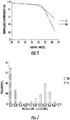
- time-domain encoding may incorporate photobleaching kinetics to decode different populations. By incorporating the time domain, time-domain encoding can unlock additional multiplexing levels that are unattainable by conventional decoding methods.
- Two or more measurements may be taken to obtain two or more encoding signals (e.g., 2, 3, 4, 5, 6, etc.) for respective solid supports in a sample comprising a plurality of solid supports and/or for a respective solid support with at least one portion of the solid support providing the two or more encoding signals.
- a first encoding signal measurement can be taken at a first point in time and a second encoding signal measurement can be taken at a second point in time.
- the first encoding signal measurement(s) can be based on a first image that is taken at the first point in time (e.g., before, during or after an assay is carried out e.g., after a hybridization reaction) and/or on the detection of an optical or electrical signal obtained at the first point in time.
- the second encoding signal measurement may be obtained after or later than the first point in time.
- the second encoding signal measurement and one or more subsequent measurements may be taken after any exited state lifetime of a compound (e.g., an encoding agent) associated with the solid support and/or at a time greater than 1 ms (e.g., 10 ms, 100 ms, or 1, 2, 3, 4, 5 second(s)) after the immediately preceding measurement.
- the second encoding signal measurement can be based on a second image taken at the second point in time and/or on the detection of an optical or electrical signal obtained at the second point in time.
- the two or more encoding signal measurements may be taken and/or obtained to detect the encoding signal at a point in time (e.g., at a first and second point in time) for a specific solid support in the sample of solid supports.
- an encoding signal measurement may be taken and/or obtained before, after, and/or during a Defined Event.
- Defined Event means a planned event that can cause or result in a physical and/or chemical change associated with a solid support.
- the Defined Event can be passive or dynamic.
- a Defined Event may cause or result in a physical and/or chemical change in a dynamic element.
- a Defined Event may cause or result in a physical and/or chemical change in an encoding agent (e.g. a dye, protein, etc.) and/or a solid support (e.g., a microsphere).
- an encoding agent e.g. a dye, protein, etc.
- a solid support e.g., a microsphere
- a “dynamic element” as used herein refers to a chemical and/or biological compound that provides or exhibits a physical and/or chemical change in response to a Defined Event.
- the physical and/or chemical change may modify the encoding signal for a respective solid support (which may be all or a portion thereof) at a point in time compared to the encoding signal at a different (e.g., earlier) point in time and may be detectable (e.g., optically and/or electrically detectable).
- a “dynamic element” may include an encoding agent (e.g. a dye, protein, etc.) and/or a solid support (e.g., a microsphere).
- the physical and/or chemical change may be a physical and/or chemical change that affects a solid support (e.g., the change may be a change in the charge and/or color of a solid support and/or may be a change in the size and/or shape of a solid support).
- the dynamic element may be the solid support and/or a compound attached and/or associated with the solid support.
- the physical and/or chemical change is a physical and/or chemical change that affects an encoding agent associated with the solid support (e.g., the change may be in the stability of a linker binding the encoding agent to the solid support, the solvent accessibility of an encoding agent, and/or the presence and/or absence of a quencher).
- the dynamic element may be the encoding agent and/or a compound attached to and/or associated with the encoding agent (e.g., a quencher).
- the physical and/or chemical change may be reversible or irreversible.
- the dynamic element may be an encoding agent.
- a Defined Event may selectively activate or deactivate an encoding agent.
- Example Defined Events are provided in Table 1. Table 1. Example Defined Events. • Addition/removal of a ligand, base pairing, quencher, etc.
- One or more Defined Events may be used to decode a solid support and/or a plurality of solid supports, and an encoding signal for a respective solid support (which may be all or a portion thereof) may or may not change in response to each of the one or more Defined Events.
- the Defined Event may not be one that typically occurs in an assay and/or analysis in which the solid support(s) are used in.
- the Defined Event is an event (e.g., a heating or light exposure) that occurs during an assay in which the solid support(s) are used in.
- a Defined Event may force a chemical and/or physical change in a portion of the solid support(s) (e.g., optionally in an encoding agent attached to and/or associated with the solid support), which can result in a change in the encoding signal for that portion of the solid support(s) that is associated with a particular encoding state.
- Example static encoding signals and time-domain encoding signals are provided in Table 2.
- a static encoding signal may be used to decode at least one population in a sample in addition to one or more time-domain encoding signals. Table 2.
- Example static encoding signals and time-domain encoding signals are provided in Table 2.
- Static Encoding Signals Time-domain Encoding Signals: Absorbance/Emission maxima wavelengths A change in Absorbance/Emission maxima wavelengths Emission Intensity A change in Emission Intensity Shape A change in Shape (cube to sphere, etc.) Size A change in Size (shrinkage, swelling, dissolution) Magnetic Properties A change in Magnetic Properties Presence of Radioactivity A change in Radioactivity (via natural decay or removal of the radioisotope) pH A change in pH Degree of Light Scattering A change in the Degree of Light Scattering Refractive Index A change in Refractive Index Conductivity A change in Conductivity Dielectric Constant A change in Dielectric Constant Any of the above Solubility (measured by a change of a static encoding parameter)
- an encoding signal is not to be confused with an assay dye signal, if present, and the dynamic element, encoding agent, and Defined Event should be configured and/or selected so that they do not interfere with the assay.
- the assay dye may be distinguishable from the one or more dynamic elements and/or encoding agents used in the dynamic decoding.
- the assay dye signal may be spectrally shifted from the signal associated with the dynamic element's signal and/or encoding agent's signal and/or the assay dye may use a detectable parameter different than the encoding agent(s) and/or dynamic element(s).
- the encoding agent and/or dynamic element may be spectrally similar and/or of the same magnitude and/or intensity of the assay dye; however, in such a case the Defined Event can cause a change in the encoding agent signal and/or dynamic element signal such that it is no longer spectrally similar and/or of the same magnitude and/or intensity of the assay dye and thus is distinguishable from the assay dye and/or no longer interferes with the assay.
- the same solid support in the same device e.g., fluidic device, typically the same beads which may be in the same reaction wells or virtual arrays
- the same encoding agents and/or dynamic elements for the different images can have similar spectral properties.
- a Defined Event may cause and/or result in one or more physical and/or chemical changes associated with a solid support.
- a Defined Event may cause and/or result in a change in an environment of the solid support, which can, in response, cause or induce a physical and/or chemical change in a dynamic element (e.g., an encoding agent and/or solid support) to provide a change in the encoding signal for the solid support (e.g., a change in the encoding signal for a particular solid support in a plurality of solid supports or a change in the encoding signal for a particular portion of a solid support, the solid support containing a plurality of encoding signals at different portions of the solid support), which can be visually and/or electronically detected (if the latter, the detection can be via an optical or electrical detector).
- a dynamic element e.g., an encoding agent and/or solid support
- Time-domain encoding may comprise comparing an encoding signal for a respective solid support at a particular point in time (e.g., prior to the Defined Event) to an encoding signal for the respective solid support at a different point in time (e.g., after the Defined Event) to identify the particular population the encoding signal and/or solid support belongs to.
- a first encoding signal for a respective solid support is obtained in a first reading (e.g., detection of an optical or electrical signal) and/or first image before or during a Defined Event and at least one second reading and/or second image is obtained after the first image to obtain a second encoding signal for the respective solid support.
- the first and/or second reading and/or image may comprise multiple different encoding signals that correspond to discrete solid supports or to discrete locations of and/or entities on and/or in a sample on a solid support.
- the different encoding signal measurements and/or images can be obtained from a common detector, e.g., when the fluidic device and/or solid supports of the fluidic device is or are held at the same temperature and the detector is operated at the same wavelength during an analysis of a sample.
- the different encoding signal measurements and/or images may be obtained within about 1 microsecond to about 50 hours of each other, and in some embodiments between about 1 ms to about 10 minutes of each other (e.g., 1 second to 1 minute or 1 second to about 10 minutes of each other).
- Two or more (e.g., 2, 3, 4, 5, 6, etc.) encoding signal measurements and/or images may be obtained before, during and/or after one or more Defined Event(s) and/or one or more physical and/or chemical change(s) associated with a solid support.
- the encoding signal measurements and/or images may be obtained using one or more wavelength bands (e.g., 1, 2, 3, 4, 5, etc.).
- two or more encoding signal measurements and/or images may be obtained before a Defined Event and/or at least one physical and/or chemical change associated with a solid support.
- a first image may be obtained in a blue excitation wavelength band
- a second image may be obtained in a green excitation wavelength band
- a third image may be obtained in a red excitation wavelength band, with each of the first, second and third images being obtained before a Defined Event and/or at least one physical and/or chemical change associated with a solid support.
- two or more encoding signal measurements and/or images may be obtained during and/or after a Defined Event and/or at least one physical and/or chemical change associated with a solid support.
- an image may be obtained in each of the following: a blue excitation wavelength band, a green excitation wavelength band, and a red excitation wavelength band, with each of the three images being obtained during and/or after a Defined Event and/or at least one physical and/or chemical change associated with a solid support.
- embodiments of the present invention may include obtaining multiple encoding signal measurements and/or images that may be obtained in multiple wavelength bands.
- two or more encoding signal measurements and/or images may be obtained before, during and/or after two or more Defined Event(s) and/or two or more physical and/or chemical change(s) associated with a solid support.
- a first image may be taken before a first Defined Event and/or a first physical and/or chemical change associated with a solid support
- a second image may be taken after the first Defined Event and/or the first physical and/or chemical change associated with a solid support
- a third image may be taken subsequent to the second image and after a second Defined Event and/or a second physical and/or chemical change associated with a solid support (optionally the same or a different solid support).
- the Defined Event can provide a physical and/or chemical change in a dynamic element that is, e.g., a thermally induced change (which may also be used for the assay), a pressure induced change, an optically induced change, a natural radioactive isotope decay, a chemically induced change, or combinations of any of the above.
- a thermally induced change which may also be used for the assay
- a pressure induced change which may also be used for the assay
- an optically induced change an optically induced change
- a natural radioactive isotope decay e.g., a chemically induced change, or combinations of any of the above.
- Time-domain encoding can exploit a defined stable, partially stable, selectively activatable, and/or unstable property (e.g., denaturation of an organic protein dye and/or an alteration in a chemical structure due to pH, heat or photosensitive labile bond, for example) of a respective encoding agent to force a change in the encoding signal, such as, e.g., the encoding signal for the solid support attached to the respective encoding agent or for the molecular recognition element attached to the respective encoding agent.
- unstable property e.g., denaturation of an organic protein dye and/or an alteration in a chemical structure due to pH, heat or photosensitive labile bond, for example
- the physical and/or chemical change can result in an increase or decrease in the intensity value, e.g., by at least 0.01% between the first and second images and/or readings, more typically an increase or decrease by at least 1-20% between the first and second images and/or readings.
- the increase or decrease can be sufficient to move the intensity level from high to low, low to high, medium to low, low to medium, high to medium or medium to high, zero to low, high or medium or high, low or medium to zero, for example.
- the terms high, medium, and low refer to a first, second and third level, respectively, where the first is greater than the second and third, the second is between the first and third, the third is less than the first and second.
- two or more different levels may be provided between the high and low levels (i.e., there may be more than one level between the high and low levels).
- the encoding agent can comprise a caged dye which is photosensitive and is selectively activated upon sufficient photo (light) exposure to increase intensity.
- similar spectral properties or “spectrally similar” as used herein refer to encoding agents (e.g., dyes) and/or dynamic elements that have similar excitation and/or emission wavelengths and generate detectable fluorescence intensities in response to a light source operated at a single wavelength or a single wavelength range or band pass such that they would be indistinguishable in an image and/or reading.
- encoding agents e.g., dyes
- dynamic elements that have similar excitation and/or emission wavelengths and generate detectable fluorescence intensities in response to a light source operated at a single wavelength or a single wavelength range or band pass such that they would be indistinguishable in an image and/or reading.
- quenching refers to deactivation of an excited molecular entity (e.g., an encoding agent) intermolecularly by an external environmental influence (such as a quencher) or intramolecularly by a substituent through a non-radiative process.
- a quencher is a molecular entity that deactivates (quenches) an excited state of an encoding agent, either by energy transfer, electron transfer, or by a chemical mechanism.
- the fluorescence intensity of at least one encoding agent and/or dynamic element may decrease after a quenching event as the Defined Event.
- the fluorescence intensity of at least one encoding agent and/or dynamic element may increase after the Defined Event.
- bleaching refers to the loss of absorption or emission intensity.
- PCR Polymerase chain reaction
- a nucleic acid sample e.g., in the presence of a heat stable DNA polymerase
- one oligonucleotide primer for each strand of the specific sequence to be detected under hybridizing conditions so that an extension product of each primer is synthesized which is complementary to each nucleic acid strand, with the primers sufficiently complementary to each strand of the specific sequence to hybridize therewith so that the extension product synthesized from each primer, when it is separated from its complement, can serve as a template for synthesis of the extension product of the other primer, and then treating the sample under denaturing conditions to separate the primer extension products from their templates if the sequence or sequences to be detected are present.
- Detection of the amplified sequence may be carried out by adding to the reaction product an oligonucleotide probe capable of hybridizing to the reaction product (e.g., an oligonucleotide probe to be used in the present invention), the probe carrying a detectable label, and then detecting the label in accordance with known techniques, or by direct visualization on a gel.
- the amplified sequence can also be detected by adding an intercalating dye to the reaction mixture and monitoring the fluorescence signal strength, which will be proportional to the total mass of double stranded DNA.
- RT-PCR reverse transcription PCR
- LAMP loop-mediated isothermal amplification
- DNA amplification techniques such as the foregoing can involve the use of a probe, a pair of probes, or two pairs of probes which specifically bind to DNA containing a polymorphism or mutation of interest, but do not bind to DNA that does not contain the polymorphism of interest under the same hybridization conditions, and which serve as the primer or primers for the amplification of the DNA or a portion thereof in the amplification reaction.
- probes are sometimes referred to as amplification probes or primers herein.
- reaction refers to any substance or compound, including primers, the nucleic acid template and the amplification enzyme, that is added to a system in order to bring about a chemical reaction, or added to see if a reaction occurs.
- Amplification reagents or reagent refer to those reagents (deoxyribonucleotide triphosphates, buffer, etc.) generally used for amplification except for primers, nucleic acid template and the amplification enzyme.
- amplification reagents along with other reaction components are placed and contained in a reaction vessel (test tube, microwell, etc.).
- magnetic as used herein includes ferromagnetic, paramagnetic and super paramagnetic properties.
- an oligonucleotide probe which is used to detect DNA containing a polymorphism or mutation of interest is an oligonucleotide probe which binds to DNA encoding that mutation or polymorphism, but does not bind to DNA that does not contain the mutation or polymorphism under the same hybridization conditions.
- the oligonucleotide probe is labeled with a suitable detectable group, such as those set forth below.
- Such probes are sometimes referred to as detection probes or primers herein.
- Fig. 1A is a schematic illustration of a fluidic analysis system 100 with a control circuit 100c comprising a controller 12, a detector 150 with at least one optical filter set 18 and a decoding module 40 configured to analyze encoding signals from solid supports 10 associated with an assay using a microfluidic device 20.
- Fig. 1B is an exemplary embodiment of another fluidic analysis system 100 with a control circuit 100c comprising a controller 12, a detector 150 with at least one optical filter set 18 and a decoding module 40, where the detector 150 can generate the Defined Event (e.g., optical excitement, photobleaching, etc.).
- This embodiment illustrates that no additional hardware components over conventional assay systems are required in contrast to other embodiments.
- the at least one optical filter set 18 can be configured to operate at a desired emission wavelength, such as, but not limited to, a single discrete range of wavelength and/or band pass, such as between about 10 nm to 1000 nm for excitation and imaging, and in particular embodiments for excitation about 545/30 nm and for imaging about 620/60 nm
- the optical filter set 18 may be configured to operate at a wavelength in the ultraviolet (UV) range (e.g., at a wavelength in a range of 400 nm to 10 nm), infrared (IR) range (e.g., at a wavelength in a range of 700 nm to 1 mm), and/or visible light range (e.g., at a wavelength in a range of 390 nm to 700 nm) and/or any range and/or individual value therein.
- UV ultraviolet
- IR infrared
- visible light range e.g., at a wavelength in a range of 390 nm to 700 n
- the optical filter set 18 may not be fluorescence-based and may be optics, such as, e.g., polarization filters, to detect changes in light scattering. If the change is sized-based, then no filters may be needed, but rather the ability to image and measure size.
- the microfluidic device 20 can have a bead well array 30 with an arrangement of bead wells 10 that hold respective beads 25.
- the controller 12 is also in communication with at least one device 125 (e.g., a thermal and/or light source) that can generate a Defined Event, which may change the environment of the beads 25 in the bead wells 10 for the dynamic decoding and/or may cause a physical and/or chemical change in the dynamic element.
- a device 125 e.g., a thermal and/or light source
- the decoding module 40 can include or be in communication with a correlation table and/or database of different populations associated with different encoding agents of defined bead populations.
- the device 125 can include a light source configured to emit light at a defined wavelength for a defined time to selectively activate, photoquench and/or photobleach beads 25 with one or more dynamic elements (e.g., encoding agents) responsive to same and/or a heat source configured to elevate the beads 25 to a critical temperature and/or a liquid source in fluid communication with the beads 25 in the bead wells 10 for altering the well environment and the like.
- the system 100 can be configured to evaluate recovery of the at least one detectable parameter after photobleaching. This recovery can be different for different materials/fluorophores in different environments and the differences can be exploited for decoding.
- the Defined Event may occur after a first image I 1 is obtained by the detector 150 and before a second image I 2 is obtained.
- the act of acquiring a first image I 1 can in and of itself be the Defined Event that results in a measureable change for the second image I 2 that is obtained after the first image I 1 .
- the Defined Event DE can generate a defined environmental change to, in and/or about the bead well array 30 such as at least one actively forced or applied thermal change T (which can be an increase or decrease in temperature, although typically an increase and can, e.g., exploit a thermal instability of a dynamic element (e.g., an encoding agent) at a defined temperature), a chemical change C, (e.g., a change in pH which can be introduced in a number of manners), and/or an optical change O, such as introduction of light, optionally at a defined wavelength of light and/or intensity, e.g., for exposure sufficient to provide a quenching action to exploit a photo-instability.
- a defined environmental change to, in and/or about the bead well array 30 such as at least one actively forced or applied thermal change T (which can be an increase or decrease in temperature, although typically an increase and can, e.g., exploit a thermal instability of a dynamic element (e.g., an encoding agent
- a second image I 2 can be obtained after the Defined Event DE.
- the system 100 can compare the intensity values 32s from the first and second images I 1 , I 2 to identify solid support (e.g., bead) populations/sub-populations.
- the second image I 2 can include stable (substantially unchanged) encoding signals 32ss and changed intensity values 32sc and this "fingerprint" or encoding signal(s) can be used for multiplexing the assay.
- the first image I 1 , second image I 2 and/or further images obtained subsequently in response to another Defined Event DE can be used in a multiplexed analysis to identify targets of a respective single sample.
- Additional Defined Events can be the same type, e.g., if temperature, then a higher temperature than the temperature at the first defined event can be used. Additional Defined Events may be a different type of Defined Event than that of a first or prior Defined Event, e.g. a temperature change after photobleaching. Additional Defined Events may cause changes in the same properties as preceding Defined Events, e.g. a change in temperature that results in decreased fluorescence intensity for some populations can follow a photobleaching event that results in decreased fluorescence intensity for the same and/or different populations of the solid supports. Alternatively or in addition, additional Defined Events may cause changes in properties of the solid supports that are different from the preceding Defined Events, e.g. a change in temperature that results in some populations of solid supports changing in size by either swelling or dissolving can follow a photobleaching event that resulted in decreased fluorescence intensity for the same and/or different populations of the solid supports.
- photostability differences between quantum dots (QD) and fluorescent organic dyes and/or fluorescent proteins can be used for encoding the solid supports, e.g., beads, particularly if both have similar spectral properties.
- QD quantum dots
- fluorescent organic dyes and/or fluorescent proteins can be used for encoding the solid supports, e.g., beads, particularly if both have similar spectral properties.
- photobleaching kinetics may be used to decode solid supports.
- Organic dyes can produce high fluorescence intensity but can be susceptible to photobleaching upon prolonged photoexposure.
- Quantum dots do not typically photobleach but rather tend to maintain or increase fluorescent emission following additional photoexposure. See, e.g., Bouzigues et al., Biological Applications of Rare-Earth Based Nanoparticles. ACS Nano 2011, 5, 8488-8505 ; and Wang et al., Luminescent nanomaterials for biological labelling. Nanotechnology 2006, 17, R1-R13 .
- a quantum dot is a nanoscale particle of semiconducting material that can be used for various experimental purposes, such as labeling proteins in conventional use.
- QDs of a defined wavelength e.g., about 605 nm
- OD organic dye
- FP fluorescent protein
- the organic dye (OD) can be a small molecule.
- a QD, organic dye and/or fluorescent protein can have different thermostabilites.
- QDs, ODs and/or FP can have similar fluorescence excitation/emission wavelengths.
- Non-limiting examples of excitation/emission wavelengths include 545/30 nm and 620/60 nm and can be imaged with a single filter set.
- Any quantum dot, fluorescent protein, and/or organic dye useful for luminescence (e.g., fluorescence) or other detectable parameter for time-domain encoding are contemplated by embodiments of the present invention.
- quantum dots that can be used in a method of the present invention include, but are not limited to, those including cadmium, indium, lead, sulfur, selenium, tellurium, zinc, and/or phosphorus, such as, e.g., CdS, CdSe, CdTe, InP, PbS, PbSe, and ZnS.
- organic dyes examples include, but are not limited to, fluorescein, Cy3 (Cy3.18), TAMRA, Texas Red (sulforhodamine 101), Nile Red, Cy5 (Cy5.18), Atto740, Cy7, Alexa Fluor 750, IR125 (ICG). See, e.g., http://www.fluorophores.tugraz.at/substance .
- fluorescent proteins include, but are not limited to, phycoerythrin, allophycocyanin, and green fluorescent protein (GFP).
- Beads or other solid supports can be encoded with an organic dye, a fluorescent protein (or protein dye), a QD, or a mixture of two or more of the same or different types (Mix) to produce comparable initial fluorescence signals. Beads or other solid supports can then be utilized in an assay, such as, e.g., the beads may be loaded into microfluidic microwell array devices, sealed with oil to isolate individual bead wells from their neighbors, and successively imaged before, after, and/or during a Defined Event. For example, referring to Fig.
- the temperature of a solid support may be held at a defined temperature, and a first image I 1 may be taken prior to a Defined Event, DEi, (e.g., prior to a 1 microsecond-50 hour photobleach, typically between about a 1 second to about a 3 minute photobleach) and second and third images I 2 and I 3 may be taken after the Defined Event, such as, e.g., after DEi and/or DE 2 .
- Photobleaching can be based on luminous energy, which can be delivered over any relevant or practical timescale, depending on the assay.
- Fig. 2B illustrates another embodiment for an exemplary thermal quenching and imaging sequence in which the temperature of a solid support, e.g., beads, is increased at least once to a defined threshold (critical temperature) value for a Defined Event, and a first image I 1 may be taken prior to the Defined Event (e.g., the first increase in temperature) and a second image I 2 may be taken once the temperature is returned to a set value (to have the same relative operating parameters for the detector).
- critical temperature refers to a temperature at which the physical and/or chemical change occurs for a dynamic element (e.g., an encoding agent).
- the Defined Event may include photoexposure (e.g., photobleaching) of the encoded solid support for a given period of time, such as, e.g., 1 microsecond or more, typically between about 1 second and 10 minutes such as, 5 seconds or more, such as, for example, 1, 5, 10, 15, 20, 25, 30, 35, 40, 45 seconds or 1, 2, 3, 4, 5, or more minutes.
- photoexposure e.g., photobleaching
- obtaining a first image, readout, and/or detecting of an optical or electrical signal of a solid support may be taken before an assay and the assay itself can generate the Defined Event (e.g., thermal and/or light exposure during the assay).
- the first image, readout, and/or detecting of an optical or electrical signal of a solid support can be taken after an assay is completed, but prior to a Defined Event, and the image, readout, and/or detecting may be used to determine initial fluorescence intensity and/or to serve as a reference for data normalization.
- Comparison of images, readouts, and/or signals before (including a reference image) and after a Defined Event can illustrate if a chemical and/or physical change associated with a solid support occurred following the Defined Event ( Figs. 3A-C ).
- Fig. 3A prior to photoexposure, in the image, beads encoded with FP, QDs, or a mixture of both produced comparable initial fluorescence signals that were indistinguishable as they have similar spectral properties.
- Fig. 3B after photoexposure, beads encoded with FP experienced significant bleaching over the course of 3 min while QD-encoded beads were unaffected by prolonged illumination as evidenced by their stable fluorescence over the same duration.
- Fig. 3B also shows that beads labeled with a mixture of both dyes exhibited moderate bleaching, less extensive than the FP-encoded population.
- “Indistinguishable” as used herein with reference to an encoding agent, dynamic element, and/or signal refers to a signal and/or parameter (e.g., a color, size, and/or intensity value (e.g., a fluorescence intensity value) at a given wavelength) that is within the standard deviation, confidence interval, and/or standard error of a population of supports for a given measurement system.
- a signal and/or parameter e.g., a color, size, and/or intensity value (e.g., a fluorescence intensity value) at a given wavelength
- the signal or parameter e.g., the intensity values for the fluorescence signals
- the signal or parameter e.g., the intensity values for the fluorescence signals
- each encoding state may be defined by a range of values due to variations in the measurements of encoded elements in a single population. This range may not be the standard deviation of the measurement of a single encoded element.
- a portion of the solid supports may have indistinguishable initial intensities and another portion of the solid supports may have distinguishable initial intensities.
- the solid supports may encode the same solid support population if the intensity values fall within the distribution range for that solid support population.
- Some embodiments include two or more different populations where the subpopulations have discrete and distinguishably different intensity levels, but these subpopulations may contain additional subpopulations that are only distinguishable after a Defined Event.
- Endpoint fluorescence decay values can be measured for each individual bead population.
- the endpoint fluorescence decay values were measured for the beads encoded with FP, OD, QDs, or a mixture of agents, and these values were then normalized to the initial bead intensity and sorted into histograms.
- Fig. 5 illustrates the distribution of intensities by bead type. The three different populations measured in this example were very well resolved from one another producing identification accuracies of >99.98%. This high resolution will allow beads combined together in a single sample to be readily identified without ambiguity once loaded into an array and dynamically decoded.
- a solid support and/or molecular recognition element may include one, two or more encoding agents in order to provide two or more, typically between about 2 to about 10,000 (or greater) different encoding signals representing different populations (e.g., about 2, 3, 4, 5, 6, 7, 8, 9, 10, 20, 50, 100, 200, 500, 1,000, 2,000, 3,000, 4,000, 5,000, 6,000, 7,000, 8,000, 9,000, 10,000, or more) that may be distinguished and/or identified using one or more Defined Events.
- Some embodiments include different populations (e.g., different solid support populations and/or different molecular recognition element populations) at or able to generate different fluorescence levels relative to each other using one or more Defined Events.
- a solid support may include a first encoding agent that corresponds to a first population and a second encoding agent that corresponds to a second population, the first and second encoding agents may be the same or different and each may have an initial fluorescence intensity level.
- the initial fluorescence intensity level for the first and second encoding agents is the same or substantially the same.
- the initial fluorescence intensity level for the first encoding agent is different than the initial fluorescence intensity level for the second encoding agent.
- Not all solid substrates are required to have an encoding agent or some populations may have a single dye. The dye may be stable and may not generate and/or exhibit a physical and/or chemical change for some solid substrate populations.
- Each of the first and second populations may include one or more subpopulations, such as described above, where each sub-population may have the same or substantially the same initial fluorescence intensity level.
- the term the "same or substantially the same" with respect to a fluorescence intensity level can, in some embodiments, refer to a variation of ⁇ 0.15 or less (e.g., ⁇ 0.1 or 0.05) for a normalized fluorescence intensity value and/or a value such that it remains within a defined range of a defined level, e.g., high, medium, low.
- a bead with an encoding agent may have a normalized fluorescence intensity value of 0.7 and beads having the same or substantially the same fluorescence intensity level may have a normalized fluorescence intensity value in a range of 0.55 to 0.85.
- a multiplexing assay e.g., a multiplexing bead-based bioassay
- a multiplexing assay e.g., a multiplexing bead-based bioassay
- the dynamic decoding methods produced at least six resolvable populations or encoding states.
- additional solid support (e.g., bead) populations at a single initial fluorescence intensity level may be provided.
- more bead populations at a single initial fluorescence intensity level may be provided by pre-sorting encoded beads.
- the approach may be expanded to other wavelengths without using a single, common detection wavelength for the analysis (e.g., 1, 2, 3, 4, 5, 6, 7, 8, 9, 10, or more different wavelengths or spectral bands or ranges) to increase the amount of multiplexing levels that could be achieved.
- incorporación of the time domain into solid support decoding strategies can be performed using strategies beyond differences in photostability of the different encoding dyes.
- an alternative or additional dynamic encoding strategy is to exploit the thermal stabilities of an encoding agent.
- a protein and/or organic dye can be susceptible to heat denaturation at elevated temperatures.
- QDs are semiconductor materials that are stable at elevated temperatures. These properties for these dyes can be utilized in dynamic decoding embodiments.
- Microspheres were labeled with FPs or QDs so that each population exhibited indistinguishable initial fluorescence. Each bead population was then loaded into microchips for imaging as previously described. Images were first acquired at 25 °C to determine the initial fluorescence intensity and also to serve as a reference for data normalization. Chips were then heated to elevated temperatures to denature the FP, then cooled back to 25 °C and imaged again. The loss of fluorescence intensity between the pre- and post-heating images allowed for the identity of the bead populations to be determined.
- Fig. 6 illustrates the decrease in normalized fluorescence signal upon heating the beads. A decrease in signal is observed as temperature is increased due to disruption of streptavidin-biotin bonds at temperatures ⁇ 70 °C.
- FP and QDs were conjugated to the beads via streptavidin-biotin chemistry. However at higher temperatures, FP begins to denature and its fluorescence drops significantly. This differential quenching can be used to identify differently encoded beads with good resolution ( Fig. 7 ).
- incorporation of a dynamic element i.e., the fluorescent protein (FP), which is denatured as the temperature changes over time
- FP fluorescent protein
- incorporation of a temperature change in the time domain may be used for PCR-based assays where heating elements are already in place for thermocycling, thereby requiring no additional components for thermally-resolved multiplexing.
- concentration of a dye on a solid support (e.g., a bead) and/or a buffer composition may be modified to accentuate and/or increase resolution between solid support populations and/or allow additional distinguishable populations to be produced and identified.
- a time domain measurement may be used to decode an encoded solid support (e.g., a bead set) where one or more compounds (e.g., dynamic elements such as encoding agents) have been added to a portion of the solid support (e.g., a subset of beads).
- the one or more compounds may be dynamic elements that provide a physical and/or chemical change in response to a Defined Event.
- the physical and/or chemical change may be an observable change.
- the one or more compounds may provide for a change in fluorescence signal that is observed over the course of a temperature change caused by a change of quantum efficiency of one or more of the compounds (e.g., encoding dyes).
- a heat-labile or photoactivated compound e.g. a photoactivated acid like triarylsulfonium/hexafluoroantimonate salt
- a change in chemical properties of the solid support e.g. pH
- an encoding agent e.g. fluorescein
- solid supports contained in reaction wells that either have or constitute sensors or electrodes or electrode arrays that are sensitive to pH or conductivity changes e.g. the Ion Torrent platform, https://www.thermofisher.com/us/en/home/brands/ion-torrent.html
- a portion of a plurality of solid supports may include labile attachment chemistries for one or more dynamic elements that, upon activation (e.g., temperature change, pH change, solvent addition/removal, etc.) provide a physical and/or chemical change that results when one or more of the encoding compounds is lost to the surrounding solution (e.g. FITC-biotin released from a streptavidin-coated bead upon heating, and detected in the fluid contained within the assay well).
- a mix of labile and non-labile e.g. heat-labile or photocleavable streptavidin-biotin bonds and stable covalent chemical bonds, respectively
- encoding agents may be used.
- Some embodiments include the use of encoding agents (e.g., dyes) as dynamic elements that have varying degrees of susceptibility to quenching agents (oxygen, dabsyl, Black Hole Quenchers, Iowa Black, etc.) so that upon addition or removal of such quenching agents, a different population (e.g., a bead population) can be identified.
- quenching agents oxygen, dabsyl, Black Hole Quenchers, Iowa Black, etc.
- the dynamic element may include a quencher and one or more compounds may be protected from the quencher (e.g., by encapsulation, binding to a protein, etc.) and this may be used to accentuate differences between dyes and allow for different populations to be identified.
- this can be affected in flow cytometry formats by the addition of a quencher into the sheath flow liquid after an initial read upstream in the system.
- An example flow cytometry system is shown in Fig. 20 in which measurements before and after photobleaching are depicted.
- a further example flow cytometry system is shown in Fig. 21 in which measurements before and after a pH shift are depicted.
- a pH, organic solvent strength, ionic strength, or other such property can change by the addition of the sheath flow to affect a detectable change in the solid supports' encoding properties
- methods for dynamic decoding solid support populations can employ the time domain in a chemical and/or biochemical assay.
- Example assays include, but are not limited to, immunoassays, nucleic acid hybridization arrays, PCR, RT-PCR, RT-qPCR, etc.
- Methods of the present invention may be used with solid supports, such as, e.g., beads and substrates that are not beads, such as printed arrays on a solid surface.
- a method of the present invention may include photoresist or "printed" barcode reagents where strips or sections of each particle may vary and thereby create a distinct population.
- Compounds that may be used in a method of the present invention include, but are not limited to, fluorophores, chromophores, photocleavable or photoactivated compounds, heat activated or heat cleavable compounds or functional groups, and/or compounds that incorporate radioactive isotopes or magnetic or electrically conductive elements.
- Solid supports may also be engineered to change conformation, shape, and/or other physical properties in response to a Defined Event by methods such as, but not limited to, the use of different polymers with different physical and thermal properties or varying the degree of crosslinking between polymer strands for certain populations.
- a method of the present invention is used to detect two or more different populations of nucleic acids after PCR.
- PCR has many applications, for example the detection of trace amounts of nucleic acids to determine the presence of disease causing organisms, gene expression, genotyping, genetic engineering or modification, and forensic science applications.
- PCR amplification provides outstanding target identification and quantification over a large range of analyte concentrations.
- simultaneous and quantitative analysis of many analytes by PCR has proven to be extremely challenging. Intercalating dye fluorescence-based detection is only capable of determining total dsDNA concentration and therefore concurrent analysis of multiple templates in a single reaction vessel is not possible using this detection method.
- Fluorescent probe technologies can be used for low-level multiplexing of reactions as each target can be amplified using a different color fluorescence probe as a signaling reporter. Probes are also sequence specific, reducing false positives from primer-dimer formation or nonspecific amplification.
- a typical method for multiplexing with either conventional microtiter plate or microfluidic real-time-PCR (rt-PCR) is to use a small number of reaction wells, each containing three different color probes.
- rt-PCR microfluidic real-time-PCR
- multiplexing by this method is ultimately limited, by instrumentation and spectral overlap between dyes, to four-color detection, with one color typically reserved for an internal standard dye.
- the present invention may provide a method of increasing the multiplexing of the assay.
- Fig. 8 shows a microfluidic device 20 with a bead well array 30 to be used in embodiments of the present invention.
- the device 20 can include freeze-thaw valves 22 with microfluidic channels 20ch in fluid communication with the bead well array 30.
- Figs. 9A, 9B, 10A, 10B, 11A, 11B, 12A and 12B examples of bead wells 10 with geometries for improved signal detection are shown.
- the solid substrates 25 can cooperate with conventional bead wells 10 having circular perimeters (typically cylindrical or conical wells) that are configured to hold a bead.
- bead wells 10 to be used in embodiments of the present invention have geometries with a bead retention segment 11 in fluid communication with a signal detection segment 15 that is adjacent the bead retention segment 11.
- the bead wells 10 can be provided in a relatively dense array 30 of closely spaced apart bead wells 10.
- the bead wells 10 can be aligned in rows and columns or be offset from each other.
- the bead wells 10 can be provided in a regularly repeating pattern, an irregular repeating pattern, or in other patterns.
- the term "dense" means that a footprint of a fluidic analysis device can have between about 100-6000 wells 10 per mm 2 and/or between 10,000 to 5,000,000 wells 10 per cm 2 , typically between about 6,000 to about 2,000,000 wells 10 per cm 2 , more typically between about 500,000 to about 2,000,000 wells 10 per cm 2 .
- Some or all of the neighboring wells 10 can have a separation distance of between 0.11-1,000 ⁇ m such as about 1 ⁇ m, 2 ⁇ m, 3 ⁇ m, 4 ⁇ m, 5 ⁇ m, 6 ⁇ m, 7 ⁇ m, 8 ⁇ m, 9 ⁇ m, 10 ⁇ m, 11 ⁇ m, 12 ⁇ m, 13 ⁇ m, 14 ⁇ m, 15 ⁇ m, 16 ⁇ m, 17 ⁇ m, 18 ⁇ m, 19 ⁇ m, 20 ⁇ m, 100 ⁇ m, 200 ⁇ m, 300 ⁇ m, 400 ⁇ m, 500 ⁇ m, 600 ⁇ m, 700 ⁇ m, 800 ⁇ m, 900 ⁇ m, 1000 ⁇ m or any fractional number therebetween, measured centerline to centerline of the neighboring bead retention segments 11.
- Some or all of the wells 10 can all be reaction wells 10 that cooperate with amplification reagents. Some or all of the wells 10 can process sub-pL reaction volumes.
- the signal detection segment 15 can optionally comprise a short and/or elongate fluidic channel 15ch that connects an end of the signal detection segment 15e with the bead retention segment 11.
- the signal detection segment 15 can include an end 15e that is spaced apart a distance "L" from the bead retention segment 11, typically by between 30% to about 10,000% (.3X to about 100X) of a diameter of a target bead, more typically between about .3X to about 10X of the diameter of a target bead.
- L can be between 1X and 5X the diameter of a target bead.
- the length L can be between about 1 to about 320 ⁇ m, more typically between 1 and 32 ⁇ m, and in particular embodiments can be between about 3.2 and 16 ⁇ m.
- a number with the letter "X" refers to a multiplier, one times (IX), ten times (10X) and the like.
- L can be between about 1 ⁇ m to about 100 ⁇ m, more typically between 1 and 20 ⁇ m, such as about 1 ⁇ m, about 2 ⁇ m, about 3 ⁇ m, about 4 ⁇ m, about 5 ⁇ m, about 6 ⁇ m, about 7 ⁇ m, about 8 ⁇ m, about 9 ⁇ m, about 10 ⁇ m, about 11 ⁇ m, about 12 ⁇ m, about 13 ⁇ m, about 14 ⁇ m, about 15 ⁇ m, about 16 ⁇ m, about 17 ⁇ m, about 18 ⁇ m, about 19 ⁇ m, and about 20 ⁇ m.
- the length L can be measured from a centerline of the bead retention segment 11 or from a line completing the diameter of the bead retention segment drawn over the channel 15c connecting the bead retention segment 11 with the end of the signal detection segment 15e.
- Figs. 10A and 10B illustrate that the signal detection segment 15 can optionally be configured as a narrow channel or "slit", typically having a width that is 25%-75% less than a width of the bead retention segment 11.
- Figs. 11A and 11B illustrates that the signal detection segment 15 can have an end portion that is arcuate 15a, with a radius of curvature less than that of the bead retention segment 11.
- the distance "d" between centerlines of the bead retention segment and the arcuate end 15e can be the same as the length "L" discussed above.
- Figs. 12A and 12B illustrate that the signal detection segment 15 can have an end that has an annular channel 17 surrounding an internal upwardly projecting member 19.
- the projecting member 19 can have a height sufficient to extend above the fluid in the annular channel 17 of the signal detection segment 15.
- This configuration can define a detectable signal comprising a portion with an annular shape.
- the new geometries of the bead wells 10 are believed to improve detection in microbead array-based technologies. These well geometries can be configured such that one area of the well 11 is for magnetic loading and bead retention, and another region of the well 15 can be used (primarily or only) for detection of a signal.
- a small volume of reagent fluid can be isolated in the wells 10 using a method such as immiscible fluid sealing or pushing against another surface such as a gasket or other substrate as is known to those of skill in the art.
- Figs. 10A, 10B, 11A, 11B, 12A and 12B other embodiments may include other geometries, typically configured so that the bead retention region 11 has a pocket or receptacle with an opening diameter that is between about 101 - 195% of the diameter of the bead 25, and may be between about 105% and 150% in some embodiments.
- the depth of the well in the bead retention region 11 can be between about 50% and 185% that of the bead diameter.
- the depth of the well 10 at some or all of the signal detection region 15 maybe the same, deeper or more shallow than the well at the bead retention segment 11.
- the depth may decrease as the channel 15ch travels away from the bead retention segment 11.
- the depth may increase as the channel 15ch travels away from the bead retention segment 11 toward the end of the signal detection segment 15.
- the walls of the well 10 may taper outwardly or inwardly in a direction into the well 10.
- Different wells 10 may have different volumetric capacities, geometrical shapes patterns and/or sizes.
- the signal detection segment or region 15 can have a channel 15ch such as a pocket or slit or other geometric shape into which a target bead cannot physically enter. Both regions 11, 15 are fluidically connected so that reagents and/or analytes released from the bead 25 can diffuse or otherwise mix throughout the common solution volume of the well 10. By spatially separating the bead 25 from the detection region 11, the contribution of bead fluorescence to the signal can be reduced or eliminated, improving signal to noise ratio.
- the geometries of the wells 10 can allow high, single occupancy loading of reaction wells 10 while increasing a respective reaction volume, potentially improving reaction efficiency.
- Fig. 13A illustrates an analysis system 100 with a Defined Event device 125 comprising at least one heater input 125h as the Dynamic Event applicator.
- the heater 125h can be a heating element residing under and/or over the array 30, an oven or heat gun or other appropriate heater.
- the thermal Defined Event input can be configured to elevate the temperature to above ambient temperature, typically to at least 1 degree above 25 degrees C, typically between about 35 °C and 200 °C.
- the heater 125h can apply the critical temperature to the array 30 for between 1 microsecond -50 hours, typically between about 1 second to about 5 minutes, in some embodiments.
- the solid supports 10 can return to ambient or room temperature and/or to about 25 °C or other temperature, typically to about the same temperature as that used for the decoding image taken before the Defined Event, before the detector 150 takes a post Defined Event image(s). Forced cooling or passive cooling may be used once the heat input is removed.
- Fig. 13B illustrates an analysis system 100 with a Defined Event device 125 comprising at least one light source 125l as the Dynamic Event applicator.
- the light source 1251 can be a single emitter that transmits light at a defined wavelength or wavelength range or may comprise a plurality of emitters at different wavelengths, wavelength ranges or a plurality of emitters at the same wavelength or wavelength range to cover a larger area, for example.
- the Defined Event input 125l can be configured to actively transmit light to the solid supports 10 for a suitable time, such as between about 1 microsecond to 50 hours, typically between 1 second and 5 minutes, as described above.
- Fig. 13C illustrates an analysis system 100 with a circuit 100c where the detector 150 is the Defined Event device, which includes associated light emission sources as known to those of skill in the art.
- a microfluidic device 20 may include a well array 30 with a plurality of wells 10.
- the wells 10 can hold beads 25 in the bead retention segments 11.
- the beads 25 can optionally comprise primers attached thereto and may optionally be pre-loaded into the bead retention segments 11 of the wells 10.
- the device 20 may comprise upper and lower substrates 50u, 50b ( Figs. 14B, 14C ) that attach together.
- the upper substrate 50u may be the same or different from the lower substrate 50b.
- Either or both substrates 50u can be rigid and comprise glass, quartz, silicon, or a suitable metal for example.
- Either or both substrates 50b may be polymeric, such as silicone or other polymeric material (such as PMMA, COC, COP, PDMS, PP, PE, PTFE, or Kapton (polyamide), among many others), and it can provide the array of bead wells 10.
- the upper or lower substrate 50u can have at least one port 50p in fluid communication with the wells 10.
- the reaction wells 10 can optionally be perpendicular to flow through the array chamber with the array of wells 30 during reagent filling and/or oil sealing, for example: however, other alignment configurations may be used.
- Fig. 14A shows that the microfluidic chip 20 can be configured so that the array of bead wells 30 occupy a footprint "F" (typically between 1 mm and 10 cm) with a dense array wells.
- the fluidic microchip 20 can include transport channel(s) for a sample and reagents or other chemical additions that can be in fluid communication with the array 30 as is well known to those of skill in the art.
- Fig. 14D illustrates an optional spacer 50s that may reside between the upper and lower substrates 50u, 50b.
- the spacer 50s can define sidewalls of some or all of a respective well 10.
- the spacer 50s can comprise a photoresist used as both a gasket and spacer.
- a sealing agent 75 such as sealing oil can separate adjacent wells 10 with beads 25 as is well known to those of skill in the art. Hydrophobic membrane(s) may also or alternatively be used.
- the sealing agent 75 e.g., oil
- the sealing agent 75 can extend over the top of the bottom substrate 50b.
- the sealing agent 75 can have a thickness or depth associated with the spacer/gasket 50s.
- the sealing agent 75 and can cover everything but the bead/reaction well 10.
- the sealing agent 75 can comprise mineral, silicone, hydrocarbon or fluorocarbon-based oil and/or waxes.
- the reaction solution 23, e.g., an aqueous solution does not typically touch the top substrate 50u.
- This technology may be particularly advantageous for bead-based assays involving amplification methods such as the polymerase chain reaction (PCR) or enzyme-linked immunosorbent assays (ELISA) that use fluorescence signal readout in analog or digital detection modes.
- PCR polymerase chain reaction
- ELISA enzyme-linked immunosorbent assays
- zero, one, or multiple analyte molecules are captured by a solid support, which may optionally comprise a bead such as a magnetic bead.
- the solid support can then be loaded into a microwell array 30 with a geometry that restricts the loading of the solid supports 25 to one or zero per well 10.
- a small volume of amplification reagents can be sealed in each reaction well 10 with the solid support 25, and a chemical reaction can be performed to produce a fluorescence signal if the analyte molecule is present.
- the assay fluorescence signal can then be measured, processed, and used to determine analyte concentration in the sample.
- Singleplex Reactions in a Compact Array is a massively parallel amplification and detection method using a microbead-array format that has the potential to perform, hundreds, thousands, millions or billions of isolated, singleplex rt-PCR reactions for many different target sequences simultaneously.
- SiRCA Compact Array
- U.S. Patent Application Serial Number 14/402,565 (patent no. 9,617,589 ), describing, for example, bead-based delivery of reagents for parallel assays on a multiplexed-in-space microfluidic device.
- the arrays 30 can be used with individual sets of biotinylated primers that are attached to dye encoded, streptavidin-labeled, magnetic microspheres or beads.
- a bead set library containing up to tens to hundreds of bead types can be made, each with a different primer set for a different target sequence, and new bead sets can be added to the bead mixture at will.
- the primers attached to the beads act as hybridization probes, capturing and purifying the nucleic acid sequence specific to that bead.
- Sample matrix interferents extraneous DNA, RNA, cell membrane components, etc.
- polymerase, dNTPs, and intercalating dye are added, and the beads are loaded into individual wells 10 and sealed from one another using an immiscible oil or hydrophobic membrane. Stochastically loading individual, encoded primer beads into separate microreaction wells can be accomplished in a matter of seconds to minutes, unlike hand pipetting or reagent printing.
- Magnetic loading of beads into optimized geometries can be more efficient than random isolation by dilution into droplets or reaction wells that do not contain regions designed for bead capture and/or a separate detection region for a well 10.
- the streptavidin/biotin interaction is very stable at temperatures below 50 °C; however, elevated temperatures used for denaturation during PCR may allow the subsequent release of the primers during the first rt-PCR cycle initiating amplification of target DNA.
- the chips were wet with ethanol, then water, and then blocked with loading buffer (20 mM Trizma, 50 mM KCl, 2.5 mM MgCh, 1% BSA, and 0.1% Tween 20).
- loading buffer (20 mM Trizma, 50 mM KCl, 2.5 mM MgCh, 1% BSA, and 0.1% Tween 20).
- Master mix (1x Platinum Quantitative PCR SuperMix-UDG with 0.0625 units/ ⁇ L additional Platinum Taq DNA polymerase, 0.5% BSA, 2.7 ⁇ M primers, gDNA from S. mutans, and 3x SYBR Green) was added to the chip and then Krytox GPL104 perfluorinated oil was pulled through the chip to seal the reaction volumes from one another.
- Embodiments of the invention can involve reaction wells 10 with geometries configured to contain more than one bead so that a reaction between reagents released from one or more beads and reacting in solution or upon the surface of one or more beads or any combination thereof can be studied at a designated detection region(s) as shown or alternatively upon a bead's surface.
- the bead well arrays 30 can include variations where some wells 10 hold one bead 25, some wells 10 hold two beads 25, and some wells 10 hold more than two beads 25 on a single substrate or fluidic device or on separate substrates or devices.
- Kits useful for carrying out the methods of the present invention can, in general, comprise one or more sets of beads having encoding agents and, optionally, reagents attached thereto for carrying out the methods as described above, such as restriction enzymes, optionally packaged with suitable instructions for carrying out the methods.
- the kits may also include containers for housing elements included therein. Such containers include, but are not limited to vials, microfluidic chips with bead well arrays and cartridges, including preloaded bead devices. Fig.
- the kit 500 may include one type/population of encoded beads 25 (i.e., beads that all have the same encoding signal or "fingerprint") or may include two or more different types/populations of encoded beads 25 (i.e., at least two different bead populations, one having a first encoding signal and one having a second encoding signal that is different than the first).
- the kit 500 may include the encoded beads 25 as a mixture in a single package or may separately package each encoded bead population (e.g., separately package the bead population with the first encoding signal and separately package the bead population with the second encoding signal).
- the beads 25 may have primers attached thereto.
- the primers may be a pair of biotinylated primers, and the beads 25 may be streptavidin-labeled such that binding of the biotinylated primers to the beads occurs.
- the beads 25 may include a marker, such as an optical marker, that may be used during analysis to identify the primers anchored to the respective beads 25. For example, different encoded beads of the same or different sizes may be marked for identification of different attached primer sets during analysis.
- Various pre-encoding methods may be used to provide a marker on the beads 25, including a predefined size, shape, magnetic property and/or fluorescence doping used alone or in combination with other encoding methods. Both custom-sequence biotinylated primers and streptavidin labeled paramagnetic magnetic beads can be readily purchased from commercial vendors or made in a suitable quantity in an appropriately equipped laboratory.
- microfluidic devices, beads and reaction methods described herein may be used in various other reactions, e.g ., where reagents are cleaved from a bead into a well to participate in a reaction.
- any nucleic acid transcription and/or amplification-related reaction is within the scope of the current invention, including but not limited to PCR reactions, real-time PCR (rt-PCR), digital PCR (dPCR), reverse transcription of RNA into cDNA (RT), PCR of cDNA from previous RT step (RT-PCR), RT-PCR using real-time or digital quantification, immuno-PCR (iPCR) and its variants, loop-mediated isothermal amplification (LAMP), rolling circle replication, and/or non-enzymatic nucleic acid amplification methods (e.g ., "DNA circuits").
- rt-PCR real-time PCR
- dPCR digital PCR
- RT reverse transcription of RNA into cDNA
- RT-PCR reverse transcription of RNA into cDNA from previous RT step
- RT-PCR PCR of cDNA from previous RT step
- RT-PCR PCR using real-time or digital quantification
- immuno-PCR iPCR
- LAMP loop-mediated isothermal
- ELISA enzyme-linked immunosorbent assays
- SiMoA single molecule array
- digital ELISAs ELISAs where the fluorogenic substrate is bound to the support surface to be cleaved at some point for subsequent reaction
- reactions in which multiple beads are used to deliver different reagents for combinatorial chemistry reactions where the beads deliver a catalyst reagent, and/or reactions where "click" chemistry reagents are delivered in stoichiometries determined by stochastic bead loading.
- Fig. 15 is a schematic illustration of an analysis system 100.
- the system 100 can include at least one controller 12 (typically comprising at least one processor) in communication with a signal detector 150 such as a camera or other imaging device.
- the signal detector 150 can be configured to detect a signal (e.g., an assay signal and/or an encoding signal) of the solid substrate(s) such as beads 25 in a bead well array 30 of a respective microfluidic chip 20 with an array of wells 30.
- the controller 12 can be in communication with an input device 125. Although shown as a separate device, the input device 125 can exist as a part of the system instrumentation. For example, the input device 125 can be the and/or a part of the optics system, imaging device, thermal device, etc.
- the controller 12 can be in communication with an image processor 211 having a signal detection with analysis module 221 (e.g., computer program) configured to identify if an assay signal is present in signal detection segments of the reaction wells and a decoding module 40 configured to obtain encoding signal(s).
- the image processor module 211 can be totally or partially onboard or remote from the controller and/or signal detector 150.
- the image processor module 211 can be configured to combine a plurality of post-assay images of the wells to assess whether a well has a positive readout.
- the image processor module 211 may remove the background noise from the bead retention segment of respective wells.
- the module 211 may be configured to identify the presence of a signal from the detection segment(s) of a respective well to identify whether a positive assay reaction occurred based on an assay readout 222.
- the detector 150 can also detect encoding signal(s) using a decoding readout 40R.
- FIG. 16 is a flow chart of example operations that can be used to carry out analysis methods according to embodiments of the present invention.
- a fluidic device with bead wells is provided (block 250 ) .
- An encoding signal is obtained from the wells while beads are retained in bead wells, which may include obtaining a first image of beads retained in the bead wells (block 260 ) .
- a physical and/or chemical change then occurs for at least some of the beads (block 272 ) .
- a second image is then obtained (block 274 ) .
- Different bead populations are distinguished by comparing the encoding signals from respective beads in the first and second images (block 276 ) .
- an encoding signal can be read from the bead containing segment (i.e. directly from the bead) to ascertain what reagent(s) and/or analyte the bead may contain. In this manner, the array can be decoded to determine the meaning of a positive or negative assay signal.
- Beads may be encoded by means known to those skilled in the art, including fluorescent dye staining by one or more dyes at one or more intensity levels, bead diameter, bead shape, or any combination of defined and/or observable or detectable properties. Beads may also be encoded by any of the methods described herein.
- the bead wells can be arranged as a dense array of bead wells that define reaction wells (block 252 ) .
- the bead wells can have a bead retention segment can have a geometry and diameter that is the same or greater than a diameter of the bead and the signal detection segment, where used, has a geometry with a width that is less than the diameter of the bead (block 254 ) .
- the signal detection segment can comprise an elongate channel that is narrower than the diameter of the bead and the bead well geometry may be configured to have one or more of (a) a slit, (b) asymmetrical circular perimeters spaced apart by an elongate channel, (c) a bulls-eye pattern (i.e., an elongate channel merging into an annular channel), (d) a plurality of spaced apart circular and/or curvilinear perimeters joined by at least one elongate channel extending therebetween (block 256 ) .
- the bead retention segment can be sized and configured to hold only a single magnetic bead (block 257 ) .
- the bead wells can contain one or more amplification reagent(s) (block 258 ) .
- the bead wells can have a detection segment that can be spaced apart a distance L of between .3X and 100X the diameter of a target bead, e.g., between 1 to 1000 ⁇ m, from the corresponding bead retention segment (block 259 ) .
- the signal can include a fluorescence signal (with a tail) if an analyte molecule is present (block 261 ) .
- Fig. 17 is a flow chart of a method of fabricating exemplary devices according to embodiments of the present invention.
- An array of wells is patterned (e.g., formed) in a substrate; the wells have a volumetric capacity of between 1 aL to 100 ⁇ L, more typically between 1fL and 1 ⁇ L, and one or more defined geometries in a defined footprint with linear dimensions between 1 mm and 10 cm, the defined geometries including a bead retention segment in fluid communication with a signal detection segment that is spatially separated from the bead retention segment (block 300 ) .
- the array of wells can be formed by etching into a substrate (block 302 ) .
- the array of wells can be molded into a substrate (block 304 ) .
- Other fabrication methods are contemplated, e.g., photolithography, FIB milling, embossing, stamping and the like.
- the bead wells may have a bead retention segment with a diameter in a range of about 10 nm and 5,000 ⁇ m, typically between about 3.1-3300 ⁇ m that merges into a channel with a width between about 2-3 ⁇ m with a length L of between .3X and 100X the diameter of a target bead, e.g., between 1-100 ⁇ m and/or between 1-10 ⁇ m, in some embodiments, forming the optional signal detection segment (block 306 ) .
- the wells can be reaction wells with one or more amplification reagents.
- the array of wells can be arranged in a density of 6000/mm 2 to about 10,000/mm 2 , typically about 6,000/mm 2 (block 312 ) .
- the array of wells can be provided in a density of between 6,000/cm 2 to about 5,000,000/cm 2 , more typically 6,000/cm 2 to about 2,000,000/cm 2 , (block 314 ) .
- the bead retention segment can have a perimeter with a width that is the same or within about 195% of a diameter of a target (e.g., magnetic) bead, e.g., between 101% and 195% or 150% of the diameter of a target bead (block 316).
- a target e.g., magnetic
- the wells can have a reaction volume of between 100-150 fL with a bead volume of 20 fL (block 318 ) .
- Fig. 18 is a flowchart of a method of evaluating an assay according to embodiments of the present invention.
- Assay signal is electronically detected from a plurality of reaction wells with beads (block 350 ) .
- the term "electronically” refers to all forms of machine based detection (not human vision) such as a camera, e.g., a CCD camera, a CMOS camera, an array of electrodes, a SEM, and the like.
- the signal can be an increase in intensity, fluorescence, one or more defined colors, a defined pixel parameter and the like, including a change in light scattering properties (transparence), a change in transmittance or absorbance, chemiluminescence or combinations of different parameters.
- a plurality of images are obtained including a first image and obtaining a subsequent image after a Defined Event to identify encoding signals to decode the assay to identify bead populations in the assay sample (block 370 ) .
- the reaction wells can optionally have signal readout segments, and the method can electronically detect assay signal from an array of bead wells, each having a signal readout segment spatially separated from the bead retention segment, after a reaction has occurred to identify positives (block 352 ) .
- the signal readout segments comprise an elongate channel with a width and/or depth that is less than a diameter of the bead retention segment(s) (block 354 ) .
- the signal readout segments comprise an annular fluid channel in fluid communication with the bead retention segment(s) (block 356 ) .
- the assay signal is for a PCR or ELISA-based assay (block 358 ) .
- Multiple primer sets can be screened against each other or against different reference genomes using the same size beads or different size beads, at least two beads being held by a single reaction well with two (optionally different size) bead retention segments and at least one separate readout segment(s) (block 360 ) .
- These beads may be encoded by any of the methods listed herein or those sources referenced herein.
- the assay signal can be for nucleic acid profiling of clinical or laboratory samples using a defined bead set (block 362 ) .
- a plurality of beads may include one or more populations of beads that can be identified using an encoding agent that physically and/or chemically changes in response to photoexposure at a given wavelength and may include one or populations of beads that can be identified using an encoding agent that physically and/or chemically changes in response to photoexposure at the same and/or a different wavelength and/or that changes in response to temperature and/or the chemical environment.
- the encoding signal generated by the encoding agent for a respective bead prior to the physical and/or chemical change may be different than the encoding signal generated by the encoding agent for the respective bead after the physical and/or chemical change
- a plurality of encoded beads may be provided that includes different bead populations/subsets that can be identified by comparing the fluorescence intensity from first and/or second encoding agents attached to each bead at a first point in time before a Defined Event and an additional point in time during and/or after the Defined Event.
- a first bead population may include a first encoding agent (e.g., FP, organic dye and/or quantum dot) attached thereto and a second bead population may include a second encoding agent (e.g., FP, organic dye and/or quantum dot) attached thereto.
- Additional bead populations may include both the first and second encoding agents attached thereto in different ratios (e.g., in a ratio of first encoding agent:second encoding agent of 25:75, 50:50, or 75:25). For example, a third population may have a ratio of 30:70, a fourth population may have a ratio of 50:50, etc.
- the first and second encoding agents may have the same and/or similar fluorescence excitation/emission properties and/or intensities such that the first, second, and additional bead populations are indistinguishable at the first point in time prior to the Defined Event. However, at least one of the encoding agents may not be stable with respect to the Defined Event.
- the first and second encoding agents may exhibit different fluorescence intensities, which allows for the two encoding agents to be distinguished.
- the first and second bead populations may be identified by comparing the fluorescence intensity before the Defined Event with the fluorescence intensity during and/or after the Defined Event.
- the additional bead populations may also be identified by the fluorescence intensity or change in fluorescence intensity after the Defined Event as the ratio provides different levels or a gradient of fluorescence intensities between the intensities for the first and second encoding agents.
- the number of additional bead populations that may be provided may depend on the number of additional fluorescence intensities that can be identified ( i.e., that are distinguishable) at a point in time during and/or after the Defined Event.
- Defined Events may be described below to cause physical and/or chemical changes that create different intensity levels for a given subpopulation, it should be noted that these resulting intensity levels are "different" as compared to that measured for that particular subpopulation before the Defined Event and may, in some cases, correspond to intensity levels that are similar to or the same as initial intensity levels or final intensity levels for other subpopulations that were distinguished from the given subpopulation by another distinguishable property either before, after, or during the Defined Event.
- comparison of the encoding signal for a particular bead at different points in time which may include points in time before, after, or during a Defined Event, may be used to distinguish the bead from another bead.
- Photostability of organic dyes in the time domain may be used to decode the plurality of encoded beads.
- a first bead population may include a first organic dye attached thereto and a second bead population may include a second organic dye attached thereto.
- Additional bead populations may include both the first and second organic dyes attached thereto in different ratios as described above.
- the first and second organic dyes may have the same and/or similar fluorescence excitation/emission properties and/or intensities such that the first, second, and additional bead populations are indistinguishable at the first point in time prior to the Defined Event.
- the first and second organic dyes may be susceptible to different levels of photobleaching upon exposure to light for a defined time, typically between about 30 seconds and five minutes, such as about 1 minute, about 2 minutes, about 3 minutes or more.
- the different bead populations have different fluorescence intensities.
- the first organic dye may be not as susceptible (i.e., more stable) to photobleaching compared to the second organic dye (i.e., the dynamic element) and the fluorescence intensity for the first organic dye may only reduce by 10% after 1 minute, whereas the fluorescence intensity for the second organic dye may reduce by 90% after 1 minute.
- the first and second bead populations may be identified by the fluorescence intensity after the Defined Event (i.e., photobleaching).
- the additional bead populations may also be identified by the fluorescence intensity after the defined event as the ratio provides different levels or a gradient of fluorescence intensities between the intensities for the first and second organic dyes.
- Photostability of an organic dye and quantum dot in the time domain may be used to decode the plurality of encoded beads.
- a first bead population may include an organic dye attached thereto and a second bead population may include a quantum dot attached thereto.
- Additional bead populations may include both the first organic dye and organic quantum dot attached thereto in different ratios as described above.
- the first organic dye and quantum dot may have the same and/or similar fluorescence excitation/emission properties and/or intensities such that the first, second, and additional bead populations are indistinguishable at the first point in time prior to the Defined Event.
- the first organic dye i.e., the dynamic element
- the quantum dot is not susceptible to photobleaching.
- the different bead populations have different fluorescence intensities.
- the fluorescence intensity for beads with only the first organic dye may by significantly reduced after a defined time, e.g., 1 minute, whereas the fluorescence intensity for beads with only the quantum dot may not be reduced after 1 minute.
- the first and second bead populations may be identified by the fluorescence intensity after the Defined Event (i.e., photobleaching).
- the additional bead populations may also be identified by the fluorescence intensity after the Defined Event as the ratio provides different levels or a gradient of fluorescence intensities between the intensities for the first organic dye and quantum dot.
- Thermal stability of an encoding agent may be used to decode the plurality of encoded beads by comparing the fluorescence intensity from first and/or second encoding agents attached to each bead at a first point in time before a thermal Defined Event and at an additional point in time during and/or after the thermal Defined Event.
- a first bead population may include a first encoding agent (e.g., organic dye and/or quantum dot) attached thereto and a second bead population may include a second encoding agent (e.g., organic dye and/or quantum dot) attached thereto.
- Additional bead populations may include both the first and second encoding agents attached thereto in different ratios as described above.
- At least one of the encoding agents may not be stable to an increase or decrease in temperature.
- an encoding agent i.e., the dynamic element
- the thermal Defined Event may cause a change and/or disrupt the chemical bonds associated with the encoding agent and/or bead, such as, e.g., the chemical bonds of a binding pair (e.g., streptavidin-biotin) attaching the encoding agent to the bead.
- the first and second encoding agents may exhibit different fluorescence intensities that allows for the two encoding agents to be distinguished.
- the first and second bead populations may be identified by the fluorescence intensity after the Defined Event (i.e., increase or decrease in temperature).
- the additional bead populations may also be identified by the fluorescence intensity after the Defined Event as the ratio provides different levels or a gradient of fluorescence intensities between the intensities for the first and second encoding agents.
- a thermal Defined Event may activate or deactivate an agent (e.g., a quencher) that affects the fluorescence intensity of at least one of the encoding agents (i.e., the dynamic element).
- an agent e.g., a quencher
- a heat-labile compound may be activated by a thermal Defined Event where the temperature is increased.
- the agent in response to the thermal Defined Event may interact with an encoding agent, no longer interact with the encoding agent, and/or may affect the chemical properties of the environment in which the encoding agent is present (e.g., change the pH), which may provide a change in the fluorescence intensity of the encoding agent.
- the first and second encoding agents may exhibit different fluorescence intensities that allows for the two encoding agents to be distinguished.
- the first and second bead populations may be identified by the fluorescence intensity after the defined event (i.e., increase or decrease in temperature).
- the additional bead populations may also be identified by the fluorescence intensity after the defined event as the ratio provides different levels or a gradient of fluorescence intensities between the intensities for the first and second encoding agents.
- An optical Defined Event may activate or deactivate an agent (e.g., a quencher) that affects the fluorescence intensity of at least one of the encoding agents (i.e., the dynamic element).
- an agent e.g., a quencher
- a photoactivated compound may be present with the encoded beads and may be activated by an optical Defined Event where light is exposed to the encoded beads and agent.
- the agent in response to the Defined Event may interact with an encoding agent, no longer interact with the encoding agent, and/or may affect the chemical properties of the environment in which the encoding agent is present (e.g., change the pH), which may provide a change in the fluorescence intensity of the encoding agent.
- the first and second encoding agents may exhibit different fluorescence intensities that allows for the two encoding agents to be distinguished.
- the first and second bead populations may be identified by the fluorescence intensity after the defined optical event (e.g., exposure to light of a given wavelength and/or wavelength range).
- the additional bead populations may also be identified by the fluorescence intensity after the Defined Event as the ratio provides different levels or a gradient of fluorescence intensities between the intensities for the first and second encoding agents.
- a chemical Defined Event may be used to identify different bead populations/subsets.
- a change in the chemical environment may cause a change in the fluorescence intensity of at least one of the encoding agents.
- the chemical Defined Event may cause and/or provide a change in pH of the bead environment, change the composition (e.g., remove and/or add a chemical/ingredient and/or change a solvent), activate or deactivate an agent (e.g., a quencher) that affects the fluorescence intensity of at least one of the encoding agents, and/or change the stability of a binding complex, which may cause a change in fluorescence intensity of the encoding agent.
- an agent e.g., a quencher
- the first and second encoding agents may exhibit different fluorescence intensities that allows for the two encoding agents to be distinguished.
- the first and second bead populations may be identified by the fluorescence intensity after the Defined Event.
- the additional bead populations may also be identified by the fluorescence intensity after the defined event as the ratio provides different levels or a gradient of fluorescence intensities between the intensities for the first and second encoding agents.
- an additional population e.g., a third population to those described in Examples 1-6 above may be identified if the Defined Event provides a fluorescence intensity that is exhibited after the Defined Event that was not present before the Defined Event and is different than the fluorescence intensity of the other bead populations.
- a third bead population may include an encoding agent that does not exhibit fluorescence at a first point in time before the Defined Event.
- the first, second, and third bead populations are indistinguishable at a first point in time using fluorescence intensity.
- the Defined Event may activate the fluorescence of the encoding agent so that after the Defined Event a third fluorescence intensity is provided that is different than that for the first and second bead populations.
- Table 3 shows a conventional fluorescence encoding scheme where three intensity levels (low, medium, and high) of two different color dyes (red and blue) are used to encode nine populations of solid supports.
- Table 3 shows a conventional fluorescence encoding scheme where three intensity levels (low, medium, and high) of two different color dyes (red and blue) are used to encode nine populations of solid supports.
- Table 3 shows a conventional fluorescence encoding scheme where three intensity levels (low, medium, and high) of two different color dyes (red and blue) are used to encode nine populations of solid supports.
- Table 3 shows a conventional fluorescence encoding scheme where three intensity levels (low, medium, and high) of two different color dyes (red and blue) are used to encode nine populations of solid supports.
- Table 3 shows a conventional fluorescence encoding scheme where three intensity levels (low, medium, and high) of two different color dyes (red and blue) are used to encode nine populations of solid supports.
- Table 3 shows a conventional fluorescence encoding scheme where
- Table 4 shows how encoding with four dyes (red stable, red unstable, blue stable, blue unstable i.e. only two total colors) using mixtures to obtain 6 different dynamic properties (Low that stay low, medium that stays medium, medium that bleaches low, high that stays high, high that bleaches medium, and high that bleaches low) for each color results in 36 different populations that can be distinguished using a measurement of only two colors (red and blue) and three intensities (low, medium, and high) before and after a Defined Event. Table 4.
- Table 5 shows a conventional encoding a scheme where two colors (red and blue), three intensities (low, medium, high), and two sizes (small and big) are used to encode 18 populations of substrates. It should be noted that the populations in Table 5 are similar to those in Table 3 , but by adding a bead size dimension with two levels (small and big), the number of available conventional encoding levels was doubled from 9 to 18. Table 5.
- Table 6 shows how the dynamic decoding approach described herein can be applied to further increase the number of distinguishable populations or encoding states by the addition of two dynamic dimensions related to bead size: an increase in size by swelling or a decrease in size by dissolving. This results in 54 different populations that can be distinguished based upon changes observed (or observed not to occur) after a Defined Event. This gain in potential multiplexing is achievable by measuring only two colors (red and blue) at three intensities (low, medium, and high), and four sizes (big, bigger, small, dissolves/not detected). This encoding scheme can be further expanded by the incorporation of any of the other methods described herein. Table 6.
- Figs. 20 and 21 show examples of instrumentation that is not array based but utilizes a flow cytometer to make a measurement of a bead before or after a Defined Event.
- solid supports are measured before and after illumination photobleaches an encoding agent or agents.
- Fig. 21 shows an example where solid supports are measured before and after a sheath flow or additional reagent stream is mixed into the stream containing the beads.
- This flow can contain an agent such as but not limited to a buffer of a different pH, solvent, or ligand that affects at least one encoding agent or the solid support structure to cause a physical and/or chemical change.
- a comparison of the optical properties of the solid supports before and after the Defined Event can be used to decode one population or subpopulation from another.
- Microspheres typically encoded using fluorescent dyes with different spectral properties and varying concentrations. However, practical limits exist on the number of dyes that can be spectrally resolved or the number of distinguishable intensity levels with each dye.
- a method was developed that incorporates photobleaching kinetics into bead decoding, unlocking additional multiplexing levels unattainable by conventional decoding methods. To demonstrate this technique, beads were encoded with two dyes having overlapping fluorescence excitation and emission wavelengths but different photostabilities.
- the method incorporated a dynamic element into the decoding process.
- the method described herein employs the photobleaching kinetics to distinguish bead populations. Two dyes with overlapping spectral properties, but different photostabilities, were utilized to encode beads that could then be differentiated based on simple photobleaching rate measurements. The methods reported here monitor photobleaching, which occurs on the seconds timescale for these experiments, significantly increasing the multiplexing capacity of bead-based assays without increasing the complexity of the analytical platform.
- Streptavidin-functionalized ProMag magnetic microspheres were purchased from Bangs Laboratories (Fishers, IN). R-phycoerythrin (PE) biotin conjugate and 605 Qdots (QDs) biotin conjugate (Life Technologies; Carlsbad, CA) were used as the encoding dyes for this study. "High" level beads were labeled with 5 nM PE, 250 nM QDs, or an 18 nM PE/ 22 nM QD mixture. The "low” level beads were labeled with 0.6 nM PE, 4 nM QDs, or a 0.45 nM PE/ 2 nM QD mixture. The buffer utilized throughout this encoding procedure was comprised of 1x Tris-buffered saline, pH 7.2 (Thermo Scientific; Waltham, MA) and 0.1% Tween 20 (Sigma Aldrich; St. Louis, MO).
- Microwell array chips for these studies were fabricated using silicon and glass. Silicon wafers were purchased from University Wafer (South Boston, MA) and coated with chromium and positive photoresist by NanoFilm (Westlake Village, CA). The array containing 3.5 ⁇ m diameter bead wells was photolithographically patterned onto the wafers using a Heidelberg Instruments DWL FS66 laser writer (Heidelberg, Germany). Following development of the photoresist and removal of the exposed chromium, wafers were etched in an Alcatel AMS 100 deep reactive ion etcher to a depth of ⁇ 5 ⁇ m. After etching, the remaining photoresist and chromium were removed from the wafer.
- SU-8 2050 (MicroChem; Westborough, MA) was then patterned onto the wafer to form the outer fluidic boundaries of the device.
- a glass substrate containing vias for fluid and bead access was aligned over the silicon array and epoxied into place (Loctite 120 HP).
- chips were treated with a 1% trichloro(octyl)silane (Sigma Aldrich) in heptane (Fisher Scientific; Pittsburgh, PA) to render the surfaces hydrophobic.
- Microchips were conditioned with a buffer containing 20 mM Tris, pH 8.0 (Life Technologies), 50 mMKCl (Life Technologies), 2.5 mM MgCl2 (Fluka; St. Louis, MO), 0.1% Tween 20, and 1% bovine serum albumin (Thermo Scientific). Beads were pipetted into a via and pulled over the array magnetically where uniform loading was achieved throughout the chip. Following loading, chips were sealed with Krytox oil (DuPont; Wilmington, DE) to isolate individual wells from each other. Sealed chips were kept in darkness until ready for imaging.
- Krytox oil DuPont; Wilmington, DE
- the imaging system utilized in these experiments was comprised of a Nikon AZ100 fluorescence microscope (Melville, NY), a Prior Scientific Lumen 200Pro fluorescence illumination system (Rockland, MA), and a Hamamatsu ORCA Flash 4.0 CMOS camera (Middlesex, NJ). Loaded chips were placed on the microscope stage and 2 s exposures were acquired every 2.5 s using Micro-Manager software. The excitation source shutter was fully open only during the exposure. Subsequent data plots in this manuscript display x-axis time points as real time (i.e. 2.5 s per image) rather than exposure time (i.e. 2 s per image). Images for both PE- and QD-encoded beads were acquired using a single filter set (545/30 nm excitation, 620/60 nm emission).
- Bead sets encoded with PE, QDs, or a mixture of both dyes were loaded into microwell array chips and repeatedly imaged. Inspection of the resulting images illustrated that beads underwent a differential change following prolonged imaging (see, e.g., Figs. 3A, 3B, and 3C ). As predicted, beads encoded with PE experienced significant reduction in fluorescence signal as the dye bleached over the course of 3 min while the fluorescence signal from the QD-encoded beads was largely unaffected by photoexposure over the same duration. Beads labeled with a mixture of both dyes exhibited a moderate decrease in fluorescence signal that was less severe than the PE-encoded population. A plot of the fluorescence decay profiles shows good resolution between each bead set. Very similar bleaching rates were observed within each bead population indicating high precision for this dynamic decoding approach.
- Fig. 22 illustrates the photobleaching profiles from the top and bottom 5% of beads from each population. These traces show that not only is the average decay of each bead population well-resolved from one another, but the range within each group is resolved as well. Fig. 22 also suggests that 3 min of photobleaching under these conditions is somewhat excessive since each population appears to be identifiable in a shorter time period.
- the maximum misidentification after 30 s of bleaching was 1.7%, occurring between the PE and Mix beads. While this error may be acceptable for certain applications where a small amount of misidentification is tolerable, it is too high for many digital, low LOD assays. In general, the percentage of bead misidentification should be less than the noise of the bioassay to ensure it does not significantly impact the measurement precision. Additionally, this short bleaching time required that 2.5% of both PE and Mix beads be excluded from the data set because they exhibited fluorescence in overlap regions between adjacent bead populations. Removing this fairly small percentage of beads was found to significantly improve identification accuracy and remove ambiguity from the analysis.
- Table 7 The percentages of beads in each population were sorted into three photobleaching bins ("fast”, “moderate”, and “slow") based on endpoint fluorescence decay. The percentage of misidentified beads diminished as bleaching time was increased. Beads exhibiting decay values in ambiguous overlap regions between populations were omitted ("excluded”) from the data sets.
- Standard encoding is typically based upon a single time point observation of wavelengths and intensities.
- the lowest level of fluorescence is the level 0, or non-encoded, where the presence of an encoding dye cannot be detected.
- i, j, and k represent intensity levels in excitation/emission bands I, J and K.
- the photostability of organic dyes in the time domain may be used to decode a biological sample.
- a first antibody may include a first organic dye attached thereto and a second antibody may include a second organic dye attached thereto.
- a third antibody may include both the first and second organic dyes attached thereto in different ratios as described above.
- the first and second organic dyes may have the same and/or similar fluorescence excitation/emission properties and/or intensities such that the first, second, and additional antibodies are indistinguishable at the first point in time prior to the Defined Event.
- the first and second organic dyes may be susceptible to different levels of photobleaching upon exposure to light for a defined time, typically between about 30 seconds and five minutes, such as about 1 minute, about 2 minutes, about 3 minutes or more.
- the different antibodies after photobleaching for the defined time, e.g., at least one microsecond, the different antibodies have different fluorescence intensities.
- the first organic dye may be not as susceptible (i.e., more stable) to photobleaching compared to the second organic dye (i.e., the dynamic element) and the fluorescence intensity for the first organic dye may only reduce by 10% after 1 minute, whereas the fluorescence intensity for the second organic dye may reduce by 90% after 1 minute.
- the first and second antibody populations may be identified by the fluorescence intensity after the Defined Event (i.e., photobleaching).
- the third antibody population may also be identified by the fluorescence intensity after the Defined Event as the ratio provides different levels or a gradient of fluorescence intensities between the intensities for the first and second organic dyes.
- a biological sample e.g., a tissue
- Each of the encoded antibodies may bind to a portion of the sample.
- the fluorescence intensity at different locations on the sample may be compared at different time points to identify the location of each antibody in and/or on the sample, and may be used to identify what elements are present in a sample and/or where the elements are in a sample.
Claims (18)
- Procédé de décodage de supports solides, comprenant :la détection d'un premier signal de codage et d'un deuxième signal de codage pour des supports solides respectifs dans une pluralité de supports solides, la pluralité de supports solides incluant deux populations différentes ou plus de supports solides, le premier signal de codage étant détecté à un premier point temporel et un deuxième signal de codage étant détecté à un deuxième point temporel, et la détection du premier signal de codage au premier point temporel et du deuxième signal de codage au deuxième point temporel pour des supports solides respectifs dans la pluralité de supports solides fournissant un nombre d'états de codage pour la pluralité de supports solides qui est supérieur au nombre de niveaux de codage à une mesure de point temporel unique, et le nombre d'états de codage étant supérieur au nombre de niveaux de codage à une mesure de point temporel unique ;la génération d'au moins un changement chimique et/ou physique associé aux supports solides dans la pluralité de supports solides qui est activé par une source de lumière et/ou une source thermique, le premier point temporel étant avant la génération de l'au moins un changement chimique et/ou physique associé aux supports solides et le deuxième point temporel étant pendant ou après la génération de l'au moins un changement chimique et/ou physique associé aux supports solides ;la comparaison du premier signal de codage pour un support solide individuel dans la pluralité de supports solides et du deuxième signal de codage pour le support solide individuel dans la pluralité de supports solides, les premier et deuxième signaux de codage pour le support solide individuel étant différents ; etle décodage de la pluralité de supports solides sur la base de la comparaison des premier et deuxième signaux de codage pour des supports solides respectifs dans la pluralité de supports solides afin d'identifier des supports solides correspondant à chacune des deux populations différentes ou plus de supports solides, le décodage de la pluralité de supports solides incluant la comparaison des premier et deuxième signaux de codage pour le support solide individuel afin de déterminer l'identité du support solide individuel.
- Procédé selon la revendication 1, dans lequel la pluralité de supports solides comprend au moins une population de supports solides pour lesquels le premier signal de codage n'est pas détectable et le deuxième signal de codage est détectable et/ou dans lequel la pluralité de supports solides comprend au moins une population de supports solides pour lesquels le premier signal de codage est détectable et le deuxième signal de codage n'est pas détectable.
- Procédé selon la revendication 1, dans lequel la pluralité de supports solides comprend au moins une population de supports solides pour lesquels le premier signal de codage a une valeur supérieure au deuxième signal de codage et/ou dans lequel la pluralité de supports solides comprend au moins une population de supports solides pour lesquels le deuxième signal de codage a une valeur supérieure au premier signal de codage.
- Procédé selon la revendication 1, dans lequel la pluralité de supports solides comprend au moins deux populations de supports solides qui ont différentes concentrations d'au moins un agent de codage sur des supports solides respectifs dans les au moins deux populations de supports solides, éventuellement
dans lequel la pluralité de supports solides comprend au moins deux populations de supports solides qui ont différentes concentrations et/ou différents taux de deux agents de codage ou plus sur des supports solides respectifs dans les au moins deux populations de supports solides, et au moins un parmi le premier signal de codage et le deuxième signal de codage pour une des au moins deux populations est détectable et distinguable du premier signal de codage ou du deuxième signal de codage de l'autre population. - Procédé selon la revendication 1, dans lequel l'au moins un changement chimique et/ou physique associé au support solide est un changement chimique et/ou physique dans le support solide et/ou un composé attaché au support solide, éventuellement dans lequel l'au moins un changement chimique et/ou physique associé au support solide est un changement chimique et/ou physique dans un agent de codage attaché à un support solide et/ou un composé attaché à l'agent de codage.
- Procédé selon la revendication 1, dans lequel la détection du premier signal de codage et/ou du deuxième signal de codage comprend l'obtention d'une mesure optique, éventuellement dans lequel l'obtention de la mesure optique comprend l'obtention d'une mesure d'émission de fluorescence pour la pluralité de supports solides.
- Procédé selon la revendication 1, comprenant en outre l'exposition de la pluralité de supports solides à une entrée optique, et dans lequel l'au moins un changement chimique et/ou physique a lieu pendant ou après l'exposition de la pluralité de supports solides à l'entrée optique.
- Procédé selon la revendication 1, comprenant en outre le photoblanchiment d'agents de codage attachés à au moins certains supports solides dans la pluralité de supports solides, et dans lequel l'au moins un changement chimique et/ou physique a lieu pendant ou après le photoblanchiment de la pluralité de supports solides.
- Procédé selon la revendication 1, comprenant en outre au moins une mesure parmi un chauffage ou un refroidissement de la pluralité de supports solides, et dans lequel l'au moins un changement chimique et/ou physique a lieu pendant ou après l'au moins une mesure parmi un chauffage ou un refroidissement de la pluralité de supports solides.
- Procédé selon la revendication 1, dans lequel la détection du deuxième signal de codage comprend l'obtention du deuxième signal de codage à un temps supérieur à 1 ms après que le premier signal de codage a été détecté, éventuellement dans lequel le deuxième signal de codage est obtenu à un temps qui est inférieur à 5 minutes après que le premier signal de codage a été obtenu.
- Procédé selon la revendication 1, dans lequel la détection des premier et deuxième signaux de codage comprend la détection continue de signaux de codage pour la pluralité de supports solides pendant une période de temps.
- Procédé selon la revendication 1, comprenant en outre la mesure d'un changement du taux d'extinction de fluorescence d'un agent de codage attaché à un support solide dans la pluralité de supports solides.
- Procédé selon la revendication 1, dans lequel la pluralité de supports solides comprend au moins une population qui a des supports solides codés avec au moins deux agents de codage qui ont des bandes d'excitation de fluorescence et des bandes d'émission de fluorescence en chevauchement, éventuellement dans lequel les au moins deux agents de codage ont différentes photostabilités et/ou dans lequel au moins un parmi les au moins deux agents de codage est stable et l'autre est instable.
- Procédé selon la revendication 1, comprenant en outre la génération d'un premier changement chimique et/ou physique associé à un premier support solide dans la pluralité de supports solides afin de définir une première population dans la pluralité de supports solides, et la génération d'un deuxième changement chimique et/ou physique associé à un deuxième support solide dans la pluralité de supports solides afin de définir une deuxième population dans la pluralité de supports solides, éventuellement dans lequel la génération du premier et/ou deuxième changement chimique et/ou physique comprend un photoblanchiment et/ou une dénaturation d'un agent de codage associé au support solide.
- Procédé selon la revendication 14, dans lequel la génération du premier et/ou deuxième changement chimique et/ou physique a lieu en même temps et/ou en utilisant les mêmes conditions, ou dans lequel la génération du premier et/ou deuxième changement chimique et/ou physique a lieu à des temps différents et/ou en utilisant des conditions différentes.
- Procédé selon la revendication 1, dans lequel le nombre d'états de codage pour la pluralité de supports solides est d'au moins six.
- Système de décodage d'essais (100), comprenant :un circuit (100c) comprenant au moins un processeur ;une puce d'analyse fluidique (20) comprenant une pluralité de supports solides, la pluralité de supports solides incluant au moins deux populations différentes de supports solides ;au moins une source parmi une source thermique ou une source de lumière (125) en communication avec la pluralité de supports solides ; etun détecteur (150) en communication avec le circuit et configuré pour détecter des premier et deuxième signaux de codage pour un support solide respectif dans la pluralité de supports solides,dans lequel le circuit est configuré pour activer l'au moins une source parmi la source thermique ou la source de lumière afin de provoquer au moins un changement physique et/ou chimique détectable associé à au moins certains dans la pluralité de supports solides, et pour comparer des premier et deuxième signaux de codage pour un support solide respectif dans la pluralité de supports solides afin de décoder les au moins deux populations différentes de supports solides dans la pluralité de supports solides, dans lequel le détecteur est configuré pour détecter le premier signal de codage à un premier point temporel et le deuxième signal de codage à un deuxième point temporel, le premier point temporel étant avant l'au moins un changement physique et/ou chimique détectable et le deuxième point temporel étant pendant ou après le changement physique et/ou chimique détectable.
- Système de décodage d'essais selon la revendication 17, dans lequel la pluralité de supports solides comprend :une première population de supports solides comprenant au moins un agent de codage à une première concentration et/ou un premier taux ; etune deuxième population de supports solides comprenant l'au moins un agent de codage à une deuxième concentration et/ou un deuxième taux et au moins un agent de codage supplémentaire,dans lequel une longueur d'onde d'excitation et d'émission de fluorescence pour l'au moins un agent de codage et l'au moins un agent de codage supplémentaire se chevauchent,dans lequel les première et deuxième concentrations de l'au moins un agent de codage sont différentes et les différentes concentrations et/ou les différents taux de l'au moins un agent de codage sur des supports solides respectifs dans les première et deuxième populations fournissent une pluralité d'états de codage.
Priority Applications (1)
| Application Number | Priority Date | Filing Date | Title |
|---|---|---|---|
| EP21183583.0A EP3957996A1 (fr) | 2015-10-05 | 2016-10-05 | Dispositifs fluidiques, kits et supports solides pour des procédés de décodage pour essais en multiplexage |
Applications Claiming Priority (2)
| Application Number | Priority Date | Filing Date | Title |
|---|---|---|---|
| US201562237324P | 2015-10-05 | 2015-10-05 | |
| PCT/US2016/055407 WO2017112025A2 (fr) | 2015-10-05 | 2016-10-05 | Procédés de décodage pour essais en multiplexage et dispositifs fluidiques, kits et supports solides associés |
Related Child Applications (1)
| Application Number | Title | Priority Date | Filing Date |
|---|---|---|---|
| EP21183583.0A Division EP3957996A1 (fr) | 2015-10-05 | 2016-10-05 | Dispositifs fluidiques, kits et supports solides pour des procédés de décodage pour essais en multiplexage |
Publications (2)
| Publication Number | Publication Date |
|---|---|
| EP3329279A2 EP3329279A2 (fr) | 2018-06-06 |
| EP3329279B1 true EP3329279B1 (fr) | 2021-07-07 |
Family
ID=58609951
Family Applications (2)
| Application Number | Title | Priority Date | Filing Date |
|---|---|---|---|
| EP16858484.5A Active EP3329279B1 (fr) | 2015-10-05 | 2016-10-05 | Procédés de décodage pour essais en multiplexage et dispositifs fluidiques, kits et supports solides associés |
| EP21183583.0A Pending EP3957996A1 (fr) | 2015-10-05 | 2016-10-05 | Dispositifs fluidiques, kits et supports solides pour des procédés de décodage pour essais en multiplexage |
Family Applications After (1)
| Application Number | Title | Priority Date | Filing Date |
|---|---|---|---|
| EP21183583.0A Pending EP3957996A1 (fr) | 2015-10-05 | 2016-10-05 | Dispositifs fluidiques, kits et supports solides pour des procédés de décodage pour essais en multiplexage |
Country Status (5)
| Country | Link |
|---|---|
| US (2) | US11016084B2 (fr) |
| EP (2) | EP3329279B1 (fr) |
| JP (1) | JP6847934B2 (fr) |
| CN (2) | CN108351352B (fr) |
| WO (1) | WO2017112025A2 (fr) |
Families Citing this family (4)
| Publication number | Priority date | Publication date | Assignee | Title |
|---|---|---|---|---|
| WO2019089996A1 (fr) * | 2017-11-03 | 2019-05-09 | University Of Washington | Amplification d'acide nucléique numérique à l'aide de particules codées |
| CN112236512A (zh) | 2018-11-13 | 2021-01-15 | 北卡罗来纳-查佩尔山大学 | 具有微流体装置的分析系统、微流体装置和相关方法 |
| DE102019220017A1 (de) * | 2019-12-18 | 2021-06-24 | Robert Bosch Gesellschaft mit beschränkter Haftung | Aufnahmeeinheit zum Aufnehmen eines Fluids, Verfahren und Vorrichtung zum Herstellen einer Aufnahmeeinheit, Verfahren und Vorrichtung zum Betreiben einer Aufnahmeeinheit und Aufnahmeeinrichtung |
| EP4221894A1 (fr) * | 2020-10-27 | 2023-08-09 | Quantum-si Incorporated | Système de détection simple molécule utilisant des informations de photoblanchiment |
Citations (5)
| Publication number | Priority date | Publication date | Assignee | Title |
|---|---|---|---|---|
| WO2000073777A1 (fr) * | 1999-05-28 | 2000-12-07 | Bioarray Solutions, Llc | Cytometrie de jeux ordonnes d'echantillons |
| WO2002099982A2 (fr) * | 2001-03-01 | 2002-12-12 | Illumina, Inc. | Procedes permettant d'ameliorer la detection d'un signal provenant d'un reseau |
| WO2004034012A2 (fr) * | 2001-10-18 | 2004-04-22 | Virtual Arrays, Inc. | Particules codees pour analyse multiplexee d'echantillons biologiques |
| WO2008122051A1 (fr) * | 2007-04-02 | 2008-10-09 | Acoustic Cytometry Systems, Inc. | Procédés et dispositifs pour l'analyse amplifiée de cellules et particules focalisées sur champ |
| US20100055721A1 (en) * | 2004-03-30 | 2010-03-04 | California Institute Of Technology | Surface Enhanced Raman Scattering and Multiplexed Diagnostic Assays |
Family Cites Families (29)
| Publication number | Priority date | Publication date | Assignee | Title |
|---|---|---|---|---|
| US4965188A (en) | 1986-08-22 | 1990-10-23 | Cetus Corporation | Process for amplifying, detecting, and/or cloning nucleic acid sequences using a thermostable enzyme |
| US4683202A (en) | 1985-03-28 | 1987-07-28 | Cetus Corporation | Process for amplifying nucleic acid sequences |
| US4683195A (en) | 1986-01-30 | 1987-07-28 | Cetus Corporation | Process for amplifying, detecting, and/or-cloning nucleic acid sequences |
| ES8706823A1 (es) * | 1985-03-28 | 1987-06-16 | Cetus Corp | Un procedimiento para detectar la presencia o ausencia de al menos una secuencia especifica de acidos nucleicos en una muestra |
| US4800159A (en) | 1986-02-07 | 1989-01-24 | Cetus Corporation | Process for amplifying, detecting, and/or cloning nucleic acid sequences |
| US6327410B1 (en) * | 1997-03-14 | 2001-12-04 | The Trustees Of Tufts College | Target analyte sensors utilizing Microspheres |
| US20030027126A1 (en) * | 1997-03-14 | 2003-02-06 | Walt David R. | Methods for detecting target analytes and enzymatic reactions |
| US7622294B2 (en) * | 1997-03-14 | 2009-11-24 | Trustees Of Tufts College | Methods for detecting target analytes and enzymatic reactions |
| US6023540A (en) * | 1997-03-14 | 2000-02-08 | Trustees Of Tufts College | Fiber optic sensor with encoded microspheres |
| US6143496A (en) | 1997-04-17 | 2000-11-07 | Cytonix Corporation | Method of sampling, amplifying and quantifying segment of nucleic acid, polymerase chain reaction assembly having nanoliter-sized sample chambers, and method of filling assembly |
| US7348181B2 (en) * | 1997-10-06 | 2008-03-25 | Trustees Of Tufts College | Self-encoding sensor with microspheres |
| US7115884B1 (en) * | 1997-10-06 | 2006-10-03 | Trustees Of Tufts College | Self-encoding fiber optic sensor |
| EP2360271A1 (fr) * | 1998-06-24 | 2011-08-24 | Illumina, Inc. | Décodage de capteurs de réseau avec des microsphères |
| CA2359352C (fr) | 1999-02-09 | 2004-09-21 | Illumina, Inc. | Traitement informatise d'informations dans des groupements ordonnes de maniere aleatoire |
| CN1329032C (zh) | 2000-07-26 | 2007-08-01 | 塔罗制药工业有限公司 | 非镇静巴比土酸盐化合物用作神经保护剂 |
| US8697029B2 (en) * | 2002-04-18 | 2014-04-15 | The Regents Of The University Of Michigan | Modulated physical and chemical sensors |
| CN1784590B (zh) * | 2003-03-07 | 2010-11-24 | 新泽西医学与牙科大学 | 可光学解码的微载体,阵列和方法 |
| WO2004101130A2 (fr) * | 2003-05-13 | 2004-11-25 | Affymetrix, Inc. | Systeme, procede et produit fournissant un faisceau d'excitation accordable en longueur d'onde |
| US7141378B2 (en) | 2004-07-02 | 2006-11-28 | Blueshift Biotechnologies, Inc. | Exploring fluorophore microenvironments |
| EP2017354A1 (fr) * | 2007-07-20 | 2009-01-21 | Eppendorf Ag | Détection et/ou quantification des molécules cibles d'un support solide |
| US8222047B2 (en) | 2008-09-23 | 2012-07-17 | Quanterix Corporation | Ultra-sensitive detection of molecules on single molecule arrays |
| US8236574B2 (en) | 2010-03-01 | 2012-08-07 | Quanterix Corporation | Ultra-sensitive detection of molecules or particles using beads or other capture objects |
| WO2011109379A1 (fr) | 2010-03-01 | 2011-09-09 | Quanterix Corporation | Procédés et systèmes pour étendre la plage dynamique dans des dosages pour la détection de molécules ou de particules |
| SE536884C2 (sv) * | 2010-03-15 | 2014-10-21 | Int Truck Intellectual Prop Co | Högspänningsförreglingskrets som använder seriell kommunikation |
| EP4361607A2 (fr) * | 2012-02-03 | 2024-05-01 | California Institute of Technology | Codage et décodage de signaux dans des dosages biochimiques multiplexés |
| WO2013176767A1 (fr) | 2012-05-25 | 2013-11-28 | The University Of North Carolina At Chapel Hill | Dispositifs microfluidiques, supports solides pour réactifs et procédés associés |
| IN2014MN02559A (fr) | 2012-06-22 | 2015-07-24 | Univ Macquarie | |
| JP6869949B2 (ja) | 2015-07-22 | 2021-05-12 | ザ ユニバーシティ オブ ノース カロライナ アット チャペル ヒルThe University Of North Carolina At Chapel Hill | 氷核形成剤を含む凍結融解バルブを備える流体装置と関連の操作及び分析方法 |
| CN108025304B (zh) | 2015-07-22 | 2022-01-21 | 北卡罗来纳-查佩尔山大学 | 含有具有空间分离的珠保留和信号检测段的珠孔几何结构的流体装置和相关方法 |
-
2016
- 2016-10-05 WO PCT/US2016/055407 patent/WO2017112025A2/fr active Application Filing
- 2016-10-05 EP EP16858484.5A patent/EP3329279B1/fr active Active
- 2016-10-05 CN CN201680058434.4A patent/CN108351352B/zh active Active
- 2016-10-05 US US15/765,749 patent/US11016084B2/en active Active
- 2016-10-05 EP EP21183583.0A patent/EP3957996A1/fr active Pending
- 2016-10-05 JP JP2018517432A patent/JP6847934B2/ja active Active
- 2016-10-05 CN CN202110961051.0A patent/CN113640512A/zh active Pending
-
2021
- 2021-04-29 US US17/244,257 patent/US20220011300A1/en active Pending
Patent Citations (5)
| Publication number | Priority date | Publication date | Assignee | Title |
|---|---|---|---|---|
| WO2000073777A1 (fr) * | 1999-05-28 | 2000-12-07 | Bioarray Solutions, Llc | Cytometrie de jeux ordonnes d'echantillons |
| WO2002099982A2 (fr) * | 2001-03-01 | 2002-12-12 | Illumina, Inc. | Procedes permettant d'ameliorer la detection d'un signal provenant d'un reseau |
| WO2004034012A2 (fr) * | 2001-10-18 | 2004-04-22 | Virtual Arrays, Inc. | Particules codees pour analyse multiplexee d'echantillons biologiques |
| US20100055721A1 (en) * | 2004-03-30 | 2010-03-04 | California Institute Of Technology | Surface Enhanced Raman Scattering and Multiplexed Diagnostic Assays |
| WO2008122051A1 (fr) * | 2007-04-02 | 2008-10-09 | Acoustic Cytometry Systems, Inc. | Procédés et dispositifs pour l'analyse amplifiée de cellules et particules focalisées sur champ |
Also Published As
| Publication number | Publication date |
|---|---|
| CN108351352A (zh) | 2018-07-31 |
| US20220011300A1 (en) | 2022-01-13 |
| EP3329279A2 (fr) | 2018-06-06 |
| CN108351352B (zh) | 2021-09-10 |
| JP6847934B2 (ja) | 2021-03-24 |
| WO2017112025A2 (fr) | 2017-06-29 |
| EP3957996A1 (fr) | 2022-02-23 |
| US20190094212A1 (en) | 2019-03-28 |
| WO2017112025A3 (fr) | 2017-09-08 |
| US11016084B2 (en) | 2021-05-25 |
| JP2018538514A (ja) | 2018-12-27 |
| CN113640512A (zh) | 2021-11-12 |
Similar Documents
| Publication | Publication Date | Title |
|---|---|---|
| US20220011300A1 (en) | Decoding methods for multiplexing assays and associated fluidic devices, kits, and solid supports | |
| Rödiger et al. | Nucleic acid detection based on the use of microbeads: a review | |
| Han et al. | Quantum-dot-tagged microbeads for multiplexed optical coding of biomolecules | |
| US20240033739A1 (en) | Fluidic devices with bead well geometries with spatially separated bead retention and signal detection segments and related methods | |
| US20160231251A1 (en) | Assay test device, kit and method of using | |
| CN104781386A (zh) | 用于进行试验的集成微流体系统、方法和试剂盒 | |
| EP2096179A1 (fr) | Procédé de séparation/purification et circuit de microfluide | |
| US10684212B2 (en) | Method and system for reference-assisted droplet detection, indexing and sorting for assays and diagnostics | |
| CN110760571A (zh) | 数字化定量的多靶标共同、生物检测 | |
| JP2018531369A6 (ja) | 空間的に分離してビーズを保持するビーズウェル形状及びシグナル検出セグメントを有する流体デバイス並びに関連する方法 | |
| US20100203572A1 (en) | Method for carrying out and evaluating mix & measure assays for the measurement of reaction kinetics, concentrations and affinities of analytes in multiplex format | |
| EP4357022A2 (fr) | Systèmes d'analyse avec dispositifs microfluidiques, dispositifs microfluidiques et procédés associés | |
| Linz et al. | Photobleaching kinetics-based bead encoding for multiplexed bioassays | |
| Kuo et al. | Digital and Absolute Assays for Low Abundance Molecular Biomarkers | |
| Fan et al. | Single microentity analysis-based ultrasensitive bioassays: Recent advances, applications, and perspectives | |
| Yue et al. | Microfluidics for DNA and protein analysis with multiplex microbead-based assays | |
| Emory | Single-Molecule Detection of Unique Genome Signatures: Applications in Molecular Diagnostics and Homeland Security |
Legal Events
| Date | Code | Title | Description |
|---|---|---|---|
| STAA | Information on the status of an ep patent application or granted ep patent |
Free format text: STATUS: UNKNOWN |
|
| STAA | Information on the status of an ep patent application or granted ep patent |
Free format text: STATUS: THE INTERNATIONAL PUBLICATION HAS BEEN MADE |
|
| PUAI | Public reference made under article 153(3) epc to a published international application that has entered the european phase |
Free format text: ORIGINAL CODE: 0009012 |
|
| STAA | Information on the status of an ep patent application or granted ep patent |
Free format text: STATUS: REQUEST FOR EXAMINATION WAS MADE |
|
| 17P | Request for examination filed |
Effective date: 20180227 |
|
| AK | Designated contracting states |
Kind code of ref document: A2 Designated state(s): AL AT BE BG CH CY CZ DE DK EE ES FI FR GB GR HR HU IE IS IT LI LT LU LV MC MK MT NL NO PL PT RO RS SE SI SK SM TR |
|
| AX | Request for extension of the european patent |
Extension state: BA ME |
|
| DAV | Request for validation of the european patent (deleted) | ||
| DAX | Request for extension of the european patent (deleted) | ||
| STAA | Information on the status of an ep patent application or granted ep patent |
Free format text: STATUS: EXAMINATION IS IN PROGRESS |
|
| PUAG | Search results despatched under rule 164(2) epc together with communication from examining division |
Free format text: ORIGINAL CODE: 0009017 |
|
| 17Q | First examination report despatched |
Effective date: 20190408 |
|
| B565 | Issuance of search results under rule 164(2) epc |
Effective date: 20190408 |
|
| RIC1 | Information provided on ipc code assigned before grant |
Ipc: G01N 33/542 20060101AFI20190403BHEP Ipc: G01N 33/543 20060101ALI20190403BHEP |
|
| STAA | Information on the status of an ep patent application or granted ep patent |
Free format text: STATUS: EXAMINATION IS IN PROGRESS |
|
| GRAP | Despatch of communication of intention to grant a patent |
Free format text: ORIGINAL CODE: EPIDOSNIGR1 |
|
| STAA | Information on the status of an ep patent application or granted ep patent |
Free format text: STATUS: GRANT OF PATENT IS INTENDED |
|
| INTG | Intention to grant announced |
Effective date: 20210203 |
|
| GRAS | Grant fee paid |
Free format text: ORIGINAL CODE: EPIDOSNIGR3 |
|
| GRAA | (expected) grant |
Free format text: ORIGINAL CODE: 0009210 |
|
| STAA | Information on the status of an ep patent application or granted ep patent |
Free format text: STATUS: THE PATENT HAS BEEN GRANTED |
|
| AK | Designated contracting states |
Kind code of ref document: B1 Designated state(s): AL AT BE BG CH CY CZ DE DK EE ES FI FR GB GR HR HU IE IS IT LI LT LU LV MC MK MT NL NO PL PT RO RS SE SI SK SM TR |
|
| REG | Reference to a national code |
Ref country code: GB Ref legal event code: FG4D |
|
| REG | Reference to a national code |
Ref country code: AT Ref legal event code: REF Ref document number: 1409089 Country of ref document: AT Kind code of ref document: T Effective date: 20210715 |
|
| REG | Reference to a national code |
Ref country code: DE Ref legal event code: R096 Ref document number: 602016060435 Country of ref document: DE |
|
| REG | Reference to a national code |
Ref country code: IE Ref legal event code: FG4D |
|
| REG | Reference to a national code |
Ref country code: LT Ref legal event code: MG9D |
|
| REG | Reference to a national code |
Ref country code: NL Ref legal event code: MP Effective date: 20210707 |
|
| REG | Reference to a national code |
Ref country code: AT Ref legal event code: MK05 Ref document number: 1409089 Country of ref document: AT Kind code of ref document: T Effective date: 20210707 |
|
| PG25 | Lapsed in a contracting state [announced via postgrant information from national office to epo] |
Ref country code: NO Free format text: LAPSE BECAUSE OF FAILURE TO SUBMIT A TRANSLATION OF THE DESCRIPTION OR TO PAY THE FEE WITHIN THE PRESCRIBED TIME-LIMIT Effective date: 20211007 Ref country code: NL Free format text: LAPSE BECAUSE OF FAILURE TO SUBMIT A TRANSLATION OF THE DESCRIPTION OR TO PAY THE FEE WITHIN THE PRESCRIBED TIME-LIMIT Effective date: 20210707 Ref country code: PT Free format text: LAPSE BECAUSE OF FAILURE TO SUBMIT A TRANSLATION OF THE DESCRIPTION OR TO PAY THE FEE WITHIN THE PRESCRIBED TIME-LIMIT Effective date: 20211108 Ref country code: ES Free format text: LAPSE BECAUSE OF FAILURE TO SUBMIT A TRANSLATION OF THE DESCRIPTION OR TO PAY THE FEE WITHIN THE PRESCRIBED TIME-LIMIT Effective date: 20210707 Ref country code: FI Free format text: LAPSE BECAUSE OF FAILURE TO SUBMIT A TRANSLATION OF THE DESCRIPTION OR TO PAY THE FEE WITHIN THE PRESCRIBED TIME-LIMIT Effective date: 20210707 Ref country code: HR Free format text: LAPSE BECAUSE OF FAILURE TO SUBMIT A TRANSLATION OF THE DESCRIPTION OR TO PAY THE FEE WITHIN THE PRESCRIBED TIME-LIMIT Effective date: 20210707 Ref country code: LT Free format text: LAPSE BECAUSE OF FAILURE TO SUBMIT A TRANSLATION OF THE DESCRIPTION OR TO PAY THE FEE WITHIN THE PRESCRIBED TIME-LIMIT Effective date: 20210707 Ref country code: BG Free format text: LAPSE BECAUSE OF FAILURE TO SUBMIT A TRANSLATION OF THE DESCRIPTION OR TO PAY THE FEE WITHIN THE PRESCRIBED TIME-LIMIT Effective date: 20211007 Ref country code: AT Free format text: LAPSE BECAUSE OF FAILURE TO SUBMIT A TRANSLATION OF THE DESCRIPTION OR TO PAY THE FEE WITHIN THE PRESCRIBED TIME-LIMIT Effective date: 20210707 Ref country code: SE Free format text: LAPSE BECAUSE OF FAILURE TO SUBMIT A TRANSLATION OF THE DESCRIPTION OR TO PAY THE FEE WITHIN THE PRESCRIBED TIME-LIMIT Effective date: 20210707 Ref country code: RS Free format text: LAPSE BECAUSE OF FAILURE TO SUBMIT A TRANSLATION OF THE DESCRIPTION OR TO PAY THE FEE WITHIN THE PRESCRIBED TIME-LIMIT Effective date: 20210707 |
|
| PG25 | Lapsed in a contracting state [announced via postgrant information from national office to epo] |
Ref country code: PL Free format text: LAPSE BECAUSE OF FAILURE TO SUBMIT A TRANSLATION OF THE DESCRIPTION OR TO PAY THE FEE WITHIN THE PRESCRIBED TIME-LIMIT Effective date: 20210707 Ref country code: LV Free format text: LAPSE BECAUSE OF FAILURE TO SUBMIT A TRANSLATION OF THE DESCRIPTION OR TO PAY THE FEE WITHIN THE PRESCRIBED TIME-LIMIT Effective date: 20210707 Ref country code: GR Free format text: LAPSE BECAUSE OF FAILURE TO SUBMIT A TRANSLATION OF THE DESCRIPTION OR TO PAY THE FEE WITHIN THE PRESCRIBED TIME-LIMIT Effective date: 20211008 |
|
| REG | Reference to a national code |
Ref country code: DE Ref legal event code: R097 Ref document number: 602016060435 Country of ref document: DE |
|
| PG25 | Lapsed in a contracting state [announced via postgrant information from national office to epo] |
Ref country code: DK Free format text: LAPSE BECAUSE OF FAILURE TO SUBMIT A TRANSLATION OF THE DESCRIPTION OR TO PAY THE FEE WITHIN THE PRESCRIBED TIME-LIMIT Effective date: 20210707 |
|
| PLBE | No opposition filed within time limit |
Free format text: ORIGINAL CODE: 0009261 |
|
| STAA | Information on the status of an ep patent application or granted ep patent |
Free format text: STATUS: NO OPPOSITION FILED WITHIN TIME LIMIT |
|
| REG | Reference to a national code |
Ref country code: CH Ref legal event code: PL |
|
| PG25 | Lapsed in a contracting state [announced via postgrant information from national office to epo] |
Ref country code: SM Free format text: LAPSE BECAUSE OF FAILURE TO SUBMIT A TRANSLATION OF THE DESCRIPTION OR TO PAY THE FEE WITHIN THE PRESCRIBED TIME-LIMIT Effective date: 20210707 Ref country code: SK Free format text: LAPSE BECAUSE OF FAILURE TO SUBMIT A TRANSLATION OF THE DESCRIPTION OR TO PAY THE FEE WITHIN THE PRESCRIBED TIME-LIMIT Effective date: 20210707 Ref country code: RO Free format text: LAPSE BECAUSE OF FAILURE TO SUBMIT A TRANSLATION OF THE DESCRIPTION OR TO PAY THE FEE WITHIN THE PRESCRIBED TIME-LIMIT Effective date: 20210707 Ref country code: EE Free format text: LAPSE BECAUSE OF FAILURE TO SUBMIT A TRANSLATION OF THE DESCRIPTION OR TO PAY THE FEE WITHIN THE PRESCRIBED TIME-LIMIT Effective date: 20210707 Ref country code: CZ Free format text: LAPSE BECAUSE OF FAILURE TO SUBMIT A TRANSLATION OF THE DESCRIPTION OR TO PAY THE FEE WITHIN THE PRESCRIBED TIME-LIMIT Effective date: 20210707 Ref country code: AL Free format text: LAPSE BECAUSE OF FAILURE TO SUBMIT A TRANSLATION OF THE DESCRIPTION OR TO PAY THE FEE WITHIN THE PRESCRIBED TIME-LIMIT Effective date: 20210707 |
|
| 26N | No opposition filed |
Effective date: 20220408 |
|
| REG | Reference to a national code |
Ref country code: BE Ref legal event code: MM Effective date: 20211031 |
|
| PG25 | Lapsed in a contracting state [announced via postgrant information from national office to epo] |
Ref country code: MC Free format text: LAPSE BECAUSE OF FAILURE TO SUBMIT A TRANSLATION OF THE DESCRIPTION OR TO PAY THE FEE WITHIN THE PRESCRIBED TIME-LIMIT Effective date: 20210707 |
|
| PG25 | Lapsed in a contracting state [announced via postgrant information from national office to epo] |
Ref country code: LU Free format text: LAPSE BECAUSE OF NON-PAYMENT OF DUE FEES Effective date: 20211005 Ref country code: IT Free format text: LAPSE BECAUSE OF FAILURE TO SUBMIT A TRANSLATION OF THE DESCRIPTION OR TO PAY THE FEE WITHIN THE PRESCRIBED TIME-LIMIT Effective date: 20210707 Ref country code: BE Free format text: LAPSE BECAUSE OF NON-PAYMENT OF DUE FEES Effective date: 20211031 |
|
| PG25 | Lapsed in a contracting state [announced via postgrant information from national office to epo] |
Ref country code: LI Free format text: LAPSE BECAUSE OF NON-PAYMENT OF DUE FEES Effective date: 20211031 Ref country code: CH Free format text: LAPSE BECAUSE OF NON-PAYMENT OF DUE FEES Effective date: 20211031 |
|
| PG25 | Lapsed in a contracting state [announced via postgrant information from national office to epo] |
Ref country code: IE Free format text: LAPSE BECAUSE OF NON-PAYMENT OF DUE FEES Effective date: 20211005 |
|
| PG25 | Lapsed in a contracting state [announced via postgrant information from national office to epo] |
Ref country code: HU Free format text: LAPSE BECAUSE OF FAILURE TO SUBMIT A TRANSLATION OF THE DESCRIPTION OR TO PAY THE FEE WITHIN THE PRESCRIBED TIME-LIMIT; INVALID AB INITIO Effective date: 20161005 |
|
| P01 | Opt-out of the competence of the unified patent court (upc) registered |
Effective date: 20230517 |
|
| PG25 | Lapsed in a contracting state [announced via postgrant information from national office to epo] |
Ref country code: CY Free format text: LAPSE BECAUSE OF FAILURE TO SUBMIT A TRANSLATION OF THE DESCRIPTION OR TO PAY THE FEE WITHIN THE PRESCRIBED TIME-LIMIT Effective date: 20210707 |
|
| PGFP | Annual fee paid to national office [announced via postgrant information from national office to epo] |
Ref country code: GB Payment date: 20230817 Year of fee payment: 8 |
|
| PGFP | Annual fee paid to national office [announced via postgrant information from national office to epo] |
Ref country code: FR Payment date: 20230821 Year of fee payment: 8 |
|
| PGFP | Annual fee paid to national office [announced via postgrant information from national office to epo] |
Ref country code: DE Payment date: 20230816 Year of fee payment: 8 |
|
| PG25 | Lapsed in a contracting state [announced via postgrant information from national office to epo] |
Ref country code: MK Free format text: LAPSE BECAUSE OF FAILURE TO SUBMIT A TRANSLATION OF THE DESCRIPTION OR TO PAY THE FEE WITHIN THE PRESCRIBED TIME-LIMIT Effective date: 20210707 |