EP3328262B1 - Geschirrspülmaschine mit wärmerückgewinnungssystem - Google Patents
Geschirrspülmaschine mit wärmerückgewinnungssystem Download PDFInfo
- Publication number
- EP3328262B1 EP3328262B1 EP16748199.3A EP16748199A EP3328262B1 EP 3328262 B1 EP3328262 B1 EP 3328262B1 EP 16748199 A EP16748199 A EP 16748199A EP 3328262 B1 EP3328262 B1 EP 3328262B1
- Authority
- EP
- European Patent Office
- Prior art keywords
- condenser
- refrigerant medium
- machine
- refrigerant
- flow path
- Prior art date
- Legal status (The legal status is an assumption and is not a legal conclusion. Google has not performed a legal analysis and makes no representation as to the accuracy of the status listed.)
- Active
Links
Images

Classifications
-
- A—HUMAN NECESSITIES
- A47—FURNITURE; DOMESTIC ARTICLES OR APPLIANCES; COFFEE MILLS; SPICE MILLS; SUCTION CLEANERS IN GENERAL
- A47L—DOMESTIC WASHING OR CLEANING; SUCTION CLEANERS IN GENERAL
- A47L15/00—Washing or rinsing machines for crockery or tableware
- A47L15/0076—Washing or rinsing machines for crockery or tableware of non-domestic use type, e.g. commercial dishwashers for bars, hotels, restaurants, canteens or hospitals
- A47L15/0078—Washing or rinsing machines for crockery or tableware of non-domestic use type, e.g. commercial dishwashers for bars, hotels, restaurants, canteens or hospitals with a plurality of fluid recirculation arrangements, e.g. with separated washing liquid and rinsing liquid recirculation circuits
-
- A—HUMAN NECESSITIES
- A47—FURNITURE; DOMESTIC ARTICLES OR APPLIANCES; COFFEE MILLS; SPICE MILLS; SUCTION CLEANERS IN GENERAL
- A47L—DOMESTIC WASHING OR CLEANING; SUCTION CLEANERS IN GENERAL
- A47L15/00—Washing or rinsing machines for crockery or tableware
- A47L15/0002—Washing processes, i.e. machine working principles characterised by phases or operational steps
- A47L15/0015—Washing processes, i.e. machine working principles characterised by phases or operational steps other treatment phases, e.g. steam or sterilizing phase
-
- A—HUMAN NECESSITIES
- A47—FURNITURE; DOMESTIC ARTICLES OR APPLIANCES; COFFEE MILLS; SPICE MILLS; SUCTION CLEANERS IN GENERAL
- A47L—DOMESTIC WASHING OR CLEANING; SUCTION CLEANERS IN GENERAL
- A47L15/00—Washing or rinsing machines for crockery or tableware
- A47L15/0018—Controlling processes, i.e. processes to control the operation of the machine characterised by the purpose or target of the control
- A47L15/0047—Energy or water consumption, e.g. by saving energy or water
-
- A—HUMAN NECESSITIES
- A47—FURNITURE; DOMESTIC ARTICLES OR APPLIANCES; COFFEE MILLS; SPICE MILLS; SUCTION CLEANERS IN GENERAL
- A47L—DOMESTIC WASHING OR CLEANING; SUCTION CLEANERS IN GENERAL
- A47L15/00—Washing or rinsing machines for crockery or tableware
- A47L15/24—Washing or rinsing machines for crockery or tableware with movement of the crockery baskets by conveyors
- A47L15/241—Washing or rinsing machines for crockery or tableware with movement of the crockery baskets by conveyors the dishes moving in a horizontal plane
-
- A—HUMAN NECESSITIES
- A47—FURNITURE; DOMESTIC ARTICLES OR APPLIANCES; COFFEE MILLS; SPICE MILLS; SUCTION CLEANERS IN GENERAL
- A47L—DOMESTIC WASHING OR CLEANING; SUCTION CLEANERS IN GENERAL
- A47L15/00—Washing or rinsing machines for crockery or tableware
- A47L15/42—Details
- A47L15/4214—Water supply, recirculation or discharge arrangements; Devices therefor
- A47L15/4225—Arrangements or adaption of recirculation or discharge pumps
-
- A—HUMAN NECESSITIES
- A47—FURNITURE; DOMESTIC ARTICLES OR APPLIANCES; COFFEE MILLS; SPICE MILLS; SUCTION CLEANERS IN GENERAL
- A47L—DOMESTIC WASHING OR CLEANING; SUCTION CLEANERS IN GENERAL
- A47L15/00—Washing or rinsing machines for crockery or tableware
- A47L15/42—Details
- A47L15/4291—Recovery arrangements, e.g. for the recovery of energy or water
-
- F—MECHANICAL ENGINEERING; LIGHTING; HEATING; WEAPONS; BLASTING
- F25—REFRIGERATION OR COOLING; COMBINED HEATING AND REFRIGERATION SYSTEMS; HEAT PUMP SYSTEMS; MANUFACTURE OR STORAGE OF ICE; LIQUEFACTION SOLIDIFICATION OF GASES
- F25B—REFRIGERATION MACHINES, PLANTS OR SYSTEMS; COMBINED HEATING AND REFRIGERATION SYSTEMS; HEAT PUMP SYSTEMS
- F25B39/00—Evaporators; Condensers
-
- A—HUMAN NECESSITIES
- A47—FURNITURE; DOMESTIC ARTICLES OR APPLIANCES; COFFEE MILLS; SPICE MILLS; SUCTION CLEANERS IN GENERAL
- A47L—DOMESTIC WASHING OR CLEANING; SUCTION CLEANERS IN GENERAL
- A47L15/00—Washing or rinsing machines for crockery or tableware
- A47L15/42—Details
- A47L15/4214—Water supply, recirculation or discharge arrangements; Devices therefor
-
- A—HUMAN NECESSITIES
- A47—FURNITURE; DOMESTIC ARTICLES OR APPLIANCES; COFFEE MILLS; SPICE MILLS; SUCTION CLEANERS IN GENERAL
- A47L—DOMESTIC WASHING OR CLEANING; SUCTION CLEANERS IN GENERAL
- A47L15/00—Washing or rinsing machines for crockery or tableware
- A47L15/42—Details
- A47L15/4285—Water-heater arrangements
-
- A—HUMAN NECESSITIES
- A47—FURNITURE; DOMESTIC ARTICLES OR APPLIANCES; COFFEE MILLS; SPICE MILLS; SUCTION CLEANERS IN GENERAL
- A47L—DOMESTIC WASHING OR CLEANING; SUCTION CLEANERS IN GENERAL
- A47L15/00—Washing or rinsing machines for crockery or tableware
- A47L15/42—Details
- A47L15/48—Drying arrangements
- A47L15/483—Drying arrangements by using condensers
-
- A—HUMAN NECESSITIES
- A47—FURNITURE; DOMESTIC ARTICLES OR APPLIANCES; COFFEE MILLS; SPICE MILLS; SUCTION CLEANERS IN GENERAL
- A47L—DOMESTIC WASHING OR CLEANING; SUCTION CLEANERS IN GENERAL
- A47L2401/00—Automatic detection in controlling methods of washing or rinsing machines for crockery or tableware, e.g. information provided by sensors entered into controlling devices
- A47L2401/34—Other automatic detections
-
- F—MECHANICAL ENGINEERING; LIGHTING; HEATING; WEAPONS; BLASTING
- F25—REFRIGERATION OR COOLING; COMBINED HEATING AND REFRIGERATION SYSTEMS; HEAT PUMP SYSTEMS; MANUFACTURE OR STORAGE OF ICE; LIQUEFACTION SOLIDIFICATION OF GASES
- F25B—REFRIGERATION MACHINES, PLANTS OR SYSTEMS; COMBINED HEATING AND REFRIGERATION SYSTEMS; HEAT PUMP SYSTEMS
- F25B39/00—Evaporators; Condensers
- F25B39/04—Condensers
Definitions
- This application relates generally to warewashers such as those used in commercial applications such as cafeterias and restaurants and, more particularly, to a heat recovery system that adapts to operating conditions of the warewasher.
- a warewash machine as defined in the preamble of claim 1 is known from WO 2015/080928 A1 .
- warewashers commonly include a housing area which defines washing and rinsing zones for dishes, pots, pans and other wares. Heat recovery systems have been used to recover heat from the machine that would ordinarily be lost to the machine exhaust.
- Waste heat recovery systems such as a heat pump or refrigeration system uses evaporator(s), compressor(s) and condenser(s) such that the operation involves thermal fluids (including refrigerant) for recovering waste energy and re-using captured energy at areas of interest.
- the systems require the thermal fluid to operate within a specified envelope to prevent system shut down from high or low pressure, hence, the need for effective controls.
- a warewash machine in one aspect, includes a chamber for receiving wares, the chamber having at least one wash zone.
- a refrigerant medium circuit includes a first condenser and a second condenser, the first condenser located upstream of the second condenser in the refrigerant medium circuit.
- the refrigerant medium circuit includes a primary flow path through the first condenser and a secondary flow path in bypass of the first condenser, and a valve for selectively controlling whether at least some refrigerant medium flows along the primary flow path or the secondary flow path,. wherein the valve is selectively controlled based upon monitored heat demand on the second heat exchanger.
- a method for controlling refrigerant flow in a refrigerant circuit of a warewash machine that includes a chamber for receiving wares, the chamber having at least one wash zone, the refrigerant circuit including a first condenser and a second condenser, the first condenser located upstream of the second condenser in the refrigerant circuit.
- the method involves: flowing refrigerant through both the first condenser and the second condenser; and selectively bypassing at least some refrigerant flow around the first condenser based upon a monitored heat demand of the second condenser, wherein the predefined refrigerant medium circuit condition is a heat demand condition of the second condenser.
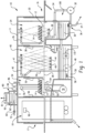
- Warewash machine 10 includes a housing 11 that can receive racks 12 of soiled wares 14 from an input side 16. The wares are moved through tunnel-like chambers from the input side toward a blower dryer unit 18 at an opposite exit end 17 of the warewash system by a suitable conveyor mechanism 20. Either continuously or intermittently moving conveyor mechanisms or combinations thereof may be used, depending, for example, on the style, model and size of the warewash system 10. Flight-type conveyors in which racks are not used are also possible.
- the racks 12 of soiled wares 14 enter the warewash system 10 through a flexible curtain 22 into a pre-wash chamber or zone 24 where sprays of liquid from upper and lower pre-wash manifolds 26 and 28 above and below the racks, respectively, function to flush heavier soil from the wares.
- the liquid for this purpose comes from a tank 30 and is delivered to the manifolds via a pump 32 and supply conduit 34.
- a drain structure 36 provides a single location where liquid is pumped from the tank 30 using the pump 32. Via the same drain structure, liquid can also be drained from the tank and out of the machine via drain path 37, for example, for a tank cleaning operation.
- the racks proceed to a next curtain 38 into a main wash chamber or zone 40, where the wares are subject to sprays of cleansing wash liquid (e.g., typically water with detergent) from upper and lower wash manifolds 42 and 44 with spray nozzles 47 and 49, respectively, these sprays being supplied through a supply conduit 46 by a pump 48, which draws from a main tank 50.
- a heater 58 such as an electrical immersion heater provided with suitable thermostatic controls (not shown), maintains the temperature of the cleansing liquid in the tank 50 at a suitable level.
- a device for adding a cleansing detergent to the liquid in tank 50 is During normal operation, pumps 32 and 48 are continuously driven, usually by separate motors, once the warewash system 10 is started for a period of time.
- the warewash system 10 may optionally include a power rinse (also known as post-wash) chamber or zone (not shown) that is substantially identical to main wash chamber 40.
- a power rinse also known as post-wash
- racks of wares proceed from the wash chamber 40 into the power rinse chamber, within which heated rinse water is sprayed onto the wares from upper and lower manifolds.
- the racks 12 of wares 14 exit the main wash chamber 40 through a curtain 52 into a final rinse chamber or zone 54.
- the final rinse chamber 54 is provided with upper and lower spray heads 56, 57 that are supplied with a flow of fresh hot water via pipe 62 running from a hot water booster 70 under the control of a solenoid valve 60 (or alternatively any other suitable valve capable of automatic control).
- a rack detector 64 may be actuated when a rack 12 of wares 14 is positioned in the final rinse chamber 54 and through suitable electrical controls (e.g., the controller mentioned below), the detector causes actuation of the solenoid valve 60 to open and admit the hot rinse water to the spray heads 56, 57.
- the water then drains from the wares and is directed into the tank 50 by gravity flow.
- the rinsed rack 12 of wares 14 then exits the final rinse chamber 54 through curtain 66, moving into dryer unit 18, before exiting the outlet end 17 of the machine.
- An exhaust system 80 for pulling hot moist air from the machine may be provided.
- a cold water input 72 line may run through a waste heat recovery unit 82 (e.g., a fin-and-tube heat exchanger through which the incoming water flows, though other variations are possible) to recover heat from the exhaust air flowing across and/or through the unit 82.
- the water line or flow path 72 then runs through one or more condensers 84 and 86 (e.g., in the form of plate heat exchangers or shell-and-tube heat exchangers, though other variations are possible), before delivering the water to the booster 70 for final heating.
- a condenser 88 may be located in the wash tank and a condenser 90 may be located in the blower dryer unit 18.
- a second waste heat recovery unit 92 may also be provided.
- the refrigerant medium circuit 100 includes a thermal expansion valve 101, which leads to a waste heat recovery unit 92 to recover heat from warm waste air (e.g., the exhaust air flow) after some heat has already been removed from the exhaust air flow by unit 82.
- a compressor 102 compresses the refrigerant to produce superheated refrigerant, which then flows sequentially through the condensers 86, 88, 90 and 84.
- condenser 86 delivers refrigerant heat to the incoming fresh water
- condenser 88 may take the form of coil submerged in the wash tank 50 to deliver refrigerant heat to the wash water
- condenser 90 may take the form of a coil over which the drying air blows to deliver some refrigerant heat to the drying air
- condenser 84 which may be a plate-type heat exchanger, delivers residual refrigerant heat to the incoming fresh water.
- this flow may be altered based upon warewash machine conditions.
- a temperature sensor 110 is provided to monitor the temperature of the wash tank condenser 88.
- the temperature sensor may be in direct contact with the condenser 88 or may simply monitor the surrounding wash tank liquid temperature, which in either case represents a temperature condition of the water in the tank and is therefore indicative of heat demand on the condenser 88. If the monitored temperature falls below a specified threshold temperature, a two way valve 112 is controlled to cause superheated refrigerant to bypass condenser 86 along bypass path 114 so as to flow directly to condenser 88, causing more heat to be transferred from the refrigerant to the wash tank wash liquid.
- valve 112 is configured to switch an entirety of the refrigerant medium flow between the path through condenser 86 and the bypass path.
- valve 112 could alternatively be a proportional valve that is capable of partially splitting the flow between the two paths in variable amounts (e.g., 80/20, 50/50, 20/80 or any desired split). This latter arrangement could provide for more precisely responding to heat demand on condenser 88.
- a controller 150 may be provided to effect switching of the valve 112 (or varied control of the valve) based upon temperature output of sensor 110, as well as for controlling other functions and operations of the machine.
- the term controller is intended to broadly encompass any circuit (e.g., solid state, application specific integrated circuit (ASIC), an electronic circuit, a combinational logic circuit, a field programmable gate array (FPGA)), processor (e.g., shared, dedicated, or group - including hardware or software that executes code) or other component, or a combination of some or all of the above, that carries out the control functions of the machine or the control functions of any component thereof.
- ASIC application specific integrated circuit
- FPGA field programmable gate array
- the system provides an advantageous method of refrigerant flow in a warewash machine that includes a chamber for receiving wares, where the chamber has at least one wash zone, and the refrigerant circuit includes a first condenser and a second condenser, the first condenser located upstream of the second condenser in the refrigerant circuit.
- the method involves: flowing refrigerant through both the first condenser and the second condenser; and selectively bypassing refrigerant flow around the first condenser based upon a monitored heat demand of the second condenser. Heat demand of the second condenser may be monitored by sensing a temperature condition of an environment of the second condenser.
- the monitoring may be continuous, periodic or triggered by some event (e.g., identification of a rack at a certain location in the machine).
- Refrigerant flow may be selectively bypassed around the first condenser in response to identification of a low temperature condition of the environment of the second condenser.
- the low temperature condition may be identified when a temperature sensor indicates a temperature below a set threshold temperature.
- the set threshold temperature can be varied (e.g., via an operator interface associated with the controller 150 or via a restricted service/maintenance personnel interface).
- refrigerant commonly refers to known acceptable refrigerants, but other thermal fluids could be used in refrigerant type circuits.
- refrigerant medium is intended to encompass all such traditional refrigerants and other thermal fluids.
- bypass of a first condenser in a four condenser system is primarily described, it is recognized that a lesser number of condensers could be used in some implementations and/or that one or more other or additional condensers could include a similar heat demand triggered bypass (e.g., selective bypass of condenser 88 based upon a heat demand of condenser 90). It is also recognized that bypass of an upstream condenser could be triggered by heat demand of any one of the downstream condensers (e.g., selective bypass of condenser 86 based upon heat demand of condenser 90). In addition, other refrigerant circuit conditions could be monitored in order to trigger selective bypass of a condenser.
Landscapes
- Engineering & Computer Science (AREA)
- Physics & Mathematics (AREA)
- Mechanical Engineering (AREA)
- Thermal Sciences (AREA)
- General Engineering & Computer Science (AREA)
- Water Supply & Treatment (AREA)
- Drying Of Solid Materials (AREA)
- Washing And Drying Of Tableware (AREA)
- Air Conditioning Control Device (AREA)
Claims (10)
- Geschirrspülmaschine (10) zum Waschen von Spülgut (14), aufweisend:- eine Kammer zur Aufnahme von Spülgut (14), wobei die Kammer zumindest eine Waschzone (40) aufweist;- einen Kältemittelkreislauf (100), der einen ersten Kondensator (86) und einen zweiten Kondensator (88) umfasst, wobei der erste Kondensator (86) stromaufwärts des zweiten Kondensators (88) in dem Kältemittelkreislauf (100) angeordnet ist, wobei der Kältemittelkreislauf (100) einen ersten Strömungsweg durch den ersten Kondensator (86) umfasst,dadurch gekennzeichnet, dassder Kältemittelkreislauf (100) einen zweiten Strömungsweg (114) in Umgehung des ersten Kondensators (86) und ein Ventil (112) zum selektiven Steuern, ob zumindest ein gewisses Kältemittel entlang des ersten Strömungswegs oder des zweiten Strömungswegs (114) strömt, umfasst,wobei das Ventil (112) basierend auf dem überwachten Wärmebedarf an dem zweiten Kondensator (88) selektiv gesteuert wird.
- Maschine (10) nach Anspruch 1,
wobei der erste Kondensator (86) so ausgelegt ist, dass er Kältemittelmittelwärme an Wasser abgibt, das an eine Zusatzheizung (70) der Maschine (10) zugeführt wird, und der zweite Kondensator (88) so ausgelegt ist, dass er Kältemittelmittelwärme an Waschflüssigkeit in einem Waschtank (50) der Maschine (10) abgibt. - Maschine (10) nach Anspruch 2,
wobei ein Temperatursensor (110) eine Temperatur einer Waschflüssigkeit innerhalb des Waschtanks (50) erfasst, um den Wärmebedarf an dem zweiten Kondensator (88) zu überwachen. - Maschine (10) nach Anspruch 3,
wobei eine Steuerung (150) mit dem Temperatursensor (110) verbunden ist und das Ventil (112) reaktiv steuert, um zumindest etwas Kältemittel entlang des zweiten Strömungswegs (114) zu strömen, wenn eine durch den Temperatursensor (110) angezeigte Temperatur unter einen festgelegten Schwellenwert fällt. - Maschine (10) nach einem der vorhergehenden Ansprüche,
wobei das Ventil (112) ein Proportionalventil (112) ist, das steuerbar ist, um eine gleichzeitige Strömung von gewissem Kältemittel entlang des ersten Strömungswegs und von gewissem Kältemittel entlang des zweiten Strömungswegs (114) zu erreichen. - Maschine (10) nach einem der vorhergehenden Ansprüche,
wobei eine Steuerung (150) konfiguriert ist, um das Auftreten eines vordefinierten Zustands des Kältemittelkreislaufs (100) stromabwärts des ersten Kondensators (86) zu identifizieren, und die Steuerung (150) so konfiguriert ist, dass die Steuerung (150) bei Identifikation des vordefinierten Zustands das Ventil (112) betätigt, um eine Strömung entlang des zweiten Strömungswegs (114) zu bewirken. - Maschine (10) nach Anspruch 6,
wobei der vordefinierte Zustand ein hoher Wärmebedarf des zweiten Kondensators (88) ist. - Verfahren zum Steuern eines Kältemittelstroms in einem Kältemittelkreislauf (100) einer Geschirrspülmaschine (10), die eine Kammer zum Aufnehmen von Spülgut (14) umfasst, wobei die Kammer zumindest eine Waschzone (40) aufweist, wobei der Kältemittelkreislauf (100) einen ersten Kondensator (86) und einen zweiten Kondensator (88) umfasst, wobei der erste Kondensator (86) stromaufwärts des zweiten Kondensators (88) in dem Kältemittelkreislauf (100) angeordnet ist, wobei das Verfahren aufweist:- Strömen von Kältemittel durch sowohl den ersten Kondensator (86) als auch den zweiten Kondensator (88);
gekennzeichnet durch- selektives Umgehen von zumindest einem Teil des Kältemittelstroms um den ersten Kondensator (86) basierend auf der Identifizierung eines vordefinierten Zustands des Kältemittelkreislaufs (100) stromabwärts des ersten Kondensators (86),wobei der vordefinierte Zustand des Kältemittelkreislaufs (100) ein Wärmebedarfszustand des zweiten Kondensators (88) ist. - Verfahren nach Anspruch 8,
wobei der Wärmebedarf des zweiten Kondensators (88) durch Erfassen eines Temperaturzustands einer Umgebung des zweiten Kondensators (88) überwacht wird. - Verfahren nach Anspruch 9,
wobei zumindest ein gewisser Kältemittelstrom selektiv um den ersten Kondensator (86) als Reaktion auf die Identifizierung eines Niedrigtemperaturzustands der Umgebung des zweiten Kondensators (88) herumgeführt wird.
Applications Claiming Priority (3)
| Application Number | Priority Date | Filing Date | Title |
|---|---|---|---|
| US201562199519P | 2015-07-31 | 2015-07-31 | |
| US15/177,965 US10178937B2 (en) | 2015-07-31 | 2016-06-09 | Warewasher with heat recovery system |
| PCT/US2016/043069 WO2017023547A1 (en) | 2015-07-31 | 2016-07-20 | Warewasher with heat recovery system |
Publications (2)
| Publication Number | Publication Date |
|---|---|
| EP3328262A1 EP3328262A1 (de) | 2018-06-06 |
| EP3328262B1 true EP3328262B1 (de) | 2024-09-04 |
Family
ID=57886223
Family Applications (1)
| Application Number | Title | Priority Date | Filing Date |
|---|---|---|---|
| EP16748199.3A Active EP3328262B1 (de) | 2015-07-31 | 2016-07-20 | Geschirrspülmaschine mit wärmerückgewinnungssystem |
Country Status (4)
| Country | Link |
|---|---|
| US (2) | US10178937B2 (de) |
| EP (1) | EP3328262B1 (de) |
| CN (1) | CN108024687B (de) |
| WO (1) | WO2017023547A1 (de) |
Families Citing this family (5)
| Publication number | Priority date | Publication date | Assignee | Title |
|---|---|---|---|---|
| US10178937B2 (en) * | 2015-07-31 | 2019-01-15 | Illinois Tool Works Inc. | Warewasher with heat recovery system |
| US10178940B2 (en) * | 2015-07-31 | 2019-01-15 | Illinois Tool Works Inc. | Warewasher with heat recovery system |
| KR101778172B1 (ko) * | 2016-11-15 | 2017-09-26 | 주식회사프라임 | 식기 세척기 |
| CN109662674A (zh) * | 2018-12-14 | 2019-04-23 | 佛山市顺德区美的洗涤电器制造有限公司 | 用于洗碗机的干燥装置及具有其的洗碗机 |
| DE102023100906A1 (de) * | 2023-01-16 | 2024-07-18 | Illinois Tool Works Inc. | Spülmaschine mit wärmerückgewinnungsvorrichtung |
Family Cites Families (66)
| Publication number | Priority date | Publication date | Assignee | Title |
|---|---|---|---|---|
| US3315293A (en) | 1965-02-26 | 1967-04-25 | Everett E Werneke | Utensil prewashing machine |
| US3598131A (en) | 1969-08-12 | 1971-08-10 | Adamation Inc | Steam collection system for dishwashing machines |
| US3789860A (en) | 1971-11-05 | 1974-02-05 | Hobart Mfg Co | Method and apparatus for treating dishwasher discharge |
| FR2259576A1 (en) | 1972-08-16 | 1975-08-29 | Baker Larry | Low water consumption washing apparatus such as shower - includes water source, pressurized gas source and device for carrying water droplets on gas flow to generate high pressure cleaning water jet |
| SE382496B (sv) | 1973-10-09 | 1976-02-02 | R Christensen | Sett och anleggning for vermeatervinning. |
| DE2457182C2 (de) | 1974-12-03 | 1983-09-15 | Stierlen-Maquet Ag, 7550 Rastatt | Wärmerückgewinnungseinrichtung für eine Geschirrspülmaschine |
| US4125148A (en) | 1976-01-07 | 1978-11-14 | Stainless Equipment Company | Method for utilization of waste energy |
| US4098616A (en) | 1977-03-07 | 1978-07-04 | Elsters, Inc. | Recirculating dishwasher hood |
| US4529032A (en) | 1978-06-30 | 1985-07-16 | Molitor Industries, Inc. | Method of and apparatus for recovery of waste energy |
| US4219044A (en) | 1978-10-13 | 1980-08-26 | Wilson Warren M | Control valve assembly |
| SE8006392L (sv) | 1980-09-12 | 1982-03-13 | Jacob Weitman | Sett och system for vermeatervinning |
| US4531572A (en) | 1980-09-29 | 1985-07-30 | Molitor Victor D | Method of and unit for recovery of waste energy |
| US4326551A (en) | 1980-10-27 | 1982-04-27 | Hobart Corporation | Heat recovery system for a dishwasher |
| JPH05285085A (ja) | 1992-04-08 | 1993-11-02 | Toshiba Corp | 食器洗浄機 |
| DE9410453U1 (de) | 1994-06-28 | 1994-12-01 | Premark Feg Corp | Ablaufwasser-Wärmerückgewinnungsanlage und Spülmaschine |
| US5511570B1 (en) | 1994-10-13 | 1997-08-26 | Stero Co | Warewasher employing infrared burner |
| IT238849Y1 (it) | 1995-05-26 | 2000-11-15 | Zanussi Elettrodomestici | Lavastoviglie con mezzi elettrici di riscaldamento |
| IT1289370B1 (it) | 1996-04-10 | 1998-10-02 | Electrolux Zanussi Elettrodome | Macchina lavatrice con serbatoio d'acqua multifunzionale |
| DE19707287C2 (de) * | 1997-02-24 | 2000-06-08 | Premark Feg L L C N D Ges D St | Wärmepumpe für eine Geschirrspülvorrichtung |
| US5884694A (en) | 1997-03-26 | 1999-03-23 | Tanenbaum; Aaron | Bathroom dehumidifier method and apparatus |
| JP3985365B2 (ja) | 1997-12-25 | 2007-10-03 | 株式会社デンソー | 車両用空調装置 |
| US5934078A (en) | 1998-02-03 | 1999-08-10 | Astronautics Corporation Of America | Reciprocating active magnetic regenerator refrigeration apparatus |
| EP1014015A4 (de) * | 1998-06-11 | 2001-03-14 | Sanyo Electric Co | Kältemittelsammelvorrichtung,kältemittelsammelverfahren,kühlschrank mit kältemittelsammelvorrichtung,regelverfahren für kältemittel in kältemittelkreislauf oder rückgewinnungsvorrichtung und rückgewinningsverfahren für kältemittelsammelvorrichtung |
| US6170166B1 (en) | 1998-07-10 | 2001-01-09 | Ecolab Inc. | Removal of heat and water vapor from commercial dishwashing machines |
| US6895788B2 (en) | 1999-08-30 | 2005-05-24 | Mcsm, Llc | Appliance safety valve assembly |
| US6591846B1 (en) | 2000-11-15 | 2003-07-15 | Jackson Msc, Inc. | Wrap around booster |
| US7103992B2 (en) | 2001-01-31 | 2006-09-12 | Winterhalter Gastronm Gmbh | Industrial dishwasher |
| US6357245B1 (en) | 2001-05-01 | 2002-03-19 | Cohand Technology Co., Ltd. | Apparatus for making hot-water by air conditioner/heater |
| JP3742356B2 (ja) | 2002-03-20 | 2006-02-01 | 株式会社日立製作所 | ヒートポンプ給湯機 |
| US7017592B2 (en) | 2002-12-10 | 2006-03-28 | Pro-Environmental Inc. | Regenerative fume-incinerator with on-line burn-out and wash-down system |
| US6857578B2 (en) | 2003-05-15 | 2005-02-22 | Lennox Manufacturing Inc. | Combination water heating and space heating apparatus and control therefor |
| US20040261820A1 (en) | 2003-06-30 | 2004-12-30 | Monsrud Lee J. | Dishwashing machine having a water vapor recovery line and method for washing articles |
| KR100765674B1 (ko) | 2003-12-10 | 2007-10-12 | 마츠시타 덴끼 산교 가부시키가이샤 | 열교환기 및 그것을 구비한 세정 장치 |
| ITTO20040232A1 (it) | 2004-04-14 | 2004-07-14 | Eltek Spa | Dispositivo per prevenire il deterioramento di sostanze in esso contenute e il comportamento anomalo di sue parti interne |
| DE102004046758A1 (de) | 2004-09-24 | 2006-04-06 | Meiko Maschinenbau Gmbh & Co. Kg | Verfahren und Anordnung zum energiesparenden Betrieb von Spülmaschinen |
| US7744007B2 (en) | 2004-11-01 | 2010-06-29 | Honeywell International Inc. | Thermostatic mixing valves and systems |
| WO2006097294A1 (de) | 2005-03-16 | 2006-09-21 | Meiko Maschinenbau Gmbh & Co. Kg | Verfahren zur beurteilung und sicherstellung der thermischen hygienewirkung in einer mehrtankgeschirrspülmaschine |
| CN2798838Y (zh) * | 2005-04-26 | 2006-07-26 | 袁婉笑 | 一种节水节能商用洗碟装置 |
| US7849530B2 (en) | 2005-10-25 | 2010-12-14 | Craig Hendricks | Waste-water heat recovery system |
| DE102005062942A1 (de) * | 2005-12-29 | 2007-07-05 | BSH Bosch und Siemens Hausgeräte GmbH | Hausgerät umfassend einen Adsorptionsapparat, und Verfahren zum Betrieb eines solchen Hausgerätes |
| US20070170270A1 (en) | 2006-01-24 | 2007-07-26 | Spx Corporation | Waste water heat recovery system and method |
| US20080000616A1 (en) | 2006-06-21 | 2008-01-03 | Nobile John R | Heat exchanger and use thereof in showers |
| DE102006039434A1 (de) | 2006-08-23 | 2008-05-29 | Meiko Maschinenbau Gmbh & Co. Kg | Verfahren zur Beurteilung und Sicherstellung der thermischen Hygienewirkung in einer Mehrtankgeschirrspülmaschine |
| US20080087307A1 (en) | 2006-10-17 | 2008-04-17 | Jung Youp Han | Dishwasher |
| JP2008267616A (ja) * | 2007-04-16 | 2008-11-06 | Hanshin Electric Co Ltd | 家庭内熱エネルギ効率利用システム |
| JP2008279026A (ja) * | 2007-05-10 | 2008-11-20 | Hanshin Electric Co Ltd | 食器洗い乾燥機 |
| DE102007053381B3 (de) | 2007-11-09 | 2009-04-02 | Meiko Maschinenbau Gmbh & Co.Kg | Geschirrspülmaschine mit Latentwärmespeicher |
| US8157924B2 (en) | 2008-04-09 | 2012-04-17 | Premark Feg L.L.C. | Warewasher including heat recovery system with hot water supplement |
| US7946300B2 (en) | 2008-05-06 | 2011-05-24 | Jong-Deuk Kim | Rinse water heating device for dish washer |
| US8146612B2 (en) | 2008-08-04 | 2012-04-03 | Premark Feg L.L.C. | Warewasher with water energy recovery system |
| US8498523B2 (en) | 2009-02-03 | 2013-07-30 | Intellihot, Inc. | Apparatus and control method for a hybrid tankless water heater |
| US8679261B2 (en) | 2009-04-15 | 2014-03-25 | Premark Feg L.L.C. | Box-type warewasher including heat recovery system for reducing air moisture level at the end of cycle |
| SG166696A1 (en) * | 2009-05-15 | 2010-12-29 | K One Ind Pte Ltd | An industrial dishwasher |
| US8770154B2 (en) | 2009-09-03 | 2014-07-08 | Champion Industries, Inc. | Heat exchanger water heating system for commercial dishwasher |
| EP2449945B1 (de) * | 2012-01-30 | 2020-07-29 | V-Zug AG | Haushaltgerät mit Wärmepumpe am Prozesswasserkreislauf |
| DE102012013322A1 (de) * | 2012-07-06 | 2014-01-09 | Eichenauer Heizelemente Gmbh & Co. Kg | Geschirrspülmaschine |
| EP2746454A1 (de) | 2012-12-18 | 2014-06-25 | Electrolux Home Products Corporation N.V. | Wasch- und Trocknungsmaschine |
| CN203914825U (zh) * | 2013-06-08 | 2014-11-05 | 林波荣 | 用于食堂或餐厅洗碗机的余热利用系统 |
| CN203408012U (zh) * | 2013-07-11 | 2014-01-29 | 东莞市微电环保科技有限公司 | 一种洗碗机的加热系统 |
| CN103519764B (zh) * | 2013-10-21 | 2016-06-08 | 扬州工业职业技术学院 | 超声波洗碗机余热回收的综合节能装置 |
| DE102013224440A1 (de) | 2013-11-28 | 2015-05-28 | Illinois Tool Works Inc. | Transportspülmaschine, insbesondere gewerbliche Transportspülmaschine |
| KR101586368B1 (ko) * | 2013-12-26 | 2016-01-18 | 동부대우전자 주식회사 | 흡수식 냉동 시스템 |
| CN204218845U (zh) * | 2014-10-13 | 2015-03-25 | 刘晓明 | 餐具清洗机 |
| CN204313358U (zh) * | 2014-11-07 | 2015-05-06 | 青岛万力科技有限公司 | 一种分区采暖换热系统 |
| US10178940B2 (en) * | 2015-07-31 | 2019-01-15 | Illinois Tool Works Inc. | Warewasher with heat recovery system |
| US10178937B2 (en) * | 2015-07-31 | 2019-01-15 | Illinois Tool Works Inc. | Warewasher with heat recovery system |
-
2016
- 2016-06-09 US US15/177,965 patent/US10178937B2/en active Active
- 2016-07-20 CN CN201680044194.2A patent/CN108024687B/zh active Active
- 2016-07-20 WO PCT/US2016/043069 patent/WO2017023547A1/en not_active Ceased
- 2016-07-20 EP EP16748199.3A patent/EP3328262B1/de active Active
-
2019
- 2019-01-03 US US16/238,650 patent/US10722097B2/en active Active
Also Published As
| Publication number | Publication date |
|---|---|
| US10722097B2 (en) | 2020-07-28 |
| US10178937B2 (en) | 2019-01-15 |
| WO2017023547A1 (en) | 2017-02-09 |
| US20190133405A1 (en) | 2019-05-09 |
| EP3328262A1 (de) | 2018-06-06 |
| US20170027407A1 (en) | 2017-02-02 |
| CN108024687A (zh) | 2018-05-11 |
| CN108024687B (zh) | 2021-06-04 |
Similar Documents
| Publication | Publication Date | Title |
|---|---|---|
| US10722097B2 (en) | Warewasher with heat recovery system | |
| EP3328259B1 (de) | Geschirrspülmaschine mit wärmerückgewinnungssystem | |
| US10722099B2 (en) | Warewasher with heat recovery system | |
| US8663395B2 (en) | Warewasher including heat recovery system with hot water supplement | |
| EP3328258B1 (de) | Geschirrspülmaschine mit wärmerückgewinnungssystem | |
| CN108697296B (zh) | 器皿清洗机器干燥系统和方法 | |
| US11751747B2 (en) | Warewash machine energy conservation incorporating vent controls | |
| US10342406B2 (en) | Warewasher idling system and method |
Legal Events
| Date | Code | Title | Description |
|---|---|---|---|
| STAA | Information on the status of an ep patent application or granted ep patent |
Free format text: STATUS: THE INTERNATIONAL PUBLICATION HAS BEEN MADE |
|
| PUAI | Public reference made under article 153(3) epc to a published international application that has entered the european phase |
Free format text: ORIGINAL CODE: 0009012 |
|
| STAA | Information on the status of an ep patent application or granted ep patent |
Free format text: STATUS: REQUEST FOR EXAMINATION WAS MADE |
|
| 17P | Request for examination filed |
Effective date: 20180125 |
|
| AK | Designated contracting states |
Kind code of ref document: A1 Designated state(s): AL AT BE BG CH CY CZ DE DK EE ES FI FR GB GR HR HU IE IS IT LI LT LU LV MC MK MT NL NO PL PT RO RS SE SI SK SM TR |
|
| AX | Request for extension of the european patent |
Extension state: BA ME |
|
| DAV | Request for validation of the european patent (deleted) | ||
| DAX | Request for extension of the european patent (deleted) | ||
| STAA | Information on the status of an ep patent application or granted ep patent |
Free format text: STATUS: EXAMINATION IS IN PROGRESS |
|
| 17Q | First examination report despatched |
Effective date: 20200821 |
|
| GRAP | Despatch of communication of intention to grant a patent |
Free format text: ORIGINAL CODE: EPIDOSNIGR1 |
|
| STAA | Information on the status of an ep patent application or granted ep patent |
Free format text: STATUS: GRANT OF PATENT IS INTENDED |
|
| INTG | Intention to grant announced |
Effective date: 20240624 |
|
| GRAS | Grant fee paid |
Free format text: ORIGINAL CODE: EPIDOSNIGR3 |
|
| GRAA | (expected) grant |
Free format text: ORIGINAL CODE: 0009210 |
|
| STAA | Information on the status of an ep patent application or granted ep patent |
Free format text: STATUS: THE PATENT HAS BEEN GRANTED |
|
| P01 | Opt-out of the competence of the unified patent court (upc) registered |
Free format text: CASE NUMBER: APP_41365/2024 Effective date: 20240712 |
|
| AK | Designated contracting states |
Kind code of ref document: B1 Designated state(s): AL AT BE BG CH CY CZ DE DK EE ES FI FR GB GR HR HU IE IS IT LI LT LU LV MC MK MT NL NO PL PT RO RS SE SI SK SM TR |
|
| REG | Reference to a national code |
Ref country code: GB Ref legal event code: FG4D |
|
| REG | Reference to a national code |
Ref country code: CH Ref legal event code: EP |
|
| REG | Reference to a national code |
Ref country code: IE Ref legal event code: FG4D |
|
| REG | Reference to a national code |
Ref country code: DE Ref legal event code: R096 Ref document number: 602016089236 Country of ref document: DE |
|
| REG | Reference to a national code |
Ref country code: LT Ref legal event code: MG9D |
|
| REG | Reference to a national code |
Ref country code: NL Ref legal event code: MP Effective date: 20240904 |
|
| PG25 | Lapsed in a contracting state [announced via postgrant information from national office to epo] |
Ref country code: NO Free format text: LAPSE BECAUSE OF FAILURE TO SUBMIT A TRANSLATION OF THE DESCRIPTION OR TO PAY THE FEE WITHIN THE PRESCRIBED TIME-LIMIT Effective date: 20241204 |
|
| PG25 | Lapsed in a contracting state [announced via postgrant information from national office to epo] |
Ref country code: PL Free format text: LAPSE BECAUSE OF FAILURE TO SUBMIT A TRANSLATION OF THE DESCRIPTION OR TO PAY THE FEE WITHIN THE PRESCRIBED TIME-LIMIT Effective date: 20240904 Ref country code: GR Free format text: LAPSE BECAUSE OF FAILURE TO SUBMIT A TRANSLATION OF THE DESCRIPTION OR TO PAY THE FEE WITHIN THE PRESCRIBED TIME-LIMIT Effective date: 20241205 Ref country code: FI Free format text: LAPSE BECAUSE OF FAILURE TO SUBMIT A TRANSLATION OF THE DESCRIPTION OR TO PAY THE FEE WITHIN THE PRESCRIBED TIME-LIMIT Effective date: 20240904 |
|
| PG25 | Lapsed in a contracting state [announced via postgrant information from national office to epo] |
Ref country code: BG Free format text: LAPSE BECAUSE OF FAILURE TO SUBMIT A TRANSLATION OF THE DESCRIPTION OR TO PAY THE FEE WITHIN THE PRESCRIBED TIME-LIMIT Effective date: 20240904 |
|
| PG25 | Lapsed in a contracting state [announced via postgrant information from national office to epo] |
Ref country code: LV Free format text: LAPSE BECAUSE OF FAILURE TO SUBMIT A TRANSLATION OF THE DESCRIPTION OR TO PAY THE FEE WITHIN THE PRESCRIBED TIME-LIMIT Effective date: 20240904 |
|
| PG25 | Lapsed in a contracting state [announced via postgrant information from national office to epo] |
Ref country code: HR Free format text: LAPSE BECAUSE OF FAILURE TO SUBMIT A TRANSLATION OF THE DESCRIPTION OR TO PAY THE FEE WITHIN THE PRESCRIBED TIME-LIMIT Effective date: 20240904 |
|
| PG25 | Lapsed in a contracting state [announced via postgrant information from national office to epo] |
Ref country code: RS Free format text: LAPSE BECAUSE OF FAILURE TO SUBMIT A TRANSLATION OF THE DESCRIPTION OR TO PAY THE FEE WITHIN THE PRESCRIBED TIME-LIMIT Effective date: 20241204 Ref country code: ES Free format text: LAPSE BECAUSE OF FAILURE TO SUBMIT A TRANSLATION OF THE DESCRIPTION OR TO PAY THE FEE WITHIN THE PRESCRIBED TIME-LIMIT Effective date: 20240904 |
|
| PG25 | Lapsed in a contracting state [announced via postgrant information from national office to epo] |
Ref country code: RS Free format text: LAPSE BECAUSE OF FAILURE TO SUBMIT A TRANSLATION OF THE DESCRIPTION OR TO PAY THE FEE WITHIN THE PRESCRIBED TIME-LIMIT Effective date: 20241204 Ref country code: PL Free format text: LAPSE BECAUSE OF FAILURE TO SUBMIT A TRANSLATION OF THE DESCRIPTION OR TO PAY THE FEE WITHIN THE PRESCRIBED TIME-LIMIT Effective date: 20240904 Ref country code: NO Free format text: LAPSE BECAUSE OF FAILURE TO SUBMIT A TRANSLATION OF THE DESCRIPTION OR TO PAY THE FEE WITHIN THE PRESCRIBED TIME-LIMIT Effective date: 20241204 Ref country code: LV Free format text: LAPSE BECAUSE OF FAILURE TO SUBMIT A TRANSLATION OF THE DESCRIPTION OR TO PAY THE FEE WITHIN THE PRESCRIBED TIME-LIMIT Effective date: 20240904 Ref country code: HR Free format text: LAPSE BECAUSE OF FAILURE TO SUBMIT A TRANSLATION OF THE DESCRIPTION OR TO PAY THE FEE WITHIN THE PRESCRIBED TIME-LIMIT Effective date: 20240904 Ref country code: GR Free format text: LAPSE BECAUSE OF FAILURE TO SUBMIT A TRANSLATION OF THE DESCRIPTION OR TO PAY THE FEE WITHIN THE PRESCRIBED TIME-LIMIT Effective date: 20241205 Ref country code: FI Free format text: LAPSE BECAUSE OF FAILURE TO SUBMIT A TRANSLATION OF THE DESCRIPTION OR TO PAY THE FEE WITHIN THE PRESCRIBED TIME-LIMIT Effective date: 20240904 Ref country code: ES Free format text: LAPSE BECAUSE OF FAILURE TO SUBMIT A TRANSLATION OF THE DESCRIPTION OR TO PAY THE FEE WITHIN THE PRESCRIBED TIME-LIMIT Effective date: 20240904 Ref country code: BG Free format text: LAPSE BECAUSE OF FAILURE TO SUBMIT A TRANSLATION OF THE DESCRIPTION OR TO PAY THE FEE WITHIN THE PRESCRIBED TIME-LIMIT Effective date: 20240904 |
|
| REG | Reference to a national code |
Ref country code: AT Ref legal event code: MK05 Ref document number: 1719488 Country of ref document: AT Kind code of ref document: T Effective date: 20240904 |
|
| PG25 | Lapsed in a contracting state [announced via postgrant information from national office to epo] |
Ref country code: NL Free format text: LAPSE BECAUSE OF FAILURE TO SUBMIT A TRANSLATION OF THE DESCRIPTION OR TO PAY THE FEE WITHIN THE PRESCRIBED TIME-LIMIT Effective date: 20240904 |
|
| PG25 | Lapsed in a contracting state [announced via postgrant information from national office to epo] |
Ref country code: IS Free format text: LAPSE BECAUSE OF FAILURE TO SUBMIT A TRANSLATION OF THE DESCRIPTION OR TO PAY THE FEE WITHIN THE PRESCRIBED TIME-LIMIT Effective date: 20250104 Ref country code: PT Free format text: LAPSE BECAUSE OF FAILURE TO SUBMIT A TRANSLATION OF THE DESCRIPTION OR TO PAY THE FEE WITHIN THE PRESCRIBED TIME-LIMIT Effective date: 20250106 |
|
| PG25 | Lapsed in a contracting state [announced via postgrant information from national office to epo] |
Ref country code: RO Free format text: LAPSE BECAUSE OF FAILURE TO SUBMIT A TRANSLATION OF THE DESCRIPTION OR TO PAY THE FEE WITHIN THE PRESCRIBED TIME-LIMIT Effective date: 20240904 Ref country code: SM Free format text: LAPSE BECAUSE OF FAILURE TO SUBMIT A TRANSLATION OF THE DESCRIPTION OR TO PAY THE FEE WITHIN THE PRESCRIBED TIME-LIMIT Effective date: 20240904 |
|
| PG25 | Lapsed in a contracting state [announced via postgrant information from national office to epo] |
Ref country code: EE Free format text: LAPSE BECAUSE OF FAILURE TO SUBMIT A TRANSLATION OF THE DESCRIPTION OR TO PAY THE FEE WITHIN THE PRESCRIBED TIME-LIMIT Effective date: 20240904 Ref country code: AT Free format text: LAPSE BECAUSE OF FAILURE TO SUBMIT A TRANSLATION OF THE DESCRIPTION OR TO PAY THE FEE WITHIN THE PRESCRIBED TIME-LIMIT Effective date: 20240904 |
|
| PG25 | Lapsed in a contracting state [announced via postgrant information from national office to epo] |
Ref country code: CZ Free format text: LAPSE BECAUSE OF FAILURE TO SUBMIT A TRANSLATION OF THE DESCRIPTION OR TO PAY THE FEE WITHIN THE PRESCRIBED TIME-LIMIT Effective date: 20240904 |
|
| PG25 | Lapsed in a contracting state [announced via postgrant information from national office to epo] |
Ref country code: IT Free format text: LAPSE BECAUSE OF FAILURE TO SUBMIT A TRANSLATION OF THE DESCRIPTION OR TO PAY THE FEE WITHIN THE PRESCRIBED TIME-LIMIT Effective date: 20240904 Ref country code: SK Free format text: LAPSE BECAUSE OF FAILURE TO SUBMIT A TRANSLATION OF THE DESCRIPTION OR TO PAY THE FEE WITHIN THE PRESCRIBED TIME-LIMIT Effective date: 20240904 |
|
| REG | Reference to a national code |
Ref country code: DE Ref legal event code: R097 Ref document number: 602016089236 Country of ref document: DE |
|
| PG25 | Lapsed in a contracting state [announced via postgrant information from national office to epo] |
Ref country code: DK Free format text: LAPSE BECAUSE OF FAILURE TO SUBMIT A TRANSLATION OF THE DESCRIPTION OR TO PAY THE FEE WITHIN THE PRESCRIBED TIME-LIMIT Effective date: 20240904 |
|
| PLBE | No opposition filed within time limit |
Free format text: ORIGINAL CODE: 0009261 |
|
| STAA | Information on the status of an ep patent application or granted ep patent |
Free format text: STATUS: NO OPPOSITION FILED WITHIN TIME LIMIT |
|
| 26N | No opposition filed |
Effective date: 20250605 |
|
| PG25 | Lapsed in a contracting state [announced via postgrant information from national office to epo] |
Ref country code: SE Free format text: LAPSE BECAUSE OF FAILURE TO SUBMIT A TRANSLATION OF THE DESCRIPTION OR TO PAY THE FEE WITHIN THE PRESCRIBED TIME-LIMIT Effective date: 20240904 |
|
| REG | Reference to a national code |
Ref country code: CH Ref legal event code: H13 Free format text: ST27 STATUS EVENT CODE: U-0-0-H10-H13 (AS PROVIDED BY THE NATIONAL OFFICE) Effective date: 20260224 |
|
| PG25 | Lapsed in a contracting state [announced via postgrant information from national office to epo] |
Ref country code: LU Free format text: LAPSE BECAUSE OF NON-PAYMENT OF DUE FEES Effective date: 20250720 |